1
Chapter 4
Cabling the RF Switch With the Cisco uBR10012 CMTS Cable Interface Line Cards
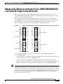
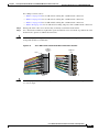
Connecting the RF Cables (MC16x, MC28C Line Cards)
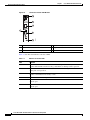
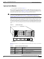
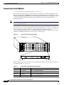
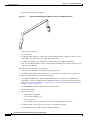
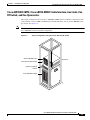
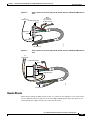
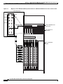
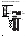
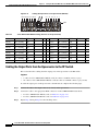
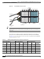
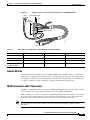
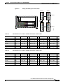
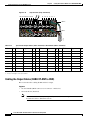
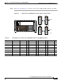
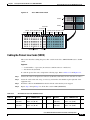
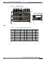
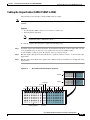
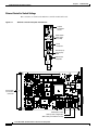
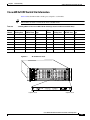
Figure 4-12
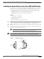
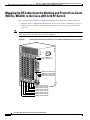
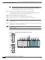
Cabling the Input Ports on the Upconverter (MC28C)
16 15 14 13 12 11 10 9
8 7 6 5 4 3 2 1
103293
Input
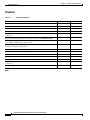
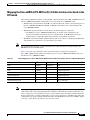
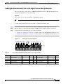
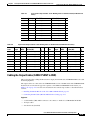
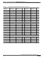
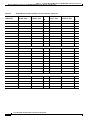
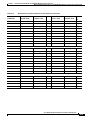
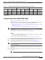
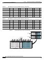
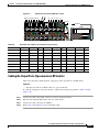
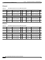
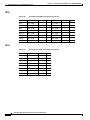
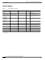
Table 4-4
Cisco uBR10-LCP2-MC28C Cabling (DS Ports to the Upconverter)
Color
Line Card Slot
DS Port
UPx Conn
Brown
8/0—working
DS1
Gray
8/0—working
Brown
D
Color
Line Card Slot
DS Port
UPx Conn
16
Brown
6/0—working
DS1
8
DS0
15
Gray
6/0—working
DS0
7
8/1—working
DS1
14
Brown
6/1—working
DS1
6
Gray
8/1—working
DS0
13
Gray
6/1—working
DS0
5
Brown
7/0—working
DS1
12
Brown
5/0—working
DS1
4
Gray
7/0—working
DS0
11
Gray
5/0—working
DS0
3
Brown
7/1—working
DS1
10
Brown
5/1—protect
DS1
2
Gray
7/1—working
DS0
9
Gray
5/1—protect
DS0
1
D
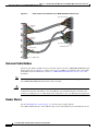
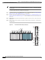
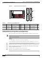
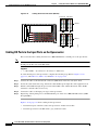
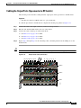
Cabling the Output Ports from the Upconverter to the RF Switch
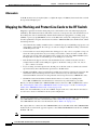
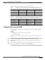
This section describes cabling from the output ports on the upconverter to the RF switch.
Equipment
•
8 cables for Cisco uBR10-LCP2-MC16x cards (F-connector to MCX connector–gray)
•
16 cables for Cisco uBR10-LCP2-MC28C cards (F-connector to MCX connector–gray, brown)
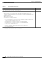
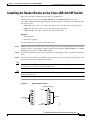
To cable the output ports on the upconverter to the RF switch, complete the following steps.
Step 1
Connect the cable to the output connector (1–lower) on the upconverter.
Step 2
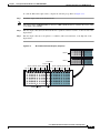
Connect the cable to the appropriate MCX connection on the CABLE PLANT header block.
Step 3
•
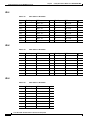
For Cisco uBR10-LCP2-MC16x cards, see Table 4-5 on page 4-19.
•
For Cisco uBR10-LCP2-MC28C cards, see Table 4-6 on page 4-19.
Repeat Step 1 through Step 2 for the remaining cables
Cisco uBR-3x10 RF Switch Hardware Installation and Cabling Guide
4-18
OL-1984-06