1
Figures
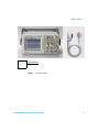
Figure 1. Package Contents 19
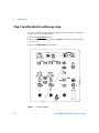
Figure 2. Save/Recall Button 22
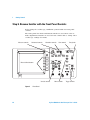
Figure 3. Front Panel 24
Figure 4. Menu Buttons 26
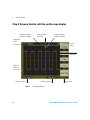
Figure 5. Oscilloscope Display 28
Figure 6. Auto-Scale Button 29
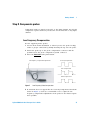
Figure 7. Low Frequency Probe Compensation 31
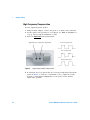
Figure 8. High Frequency Probe Compensation 32
Figure 9. Run Control Buttons 33
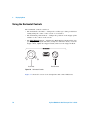
Figure 10. Horizontal Controls 36
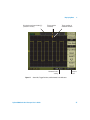
Figure 11. Status Bar, Trigger Position, and Horizontal Scale Indicators
Figure 12. Delayed Sweep Time Base Window 40
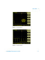
Figure 13. X-Y Display Format Showing In-Phase Waveforms 41
Figure 14. Trigger Holdoff 42
Figure 15. Vertical Controls 44
Figure 16. DC Coupling Control 47
Figure 17. AC Coupling Control 47
Figure 18. GND Coupling Control 48
Figure 19. BW Limit Control ON 49
Figure 20. BW Limit Control OFF 49
Figure 21. Probe Attenuation Set to 1000:1 50
Figure 22. Waveform Before Inversion 52
Figure 23. Waveform After Inversion 52
Figure 24. Math Scale Setting Value 53
Figure 25. FFT Waveform 56
Figure 26. Display Button 58
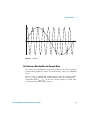
Figure 27. Alaising 63
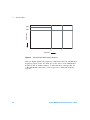
Figure 28. Theoretical Brick-Wall Frequency Response 64
Agilent 3000 Series Oscilloscopes User’s Guide
37
13