1
PLC Interface Port
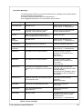
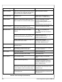
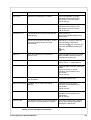
Pin Assignment of the PLC Interface
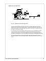
For use in a network the Printer-Applicator-System is equipped with a PLC interface to start
and interrupt the printing and labelling process. It also passes on state information as well as
error messages of the Printer-Applicator-System to the control of the network.
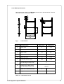
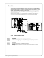
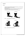
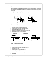
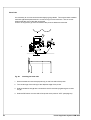
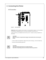
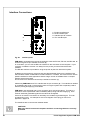
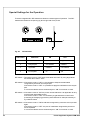
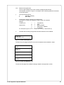
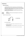
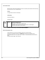
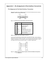
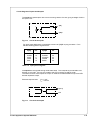
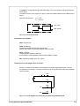
The interface has a 25 pin SUB-D connector (1).
PIN 1
PIN 13
1
PIN 14
PIN 25
Fig. C-7 Connector of the PLC-interface (side of the printer)
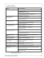
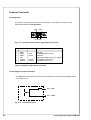
Pin
Signal
1
2
3
4
5
6
7
8
9
10
11
12
13
14
15
16
17
18
19
20
21
22
23
24
25
n.c.
n.c.
XDKO
XDNB
XEPOS
XESP
RUEL
XEDG
EXF
EUEB
STRT
DRW
ESP
n.c.
XTIV
XVW
XEDST
XRTA
n.c.
n.c.
EXFR
EUEBR
STARTR
DRWR
ESPR
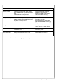
Direction
Function
variation without applicator variation with applicator
output
output
output
output
(output)
output
input
input
input
input
input
Printhead position
Printer not ready
Label is printed
Label is dispensed
revers line (for all outputs)
No existing print job
External error
Label is taken
Start signal
Print repeat
Label dispense
Printhead position
Printer, applicator not ready
Pad in labelling position
Applying process is ready
Revers line (for all outputs)
No existing print job
External error
Recycle part in position
Start signal
GoodRead (Scan result)
90°-labelling
output
output
output
output
Position of the peel-off table
Warning end of material
Print of label has started
without function
Position of the peel-off table
Warning end of material
Pad in starting position
Activate the recycle part
(input)
(input)
(input)
(input)
(input)
External error (revers line)
Label is taken (revers line)
Start signal (revers line)
Print repeat (revers line)
Label dispense (revers line)
External error (revers line)
Recycle part pos. (revers line)
Start signal (revers line)
Not connect
90°-labelling (revers line)
Table C-3 Pin assignment of the PLC interface
C-4
Printer-Applicator-System PAM 3000