1
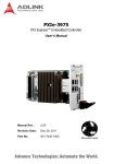
GIE64+ 4-CH PoE GigE Vision Interface Card User’s Manual Manual Rev.: 2.00 Revision Date: Feb. 24, 2012 Part No: 50-11245-1000 Advance Technologies; Automate the World. Revision History ii Revision Release Date 2.00 Feb. 24, 2012 Description of Change(s) Initial release GIE64+ Preface Copyright 2012 ADLINK Technology Inc. This document contains proprietary information protected by copyright. All rights are reserved. No part of this manual may be reproduced by any mechanical, electronic, or other means in any form without prior written permission of the manufacturer. Disclaimer The information in this document is subject to change without prior notice in order to improve reliability, design, and function and does not represent a commitment on the part of the manufacturer. In no event will the manufacturer be liable for direct, indirect, special, incidental, or consequential damages arising out of the use or inability to use the product or documentation, even if advised of the possibility of such damages. Environmental Responsibility ADLINK is committed to fulfill its social responsibility to global environmental preservation through compliance with the European Union's Restriction of Hazardous Substances (RoHS) directive and Waste Electrical and Electronic Equipment (WEEE) directive. Environmental protection is a top priority for ADLINK. We have enforced measures to ensure that our products, manufacturing processes, components, and raw materials have as little impact on the environment as possible. When products are at their end of life, our customers are encouraged to dispose of them in accordance with the product disposal and/or recovery programs prescribed by their nation or company. Trademarks Product names mentioned herein are used for identification purposes only and may be trademarks and/or registered trademarks of their respective companies. Preface iii Conventions Take note of the following conventions used throughout this manual to make sure that users perform certain tasks and instructions properly. Additional information, aids, and tips that help users perform tasks. NOTE: CAUTION: WARNING: iv Information to prevent minor physical injury, component damage, data loss, and/or program corruption when trying to complete a task. Information to prevent serious physical injury, component damage, data loss, and/or program corruption when trying to complete a specific task. Preface GIE64+ Table of Contents Revision History...................................................................... ii Preface .................................................................................... iii List of Figures ....................................................................... vii List of Tables.......................................................................... ix 1 Introduction ........................................................................ 1 1.1 Overview.............................................................................. 1 1.2 Features............................................................................... 1 1.3 Applications ......................................................................... 2 1.4 1.5 Specifications....................................................................... 2 1.4.1 Power over Ethernet Port ........................................... 2 1.4.2 General Specifications................................................ 3 Unpacking Checklist ............................................................ 4 2 Getting Started ................................................................... 5 2.0.1 RJ-45 Ethernet Port.................................................... 6 2.0.2 Status LEDs................................................................ 7 2.0.3 Power Connector........................................................ 8 3 Hardware Installation ......................................................... 9 Important Safety Instructions .............................................. 11 Getting Service...................................................................... 13 Table of Contents v This page intentionally left blank. vi Table of Contents GIE64+ List of Figures Figure 2-1: Figure 2-2: Figure 2-3: Figure 2-4: Figure 2-5: GIE64+ Schematic Diagram ............................................ 5 GIE64+ Board Layout ...................................................... 6 RJ-45 Ethernet Connector ............................................... 6 Status LEDs..................................................................... 7 Power Connector ............................................................. 8 List of Figures vii This page intentionally left blank. viii List of Figures GIE64+ List of Tables Table Table Table Table 2-1: 2-2: 2-3: 2-4: List of Tables Board Layout Legend ...................................................... 6 RJ-45 Ethernet Port Connector Signals........................... 7 Status LED Legend ......................................................... 8 Power Connector Pin Assignments ................................. 8 ix This page intentionally left blank. x List of Tables GIE64+ 1 Introduction 1.1 Overview ADLINK's GIE64+ is a PCI Express® x4 lane, PoE (Power over Ethernet) frame grabber with support for four independent Gigabit Ethernet ports. Multiple Gigabit Ethernet Vision device connections are supported for standard Gigabit Ethernet Vision data transfer rates of up to 1000 Mb/s. The GIE64+ features not only PoE, combining power supply and signal into a single cable, but also IEEE 1588 (precise time protocol), enabling synchronization with multi-camera acquisition. The ADLINK GIE64+ also supports the Link aggregation control protocol, offering inexpensive setup of a double-speed backbone network for data transfers significantly exceeding those of a single Gigabit Ethernet port or device. 1.2 Features X IEEE802.3af (48 V,15.4 W per channel) compliant, supporting classes 0,1,2,3,4 X Powered Device (PD) auto-detection and classification X Support for four independent GbE ports X Support for Link aggregation X Support for jumbo frames (9.5 kBytes) X IEEE 1588 compliant, supporting multi-camera synchronization X Inrush current, current limit, and short-circuit protection X PCI Express x4 compliant 1.3 Applications The GIE64+ is ideally suited to frame grab functions in a wide variety of applications, including: X Machine Vision Inspection systems X Scientific research instrumentation X Medical research instrumentation Introduction 1 1.4 Specifications 1.4.1 Power over Ethernet Port The GIE64+ Power over Ethernet specification supports 2 X Four fully-integrated Gigabit Ethernet Media Access Control (MAC) and physical layer (PHY) ports X Full controller compliance with IEEE 802.3.af standard for maximum 15.4 watts, with power up to 48 V over existing CAT-5 Ethernet infrastructure, with no modifications required X Standard IEEE 802.3 Ethernet interface provided for 1000BASE-T, 100BASE-TX, and 10BASE-T applications (802.3, 802.3u, and 802.3ab) X 9 kB jumbo frame support Introduction GIE64+ 1.4.2 General Specifications Function Description Power Requirements X Input voltage: 12 VDC, (w/ PC system power) X Input current: Max. 6 A @ 12 VDC (supporting up to 4 ports at 15.4 W per PoE port) PCI Express PCIe X4 ports 1 port PCIe X4, for GigE Vision Differential Output Peak +0.8 V to +1.2 V to Peak Voltage Differential Input Peak to Peak Voltage +0.175 V to +1.2 V Input voltage for PERST#, WAKE#, and SMBus -0.75 V to +4.05 V Gigabit Ethernet LAN chip Intel® 82574L, PCIe v1.1 (2.5GT/s) Gigabit Ethernet Ports 4 PoE Signal Max Output Power 15.4 W per channel, IEEE 802.3af compliant VPORT_POSx 44 to 55 V, PoE port positive voltage feed Isolation +12V to +48V DC/DC Converter (Optional) Output Current Max 1.6 A (full load) Power Supply Max 75 W Isolation Voltage Min 2250 VDC (input to output) Physical Dimensions 168 W x 111.15 L mm (6.61 X 4.38 in.) Operating Temperature 0° C to 55° C Storage Temperature -40° C to 85° C Safety Compliance CE/FCC Class A; RoHS Introduction 3 X Always disconnect the power cord from the chassis when working on the device, and do not reconnect while the power switch is on, since sudden power input can damage sensitive electronic components X Only authorized and experienced electronics personnel should open the chassis X Always ground yourself to remove any static electric charge before touching EOS, the device is very sensitive to static electric charges; use a grounding wrist strap at all times, and place all electronic components on a static-dissipative surface or in a static-shielded bag 1.5 Unpacking Checklist Before unpacking, check the shipping carton for any damage. If the shipping carton and/or contents are damaged, inform your dealer immediately. Retain the shipping carton and packing materials for inspection. Obtain authorization from your dealer before returning any product to ADLINK. Ensure that the following items are included in the package. X GIE64+ unit X User’s manual OEM versions with non-standard configuration, functionality, or packaging may vary according to individual requirements. NOTE: 4 Introduction GIE64+ 2 Getting Started All dimensions shown are in mm NOTE: 111.15 168 Figure 2-1: GIE64+ Schematic Diagram Getting Started 5 D C B A Figure 2-2: GIE64+ Board Layout A PCIe lane B RJ-45 Ethernet Ports C Status LED D Power Connector Table 2-1: Board Layout Legend 2.0.1 RJ-45 Ethernet Port 1 8 Figure 2-3: RJ-45 Ethernet Connector 6 Getting Started GIE64+ Pin Signal 1 MDI0+ (PoE_DC48V) 2 MDI0- (PoE_DC48V) 3 MDI1+ (PoE_DC0V) 4 MDI2+ (PoE_DC48V) 5 MDI2- (PoE_DC48V) 6 MDI1- (PoE_DC0V) 7 MDI3+ (PoE_DC0V) 8 MDI3- (PoE_DC0V) Table 2-2: RJ-45 Ethernet Port Connector Signals 2.0.2 Status LEDs Figure 2-4: Status LEDs Getting Started 7 The GIE64+ provides four yellow LEDs to indicate operating conditions of the four PoE ports, as shown, with corresponding status as follows. LED Status 1 ON: Port 1 PoE On OFF: Port 1 PoE Off 2 ON: Port 2 PoE On OFF: Port 2 PoE Off 3 ON: Port 3 PoE On OFF: Port 3 PoE Off 4 ON: Port 4 PoE On OFF: Port 4 PoE Off Table 2-3: Status LED Legend 2.0.3 Power Connector 4 3 2 1 Figure 2-5: Power Connector Pin Signal 1 +12V 2 GND 3 GND 4 NC Table 2-4: Power Connector Pin Assignments 8 Getting Started GIE64+ 3 Hardware Installation The following describes installation of the GIE64+ module on the PCI express bus. 1. Remove the computer cover according to the computer manual.. NOTE: A vacant PCI express slot is required for installation of the GIE64+ module; if none is available, remove a PCI express board and note the slot number. 2. Remove the slot cover (if any), retaining the fixing screw. 3. Carefully position the GIE64+ in the selected PCI express slot. If installing in a tower computer, align the board with the board slots. 4. Press the board firmly but carefully into the connector. 5. Anchor the board with the screw. 6. Plug the cable into the PoE power connector. 7. Connect the device via a Gigabit Ethernet connector. 8. Power up the computer. The GIE64+ can be installed in a PCI Express x4, x8, or x16 slot NOTE: Hardware Installation 9 This page intentionally left blank. 10 Hardware Installation GIE64+ Important Safety Instructions For user safety, please read and follow all instructions, WARNINGS, CAUTIONS, and NOTES marked in this manual and on the associated equipment before handling/operating the equipment. X Read these safety instructions carefully. X Keep this user’s manual for future reference. X Read the specifications section of this manual for detailed information on the operating environment of this equipment. X When installing/mounting or uninstalling/removing equipment: Z X Turn off power and unplug any power cords/cables. To avoid electrical shock and/or damage to equipment: Z Keep equipment away from water or liquid sources; Z Keep equipment away from high heat or high humidity; Z Keep equipment properly ventilated (do not block or cover ventilation openings); Z Make sure to use recommended voltage and power source settings; Z Always install and operate equipment near an easily accessible electrical socket-outlet; Z Secure the power cord (do not place any object on/over the power cord); Z Only install/attach and operate equipment on stable surfaces and/or recommended mountings; and, Z If the equipment will not be used for long periods of time, turn off and unplug the equipment from its power source. Important Safety Instructions 11 X Never attempt to fix the equipment. Equipment should only be serviced by qualified personnel. A Lithium-type battery may be provided for uninterrupted, backup or emergency power. WARNING: X 12 Risk of explosion if battery is replaced with one of an incorrect type. Dispose of used batteries appropriately. Equipment must be serviced by authorized technicians when: Z The power cord or plug is damaged; Z Liquid has penetrated the equipment; Z It has been exposed to high humidity/moisture; Z It is not functioning or does not function according to the user’s manual; Z It has been dropped and/or damaged; and/or, Z It has an obvious sign of breakage. Important Safety Instructions GIE64+ Getting Service Contact us should you require any service or assistance. ADLINK Technology, Inc. Address: 9F, No.166 Jian Yi Road, Zhonghe District New Taipei City 235, Taiwan ᄅؑקխࡉ৬ԫሁ 166 ᇆ 9 ᑔ Tel: +886-2-8226-5877 Fax: +886-2-8226-5717 Email: [email protected] Ampro ADLINK Technology, Inc. Address: 5215 Hellyer Avenue, #110, San Jose, CA 95138, USA Tel: +1-408-360-0200 Toll Free: +1-800-966-5200 (USA only) Fax: +1-408-360-0222 Email: [email protected] ADLINK Technology (China) Co., Ltd. Address: Ϟ⍋Ꮦ⌺ϰᮄऎᓴ∳催⾥ᡔುऎ㢇䏃 300 ো(201203) 300 Fang Chun Rd., Zhangjiang Hi-Tech Park, Pudong New Area, Shanghai, 201203 China Tel: +86-21-5132-8988 Fax: +86-21-5132-3588 Email: [email protected] ADLINK Technology Beijing Address: ࣫ҀᏖ⍋⎔ऎϞഄϰ䏃 1 োⲜ߯ࡼॺ E ᑻ 801 ᅸ(100085) Rm. 801, Power Creative E, No. 1, B/D Shang Di East Rd., Beijing, 100085 China Tel: +86-10-5885-8666 Fax: +86-10-5885-8625 Email: [email protected] ADLINK Technology Shenzhen Address: ⏅ഇᏖफቅऎ⾥ᡔುफऎ催ᮄफϗ䘧᭄ᄫᡔᴃು A1 ᷟ 2 ὐ C ऎ (518057) 2F, C Block, Bldg. A1, Cyber-Tech Zone, Gao Xin Ave. Sec. 7, High-Tech Industrial Park S., Shenzhen, 518054 China Tel: +86-755-2643-4858 Fax: +86-755-2664-6353 Email: [email protected] Getting Service 13 ADLINK Technology, Inc. (French Liaison Office) Address: 15 rue Emile Baudot, 91300 Massy CEDEX, France Tel: +33 (0) 1 60 12 35 66 Fax: +33 (0) 1 60 12 35 66 Email: [email protected] ADLINK Technology Japan Corporation Address: ͱ101-0045 ᵅҀ䛑गҷ⬄ऎ⼲⬄䤯 ⬎ފ3-7-4 ⼲⬄ 374 ɛɳ 4F KANDA374 Bldg. 4F, 3-7-4 Kanda Kajicho, Chiyoda-ku, Tokyo 101-0045, Japan Tel: +81-3-4455-3722 Fax: +81-3-5209-6013 Email: [email protected] ADLINK Technology, Inc. (Korean Liaison Office) Address: 昢殾柢 昢爎割 昢爎壟 1675-12 微汾瘶捒娯 8 猻 8F Mointer B/D,1675-12, Seocho-Dong, Seocho-Gu, Seoul 137-070, Korea Tel: +82-2-2057-0565 Fax: +82-2-2057-0563 Email: [email protected] ADLINK Technology Singapore Pte. Ltd. Address: 84 Genting Lane #07-02A, Cityneon Design Centre, Singapore 349584 Tel: +65-6844-2261 Fax: +65-6844-2263 Email: [email protected] ADLINK Technology Singapore Pte. Ltd. (Indian Liaison Office) Address: 1st Floor, #50-56 (Between 16th/17th Cross) Margosa Plaza, Margosa Main Road, Malleswaram, Bangalore-560055, India Tel: +91-80-65605817, +91-80-42246107 Fax: +91-80-23464606 Email: [email protected] ADLINK Technology, Inc. (Israeli Liaison Office) Address: 6 Hasadna St., Kfar Saba 44424, Israel Tel: +972-9-7446541 Fax: +972-9-7446542 Email: [email protected] 14 Getting Service