1
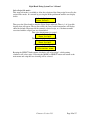
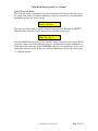
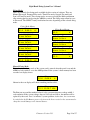
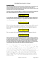
Night Hawk Firing System User’s Manual
Firmware Version 2.53
Page 1 of 37
Night Hawk Firing System User’s Manual
Table of Contents
Features of the Night Hawk Panel................................................................................... 4
A reminder on the safe use of Electronic Pyrotechnic Firing Systems ........................... 5
Night Hawk Firing Panel Controls.................................................................................. 6
Battery/External Power Switch ................................................................................... 6
Panel Lamp On/Off Switch .......................................................................................... 6
Charge Jack................................................................................................................... 6
External Battery Power Binding Posts ....................................................................... 6
ARM Key Switch........................................................................................................... 6
2-Line Text Display....................................................................................................... 6
Mode Button .................................................................................................................. 7
Reset Button .................................................................................................................. 7
Select -/+ Knob .............................................................................................................. 7
Fire Status (1 - 45)......................................................................................................... 7
Firing Status definitions in Status Mode..................................................................... 8
Firing Status definitions in Random Fire Mode ......................................................... 8
Firing Status definitions in Prompted Fire Mode ....................................................... 8
Firing Switch (1 to 45) .................................................................................................. 8
FM Select buttons (A – L) ............................................................................................ 9
Remote Fire Connector ................................................................................................ 9
9 pin Serial Port ............................................................................................................ 9
Built In Functions ............................................................................................................. 9
Digital Voltage Display ................................................................................................. 9
Battery/Power Status Display ...................................................................................... 9
Firing Module Memory ................................................................................................ 9
Show Memory................................................................................................................ 9
Firing Script Memory................................................................................................. 10
Elapsed Timer ............................................................................................................. 10
Night Hawk Firing Panel Operational Modes.............................................................. 11
Power On/Version Display ......................................................................................... 11
Continuity/Status Mode.............................................................................................. 11
Reset Timer –........................................................................................................... 13
Reset Rail Memory – .............................................................................................. 13
Reset Show Memory – ............................................................................................ 13
Reset Fire Script –................................................................................................... 13
Review Show List Sub mode – ............................................................................... 14
Review Script Sub mode –...................................................................................... 15
Create Script Sub mode –....................................................................................... 16
Play Script Sub mode –........................................................................................... 19
Select Script Sub mode – ........................................................................................ 20
Download Script Sub mode –................................................................................. 21
Upload Script Sub mode –...................................................................................... 22
View Timecode Sub mode – ................................................................................... 23
Firing Modes................................................................................................................ 24
Manual Firing Mode............................................................................................... 24
Prompted Fire Mode............................................................................................... 26
Timed Fire Mode..................................................................................................... 28
Stepped Fire Mode.................................................................................................. 30
Firmware Version 2.53
Page 2 of 37
Night Hawk Firing System User’s Manual
Auto Sync’ed Timed Fire Mode............................................................................. 32
Common Timecode problems ................................................................................ 36
Firmware Version 2.53
Page 3 of 37
Night Hawk Firing System User’s Manual
Features of the Night Hawk Panel
•
•
•
•
•
•
•
•
•
•
•
•
•
•
•
•
•
•
•
540 discrete shots, organized as 12 firing modules of 45 shots each.
Continuity and Fired Status for each of the 45 firing circuits
Digital Battery Voltage display with Low Battery warning
100 minute elapsed time display with pause and reset, retained when power is off
Illuminated Pushbutton 1-of-12 selection of Firing Modules
Each selectable Firing Module has a resettable memory of what has been fired
Separately selectable internal battery or external power supply
Detachable panel lamp with On/Off switch
Retain and review history of a fired show by firing order
Arm Tone when panel is switched from safe to ARMED condition
Manual fire mode
Two selectable 550 shot script tables with optional script name display
Prompted fire mode that informs the operator of next shot to be fired
Automated Timed Sequential firing mode
Automated Stepped Sequential firing
Automated Synchronized Time Sequential firing
Easily create a firing order script and use it for shot prompting in Prompted fire
mode, automated timed firing mode, automated stepped firing and automated
Synchronized Timed firing mode.
Splash proof and dust proof firing switches and firing module select switches
Chemical, scratch and burn resistant electrically isolated front panel
Firmware Version 2.53
Page 4 of 37
Night Hawk Firing System User’s Manual
A reminder on the safe use of Electronic Pyrotechnic Firing Systems
Never energize Electronic firing equipment when personnel or spectators
would be jeopardized by unintentional ignition.
Prevent water or conductive liquids or powders from contacting firing system
components (Firing Panel, firing modules, splitters, cable ends etc.)
Never drive over or place heavy objects on firing cables
Do not wrap multiple wiring attached to igniters around conductive supports as
the insulation can be abraded from shells yanking the wires, causing multiple
shorts.
When inserting the igniter wires into the firing module, separate the insulation
and leave less than ¼” copper showing above the connector. Allowing long
copper leads has caused multiple un-intentional firing or shunting.
Always keep the internal batteries charged. All batteries have a self-discharge
rate. It’s much worse if the equipment is left on and put in storage. When the
battery voltage drops below 10.6 volts under light loading on a Lead-Acid cell
battery, it’s damaged and has become un-reliable for Pyrotechnic work.
Period. End of story.
Firmware Version 2.53
Page 5 of 37
Night Hawk Firing System User’s Manual
Night Hawk Firing Panel Controls
Battery/External Power Switch
This power rocker switch located in the upper left-hand corner of the panel is a threeposition illuminated switch. The Center position is Power Off. The Upper position selects
power from the internal battery. The lower position selects power from the External
Battery binding posts. The switch is illuminated when power is present and selected.
Panel Lamp On/Off Switch
This switch controls the detachable panel lamp only when the system is on.
Charge Jack
The charging jack is a P5 jack and is used to charge the internal batteries. It requires a
supply that delivers 12.0 VDC at 1.5 amps. The center pin is positive. The battery
charging circuit will charge the battery even when the Battery/External Power switch is
off.
External Battery Power Binding Posts
There are two binding posts located to the left of the Panel Lamp switch. The red post is
positive and the black post is negative. These binding posts are provided to allow
supplying the panel with 12 volts DC as an alternative to the internal battery supply in the
event that the internal batteries become depleted. The allowable supply range is 11 to 15
volts DC, easily supplied by a car type 12-volt battery. When External power is used, the
firing voltage may be less than the normal +24V range. This is because the internal
battery is used to extend the external power beyond the external supply input voltage.
Applying an external power source with a voltage greater than 20.4 volts in an attempt to
increase the firing voltage will damage the Nighthawk panel.
ARM Key Switch
The ARM key switch is located in the upper left-hand side of the panel, to the right of the
rocker power switch. It is a two-position key lock switch, with OFF and ARM positions.
The key cannot be removed in the ARM position. When the system is powered and the
ARM switch is turned to the ARM position, the ARM status light is illuminated. A
warning tone will sound for 1.5 seconds to alert the operator that the panel has turned on
the firing voltage supply. The ARM switch places the system into one of the firing
modes, which means that a firing circuit can be activated because the firing voltage
supply has been enabled. From the initial ARM state, additional firing modes can be
accessed through the Mode and Select buttons. The Manual Random Fire Mode is the
first ARMED firing mode presented after arming the system.
2-Line Text Display
The text display is a monochrome LCD, 16 characters long by 2 lines. It is backlit to
allow viewing in low light conditions. It provides information on the currently selected
mode of operation, access to the system menus and warnings when they occur. The top
line typically displays text legends indicating the specific numeric data that appears on
the bottom line directly below it means, or in other cases, it may show a menu selection
option. The LCD display cover is Plexiglas and should only be cleaned with mild soap
Firmware Version 2.53
Page 6 of 37
Night Hawk Firing System User’s Manual
and water. Never use alcohol or any industrial solvent to clean the front of the firing
panel.
Mode Button
To the right of the text display is a vertical column of 3 pushbuttons. The top button is the
Mode button. This pushbutton switch accesses a mode sensitive menu through the 2-line
text display. The options displayed in the text display depend on the current mode of
operation. If a displayed option is not selected in 5 seconds, the display will revert to the
normal display for the current mode.
Reset Button
To the right of the text display is a vertical column of 3 pushbuttons. The middle button is
the Reset button. This pushbutton switch accesses a mode sensitive RESET menu
through the 2-line text display. If a displayed option is not selected in 5 seconds, the
display will return to the normal display for the mode currently in use.
Select -/+ Knob
To the right of the text display is a vertical column of 3 button/controls. The knob at the
bottom of the column is the Select control. It acts as both a pushbutton and rotary input
device. This pushbutton knob control is mode sensitive and is used by the panel menu
system and the script editing modes. It is used to change to/and select the option
displayed in the text display. Rotating the knob clockwise has the effect of increasing
numbers, and counter-clockwise of decreasing numbers.
When the firing panel is at the top level menu in unarmed state, rotating the SELECT
knob clockwise will advance thru the MODE menu selections. But rotating the SELECT
knob counter-clockwise will advance thru the RESET menu selections. Pressing the knob
with a MODE or RESET menu choice present will initiate that choice. The SELECT
knob doesn’t allow menu selection when the ARM switch is on. The rotary actions are
reserved for other features in the firing modes.
In some of the menu modes the knob will have additional effects. In FIRE modes the
SELECT knob will have other effects.
Fire Status (1 - 45)
The Cue status indicators show the current continuity and status of each of the 45 firing
circuits of the selected Firing Module. They use two-color LED lamps for long life and to
provide more information than a single color could. There are 4 basic conditions that are
displayed, with additional advanced status possible. The continuity circuit is the green
side of a two-color LED with a current limiting resistor. It has a 1/6th duty cycle to
conserve battery power. The red side of the two-color LED is directly controlled by the
panel electronics and is used to communicate captured status of various kinds.
The 1st condition for the indicator is off completely, which occurs when the system is off
or if there is no igniter present in the selected firing circuit and the circuit hasn’t been
activated since the last show or rail memory reset.
Firmware Version 2.53
Page 7 of 37
Night Hawk Firing System User’s Manual
The 2nd condition for the indicator is green, showing that there is some type of electrical
connection present in the firing circuit. The brightness of the indicator provides some
additional information on the relative resistance of the circuit.
The 3rd condition for the indicator is a red color, showing that the firing circuit for the
selected Firing Module has been activated since the last rail or show memory reset.
The 4th condition for the indicator is both green and red, indicating that the igniter is still
providing an electrical connection somehow after being fired.
The third and fourth conditions are modified by having the red color flashing, showing
the last fired Cue for the selected firing module in Random Manual Fire mode, or the
next to be fired in Prompted Manual Fire mode. The way to determine whether the status
is flashing for last fired, or next fired, is to look at the 1st line of the text display and
observe whether the word FM, Last or Next is shown at the end of the top line.
Firing Status definitions in Status Mode
Condition Color
Description
1
Off
Not fired, no continuity
2
Green
Not fired, continuity
3
Red
Fired, no continuity
4
Green + Red
Fired, continuity. Possible error, shorted igniter?
Firing Status definitions in Random Fire Mode
Condition Color
Description
1
Off
Not fired, no continuity
2
Green
Not fired, continuity
3
Red
Fired, no continuity
4
Green + Red
Fired, continuity. Possible error, shorted igniter?
5
Flashing Red Last fired Cue of selected rail.
6
Green +
Last fired Cue of selected rail, system armed similar to
Flashing Red condition 4.
Firing Status definitions in Prompted Fire Mode
Condition Color
Description
1
Off
Not fired, no continuity
2
Green
Not fired, continuity
3
Red
Fired, no continuity
4
Green + Red
Fired, continuity. Possible error, shorted igniter?
5
Flashing Red Next Cue to be fired, problem with no continuity.
6
Green +
Next fire que, with continuity.
Flashing Red
Firing Switch (1 to 45)
There are 45 firing switches arranged in 5 rows of 9 switches. The switch locations are
numbered 1 thru 45 on the panel, with the number positioned between the firing switch
and the associated firing status. Each switch is connected to a firing circuit. A firing
switch will only fire an igniter when the ARM key switch is turned to the ARM position.
Firmware Version 2.53
Page 8 of 37
Night Hawk Firing System User’s Manual
FM Select buttons (A – L)
The Firing Module select switches are in a vertical column of 12 round illuminated
pushbutton switches located on the right side of the panel adjacent to the associated firing
module connector. Only one Firing Module may be selected at a time. When a desired
firing module is selected, the switch illuminates and the memory for what previous
activations of the firing switches is recalled and displayed on the fire status lights and the
text display when appropriate. At the same time the FM letter is updated on the right
hand side of the bottom line of the text display.
Remote Fire Connector
This connector is positioned directly below the power rocker switch. Not used for manual
fire modes. The Remote Fire Control is used to support automated firing. The remote fire
control has a hold fire safety and a fire trigger. When the Automated firing modes are
used, the remote fire control must be installed. Automated firing will only occur when the
Remote Hold Fire is held depressed. When using an automated firing mode, the show
timer will be paused whenever the Hold Fire switch is released.
9 pin Serial Port
This DB9 connector is used to transfer firing scripts to and from the firing panel. This
serial port is also used by panels equipped with the SYNC mode software for the
reception of Timecode. An external Timecode modem is required to convert the analog
FSK Timecode signal to the serial format used by the Nighthawk panel.
Built In Functions
Digital Voltage Display
Panel system voltage is displayed from 0.0 to 20.4 volts with 0.1-volt resolution. When
the voltage drops below 10.7 volts, a low voltage message will appear in the voltage
display area.
Battery/Power Status Display
The left side of the top line of the text display shows the power source status when the
power switch is set on either Battery or External. If the battery charger is plugged into the
charging jack, the Status will indicate whether the batteries are charging or full. The
statuses are “Batt”, “Chrg”, “Full”, “Ext “ and “Ext+”. The “Ext+” status indicates that
the batteries are charged and that the battery charger is plugged into the charging jack.
Firing Module Memory
Each of the 12 selectable firing module connectors has a memory associated with it that
tracks firing history. The operator can individually reset each firing module history. The
information saved is the accumulated fired shots for that module and the last fired shot.
This information is retained when the panel is turned off, as long as the power is not
turned off while in FIRE mode. This fired information is used for the red fire status
indicators in the different modes of operation.
Show Memory
This memory captures a history of what shots have been fired by time and module. The
operator can reset it. It also saves the elapsed time when the panel is switched from FIRE
Firmware Version 2.53
Page 9 of 37
Night Hawk Firing System User’s Manual
mode to Status mode. This information is retained when the panel is turned off, as long as
the power is not turned off while in FIRE mode.
Firing Script Memory
The firing script memory is a list for shots that has been entered into the panel memory. It
is similar to the Show memory, but is used by the scripted fire modes to help the operator
follow a preset firing order. Each module’s shots are also accumulated when the operator
captures the firing script using the panel. This information is retained when the panel is
turned off. The shot number starts at 1 and goes to a maximum of 550. There are two
selectable script memories. There is a script naming feature that is only available when a
script is downloaded thru the serial port that allows easier identification of the script that
is selected.
Elapsed Timer
There is an elapsed time function that is present in the panel that tracks the time from an
initiating event. The initiating event is always a firing switch activation. The timer is
paused when the mode that it was running in is changed. Additionally, when using auto
timed fire modes, the Hold Fire switch will influence the Timer’s run/pause behavior.
The maximum timer value is 99 minutes 59.9 seconds with 0.1-second resolution.
Firmware Version 2.53
Page 10 of 37
Night Hawk Firing System User’s Manual
Night Hawk Firing Panel Operational Modes
Power On/Version Display
When the panel is turned on, it will display the Version number of the internal software
for three seconds, and then it goes to the Continuity mode display.
Time = 0
Time not 0
Continuity/Status Mode
This mode is the default mode of operation when the firing system is not ARMED. In this
mode, the firing system displays the continuity status and the fired status of each of the
firing switches 1- 45 circuits’ for each selected Firing Modules connectors. The text
display shows the battery voltage, elapsed time and the selected firing module. If the
elapsed time is 0:00.0, the time field is cleared to blank. The firing module memory for
the selected display is reflected on the firing status indicators, but without the last fired
information.
There are two menus available in this mode, the Mode menu options and the Reset menu
options. If the menu option presented is not selected within 5 seconds, the display will
return to the default condition showing the voltage, elapsed time and the selected rail.
Firmware Version 2.53
Page 11 of 37
Night Hawk Firing System User’s Manual
Status Mode Menus
Status Reset Menus
#
!
"
! $ %
!
#
,
! $ %
#
!% &
! $ %
!
#
$
! $ %
'
#
!% &
! $ %
!
#
#$ ( !% &
#
! $ %
!
#
!
(,
(,
! $ %
!%
! $ %
& ,
! $ % !% &
#
! $ %
)
#
+&$
#
#
$
* !%
! $ %
&
* !% &
! $ %
% *
! $ %
Firmware Version 2.53
Page 12 of 37
Night Hawk Firing System User’s Manual
Reset Timer –
The RESET Timer menu selection will clear the Show Timer to 0:00.0. It will not affect
any other system settings or memory. No confirmation other than pressing the SELECT
knob is required to perform this action. It is also allowed in the Manual Fire mode.
Reset Rail Memory –
The RESET Rail Memory menu selection has the effect of wiping out the pin fired
history of the currently selected rail A-L and in addition clearing the Show Timer to
0:00.0. No confirmation other than pressing the SELECT knob is required to perform this
action. It is also allowed in the Manual Fire mode.
Reset Show Memory –
The RESET Show Memory menu selection has the effect of wiping out the pin fired
history of all the rails A-L and in addition clearing the Show Timer to 0:00.0 and show
history memory. No confirmation other than pressing the SELECT knob is required to
perform this action. It is also allowed in the Manual Fire mode.
Reset Fire Script –
The RESET Fire Script menu selection has the effect of wiping out the currently selected
script plus the pin fired history of all the rails A-L and in addition clearing the Show
Timer to 0:00.0 and show history memory. Additional confirmation other than pressing
the SELECT knob is required to perform this action. A It is not allowed in the Manual
Fire mode.
The following steps are required to reset the current script:
Press the RESET button until the display shows:
!
#
!%
! $ %
& ,
Then press the Select pushbutton. The display will change to:
!
-.
/
!%
0
& ,
12!
Rotate the SELECT knob clockwise. The display will change to:
!
#
!%
!2"2'
& ,
12!
Press the SELECT knob. This will clear the script memory and the script firing module
memories. If the SELECT knob is pressed while “ -. /
0
12!3 is showing,
the script will not be erased.
Firmware Version 2.53
Page 13 of 37
Night Hawk Firing System User’s Manual
Review Show List Sub mode –
This status sub mode is available to allow review of the fired show history. It is accessed
by pressing the Mode pushbutton until the text display shows:
!
"
! $ %
#
Then press the Select/- pushbutton to enter the review show sub mode. This is the initial
display of the review show list mode:
!
(
$ 4
The value of Total can be 0 to 550. It depends on what was fired by the operator. Pressing
the Reset/+ pushbutton will advance the display to the first entry in the list.
Total = 0
!
5
Total not 0
"
5 55 5
!
"
5 55 5
While in this mode, the Reset/+ pushbutton advances the display thru the captured show
memory, and the Select/- pushbutton steps backward thru the show memory. When the
end of the captured memory is reached, the display shows:
2 * 0 !
5 66 6 6
"
The actual second line will reflect what the last entry of the show that was captured was.
When a fire status LED is flashing red, it indicates the fired Cue in the history list
associated with the elapsed time. As the list is stepped thru, the previously fired Cue turns
red. If a different firing module is required for the current Cue, it is automatically
selected.
Firmware Version 2.53
Page 14 of 37
Night Hawk Firing System User’s Manual
Review Script Sub mode –
This status sub mode is available to allow review of the captured fire script. It is entered
by pressing the Mode pushbutton until the text display shows:
!% &
! $ %
#
Then press the SELECT knob to enter the Review Script sub mode. This is the initial
display of the review fire list mode:
!
!%
$ 4
&
Where Total is the number of captured entries in the firing script from 0 to 540. Rotating
the SELECT knob clockwise advances thru entries in the script.
Total = 0
!
Total not 0
7
5
!
7
5 55 5
5 55 5
While in this mode, rotating the SELECT knob advances and steps the display backward
thru the captured firing script memory. When the end of the captured memory is reached,
the top line of the display shows:
2 * 0 !
5 66 6 6
"
The bottom line contains whatever was the last captured shot entry.
When a fire status LED is flashing red, it indicates the Cue that was fired at the displayed
time. The correct Rail button (A-L) will illuminate to show which module was fired.
Pressing a Rail switch (A-L) will display all the pins that are scripted for that module.
The script entry will be usurped until the SELECT knob is rotated, returning to the recent
entry in the script.
Firmware Version 2.53
Page 15 of 37
Night Hawk Firing System User’s Manual
Create Script Sub mode –
This status sub mode is available to allow the creation of the firing script list used by the
scripted firing modes. These include Prompted Fire, Timed Fire, Stepped Fire and
Sync’ed Fire modes. It is entered by pressing the Mode pushbutton until the text display
shows:
'
!% &
#
! $ %
Then press the SELECT knob to enter the create fire list sub mode. This is the initial
display of the create fire list mode if the fire script memory has been reset. There are two
ways to enter a script into memory. The default method is to toggle the firing switches
with the expected timing as if firing the show. The other method, while more involved,
allows greater control over the individual shots. It is uses the SELECT rotary knob to set
the fire timing. This is the default display for timer captured scripting.
!
"
5 55 5
5
While in this mode, any activation of the firing switches will add an entry to the fire
script. The captured entry contains the firing switch, the firing module and the firing
time. If the show timer is paused, it will begin to run. To remove the last entry in the list,
press the RESET pushbutton. This also rolls back the elapsed time to the previous entry’s
captured time. To exit this mode, press the Mode pushbutton. When the mode is exited,
the last entry is saved in long-term storage.
To create a new firing script, first reset the existing firing script memory by pressing the
RESET pushbutton until the display shows:
!
#
!%
! $ %
& ,
Then press the Select pushbutton. The display will change to:
!
-.
/
!%
0
& ,
12!
Rotate the SELECT knob clockwise. The display will change to:
!
#
!%
!2"2'
& ,
12!
Press the SELECT knob. This will clear the script memory and the script firing module
memories.
Next, press the Mode pushbutton until the Create Fire List option shows in the display
and press the Select pushbutton to enter it.
The display shows a shot number of 0 and the timer is paused, waiting for the 1st firing
event. Select the firing module that contains the 1st Cue and activate the firing switch of
Firmware Version 2.53
Page 16 of 37
Night Hawk Firing System User’s Manual
that Cue. The shot number will advance to 1 and the elapsed time starts running.
Selecting the correct firing module and entering the Cue is just like firing a show in
manual firing mode, only the panel is not armed. The script firing module memory retains
the firing switches activated for each module in this mode along with what was last fired,
until it is cleared using the RST firing script option.
When the script has been captured, the mode can be exited by pressing the Mode
pushbutton. When this is done, the end point of the script is saved in storage and will be
remembered if panel power is turned off.
If a firing script has already been partially captured, re-entering the create mode will go
to the end of the existing script and allow the operator to extend it.
Create Script Manual Time entry
The alternate method of capturing a script requires more manual effort, but allows greater
control in creating a script. It is enabled after entering Create Script mode by pressing the
SELECT knob while the show timer is paused. It is indicated when the top line displays
Time instead of Timer. Here is an example:
!
5
"
5 55 5
Pressing the SELECT knob again will switch to the timer captured scripting mode. So
use the top line of the text display to determine which mode the script is being captured
in.
After entering Create Script mode, press the SELECT knob until the top line displays “
Shot Time Last”. If the script is empty, the bottom line will show “ 0 0:00.00 A”
where A is the rail/module selected. Toggling any one of the firing switches 1-45 will
enter that firing pin/module combination along with the displayed time into the firing
script and advance the shot count by one. The time will advance by a minimum of 0.1
seconds. Rotating the SELECT knob clockwise will advance the time in increments of
0.1 seconds. Rotating the knob counter-clockwise will decrement the time by 0.1 seconds
until the previous time + 0.1 seconds is reached. This is to prevent entering more than one
firing pin per shot. This is an arbitrary limit to avoid trying to fire more than one rail
module at the same time. If multiple pins are required to fire on the same module at the
same time, then the script must be downloaded instead of manually entered.
There is one feature available in the manual script capture mode that the operator can
take advantage of for making script entry easier. It uses a time offset value calculated
from the previous captured shot to advance the new time. To observe and understand this
feature, start with an empty script, toggle to time capture mode and then rotate the
SELECT knob to display a time of “0:03.0” in the text display on the bottom line.
!
5
5 5
"
5
Firmware Version 2.53
Page 17 of 37
Night Hawk Firing System User’s Manual
Press rail button A to choose the first Rail and then toggle firing switch 1. The status
indicator for 1 should start flashing red and the text display will change to:
!
5 5
"
5
Notice that the time advanced by 3.0 seconds, which was the time difference from the
previous time to the captured time. Toggle firing switch 2 to capture the next shot. The
status indicator for 2 will start to flash red and the indicator for 1 will become solid red.
The text display will show:
!
"
5 56 5
Again the time advanced by the difference between the previous time and the captured
time. To change the time offset, just rotate the SELECT knob. The minimum time is 0.1
seconds. If the 1st shot had been captured at 0:00.0 instead of 0:03.0 then the calculated
time offset would be the minimum offset of 0.1 seconds for the next shot, and each
follow on shot would be advanced by 0.1 seconds unless the time was changed using the
SELECT knob. In this fashion, a series of shots can be rapidly entered with equal time
spacing.
Script editing is kept to a minimum, with only the ability to delete the last entry by
pressing the RESET button.
Exiting and re-entering the Create Script mode will allow the building of a script in
stages. This avoids the unpleasant experience of inadvertently turning off the panel
without saving the entered script thru the MODE button. The MODE button must be
pressed to save the script or any additions to it.
Firmware Version 2.53
Page 18 of 37
Night Hawk Firing System User’s Manual
Play Script Sub mode –
This status sub mode is available to allow the dynamic review of the firing script list used
by the scripted Fire modes. It is entered by pressing the Mode pushbutton until the text
display shows:
#$ ( !% &
#
! $ %
Then press the SELECT knob to enter the play fire list sub mode. This is the initial
display of the create fire list mode if the fire script memory has been reset.
!
!% &
$ 4 777
Pressing the SELECT knob or toggling a firing switch will start the script running in Play
mode. Pressing the SELECT knob while the script is playing will restart the script
playing from the beginning.
Firmware Version 2.53
Page 19 of 37
Night Hawk Firing System User’s Manual
Select Script Sub mode –
This status sub mode is available to allow the selection of the firing script list used by the
scripted Fire modes. It is entered by pressing the Mode pushbutton until the text display
shows:
! $ % !% &
#
! $ %
Then press the Select knob to enter the Select Script sub mode. There is 1 of 4 possible
displays that will appear. The top line will be the same, but the bottom line will display
either the default script name for the currently selected script, or a 16 character name
associated with the script if one was downloaded.
This is the default name for script 1.
/
! $ %
8
!
!% &
This is the default name for script 2.
/
! $ %
8
!
!% &
Alternate name for scripts 1 or 2
/
! $ %
8
%
%
Rotating the SELECT knob counter-clockwise will select script 1, while rotating
clockwise will select script 2. Pressing the MODE or SELECT button will return to the
main menu and script that was showing will be selected.
Firmware Version 2.53
Page 20 of 37
Night Hawk Firing System User’s Manual
Download Script Sub mode –
This status sub mode is available to allow the importation of the firing script list used by
the scripted Fire modes. It is entered by pressing the Mode pushbutton until the text
display shows:
)
$ * !% &
#
! $ %
Then press the Select knob to enter the Download Script sub mode. The script that will be
replaced is shown on the bottom line of the text display.
)
!
$
* !%
!% &
&
Rotating the SELECT knob counter-clockwise or clockwise will select one of the two
available scripts to load from the serial port. When the SELECT knob is pressed, the
panel will begin reception of the script being transferred.
!
"
) $*
While the download is taking place, the status and rail lamps will illuminate for each fire
record received. If the download has to be aborted, press the MODE button to exit back
to the main menu. Otherwise a successful download will show something like:
2 * * "
9/$( .
) $*
*
The bottom line will show a script name if one was downloaded with the script. This
name will be displayed when the script is selected, reviewed or when setting up to fire for
one of the scripted fire modes.
To download an additional script to the alternate table, the SELECT knob can rotated. If
the SELECT knob is pressed after the “Ended List Dnld.” Message is displayed, the panel
will begin waiting for the new script and will display the “Start List Dnld.” message.
When done downloading, press the MODE button to exit the Download Script sub-mode.
If the current script is reset at any time, the downloaded script name will revert to the
default script name i.e. Show Script1 or Show Script2. Resetting the show scripts is such
a potentially dangerous action, it requires an additional confirmation step to perform it.
If the download completes, but the “Ended List Dnld.” Message is not displayed, then
exit the Download Script mode by pressing the MODE button and re-enter the mode and
try again. This can sometimes occur if there were partial fire records received from a
previous aborted download attempt.
Firmware Version 2.53
Page 21 of 37
Night Hawk Firing System User’s Manual
Upload Script Sub mode –
This status sub mode is available to allow the transference of the firing script list used by
the scripted Fire modes to another Nighthawk system. It is entered by pressing the Mode
pushbutton until the text display shows:
+&$
#
* !% &
! $ %
Then press the Select knob to enter the Upload Script sub mode. Rotating the SELECT
knob will allow selection of either one of the two available show scripts.
! $ %
!
!%
!
&
*
When the SELECT knob is pressed, the currently shown script will be sent out the RS232
port in the format used for downloading scripts to a Nighthawk. If another Nighthawk is
connected to this panel using a NULL MODEM cable and set to download a script, it will
receive the script being sent. In this way, multiple Nighthawks can share the same scripts,
i.e. a backup machine.
Firmware Version 2.53
Page 22 of 37
Night Hawk Firing System User’s Manual
View Timecode Sub mode –
This status sub mode is available to allow the viewing of Timecode. This is helpful in
testing the Timecode transport and quality of signal intended for SYNC’ED TIMED Fire
mode. It is entered by pressing the Mode pushbutton until the text display shows:
% *
! $ %
#
Then press the Select knob to enter the View Timecode sub mode. The Text window will
show this display:
:
0
!( %
5 55 5
The top line indicates that the panel is monitoring the incoming serial stream on the DB9
serial connector and waiting for the 1st occurrence of a valid Timecode record. The
bottom line shows the Timecode offset that is added or subtracted from the Timecode
stream. This value will carry over into the SYNC’ED FIRE mode. It does get reset to 0
whenever the panel is turned off and back on. This is done deliberately to prevent unintentional offsetting of Timecode for SYNC’ED FIRE.
When valid Timecode is being received by the panel, the top line of the text display will
show two values, an error count and a converted time derived from the received
Timecode records. Normally the top line time value will advance in 1/10th second
increments. If an error occurs in the Timecode record, the 1st number on the top line will
increment. This allows an estimate of the quality of the Timecode channel from the
analog source thru to the modem and on to the Nighthawk panel.
5
5 55 5
5 55 5
To reset the error and top line time values, press the RESET button. If the MODE button
is pressed, the View Timecode sub-mode will be exited and return to the main menu
level.
To adjust the Timecode offset in View Timecode mode, press and hold in the SELECT
knob and then rotate it clockwise or counter-clockwise while still depressing the knob.
The bottom line time value will increment or decrement by 0.1 second for each click. A
plus or minus sign will indicate a positive or negative Timecode offset.
Firmware Version 2.53
Page 23 of 37
Night Hawk Firing System User’s Manual
Firing Modes
There are currently five firing mode available for this version of software. They are
Manual Fire mode, Prompted Fire mode, Timed Fire mode, Stepped Fire mode and
Sync’ed Time Fire mode. These firing modes are accessed using the Mode pushbutton
after entering the fire mode using the ARM key switch. The firing script cannot be reset
in Fire mode. The SELECT rotary knob behavior varies depending on the selected firing
mode.
Firing Mode Menus
"
5 55 5
Firing Reset Menus
# - # 2) ; 2,
#
! $ %
; 2) ; 2,
#
! $ %
! 2##2) ; 2,
#
! $ %
!
#
,
! $ %
!
#
$
! $ %
!
#
!
(,
(,
! $ %
!1 '<2) ; 2,
#
! $ %
"
5 55 5
Manual Firing Mode
This is the default firing mode of the system, and is entered when the panel is on and the
ARM key lock switch is set to the ARM position. If the systems’ show memory has been
reset the text display shows:
"
5 55 5
Otherwise the text display will show something similar to this:
"
5 =
The Batt text area and the number below it is the system main power voltage with 0.1
volt resolution. If the system voltage drops to 10.6 volts and lower, the number will be
replaced by the word “Low” to indicate a system problem. At that time, the system must
be switched to the Ext Battery power selection on the Power switch or the system must be
charged to avoid damage to the internal battery.
Firmware Version 2.53
Page 24 of 37
Night Hawk Firing System User’s Manual
The Time text area shows the elapsed time from when the first Cue was fired until the
timer was stopped by turning the ARM key switch to the OFF position. The timer
resolution is in 0.1-second increments.
The Last text area shows the last fired Cue of the currently selected Firing Module. If
there as been any Cue fired from the currently selected Firing Module, the last fired Cue
will be flashing at a 5 times a second rate. This position of the top line will show one of
three different words, “FM”, “Last” or “Next”. “FM” stands for Firing Module, and
usually indicates that the panel is in the Continuity/Status mode. “Last” usually indicates
that the flashing firing status LED is the last fired que. “Next” in this area is reserved for
Prompted Fire Mode, to indicate that the flashing status LED is the Cue to be fired next.
The number next to the letter (A-L) designates the lowest numbered Cue that is flashing.
When entered from the Status mode, the elapsed time will be paused. It will start or
continue as soon as a firing switch is activated, and will run until the operator turns the
ARM switch to OFF or the power switch is turned off. If the power switch is turned off
while the panel is still in ARM and the timer is running, the latest elapsed time will not be
saved! Always try to turn the panel ARM key switch to OFF before turning the panel
power off.
Each time a firing switch is activated, a record is captured of the elapsed time, Cue
number and firing module. These captured events make up a show history that is retained
in memory even when power is turned off. This show history can later be reviewed.
The Firing Module can be selected and activated by pressing the desired Firing Module
selector switch, which will then display the status history of that Firing Module. As
mentioned above, if any of the cues have been fired from the Firing Module, the last fired
Cue is flashing red to make it easier to locate quickly.
Firmware Version 2.53
Page 25 of 37
Night Hawk Firing System User’s Manual
Prompted Fire Mode
This is an advanced Manual fire mode that has the additional feature of suggesting to the
operator the firing order of the show, derived from a firing order script that was
previously entered into the internal memory of the firing system. This mode only uses the
script firing order, not the time for the prompting.
The mode is entered is when the ARM key is turned and the system placed in manual fire
mode and the MODE button is pressed once to cause the text display to show:
# - # 2) ; 2,
#
! $ %
To select this mode, the SELECT knob is pressed, causing the system to enter the mode
and display the first suggested firing Cue as a red flashing status indicator. If there is no
entered firing script present the text display will show:
!%
& >
If there is a firing script in memory, the bottom line will have the same display except for
the last 3 characters which will show a number from 1 to 45 and a letter from A-L to
indicate which Cue on what FM is the one to be activated by toggling the appropriate
firing switch.
!
7
5 55 5
This is an example of the last possible entry and display of a programmed firing list.
!
5 66
6 6
7
"
Once the suggested Cue has been fired and released, the system will advance to the next
Cue in the script. The time display will begin to run. The system will automatically select
the appropriate Firing Module if it isn’t the current Firing Module each time it advances.
The script will not advance if the suggested Cue is not fired, unless the operator forces
the system to skip the entry by rotating the SELECT knob clockwise. The previous entry
can be repeated if the operator rotates the SELECT knob counter-clockwise.
If there is a need to deviate from the firing script, a Cue can be fired out of order on the
currently selected Firing Module, or from a different Firing Module by selecting it using
buttons A-L. Press the MODE pushbutton to return to the currently suggested Cue. While
out-of-script firing is taking place, the top line of the text display will show Last instead
of Next to show that the Prompted firing is temporarily suspended. If a shot on the
currently selected firing module is fired out of order without changing firing modules and
the top line still shows “!
7 3, then the fired Cue will not flash.
Instead, the next suggested Cue would continue to flash until it is fired. If the firing
module is changed by the operator from the panel selected firing module, the top line
changes to “!
"
3 and the flashing firing status indicates last fired
instead of next fired.
Firmware Version 2.53
Page 26 of 37
Night Hawk Firing System User’s Manual
Normal Prompted Fire
!
7
Prompted Fire
Temporarily Diverted
!
"
To pause the Prompted Fire Mode for any reason, turn the ARM key switch to OFF. To
resume the Prompted Fire Mode at the point where the show left off, re-enter the
Prompted Fire Mode by pressing the MODE button and then the SELECT knob before
any fire switches are activated. The fire script will be at the shot that was last displayed.
If the show needs to be restarted, the show memory must be reset. Alternately, the script
can be advanced or backed up to any point within the script by using the SELECT knob.
When the last entry in the firing script has been fired, the text display will show
something similar to the following:
?2 *
5
0 !
=
2
At the end of the firing script, the shot number stops advancing but the timer will
continue to run until the ARM switch is turned to OFF or the time reaches 99:59.9.
If any shots need to be fired out of order, or if there are additional shots that weren’t
entered into the firing list, they can be fired at any time by selecting the necessary firing
module and activating the appropriate firing switch. To return to the firing order, press
the Mode, Select or Reset pushbuttons, which will restart the current entry in the firing
list with the correct firing module selected for that shot.
Firmware Version 2.53
Page 27 of 37
Night Hawk Firing System User’s Manual
Timed Fire Mode
This is a basic automated sequential timed firing mode that uses time as the event trigger
to fire a preprogrammed firing script. The remote fire control is used to start and execute
the firing mode. The Remote Hold fire switch must be held depressed for the firing script
to be executed before, during and after the Remote Fire trigger is pressed. While in this
firing mode, the Cue fire switches and the module selector switches on the panel are
disabled and have no effect on the fire program.
The time field of the shot entry determines the time to fire the pending shot entry. Each
shot entry contains the selected firing module, the time and at least one Cue to be fired
when the time matches the running elapsed timer. The shot entries are executed in the
order they appear in the firing script.
The mode is entered is when the ARM key is turned and the system placed in manual fire
mode and the MODE button is pressed twice to cause the text display to show:
; 2) ; 2,
#
! $ %
Once the Select knob is pressed, the display will show one of the following:
Remote Hold fire not depressed
#
$*
$ 4 777
Script total = 0
>
Note: xxx is the actual number of shot
entries in the firing script.
Remote Hold fire depressed
!%
& >
*
Mode reverts to Manual fire display
after 2 seconds
/ 0
$ 4 777
Display changes to show default timed
display after1.25 seconds
"
5 55 5
*
/ 0
5 55 5
The firing mode is started when the Remote Fire trigger is pressed while the Remote
Hold fire switch is held depressed. The elapsed timer begins to run, and if there is a shot
entry that corresponds to the beginning time, it is fired. The elapsed timer will only run
when the Remote Hold fire switch is held depressed. As soon as the Remote Hold fire
switch is released, the elapsed timer will stop running and the firing mode is paused.
The text display has the format where the top line shows the internal system voltage, the
running elapsed timer and the last fired Que. The bottom line shows the next shot event
number, the next shot event time and the next shot event Que. Something like the
following:
6
=
The highlighted area of the top line shows the elapsed timer display field that shows the
advancing show time.
When the Remote Hold fire switch is released while the fire program is running, the
elapsed timer is stopped and the text display shows something similar to the following:
#
$*
>
=
Firmware Version 2.53
Page 28 of 37
Night Hawk Firing System User’s Manual
When the Remote Hold fire switch is again depressed while the fire program is paused,
the elapsed timer is still paused and the text display shows something similar to the
following:
* / 0
=
Switching to this after 1.25 seconds:
6
'
=
Pressing the Remote Fire trigger while the Remote Hold fire switch is still held depressed
will start the fire program running at the point it was paused.
Shot events in the fire program may be repeated or skipped over only while the timed
firing mode is paused by releasing the Remote Hold fire switch. This is accomplished by
turning the SELECT knob. When a shot event is selected using the SELECT knob, the
elapsed timer is updated to the pending time field of the new shot event minus 0.1
seconds. This is to allow the operator to start the fire program at a predictable point in the
show.
Another feature that is often overlooked is the ability to adjust running time by pressing
in the SELECT knob and rotating it while depressed. This will advance or retard the
show time in 1/10th second increments per click. This would be used if the operator
noticed that the pyrotechnic effects were off by a small amount and wanted to correct for
it.
Firmware Version 2.53
Page 29 of 37
Night Hawk Firing System User’s Manual
Stepped Fire Mode
This is a basic automated sequential stepped firing mode that uses the Remote Fire trigger
as the event trigger to fire a preprogrammed firing script. The remote fire control is used
to execute the firing mode. The Remote Hold fire switch must be held depressed for the
firing script to be executed before, during and after the Remote Fire trigger is pressed.
While in this firing mode, the Cue fire switches and the module selector switches on the
panel are disabled and have no effect on the fire program.
The shot number field of the shot entry determines the order to fire the pending shot
entry. Each shot entry contains the selected firing module, the time and at least one Cue
to be fired when the time matches the running elapsed timer. The shot entries are
executed in the order they appear in the firing script with each press of the Remote Fire
trigger.
The mode is entered is when the ARM key is turned and the system placed in manual fire
mode and the MODE button is pressed three times to cause the text display to show:
! 2##2) ; 2,
#
! $ %
Once the Select knob is pressed, the display will show one of the following:
Remote Hold fire not depressed
#
$*
$ 4 777
Script total = 0
>
Note: xxx is the actual number of shot
entries in the firing script.
Remote Hold fire depressed
!%
& >
Mode reverts to Manual fire display
after 2 seconds
"
5 55 5
!
&& * / 0
$ 4 777
Display changes to show default timed
display after1.25 seconds
5 55 5
5 55 5
The firing mode is started when the Remote Fire trigger is pressed while the Remote
Hold fire switch is held depressed. The elapsed timer begins to run, and the shot entry
that corresponds to the beginning shot number is fired. The elapsed timer will only run
when the Remote Hold fire switch is held depressed. As soon as the Remote Hold fire
switch is released, the elapsed timer will stop running and the firing mode is paused.
The text display has the format where the top line shows the internal system voltage, the
last fired elapsed time and the last fired Que. The bottom line shows the next shot event
number, the current elapsed time and the next shot event Que. Something like the
following:
6
=
The highlighted area of the bottom line shows the elapsed timer display field that shows
the advancing show time.
When the Remote Hold fire switch is released while the fire program is running, the
elapsed timer is stopped and the text display shows something similar to the following:
Firmware Version 2.53
Page 30 of 37
Night Hawk Firing System User’s Manual
#
$*
>
=
When the Remote Hold fire switch is again depressed while the fire program is paused,
the elapsed timer is still paused and the text display shows something similar to the
following:
! && * / 0
=
Switching to this after 1.25 seconds:
6
'
=
Pressing the Remote fire trigger while the Remote Hold fire switch is still held depressed
will start the fire program running at the point it was paused.
Shot events in the fire program may be repeated or skipped over only while the stepped
firing mode is paused by releasing the Remote Hold fire switch. This is accomplished by
rotating the SELECT knob. This is to allow the operator to start the fire program at a
predictable point in the show.
Firmware Version 2.53
Page 31 of 37
Night Hawk Firing System User’s Manual
Auto Sync’ed Timed Fire Mode
This is an advanced automated sequential timed firing mode that uses an externally
delivered time record to set the internal firing time which then gets used as the event
trigger to fire a preprogrammed firing script. The remote fire control is used to set and
arm the firing mode. The Remote Hold fire switch must be held depressed for the firing
script to be executed before, during and after the Remote Fire trigger is pressed. While in
this firing mode, the Cue fire switches and the module selector switches on the panel are
disabled and have no effect on the fire program.
The time field of the shot entry determines the time to fire the pending shot entry. Each
shot entry contains the selected firing module, the time and at least one Cue to be fired
when the time matches the running elapsed timer. The shot entries are executed in the
order they appear in the firing script.
The mode is entered is when the ARM key is turned and the system placed in manual fire
mode and the Mode button is pressed four times to cause the text display to show:
!1 '<2) ; 2,
#
! $ %
Once the Select switch is pressed, the display will show one of the following:
Remote Hold fire not depressed
#
!
$*
!% &
Script total = 0
>
Note: xxx is the actual number of shot
entries in the firing script.
Remote Hold fire depressed
!%
& >
Mode reverts to Manual fire display
after 2 seconds
"
5 55 5
!( %< * / 0
!
!% &
Display changes to show default sync
display after trigger is pulled
:
0
!( %
5 55 5
The firing mode is armed when the Remote Fire trigger is pressed while the Remote Hold
fire switch is held depressed. The elapsed timer does not begin to run until a valid
Timecode record is decoded. It will wait until that event unless the Hold fire is released,
at which point the Sync must be retriggered using the trigger switch. The elapsed timer
will only run when the Remote Hold fire switch is held depressed and at least one valid
Timecode record has been decoded. As soon as the Remote Hold fire switch is released,
the elapsed timer will stop running and the firing mode is paused.
The text display has the format where the top line shows the internal system voltage, the
running elapsed timer (highlighted in red) and the last fired Que. Additionally, the status
of the SYNC state is displayed as a character to the right of the Battery voltage on the top
line (highlighted in green). The bottom line shows the next shot event number, the next
shot event time and the next shot event Que. Something like the following:
6
=
The following table describes the meaning of the sync display character.
Firmware Version 2.53
Page 32 of 37
Night Hawk Firing System User’s Manual
Sync
char
w
s
i
j
Description of SYNC display character that
appears to right of battery voltage field
paused Waiting for valid timecode record
in Sync, receiving sequential timecode records
running on Internal clock, no timecode decodes
timecode Jumped by more than 1/10th second
The red highlighted area of the top line shows the elapsed timer display field that shows
the advancing show time.
When the Sync’ed fire mode is running and receiving timecode records the SYNC
display field shows an ‘s’ character and all is good. If the timecode signal fails, the panel
will display an ‘I’ character in the sync display field and continue to run on internal time
that was matched to the last valid timecode record. As long as the Hold fire button is held
depressed, the script will continue to be fired.
Sync’ed Fire mode always requires that the panel be set up and waiting for the timecode
records. The timecode records are required to trigger the show clock into firing the script.
Firmware Version 2.53
Page 33 of 37
Night Hawk Firing System User’s Manual
Sync’ed Fire Functional Description The synchronized time fire mode is an off-shoot of timed fire mode. There are
differences in operation, especially around initiating firing. A TIMECODE record is a
unique packet of information spaced in time every 1/10th of a second. It is typically
encoded on to an audio track and matched to music or other external events. SYNC’ED
TIME mode requires the use of an external FSK modem to convert an analog audio
TIMECODE signal stream to a 1200 BAUD RS232 serial signal stream. Using the
TIMECODE stream allows a firing panel to synchronize in time with music, external
events, other firing panels and other equipment.
The sync mode will wait with the timer paused until a valid time code record is received
by the firing panel. Once the timer is running, loss of sequential time code records will
cause the firing panel to switch to internal timer firing just like in basic timed fire mode.
There are several sub modes to SYNC’ED TIME mode. They are HOLD FIRE, SYNC
PAUSED, WAIT FOR FSK, SYNC FIRE, INTERNAL TIMER, JUMP TO TIME,
RESET TO ZERO.
Entering Sync’ed Time Fire mode is accomplished by pressing the MODE pushbutton
while the HOLDFIRE switch is not depressed, until the SYNC’ED FIRE option is
displayed. Pressing the SELECT knob will then enter the Sync mode. The panel will be
in HOLD FIRE sub mode. The text display will show the message “Press HOLDFIRE”
to indicate that the mode is waiting for the secondary safety release.
The TIMECODE OFFSET is adjustable in these sub modes by pressing in the SELECT
knob and turning it clockwise to increase the TIMECODE offset or counter-clockwise to
decrease the TIMECODE offset. This TIMECODE offset is added to the TIMECODE
time before it is compared to the internal timer, allowing 1/10th second adjustments to the
running fire timing. This is slightly different than adjustment of the internal timer using
the SELECT knob in TIMED FIRE mode, as adjustment of the TIMECODE offset will
have no effect on the internal timer while the panel is firing in INTERNAL TIMER sync
fire sub mode.
HOLDFIRE must now be depressed. The panel transitions to the SYNC PAUSED sub
mode which will ignore time code records but allow the TIMECODE OFFSET to be
adjusted. The text display will show the message “Sync’ed Time Fire”.
Pressing the remote FIRE trigger causes the panel to go to the WAITING FOR FSK sub
mode. In this sub mode the panel is waiting for TIMECODE record that will set the time,
move to the 1st shot at or after the identified time and then start the timer running. The
text display will show the message “Waiting for FSK”.
Once a valid TIMECODE record is received, the panel is in active firing operation and
will only stop or pause if the ARM switch is turned to OFF or the HOLDFIRE switch is
released. This will be indicated by the “Waiting for FSK” message being replaced by the
running time status on the top line along with an “s” character to the right of the firing
voltage. This character will show the various conditions of the Timecode reception.
Firmware Version 2.53
Page 34 of 37
Night Hawk Firing System User’s Manual
Stopping the TIMECODE record stream will cause the panel to enter the INTERNAL
TIMER firing mode. The panel is in an active firing operation and will only stop or pause
if the ARM switch is turned to OFF or the HOLDFIRE switch is released. When
TIMECODE records are once again received, the panel transitions to SYNC FIRE sub
mode. The text display will indicate that this is occurring by placing an ‘i’ character
where the Timecode status character appears.
If the TIMECODE deviates from the internal timer, the panel will adjust the internal
timer to match the TIMECODE stream and re-position the firing list to match up with the
new time. This is the JUMP TO TIME sub mode, and should under ordinary conditions
be very short (~1/10th to 1/5th of a second). The text display will indicate that this is
occurring by placing a ‘j’ character where the Timecode status character appears.
Using Sync Mode with a Single Panel
Attach the Timecode modem to the firing panel. Turn on the Timecode modem and the
Firing Panel. Verify that the correct firing script is selected. Arm the panel using the
ARM key-switch. For Smartfire modules, make sure that the remote HOLDFIRE switch
is not pressed. Select the SYNC’ED TIME FIRE mode by pressing the MODE
pushbutton until the SYNC’ED FIRE option is displayed on the text display. Press the
SELECT knob to enter the mode. Press and hold the remote HOLDFIRE switch, then
pull the remote FIRE trigger. The text display will show the “Waiting for FSK” message.
Start the audio containing the Timecode signal. Watch for the “Waiting for FSK”
message to be replaced by the running time and that the “s” character appears to the right
of the firing voltage. Verify that the running time is in the range that would be expected
for the current place in the audio program. The firing panel is now in active firing mode
and executing the selected firing script.
Keep the HOLDFIRE switch pressed, as releasing it will stop the firing and the timer. If
the HOLDFIRE is released, the panel must be retriggered by pressing and holding the
remote HOLDFIRE and pulling the remote FIRE trigger.
It is very strongly recommended that a lead-in of 1 minute of Timecode be placed before
the first active shot is fired to allow enough time to detect and correct errors with the
Timecode stream.
Firmware Version 2.53
Page 35 of 37
Night Hawk Firing System User’s Manual
Common Timecode problems
There are a multitude of possible problems that can affect the successful use of Timecode
synchronization. Most of these are caused by operator error. With careful preparation and
testing most of these can be avoided or corrected before Showtime. If you get to
Showtime with one or more of these problems still present, it’s too late. You’re going to
be hosed. Remember, if any change is made to the tested setup, it must be retested using
the whole path. Even if you only unplugged one or two cables or patch cords.
• Power connection to Timecode Modem – use the correct power source and cable
with the end connector that matches the Modem. If it’s the wrong size, look in a
mirror for the person to blame. The Pyromate Wireless Modem requires an
external power supply.
• Serial cable connection between Modem and Nighthawk panel – The Nighthawk
panel connects to a computer with a straight thru serial cable, which means that a
NULL modem cable is normally required when connecting a FSK Modem to the
Nighthawk panel. The serial cable must have MALE DB9 connectors at both ends
if you are using the Pyromate Wireless Modem. The modem can be set to use
either a NULL modem or a straight thru cable. Using another FSK modem will
require that the end of the cable plugging into it is accounted for as well as the
signal orientation (NULL vs. straight-thru).
• Analog signal connection between Modem and Timecode source – The correct
analog cable or patch cord must be used and tested that connects the FSK Modem
to the analog Timecode source. The signal levels and impedance must match and
the cable must have the correct ends. Very long cables should use professional
balanced lines with an impedance matcher at the Modem end to avoid signal loss
and induced noise. Having the correct patch cords and connectors is one of the
bigger challenges to using Timecode.
• Analog Timecode signal not plugged into the input on Modem – make sure that
the Analog Timecode signal is plugged into the input connector on the FSK
Modem. Listening to the input signal is a quick way to tell if the signal did get
connected to the right jack.
• Analog signal not Timecode – Verify that the Timecode source path is carrying
the Timecode signal and not the music track. It helps if the Modem has a speaker
to output what it is getting at it’s input.
• Analog Timecode signal mixed with other audio signals – Listen to the
Timecode source at the Modem to make sure that the source isn’t mixing the
music and the Timecode together, or that some other channel isn’t getting mixed
in with the Timecode. It happens almost every time that the sound tech patches
the Timecode to a shared buss.
• Analog Timecode signal not at good level (too high or too low) – The input to
the Pyromate Wireless Modem can handle unbalanced or balanced line levels, but
for optimum performance a level of .707 Vrms is recommended. This is the
typical line level out of a consumer grade audio source such as a CD player.
• Analog Timecode signal noisy – If the Timecode signal is being sent over a radio
or telephone line it may be overly degraded by transmission noise. Check the
number of errors that occur during the test. Errors should be less than the fingers
on one hand.
Firmware Version 2.53
Page 36 of 37
Night Hawk Firing System User’s Manual
•
•
Analog Timecode defective on recorded source – In some cases, the Timecode
that gets placed on the sync track of the Music/Timecode source may have jumps
or breaks in the sequence. The whole track should be verified to make sure that
the Timecode records do not jump to odd or unexpected times.
Analog Timecode and music not matched or aligned in time – Sometimes the
transmission channel for the Timecode make introduce a delay compared to the
music or external event. The script should be played against the Timecode and
Music/external event to check for any lead/lag skewing. The Nighthawk can
correct for skew in 1/10th second increments, but it’s best to know in advance.
FIRING SYSTEMS
270 OLD DUBLIN ROAD
PETERBOROUGH N.H. 03458
PHONE 603-924-4251 FAX 603-782-4873
DISCLAIMER;
DISCLAIMER: The purpose of this equipment is to cause initiation of industry
standard Pyrotechnic electric matches to ignite display type fireworks or pyrotechnic
special effects. Fireworks and special effects materials are explosives and may cause
personal injuries or death to yourself or others, including spectators. SAFETY IS
YOUR RESPONSIBILITY and is beyond the control of PYROMATE Inc. The
buyer / user assumes all responsibility and liability in the use of this equipment and
further agrees, by purchase and /or use of this equipment, to indemnify and hold
harmless PYROMATE Inc. and its agents against all liability for injury, loss, or
damage direct or consequential arising out of the use of, or inability to use this
equipment. Any subsequent purchaser is also bound by these conditions of sale
Firmware Version 2.53
Page 37 of 37