1
BNC-208X Series
User Manual
Analog BNC Breakout Boards
September 1993 Edition
Part Number 320407-01
© Copyright 1991, 1994 National Instruments Corporation.
All Rights Reserved.
National Instruments Corporate Headquarters
6504 Bridge Point Parkway
Austin, TX 78730-5039
(512) 794-0100
Technical support fax: (800) 328-2203
(512) 794-5678
Branch Offices:
Australia (03) 879 9422, Austria (0662) 435986, Belgium 02/757.00.20, Canada (Ontario) (519) 622-9310,
Canada (Québec) (514) 694-8521, Denmark 45 76 26 00, Finland (90) 527 2321, France (1) 48 14 24 24,
Germany 089/741 31 30, Italy 02/48301892, Japan (03) 3788-1921, Mexico 95 800 010 0793,
Netherlands 03480-33466, Norway 32-84 84 00, Singapore 2265886, Spain (91) 640 0085, Sweden 08-730 49 70,
Switzerland 056/20 51 51, Taiwan 02 377 1200, U.K. 0635 523545
Limited Warranty
The BNC-208X Series boards are warranted against defects in materials and workmanship for a period of one
year from the date of shipment, as evidenced by receipts or other documentation. National Instruments will, at
its option, repair or replace equipment that proves to be defective during the warranty period. This warranty
includes parts and labor.
The media on which you receive National Instruments software are warranted not to fail to execute
programming instructions, due to defects in materials and workmanship, for a period of 90 days from date of
shipment, as evidenced by receipts or other documentation. National Instruments will, at its option, repair or
replace software media that do not execute programming instructions if National Instruments receives notice of
such defects during the warranty period. National Instruments does not warrant that the operation of the
software shall be uninterrupted or error free.
A Return Material Authorization (RMA) number must be obtained from the factory and clearly marked on the
outside of the package before any equipment will be accepted for warranty work. National Instruments will
pay the shipping costs of returning to the owner parts which are covered by warranty.
National Instruments believes that the information in this manual is accurate. The document has been
carefully reviewed for technical accuracy. In the event that technical or typographical errors exist, National
Instruments reserves the right to make changes to subsequent editions of this document without prior notice to
holders of this edition. The reader should consult National Instruments if errors are suspected. In no event
shall National Instruments be liable for any damages arising out of or related to this document or the
information contained in it.
EXCEPT AS SPECIFIED HEREIN , NATIONAL INSTRUMENTS MAKES NO WARRANTIES , EXPRESS OR IMPLIED,
AND SPECIFICALLY DISCLAIMS ANY WARRANTY OF MERCHANTABILITY OR FITNESS FOR A PARTICULAR
PURPOSE. CUSTOMER’S RIGHT TO RECOVER DAMAGES CAUSED BY FAULT OR NEGLIGENCE ON THE PART
OF NATIONAL INSTRUMENTS SHALL BE LIMITED TO THE AMOUNT THERETOFORE PAID BY THE CUSTOMER.
NATIONAL INSTRUMENTS WILL NOT BE LIABLE FOR DAMAGES RESULTING FROM LOSS OF DATA, PROFITS ,
USE OF PRODUCTS , OR INCIDENTAL OR CONSEQUENTIAL DAMAGES , EVEN IF ADVISED OF THE POSSIBILITY
THEREOF. This limitation of the liability of National Instruments will apply regardless of the form of action,
whether in contract or tort, including negligence. Any action against National Instruments must be brought
within one year after the cause of action accrues. National Instruments shall not be liable for any delay in
performance due to causes beyond its reasonable control. The warranty provided herein does not cover
damages, defects, malfunctions, or service failures caused by owner’s failure to follow the National
Instruments installation, operation, or maintenance instructions; owner’s modification of the product; owner’s
abuse, misuse, or negligent acts; and power failure or surges, fire, flood, accident, actions of third parties, or
other events outside reasonable control.
Copyright
Under the copyright laws, this publication may not be reproduced or transmitted in any form, electronic or
mechanical, including photocopying, recording, storing in an information retrieval system, or translating, in
whole or in part, without the prior written consent of National Instruments Corporation.
Trademarks
Product and company names listed are trademarks or trade names of their respective companies.
WARNING REGARDING MEDICAL AND CLINICAL USE
OF NATIONAL INSTRUMENTS PRODUCTS
National Instruments products are not designed with components and testing intended to ensure a level of
reliability suitable for use in treatment and diagnosis of humans. Applications of National Instruments products
involving medical or clinical treatment can create a potential for accidental injury caused by product failure,
or by errors on the part of the user or application designer. Any use or application of National Instruments
products for or involving medical or clinical treatment must be performed by properly trained and qualified
medical personnel, and all traditional medical safeguards, equipment, and procedures that are appropriate in
the particular situation to prevent serious injury or death should always continue to be used when National
Instruments products are being used. National Instruments products are NOT intended to be a substitute for any
form of established process, procedure, or equipment used to monitor or safeguard human health and safety in
medical or clinical treatment.
Preface
This manual describes the electrical and mechanical aspects of the BNC-2080 and
BNC-2081 boards and contains information about installing and making connections to the boards.
The BNC-208X Series boards are analog breakout boards with BNC-style connectors. These
breakout boards connect to the National Instruments multifunction data acquisition boards for the
IBM PC/XT/AT, Personal System/2, and compatible computers, and Macintosh NuBus computers.
Organization of This Manual
The BNC-208X Series User Manual is organized as follows:
•
Chapter 1, Introduction, describes the BNC-208X Series boards; lists the contents of your
BNC-2080 and BNC-2081 kits; describes the optional equipment, signal conditioning
accessories, and software support; and explains how to unpack your BNC-208X Series board.
•
Chapter 2, BNC-2080 Board, describes the BNC-2080 board in detail, including its function,
specifications, compatibility, connection, mounting, and application notes.
•
Chapter 3, BNC-2081 Board, describes the BNC-2081 board in detail, including its function,
specifications, compatibility, connection, mounting, and application notes.
•
Chapter 4, Installation and Connections, explains how to install and make connections to the
BNC-208X Series boards.
•
The Customer Communication appendix contains forms you can use to request help from
National Instruments or to comment on our products.
•
The Index contains an alphabetical list of key terms and topics in this manual, including the
page where you can find each one.
Conventions Used in This Manual
The following conventions are used in this manual:
italic
Italic text denotes emphasis, a cross reference, or an introduction to a key
concept.
Lab board
Lab board refers to the Lab-PC, Lab-PC+, Lab-NB, and Lab-LC boards.
Macintosh NuBus
Macintosh NuBus refers to the Macintosh NuBus family of computers.
MIO-16
MIO-16 refers to the AT-MIO-16, AT-MIO-16D, AT-MIO-16F-5,
AT-MIO-16X, MC-MIO-16, NB-MIO-16, NB-MIO-16X, and
PC-LPM-16 boards.
© National Instruments Corporation
v
BNC-208X Series User Manual
Preface
PC
PC refers to PC/XT/AT/EISA and IBM PS/2 computers.
SC-205X
SC-205X refers to the SC-2050, SC-2051, SC-2052, and SC-2053 boards.
SC-206X
SC-206X refers to the SC-2060, SC-2061, and SC-2062 boards.
SC-207X
SC-207X refers to the SC-2070, SC-2071, and SC-2072 boards.
Abbreviations
The following metric system prefixes are used with abbreviations for units of measure in this
manual:
Prefix
µmkM-
Meaning
micromillikilomega-
Value
10-6
10-3
103
106
The following abbreviations are used in this manual:
A
C
dB
°
F
fc
Hz
in.
m
Ω
%
π
V
W
amperes
Celsius
decibels
degrees
farads
cutoff frequency
hertz
inches
meters
ohms
percent
pi
volts
watts
Acronyms
The following acronyms are used in this manual:
AC
CMRR
DC
DGND
DIFF
I/O
LED
NRSE
RSE
VDC
alternating current
common-mode rejection ratio
direct current
digital ground
differential input
input/output
light-emitting diode
nonreferenced single-ended input
referenced single-ended input
volts direct current
BNC-208X Series User Manual
vi
© National Instruments Corporation
Preface
Related Documentation
The following National Instruments documents contain information that you may find helpful as
you read this manual:
•
SC-205X Series User Manual (part number 320385-01)
•
SC-206X Series User Manual (part number 320200-01)
•
SC-207X Series User Manual (part number 320239-01)
The following National Instruments documents may also be helpful to you depending on the type of
system you are using with your BNC-208X Series boards:
•
•
•
Macintosh NuBus users
-
NB-MIO-16X User Manual (part number 320157-01)
-
NB-MIO-16 User Manual (part number 320295-01)
-
Lab-NB User Manual (part number 320174-01)
IBM PC/XT/AT users
-
AT-MIO-16F-5 User Manual (part number 320266-01)
-
AT-MIO-16 User Manual (part number 320476-01)
-
Lab-PC User Manual (part number 320205-01)
-
Lab-PC+ User Manual (part number 320502-01)
-
PC-LPM-16 User Manual (part number 320287-01)
IBM PS/2 Micro Channel users
-
MC-MIO-16 User Manual (part number 320130-01)
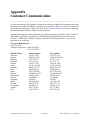
Customer Communication
National Instruments wants to receive your comments on our products and manuals. We are
interested in the applications you develop with our products, and we want to help if you have
problems with them. To make it easy for you to contact us, this manual contains comment and
configuration forms for you to complete. These forms are in the appendix at the end of this manual.
© National Instruments Corporation
vii
BNC-208X Series User Manual
Contents
Chapter 1
Introduction .........................................................................................................................1-1
What Your Kit Should Contain......................................................................................1-3
Optional Equipment .......................................................................................................1-3
Signal Conditioning Accessories ...................................................................................1-4
Software Support............................................................................................................1-5
Unpacking ......................................................................................................................1-5
Chapter 2
BNC-2080 Board ................................................................................................................2-1
Power Connections ........................................................................................................2-3
Analog Input...................................................................................................................2-3
Shield Ground ................................................................................................................2-5
Fuse and Power LED .....................................................................................................2-6
Digital and Timing Signals ............................................................................................2-6
Specifications.................................................................................................................2-6
Analog Input ......................................................................................................2-6
Power Requirements ..........................................................................................2-7
Physical ..............................................................................................................2-7
Operating Environment......................................................................................2-7
Storage Environment..........................................................................................2-7
Board-to-Board Cabling.................................................................................................2-7
Mounting........................................................................................................................2-9
Application Notes ..........................................................................................................2-9
Soldering and Desoldering on the BNC-2080 Board.........................................2-9
Channel Configurations .....................................................................................2-9
MIO-16 Analog Input ............................................................................2-9
Connecting Nonreferenced (or Floating) Signal Sources ..................................2-13
Differential Inputs..................................................................................2-13
Single-Ended Inputs...............................................................................2-14
Connecting Ground-Referenced Signal Sources................................................2-15
Differential Inputs..................................................................................2-15
Single-Ended Inputs...............................................................................2-15
Building Lowpass Filters ...................................................................................2-15
Building Highpass Filters...................................................................................2-17
Building Attenuators (Voltage Dividers)...........................................................2-20
PC-LPM-16............................................................................................2-22
MIO-16 Analog Output..........................................................................2-23
Chapter 3
BNC-2081 Board ................................................................................................................. 3-1
Analog Input ..................................................................................................................3-2
Shield Ground ................................................................................................................3-4
Fuse and Power LED .....................................................................................................3-5
Digital and Timing Signals ............................................................................................3-5
© National Instruments Corporation
ix
BNC-208X Series User Manual
Contents
Specifications.................................................................................................................3-5
Analog Input ......................................................................................................3-5
Power Requirements ..........................................................................................3-5
Physical ..............................................................................................................3-6
Operating Environment......................................................................................3-6
Storage Environment..........................................................................................3-6
Board-to-Board Cabling.................................................................................................3-6
Mounting........................................................................................................................3-8
Application Notes ..........................................................................................................3-8
Soldering and Desoldering on the BNC-2081 Board.........................................3-8
Connecting Nonreferenced (or Floating) Signal Sources ..................................3-8
Connecting Ground-Referenced Signal Sources................................................3-8
Building Lowpass Filters ...................................................................................3-9
Building Highpass Filters...................................................................................3-11
Building Attenuators (Voltage Dividers)...........................................................3-12
Lab Board Analog Output..............................................................................................3-14
Chapter 4
Installation and Connections ..........................................................................................4-1
Hardware Installation.....................................................................................................4-1
Hardware Installation for the BNC-2080 and the BNC-2081............................4-1
Installing the SC-205X Series Cable Adapter Boards .......................................4-2
Installing the SC-207X General-Purpose Termination Breadboards.................4-2
Rack Mounting...................................................................................................4-2
External Power Connection (If Necessary)........................................................4-5
BNC-208X Series Board Connection ................................................................4-6
Signal Connections ........................................................................................................4-7
Ribbon-Cable Connectors..................................................................................4-7
Rack-Mount Chassis Cover Attachment............................................................4-7
Appendix
Customer Communication...............................................................................................A-1
Index ..................................................................................................................................Index-1
Figures
Figure 1-1.
Figure 1-2.
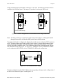
BNC-2080 Board Directly Connected to an MIO-16 Board............................1-2
BNC-208X, SC-207X, SC-206X, and SC-205X Series Boards
Connected to an MIO-16 Board .......................................................................1-2
Figure
Figure
Figure
Figure
Figure
BNC-2080 Analog Breakout Board..................................................................2-1
BNC-2080 Board Parts Locator Diagram.........................................................2-2
Onboard Equivalent Circuit for DIFF Mode ....................................................2-4
W2 Jumper Settings..........................................................................................2-5
Direct Connection between an MIO-16 Board and the BNC-2080 Board.......2-8
2-1.
2-2.
2-3.
2-4.
2-5.
BNC-208X Series User Manual
x
© National Instruments Corporation
Contents
Figure 2-6.
Figure 2-7.
Figure 2-8.
Figure 2-9.
Figure 2-10.
Figure 2-11.
Figure
Figure
Figure
Figure
Figure
Figure
Figure
Figure
2-12.
2-13.
2-14.
2-15.
2-16.
2-17.
2-18.
2-19.
Figure
Figure
Figure
Figure
Figure
Figure
3-1.
3-2.
3-3.
3-4.
3-5.
3-6.
Figure
Figure
Figure
Figure
Figure
Figure
Figure
3-7.
3-8.
3-9.
3-10.
3-11.
3-12.
3-13.
Figure 4-1.
Figure 4-2.
Figure 4-3.
Figure 4-4.
Figure 4-5.
Connection between an MIO-16 Board, the BNC-2080 Board, and
the SC-2070/72 Board or the MIO-16, and the BNC-2080 and
SC-206X Series Boards via the SC-2050 Board ..............................................2-8
Switch Configurations for Differential Mode or Single-Ended Mode .............2-10
W1 Ground Reference Jumper .........................................................................2-10
BNC-2080 Switch Configurations for an MIO-16 Configured in
DIFF Mode (Factory Default Setting) ..............................................................2-11
BNC-2080 Switch Configurations for an MIO-16 Configured in
RSE and NRSE Modes .....................................................................................2-12
Bias Return Resistor for DC-Coupled Floating Source on Channel 1
in DIFF Mode ...................................................................................................2-14
Normalized Frequency Response of Lowpass Filter........................................2-16
Lowpass Filter on Differential Channel 1 ........................................................2-17
Normalized Frequency Response of Highpass Filter .......................................2-18
Highpass Filter on Differential Channel 1........................................................2-19
Attenuator for Use with Differential Inputs......................................................2-21
Switch Configurations for SE Mode (PC-LPM-16) .........................................2-22
Ground Reference Jumper Position for Use with the PC-LPM-16 ..................2-23
Analog Output Schematic for DACs, DAC0 OUT Shown .............................2-23
BNC-2081 Analog Breakout Board..................................................................3-1
BNC-2081 Board Parts Locator Diagram.........................................................3-2
Onboard Equivalent Circuit..............................................................................3-3
W1 Jumper Settings..........................................................................................3-4
Direct Connection between a Lab Board and the BNC-2081 Board................3-7
Connection between a Lab Board, the BNC-2081, and the SC-2071 Board,
or the Connection between a Lab Board, the BNC-2081 and the SC-206X
Series Board, via the SC-2053 Board...............................................................3-7
Normalized Frequency Response of Lowpass Filter........................................3-9
Lowpass Filter on Channel 1 ............................................................................3-10
Normalized Frequency Response of Highpass Filter .......................................3-11
Highpass Filter on Channel 1 ...........................................................................3-12
Attenuator for Use with BNC-2081 Board Inputs............................................3-13
DAC0 OUT Schematic.....................................................................................3-14
Analog Output Schematic for DACs, DAC0 OUT Shown .............................3-14
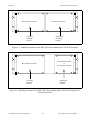
Mounting Locations for the BNC-208X Series Board and SC-207X
Series Board......................................................................................................4-3
Mounting Locations for the BNC-208X Series Board and SC-205X
Series Board or SC-206X Series Board............................................................4-3
Attaching a Mountable Board to the Chassis ...................................................4-4
Double-Height Mounting..................................................................................4-5
Connections between Data Acquisition Boards and BNC-208X
Series Boards and between SC-205X Series Boards and BNC-2080
and BNC-2081 Boards......................................................................................4-6
© National Instruments Corporation
xi
BNC-208X Series User Manual
Contents
Tables
Table 1-1.
Data Acquisition Boards for Use with BNC-208X Series Boards ...................1-1
Table 2-1
Table 2-2.
Table 2-3.
Switch S5 Settings for National Instruments Data Acquisition Boards ...........2-3
DIFF Mode Channel Component Positions......................................................2-5
Data Acquisition Boards Used with the BNC-2080 Board ..............................2-7
Table 3-1.
Table 3-2.
Component Positions in Each Channel.............................................................3-4
Data Acquisition Boards Used with the BNC-2081 Board ..............................3-6
BNC-208X Series User Manual
xii
© National Instruments Corporation
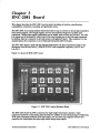
Chapter 1
Introduction
This chapter describes the BNC-208X Series boards; lists the contents of your BNC-2080 and BNC2081 kits; describes the optional equipment, signal conditioning accessories, and software support; and
explains how to unpack your BNC-208X Series board.
The BNC-2080 and BNC-2081 boards are two analog breakout boards with signal-labeled BNC
connectors and analog signal conditioning areas. The BNC-2080 and BNC-2081 breakout boards
simplify the connection of analog signals, some digital signals, and two user-defined connections to the
data acquisition board in laboratory, test, and production environments. The BNC-2080 can be
configured to use 8 differential or 16 single-ended analog input channels available on the board. The
boards have silkscreened component locations for resistors, and capacitors for building single-pole
highpass and lowpass filters, and voltage dividers.
Table 1-1 lists the specific data acquisition boards that can currently be used with the BNC-208X Series
boards.
Table 1-1. Data Acquisition Boards for Use with BNC-208X Series Boards
BNC-2080
NB Series
(Macintosh
NuBus)
MC Series
(IBM PS/2)
PC and AT
Series
(PC/XT/AT)
NB-MIO-16
NB-MIO-16X
MC-MIO-16
AT-MIO-16
AT-MIO-16D
AT-MIO-16F-5
AT-MIO-16X
PC-LPM-16
BNC-2081
Note:
Lab Series
(PC/XT/AT and
Macintosh
NuBus)
Lab-LC
Lab-NB
Lab-PC
Lab-PC+
When a board is referred to as an MIO-16 board, the reference applies to the AT-MIO-16,
AT-MIO-16D, AT-MIO-16F-5, AT-MIO-16X, MC-MIO-16, NB-MIO-16, NB-MIO-16X,
and PC-LPM-16 boards listed in Table 1-1. Similarly, when a board is referred to simply as a
Lab board, the reference applies to the Lab-LC, Lab-NB, Lab-PC+ and Lab-PC boards listed in
Table 1-1.
All analog signals from the data acquisition board are made available at BNC connectors. Each of the
BNC-208X Series boards is connected directly to the data acquisition board (NB, MC, Lab, PC, or
AT Series) by a 50-pin ribbon cable. The AT-MIO-16D requires an NB5 cable. The Lab-LC requires
an NB10 cable. If any SC-206X Series digital signal conditioning boards are also being used with the
same data acquisition board for conditioning of the digital I/O signals, then an SC-205X Series cable
adapter board is required.
© National Instruments Corporation
1-1
BNC-208X Series User Manual
Chapter 1
Introduction
What Your Kit Should Contain
There are three kit versions for each of the BNC-2080 and the BNC-2081 boards–one kit contains a 0.5
m cable, one kit contains a 1.0 m cable, and one kit contains no cable, listed as follows.
Kit Name
Kit Part
Number
Kit Component
Board Part
Number
BNC-2080 kit with 0.5 m
cable
776579-05
BNC-2080 board
50-conductor 0.5 m NB1 cable
181630-01
180524-05
BNC-2080 kit with 1.0 m
cable
776579-10
BNC-2080 board
50-conductor 1.0 m NB1 cable
181630-01
180524-10
BNC-2080 without cable
BNC-2081 kit with 0.5 m
cable
776579-90
776599-05
BNC-2080 board
BNC-2081 board
50-conductor 0.5 m NB1 cable
181630-01
181635-01
180524-05
BNC-2081 kit with 1.0 m
cable
776599-10
BNC-2081 board
50-conductor 1.0 m NB1 cable
181635-01
180524-10
BNC-2081 without cable
776599-90
BNC-2081 board
181635-01
You can identify which version of the BNC-208X Series kit you have by looking up the part number in
the preceding table.
In addition to the board, each version of the BNC-208X Series kit contains the following component.
Kit Component
BNC-208X Series User Manual
Part Number
320407-01
If your kit is missing any of the components or if you received the wrong version, contact National
Instruments.
Optional Equipment
Equipment
Type NB5 cable (for the AT-MIO-16D)
0.5 m
1.0 m
Rack-mount chassis kit with acrylic plastic cover
Single height
Double height
Rack-mount chassis kit with metal wraparound cover
Single height
Double height
© National Instruments Corporation
1-3
Part Number
181304-05
181305-05
180636-01
180636-02
181080-01
181080-02
BNC-208X Series User Manual
Introduction
Chapter 1
Signal Conditioning Accessories
Accessory
Part Number
SSR Series eight-channel backplane
with 0.4 m cable for SC-2050 Series
776290-18
SC-2070 and 50-conductor cable
0.5 m cable
1.0 m cable
776358-00
776358-10
SC-2071 and 50-conductor cable
0.5 m cable
1.0 m cable
776358-01
776358-11
SC-2072 and 50-conductor cable
0.5 m cable
1.0 m cable
776358-02
776358-12
SC-2072D and 50-conductor cable
0.5 m cable
1.0 m cable
776358-102
776358-112
SC-2060 and 26-conductor cable
0.2 m cable
0.4 m cable
776336-00
776336-10
SC-2061 and 26-conductor cable
0.2 m cable
0.4 m cable
776336-01
776336-11
SC-2062 and 26-conductor cable
0.2 m cable
0.4 m cable
776336-02
776336-12
SC-2050 and 50-conductor cable
0.5 m cable
1.0 m cable
776335-00
776335-10
SC-2051 and 50-conductor cable
0.5 m cable
1.0 m cable
776335-01
776335-11
SC-2052 and 50-conductor cable
0.5 m cable
1.0 m cable
776335-02
776335-12
SC-2053 and 50-conductor cable
0.5 m cable
1.0 m cable
776335-03
776335-13
BNC-208X Series User Manual
1-4
© National Instruments Corporation
Chapter 1
Introduction
Software Support
The BNC-208X Series boards require no additional software support beyond that provided for the data
acquisition board in use.
Unpacking
Your BNC-208X Series board is shipped in an antistatic package to prevent electrostatic damage to the
board. Several components on the board can be damaged by electrostatic discharge. To avoid such
damage in handling the board, take the following precautions:
•
Touch the antistatic package to a metal part of your computer chassis before removing the board
from the package.
•
Remove the board from the package and inspect the board for loose components or any other sign of
damage. Notify National Instruments if the board appears damaged in any way. Do not install a
damaged board into your computer.
© National Instruments Corporation
1-5
BNC-208X Series User Manual
BNC-2080 Board
Chapter 2
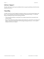
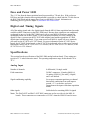
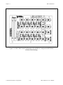
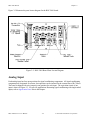
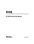
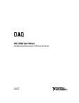
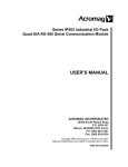
Figure 2-2 illustrates the parts locator diagram for the BNC-2080 board.
Figure 2-2. BNC-2080 Board Parts Locator Diagram
BNC-208X Series User Manual
2-2
© National Instruments Corporation
Chapter 2
BNC-2080 Board
Power Connections
Because the BNC-2080 board is an analog breakout board for both the MIO-16 and PC-LPM-16
boards, it has a flexible power connection scheme.
Switch S5 is responsible for selecting the power inputs from the I/O cable. Switch S5 is a threeposition switch that configures the BNC-2080 to connect to pins 33 (DGND) and 34 (+5 V) in
position A, to no I/O pins in position B, and to pins 49 (+5 V) and 50 (DGND) in position C.
Table 2-1 shows the setting to be used with each of the National Instruments data acquisition
boards.
Table 2-1. Switch S5 Settings for National Instruments Data Acquisition Boards
Board
S5 Setting
AT-MIO-16
AT-MIO-16D
AT-MIO-16F-5
AT-MIO-16X
MC-MIO-16
NB-MIO-16
NB-MIO-16X
PC-LPM-16
A
A
A
A
A
A
A
C
Warning: If the data acquisition board does not use pins 33/34 or pins 49/50 for power
connections, set switch S5 to position B. Failure to set switch S5 to position B under
these conditions could result in damage to your external power supply, the
BNC-2080, the expansion board connected to the BNC-2080, and/or your computer.
National Instruments is not liable for damages resulting from such connections.
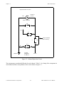
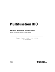
Analog Input
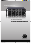
Each differential analog input has seven open positions for signal conditioning components. Six of
these positions are designated as resistors, and one is designated as a capacitor. The board is
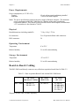
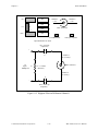
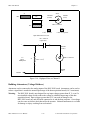
shipped with jumpers in two positions for each input. The equivalent circuit of one input is shown
in Figure 2-3. The board can be used when the MIO-16 board is configured for both 16 singleended inputs and 8 differential inputs. For specific applications illustrating signal conditioning
with both single-ended and differential inputs, refer to the section titled Application Notes later in
this chapter.
© National Instruments Corporation
2-3
BNC-208X Series User Manual
BNC-2080 Board
Chapter 2
Input Schematic for ACH1 (DIFF mode)
S2
AISENSE
DIFF
SE
AIGND
3
2
Channel 9
(Center)
2
NRSE
3
RSE
1
COMMON
Case
1
W1
Channel 1
(Center)
Case
BNC Connector
BNC Connector
+5 V
+5 V
R21
R4
C
A
Jumpers Installed
Here at Factory
R15
R11
D
B
AIGND
F
R20
R3
E
AIGND
C2
G
ACH 9
(-in)
To Input
Multiplexer
on MIO-16
ACH 1
(+in)
Figure 2-3. Onboard Equivalent Circuit for DIFF Mode
The components are numbered differently for each channel. Table 2-2 lists the components in each
channel and their correspondence to the circuit shown in Figure 2-3.
BNC-208X Series User Manual
2-4
© National Instruments Corporation
Chapter 2
BNC-2080 Board
Table 2-2. DIFF Mode Channel Component Positions
Channel
(Position in Figure 2-3)
Differential
Single-Channel
0
(0, 8)
1
A
B
C
D
E
F
G
R2
R10
R19
R14
R1
R18
C1
(1, 9)
R4
R11
R21
R15
R3
R20
C2
2
(2, 10)
R6
R12
R23
R16
R5
R22
C3
3
(3, 11)
R8
R13
R25
R17
R7
R24
C4
4
(4, 12)
R28
R35
R45
R39
R27
R44
C9
5
(5, 13)
R30
R36
R47
R40
R29
R46
C10
6
(6, 14)
R32
R37
R49
R41
R31
R48
C11
7
(7, 15)
R34
R38
R51
R42
R33
R50
C12
When the board is shipped, jumpers are inserted in the E and F positions of the input network, as
in Figure 2-3. These jumpers can be easily removed to build analog input signal conditioning
circuits. Several applications showing the use of these open component positions are discussed in
the section titled Application Notes later in this chapter.
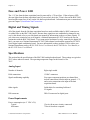
Shield Ground
Jumper W2 is used to connect digital ground (DGND) to a grounded metal case. This option is
useful only if the BNC-2080 board is on metal standoffs and is mounted in a grounded metal case.
Shield grounding can be selected to reduce noise.
Figure 2-4 details the jumper settings for W2.
W2
•
••
•
••
W2
Shield Ground Selected
Shield Ground Not Selected
Figure 2-4. W2 Jumper Settings
© National Instruments Corporation
2-5
BNC-208X Series User Manual
BNC-2080 Board
Chapter 2
Fuse and Power LED
The +5-V line from the data acquisition board is protected by a 750-mA fuse. If the red power
LED does not light when the data acquisition board is powered on, check both the 750-mA fuse on
the BNC-2080 board and the output fuse (if any) on the MIO-16 board. Information on
connecting power is given in Chapter 4, Installation and Connections.
Digital and Timing Signals
All of the analog signals and a few digital signals from the MIO-16 data acquisition board are made
available at BNC connectors on the BNC-2080 board. Because these signals are not conditioned
or changed in any way by the BNC-2080 board, refer to your MIO-16 board user manual for
information on the use of these signals. If you want optical isolation of or relay control by the
digital I/O lines, you must use the SC-2050 cable adapter board and the appropriate SC-2060
digital signal conditioning board. If you want access to all MIO-16 signals via screw terminals,
you must use the SC-2070 or SC-2072 board. For more information on the SC-205X Series
boards, the SC-206X Series boards, or the SC-207X Series boards, refer to either your National
Instruments catalog, the SC-205X Series User Manual, the SC-206X Series User Manual, or the
SC-207X Series User Manual.
Specifications
This section lists the specifications of the BNC-2080 analog breakout board. These ratings are
typical at 25° C unless otherwise stated. The operating temperature range for this board is 0° to
70° C.
Analog Input
Number of channels
8 differential, 16 single-ended
Field connections
24 BNC connectors; 18 analog (MIO-16)
16 analog (LPM-16), [See note], 4 digital,
and 2 user-defined
Signal conditioning capability
Seven open component positions per channel
that include connections from each input to
ground, +5 V, each other, and series
connections to the inputs of the data acquisition
boards
Other signals
Solder holes for remaining MIO-16 signals
Note: The DAC0 OUT and DAC1 OUT BNC connectors are for use with only the MIO-16
boards. These connectors are connected to ±12 VDC when the LPM-16 board is in use.
BNC-208X Series User Manual
2-6
© National Instruments Corporation
Chapter 2
BNC-2080 Board
Power Requirements
Power consumption (at +5 VDC ±5%)
Typical
Maximum
12 mA with no signal conditioning installed
750 mA from host computer
Note: The power specifications pertain to the power supply of the host computer. The maximum
power consumption of the BNC-2080 board is a function of the signal conditioning
components installed. If the board is being powered from the host computer, the maximum
+5-V current draw is fuse-limited to 750 mA.
Physical
Board dimensions (including standoffs)
7.9 by 4.9 by 1.725 in.
I/O connectors
Two 50-pin male ribbon-cable connectors
BNC connectors
24
Operating Environment
Temperature
0° to 70° C
Relative humidity
5% to 90% noncondensing
Storage Environment
Temperature
-55° to 125° C
Relative humidity
5% to 90% noncondensing
Board-to-Board Cabling
The BNC-2080 board directly connects to any of the data acquisition boards listed in Table 2-3.
Table 2-3. Data Acquisition Boards Used with the BNC-2080 Board
BNC-2080
NB Series
(Macintosh NuBus)
MC Series
(IBM PS/2)
NB-MIO-16
NB-MIO-16X
MC-MIO-16
AT Series
(PC AT)
AT-MIO-16
AT-MIO-16D*
AT-MIO-16F-5
AT-MIO-16X
PC-LPM-16
*Requires an NB5 cable, available separately.
© National Instruments Corporation
2-7
BNC-208X Series User Manual
BNC-2080 Board
Chapter 2
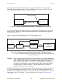
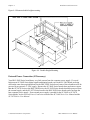
The data acquisition boards listed in Table 2-3, except for the AT-MIO-16D, connect to the
BNC-2080 board as shown in Figure 2-5. The AT-MIO-16D connects to the BNC-2080 via a
100-conductor type NB5 ribbon cable, available separately.
50-Pin I/O Connector
MIO-16
BNC-2080
50-Conductor Cable
Figure 2-5. Direct Connection between an MIO-16 Board and the BNC-2080 Board
If any signal conditioning of the digital I/O ports with the National Instruments SC-206X Series
boards is desired, then the SC-2050 cable adapter board must be used with the data acquisition
boards listed in Table 2-2.
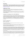
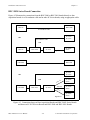
Figure 2-6 shows a connection using the SC-2050 cable adapter board.
50-Conductor
Cable
SC-2070/72
Digital I/O
MIO-16
BNC-2080
SC-2050
50-Conductor
Cable
26-Conductor
Cable
SC-206X Series
or
8-Channel SSR
Figure 2-6. Connection between an MIO-16 Board, the BNC-2080 Board, and the
SC-2070/72 Board or the MIO-16, and the BNC-2080 and SC-206X Series Boards
via the SC-2050 Board
Warning: Do not connect the BNC-2080 board to any board other than a National Instruments
MIO-16 data acquisition board, the SC-2070/72 board, or the SC-2050 cable adapter
board. The BNC-2080 board is not compatible with any other data acquisition
boards or cable adapter boards. Attempts to use the BNC-2080 board with products
for which it is not intended can result in damage to the BNC-2080 board, the data
acquisition board, or the host computer. National Instruments is not liable for
damages resulting from these connections.
The BNC-2080 board uses a 50-pin ribbon-cable connector to connect to the 50-pin I/O connector
on either a data acquisition board, the SC-2070/72, or the SC-2050 cable adapter board. The
BNC-2080 has two MIO-16 connectors for connecting to the SC-2070/72 board or the SC-206X
Series board via the SC-2050 board. For more information, see Chapter 4, Installation and
Connections.
BNC-208X Series User Manual
2-8
© National Instruments Corporation
Chapter 2
BNC-2080 Board
Mounting
The BNC-2080 board is equipped with metal standoffs so the board can be placed on a workbench
near the host computer. You can use an optional rack-mount chassis, which can be fitted with a
flat, acrylic plastic cover. When the BNC-2080 board is mounted in the chassis, the board can be
grounded to its metal standoffs, and therefore to the rack. For more information, see Chapter 4,
Installation and Connections.
Application Notes
The open component positions on the BNC-2080 board make adding signal conditioning
components to the analog input signals easier. Several applications are covered in this section,
including filtering and attenuation.
The figures in this section give examples on a specific input channel. If you want to install the
circuit on a different channel, consult Table 2-3 to determine the equivalent component positions
for the other channels.
Soldering and Desoldering on the BNC-2080 Board
The applications discussed here require you to make modifications to the printed circuit board,
usually by removing jumpers and adding components. The BNC-2080 board is shipped with wire
jumpers in the E and F positions (see Table 2-3 and Figure 2-3). Use a low-wattage soldering iron
(20 to 30 W) when soldering to the board. To desolder on the BNC-2080, vacuum-type tools
work best. Use care when desoldering to avoid damaging component pads. Only rosin-core,
electronic-grade solder should be used. Acid-core solder damages the printed circuit board and
components.
Channel Configurations
MIO-16 Analog Input
This section discusses the input configuration of the MIO-16 board and the corresponding
configurations of the BNC-2080.
The analog input channels of an MIO-16 data acquisition board can be configured for one of three
input modes: differential (DIFF) input mode, referenced single-ended (RSE) input mode, or
nonreferenced single-ended (NRSE) input mode.
Although the open component positions are placed to facilitate use with differential inputs, any of
the three modes can be selected. If the MIO-16 board is configured in the RSE mode, all 16 analog
input channels are referenced to AIGND. If the MIO-16 board is configured in the NRSE mode,
resistors should not be inserted into positions B or D of Figure 2-3 for any channel. Doing so can
cause inaccurate readings because of incorrect ground reference. Resistors can be inserted into
these positions in the RSE mode. For information on the input configurations, see your MIO-16
board user manual.
The BNC-2080 board can be configured to work with all three MIO-16 input configurations. The
DIFF mode is configured by flipping the switches next to each pair of BNC connectors to DIFF.
This must be done to all eight switches in order to have eight differential channels. In DIFF mode,
the first eight analog (ACH0 through ACH7) BNC connectors are used. The remaining eight
© National Instruments Corporation
2-9
BNC-208X Series User Manual
BNC-2080 Board
Chapter 2
ACH0
ACH0
ACH8
DIFF
J9
ACH8
DIFF
S2
S2
SE
SE
J3
J3
J9
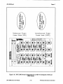
analog (ACH8 through ACH15) BNC connectors are not used. The MIO-16 board must also be
configured for differential input. The jumper W1 position is irrelevant in DIFF mode.
DIFF Mode
(Factory Default Setting)
SE Mode
Figure 2-7. Switch Configurations for Differential Mode or Single-Ended Mode
Note: All of the switches are required to be in the same position; that is, S1 through S4 and S6
through S9 must all be in either the DIFF position or in the SE position.
The single-ended mode is configured by flipping the switches next to each pair of BNC connectors
to SE. This must be done to all eight switches in order to have 16 single-ended channels. In the
single-ended mode, all 16 BNC connectors are in use. In the single-ended mode, all 16 BNC
cases are tied to the COMMON signal. The COMMON signal can be switched between AIGND
and AISENSE through jumper W1. See Figure 2-8. AISENSE is tied to COMMON for NRSE
mode configuration and AIGND is tied to COMMON for RSE mode configuration.
RSE
•
•
•
AISENSE
COMMON
AIGND
•
W1
W1
NRSE
Figure 2-8. W1 Ground Reference Jumper
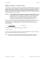
The three configurations of the BNC-2080 board corresponding to the input mode configuration of
the MIO-16 are shown in Figure 2-9 and Figure 2-10.
BNC-208X Series User Manual
2-10
© National Instruments Corporation
Chapter 2
BNC-2080 Board
Figure 2-9. BNC-2080 Switch Configurations for an MIO-16 Configured in DIFF Mode
(Factory Default Setting)
© National Instruments Corporation
2-11
BNC-208X Series User Manual
Chapter 2
BNC-2080 Board
As described in Chapter 2 of your MIO-16 board user manual, the input configuration of the
MIO-16 depends on the type of signal source. There are two types of signal sources:
nonreferenced or floating signals and ground-referenced signals. To measure floating signal
sources, the MIO-16 should be configured for the RSE mode or DIFF mode with bias resistors.
To measure ground-referenced signal sources, the MIO-16 should be configured for the NRSE
mode or DIFF mode. Both types of signal sources and the recommended methods for MIO-16
board connection are discussed as follows.
Connecting Nonreferenced (or Floating) Signal Sources
A floating signal source is a signal source that is not connected in any way to the building ground
system, but has an isolated ground-reference point. If an instrument or device has an isolated
output, that instrument or device falls into the floating signal source category. Some examples of
floating signal sources are outputs for: thermocouples, transformers, battery-powered devices,
optical isolators, and isolation amplifiers. The ground reference of a floating source must be tied to
the ground of the data acquisition board to establish a local or onboard reference for the signal.
Differential Inputs
To provide a return path for the instrumentation amplifier bias currents, floating sources must have
a 10-k1 to 100-k1 resistor to AIGND on one input if DC-coupled, or both inputs if AC-coupled.
For more detailed information on connections to floating signal sources and differential inputs,
refer to the configuration chapter in your MIO-16 board user manual. These bias resistors can be
installed in positions B and D (Table 2-2 and Figure 2-3) of the BNC-2080 board. Figure 2-11
shows both the schematic and the component placement for a single 100-k1 bias return resistor on
the negative input from a floating source connected to Channel 1 (the D position in Table 2-2).
Additional signal conditioning circuitry, such as filters and attenuators, as described in the sections
Building Lowpass Filters, Building Highpass Filters, and Building Attenuators (Voltage Dividers)
later in this chapter, can be built in the open component positions.
© National Instruments Corporation
2-13
BNC-208X Series User Manual
BNC-2080 Board
Chapter 2
R3
E
R4
A
R11
B
Channel 1
(+in)
Channel 9
(-in)
G C2
D
R15
F
R20
R21
BNC Connector
C
100-k1 Resistor
Input Schematic for ACH1
R3
+
Channel 1
(+in {Center})
E
To
Input
Multiplexer
BNC Connector
G (C2)
AIGND
R15 = 100 k1
D
Channel 9
(-in {Case})
F
R20
Figure 2-11. Bias Return Resistor for DC-Coupled Floating Source on Channel 1 in
DIFF Mode
Single-Ended Inputs
When measuring floating signal sources, the MIO-16 board should be configured to supply a
ground reference. Therefore, the MIO-16 should be configured for RSE mode. In this
configuration, the negative input of the MIO-16 instrumentation amplifier is tied to the analog
ground. Therefore, the BNC-2080 board should be used in its factory configuration. In the
factory configuration, jumpers are in the two series positions, E and F (see Table 2-2). In this
configuration, all of the signal grounds should be tied to AIGND. Signal conditioning circuitry
such as filters and attenuators, as described in the sections titled Building Lowpass Filters,
Building Highpass Filters, and Building Attenuators (Voltage Dividers) later in this chapter, can be
built in the open component positions.
BNC-208X Series User Manual
2-14
© National Instruments Corporation
Chapter 2
BNC-2080 Board
Connecting Ground-Referenced Signal Sources
A grounded signal source is connected in some way to the building system ground; therefore, the
signal source is already connected to a common ground point with respect to the data acquisition
board (assuming the host computer is plugged into the same power system). The nonisolated
outputs of instruments and devices that plug into the building power system fall into this category.
Differential Inputs
If the MIO-16 data acquisition board is configured for differential inputs, ground-referenced signal
sources connected to the BNC-2080 board need no special components added to the BNC-2080
board. The inputs of the BNC-2080 board can be left in the factory-original condition, that is,
with only jumpers in the two series positions, E and F (see Table 2-3). Signal conditioning
circuitry, such as filters and attenuators, as described in the sections titled Building Lowpass
Filters, Building Highpass Filters, and Building Attenuators (Voltage Dividers) later in this
chapter, can be built in the open component positions.
Single-Ended Inputs
When measuring ground-referenced signals, the external signal supplies its own reference ground
point and the MIO-16 should not supply one. Therefore, the MIO-16 board should be configured
for the NRSE mode. In this configuration, all of the signal grounds should be tied to AISENSE,
which connects to the negative input of the instrumentation amplifier on the MIO-16 board. The
inputs of the BNC-2080 board can be left in the factory-original condition, that is, with jumpers in
the series position (E or F, depending on the channel). The open positions that connect the input to
AIGND, B and D (see Table 2-2 and Figure 2-3), should not be used in this configuration.
Referencing the signal to AIGND can cause inaccurate measurements resulting from an incorrect
ground reference.
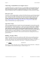
Building Lowpass Filters
Simple, R-C lowpass filters are easily installed in the BNC-2080 board on any differential input
channel. The filters are useful for accurate measurement and noise rejection. By substituting
resistance and capacitance values into the following formula (hereafter referred to as Formula 2-1),
you can calculate a simple, one-pole R-C filter to have a -3-dB point cutoff frequency (fc):
1
fc = (2/RC)
(Formula 2-1)
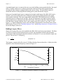
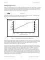
The frequency response rolls off at a rate of -20 dB per decade of increase thereafter. A Bode plot
of the amplitude versus normalized frequency is shown in Figure 2-12.
© National Instruments Corporation
2-15
BNC-208X Series User Manual
BNC-2080 Board
Chapter 2
dB
Amplitude
1
0
0.1
-20
0.01
-40
0.001
-60
0.0001
-80
|
0.1
|
1
(fc )
|
10
|
100
|
1,000
|
10,000
Normalized Frequency
Figure 2-12. Normalized Frequency Response of Lowpass Filter
When measuring low-frequency signals (about 4 Hz), if you have 400-Hz noise on your inputs,
you can add a lowpass filter with a cutoff frequency of 4 Hz. The 400-Hz noise then attenuates by
40 dB. Notice that your 4-Hz signal also attenuates, but by only 3 dB. Do not neglect any
potential attenuation of signals of interest by this low-order filter.
You must also choose the filter component values. The resistance or the capacitance can be
selected arbitrarily; one value determines the other. Picking the capacitor first and letting its value
determine the resistance required is preferable because more standard resistor values are available.
If a capacitance of 1 µF is available, the resistance is (by substitution into Formula 2-1) 39,789 1,
or about 39.8 k1. This resistance must be divided by two to get the resistor value on each input of
a differential channel. Therefore, in this example, each input has a 19.89-k1 resistor (or the
closest standard value) in its series positions, E and F. The closest standard 5% tolerance resistors
are 20 k1. The closest standard 0.5% resistors are 19.8 k1. National Instruments recommends
using 1% or better tolerance resistors in this application because differences between the resistor
values degrade the common-mode rejection ratio (CMRR). Figure 2-13 shows both the schematic
and the component placement for a 4-Hz lowpass filter placed on differential input Channel 1. If
the input signal source is floating, a bias return resistor must be placed in the D position (R15 in
this case).
The BNC-2080 board open component locations do not facilitate R-C lowpass filters with the
MIO-16 board configured for single-ended inputs. Therefore, if the MIO-16 board is configured
for single-ended inputs, lowpass filters must be built on the custom breadboard area.
BNC-208X Series User Manual
2-16
© National Instruments Corporation
Chapter 2
BNC-2080 Board
A Channel 1
(+in)
R4
R3
E
C2
R11
B
R15
D
R21
C
Channel 9
(-in)
G
F
R20
BNC Connector
19.8-k1 Resistor
1-µF Capacitor
Input Schematic for ACH1
R3 = 19.8 k1
+
E
To
G
Input
Multiplexer
Channel 1
(+in {Center})
BNC Connector
C2 = 1 µF
Channel 9
(-in {Case})
F
R20 = 19.8 k1
Figure 2-13. Lowpass Filter on Differential Channel 1
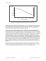
Building Highpass Filters
Simple, R-C highpass filters are easily installed in the BNC-2080 board on any differential input
channel. The filters are useful for accurate high-frequency measurement and low-frequency noise
rejection. By substituting resistance and capacitance values into the following formula, hereafter
referred to as Formula 2-2, you can calculate a simple, one-pole R-C filter to have a -3-dB point fc:
1
fc = (2/RC)
(Formula 2-2)
The frequency response rolls off at a rate of -20 dB per decade decrease thereafter. A Bode plot of
the amplitude versus normalized frequency is shown in Figure 2-14.
© National Instruments Corporation
2-17
BNC-208X Series User Manual
BNC-2080 Board
Chapter 2
dB
Amplitude
0
1
0.1
-20
0.01
-40
0.001
-60
0.0001
-80
|
0.0001
|
0.001
|
0.01
|
0.1
Normalized
|
1
Frequency
|
10
(f c)
Figure 2-14. Normalized Frequency Response of Highpass Filter
When measuring high-frequency signals (about 50 kHz), if you have 50-Hz noise on your inputs,
you can add a highpass filter with a cutoff frequency of 50 kHz. The 50-Hz noise then attenuates
by 60 dB. Notice that your 50-kHz signal also attenuates, but by only 3 dB. Do not neglect any
potential attenuation of signals of interest if you add a low-order filter.
You must also choose the filter component values. The resistance or the capacitance can be
selected arbitrarily; one value determines the other. Picking the capacitor first and letting its value
determine the resistance required is preferable because more standard resistor values are available.
The filter circuit has one series capacitor on each input of the differential channel. Because the two
capacitors are in series, the capacitance value that must be substituted into Formula 2-2 is the series
capacitance of the two capacitors in series. For two capacitors in series, the net capacitance is the
reciprocal of the sum of the reciprocals of the two capacitances. For example, two 0.001-µF
capacitors in series have a net capacitance of 0.0005 µF. The two capacitors should be the same
value, or the CMRR is degraded. If capacitors of 0.001 µF are available, the resistance is (by
substitution into Formula 2-2) 6,366 1, or about 6.4 k1. Therefore, in this example, the input
channel has a 6.37-k1 resistor (or the closest standard value) in its capacitor position, G. The
closest standard 5% tolerance resistors are 6.2 k1. The closest standard 1% resistors are 6.34 k1.
Figure 2-15 shows both the schematic and the component placement for a 50-kHz highpass filter
placed on differential input Channel 1. If the input signal source is floating, a bias return resistor
must be placed in the D position (R15 in this case).
Note: Highpass filters generally exhibit poorer common-mode rejection characteristics than
lowpass filters because capacitors are in the series input paths. Capacitors have poorer
tolerances than resistors, and matching of the input impedances is crucial for good
common-mode rejection.
The BNC-2080 board open component locations do not facilitate R-C highpass filters with the
MIO-16 board configured for single-ended inputs. Therefore, if the MIO-16 board is configured
for single-ended inputs, highpass filters must be built on the custom breadboard area.
Note: Due to space constraints, when a resistor is inserted in position G (capacitor position) it
must be inserted vertically before bending the other lead to the board.
BNC-208X Series User Manual
2-18
© National Instruments Corporation
Chapter 2
BNC-2080 Board
A Channel 1
(+in)
R4
R3
Channel 9
(-in)
E
C2
R11
B
R15
D
R21
C
G
F
R20
BNC Connector
6.34-k1 Resistor
0.001-µF Capacitor
Input Schematic for ACH1
R3 = 0.001 µF
(Capacitor)
+
Channel 1
(+in {Center})
E
To
G
Input
Multiplexer
BNC Connector
C2 = 6.34 k1
(Resistor)
Channel 9
(-in {Case})
F
R20 = 0.001 µF
(Capacitor)
Figure 2-15. Highpass Filter on Differential Channel 1
© National Instruments Corporation
2-19
BNC-208X Series User Manual
BNC-2080 Board
Chapter 2
Building Attenuators (Voltage Dividers)
Attenuators can be connected to the analog inputs of the BNC-2080 board when the inputs from its
data acquisition board are in DIFF mode. The BNC-2080 board open component positions do not
facilitate voltage dividers with the MIO-16 board configured for single-ended inputs. Therefore, if
the MIO-16 board is configured for single-ended inputs, attenuators must be built on a separate
breadboard. Attenuators can be used to reduce a signal that is outside the normal input range of the
data acquisition board (±10 V maximum).
Warning:
The BNC-2080 board is not designed for any input voltages greater than 42 V, even
if a user-installed voltage divider reduces the voltage to within the input range of the
data acquisition board. Input voltages greater than 42 V can result in damage to the
BNC-2080 board, any and all boards connected to it, and the host computer.
Overvoltage can also cause an electric shock hazard for the operator. National
Instruments is not liable for damage or injury resulting from such misuse.
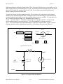
A three-resistor circuit for attenuating voltages at the differential inputs of the BNC-2080 board is
shown in Figure 2-16. The figure also shows the placement of the resistors on the open
component positions for differential Channel 1. The gain G of this attenuator is given by the
following formula:
RG
G = (R + R + R )
E
F
G
(Formula 2-3)
Therefore, the input to the MIO-16 board (VMIO) is as follows:
VMIO = VSC * G
where VSC is the voltage applied to the BNC connectors of the BNC-2080. The accuracy of this
gain equation depends on the tolerances of the resistors used.
Note:
Due to space constraints, when a resistor is to be inserted in position G (capacitor
position) it must be inserted vertically before bending the other lead to the board.
BNC-208X Series User Manual
2-20
© National Instruments Corporation
Chapter 2
BNC-2080 Board
R3
R4
A
R11
C
R15
D
R21
B
E
Channel 1
(+in)
Channel 9
(-in)
G
C2
F
BNC Connector
10-k1 Resistor
R20
Input Schematic for ACH1
R3 = 10 k1
+
E
To
Input
Multiplexer
G
Channel 1
(+in {Center})
BNC Connector
C2 = 10 k1
(Resistor)
Channel 9
(-in {Case})
F
R20 = 10 k1
Figure 2-16. Attenuator for Use with Differential Inputs
© National Instruments Corporation
2-21
BNC-208X Series User Manual
BNC-2080 Board
Chapter 2
Example:
Using the values in Figure 2-13,
10 k1
1
G = (10 k1 + 10 k1 + 10 k1) =
3
Therefore,
VMIO =
1
3
VSC
When the MIO-16 is configured for ±10-V inputs, the board can acquire ±30-V signals with this
attenuator circuit.
If the use of thermocouples is required in your applications, using National Instruments SC-2070
board is better suited for the task. The SC-2070 board is equipped with an onboard temperature
sensor for use with thermocouple cold-junction compensation.
PC-LPM-16
J9
ACH8
DIFF
S2
SE
J3
ACH0
The analog input section of an PC-LPM-16 data acquisition board consists of 16 ground-referenced
single-ended channels; therefore, the only valid configuration for the BNC-2080 is also RSE mode.
In this mode, all 16 analog input BNC connectors are used. Switches S1 through S4 and S6
through S9 must be in the SE position, and jumper W1 should be in the AIGND-COMMON
position, as shown in Figure 2-17 and Figure 2-18, respectively.
Single-Ended Mode
Figure 2-17. Switch Configurations for SE Mode (PC-LPM-16)
Note: All the switches are required to be in the same position; that is, S1 through S4 and S6
through S9 must all be in the SE position for use with the PC-LPM-16.
BNC-208X Series User Manual
2-22
© National Instruments Corporation
Chapter 2
BNC-2080 Board
W1
•
•
AISENSE
COMMON
AIGND
RSE
Figure 2-18. Ground Reference Jumper Position for Use with the PC-LPM-16
The application information given for MIO-16 in the RSE input mode also applies to the
PC-LPM-16.
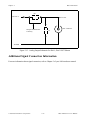
MIO-16 Analog Output
Analog output BNC connectors each have two open component positions for optional signal
conditioning components. One of these is designated as a resistor and the other as a capacitor.
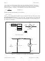
The equivalent circuit for DAC0 OUT is shown in Figure 2-19. DAC1 OUT circuitry is identical
to that of DAC0 OUT.
When the board is shipped, 0-1 jumpers are inserted into the R9 position. These can be easily
removed to build passive analog output signal conditioning circuits such as voltage dividers and
lowpass filters.
R9
DAC0 OUT
DAC0 OUT
BNC Connector
Jumpers Installed Here
at Factory
C5
AOGND
Figure 2-19. Analog Output Schematic for DACs, DAC0 OUT Shown
© National Instruments Corporation
2-23
BNC-208X Series User Manual
BNC-2081 Board
Chapter 3
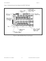
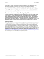
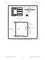
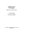
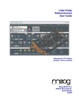
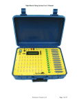
Figure 3-2 illustrates the parts locator diagram for the BNC-2081 board.
Figure 3-2. BNC-2081 Board Parts Locator Diagram
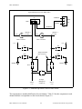
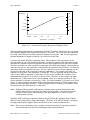
Analog Input
Each analog input has four open positions for signal conditioning components. All signal conditioning
components are designated as resistors, but capacitors can be inserted for the construction of R-C filters.
The board is shipped with wire jumpers in one position for each input. The equivalent circuit of one
input is shown in Figure 3-3. For specific applications illustrating signal conditioning with single-ended
inputs, refer to Application Notes later in this chapter.
BNC-208X Series User Manual
3-2
© National Instruments Corporation
Chapter 3
BNC-2081 Board
Input Schematic for ACH1
Channel 1
(Center)
Case
BNC Connector
R4
A
+5 V
R5
B
C
Jumper Installed
Here at Factory
R6
R14
J4
D
AIGND
To Input
Multiplexer
on MIO-16
ACH 1
Figure 3-3. Onboard Equivalent Circuit
The components are numbered differently for each channel. Table 3-1 is a listing of the components in
each channel and their correspondence to the circuit shown in Figure 3-3.
© National Instruments Corporation
3-3
BNC-208X Series User Manual
BNC-2081 Board
Chapter 3
Table 3-1. Component Positions in Each Channel
Position in Figure 3-3
Channel
A
B
C
D
0
R1
R2
R3
R13
1
R4
R5
R6
R14
2
R7
R8
R9
R15
3
R10
R11
R12
R16
4
R19
R20
R21
R31
5
R22
R23
R24
R32
6
R25
R26
R27
R33
7
R28
R29
R30
R34
When the board is shipped, a jumper is inserted in the C position of the input network. The jumper can
be easily removed to build analog input signal conditioning circuits. A few specific applications showing
the use of these open component positions are discussed in Application Notes later in this chapter.
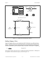
Shield Ground
Jumper W1 is used to connect digital ground (DGND) to a grounded metal case. This option is useful
only if the BNC-2081 board is on metal standoffs and mounted in a grounded metal case. Shield
grounding can be selected to reduce noise.
Figure 3-4 shows the jumper settings for W1.
W2
•
••
•
••
W2
Shield Ground Selected
Shield Ground Not Selected
Figure 3-4. W1 Jumper Settings
BNC-208X Series User Manual
3-4
© National Instruments Corporation
Chapter 3
BNC-2081 Board
Fuse and Power LED
The +5-V line from the data acquisition board is protected by a 750-mA fuse. If the red power LED
does not light when the data acquisition board is powered on, check the 750-mA fuse on the BNC-2081
board and the output fuse (if any) on the Lab data acquisition board. Information on power connection is
given in Chapter 4, Installation and Connections.
Digital and Timing Signals
All of the signals from the Lab data acquisition board are made available either by BNC connectors or
via solder holes on the BNC-2081 board. Because these signals are not conditioned or changed in any
way by this board, refer to your Lab board user manual for information on the use of these signals. If
you want screw terminal access to all signals, a National Instruments SC-2071 board can be used in
conjunction with the BNC-2081 board. If you want optical isolation of or relay control by the digital I/O
lines, you must use a National Instruments SC-2053 cable adapter board and the appropriate SC-206X
Series digital signal conditioning board. For more information on these products, refer to either your
National Instruments catalog, the SC-205X Series User Manual, the SC-206X Series User Manual, or
the SC-207X Series User Manual.
Specifications
This section lists the specifications of the BNC-2081 analog breakout board. These ratings are typical at
25° C unless otherwise stated. The operating temperature range for this board is 0° to
70° C.
Analog Input
Number of channels
Eight single-ended
Field connections
15 BNC connectors
Signal conditioning capability
Four open component positions per channel that
include connections from the input to ground, +5 V,
and a series connection to the input of the data
acquisition board
Other signals
Solder holes for remaining Lab board
I/O signals
DIO connector
DIO-24 connector for digital ports
Power Requirements
Power consumption (at +5 VDC ±5%)
Typical
Maximum
© National Instruments Corporation
12 mA with no user circuitry connected
750 mA from host computer
3-5
BNC-208X Series User Manual
BNC-2081 Board
Chapter 3
Note: The power specifications pertain to the power supply of the host computer. The maximum
power consumption of the BNC-2081 board is a function of the signal conditioning components
installed. If the board is being powered from the host computer, the maximum +5-V current is
fuse-limited to 750 mA.
Physical
Board dimensions (including standoffs)
7.9 by 4.9 by 1.725 in.
I/O connectors
Three 50-pin male ribbon-cable connectors
BNC connectors
15
Operating Environment
Temperature
0° to 70° C
Relative humidity
5% to 90% noncondensing
Storage Environment
Temperature
-55° to 125° C
Relative humidity
5% to 90% noncondensing
Board-to-Board Cabling
The BNC-2081 board directly connects to any of the data acquisition boards listed in Table 3-2.
Table 3-2. Data Acquisition Boards Used with the BNC-2081 Board
Lab Board
(PC/XT and Macintosh NuBus)
BNC-2081 Board
Lab-LC
Lab-NB
Lab-PC
Lab-PC+
The BNC-2081 board directly connects to the Lab-PC, Lab-PC+ and Lab-NB using the 50-pin NB1
cable supplied with the BNC-2081. The Lab-LC board connects to the BNC-2081 using an NB10 cable,
available separately.
BNC-208X Series User Manual
3-6
© National Instruments Corporation
Chapter 3
BNC-2081 Board
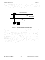
50-Pin I/O Connector
Lab Board
BNC-2081
NB1 (Lab-PC, Lab-PC+, Lab-NB)
or
NB10 (Lab-LC) cable
Figure 3-5. Direct Connection between a Lab Board and the BNC-2081 Board
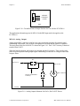
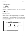
For digital signal conditioning with the National Instruments SC-206X Series boards, the SC-2053 cable
adapter board must be used with the Lab board. Figure 3-6 shows a connection using the SC-2053 cable
adapter board.
SC-2071
50-Conductor Cable
OR
T-C
OR
P
PORT-B-
Lab Board
BNC-2081
SC-2053
SC-206X
Series
PO
RTA
SC-206X
Series
-
Digital I/O
SC-206X
Series
Figure 3-6. Connection between a Lab Board, the BNC-2081, and the SC-2071 Board,
or the Connection between a Lab Board, the BNC-2081, and the
SC-206X Series Board, via the SC-2053 Board
Warning:
Do not connect the BNC-2081 board to any board other than a National Instruments Lab
data acquisition board, the SC-2053 cable adapter board, or the SC-2071 board. The BNC2081 board is not compatible with any other data acquisition boards or cable adapter
boards. Attempts to use the BNC-2081 board with products for which it was not intended
can result in damage to the BNC-2081 board, the data acquisition board, or the host
computer. National Instruments is not liable for damages resulting from these connections.
The BNC-2081 board uses a 50-pin ribbon-cable connector to connect to the 50-pin I/O connector on
either a Lab data acquisition board, an SC-2053 cable adapter board, or the SC-2071. If the BNC-2081
board is to be used with the SC-2053 or the SC-2071 boards and is mounted in a rack, the cable should
run underneath the BNC-2081 board for easier access to the BNC-2081. For more information, see
Chapter 4, Installation and Connections.
© National Instruments Corporation
3-7
BNC-208X Series User Manual
BNC-2081 Board
Chapter 3
Mounting
The BNC-2081 board is equipped with metal standoffs so the board can be placed on a workbench near
the host computer. You can use an optional rack-mount chassis, which can be fitted with a flat, acrylic
plastic cover. When the BNC-2081 board is mounted in the chassis, the board can be grounded to its
metal standoffs, and therefore to the rack. For more information, see Chapter 4, Installation and
Connections.
Application Notes
The open component positions on the BNC-2081 board make adding signal conditioning components to
the analog input signals easier. Several applications are covered in this section, including filtering and
attenuation.
The figures in this section give examples on a specific input channel. If you want to install the circuit on
a different channel, consult Table 3-1 to determine the equivalent component positions for the other
channels.
Soldering and Desoldering on the BNC-2081 Board
With the applications discussed here, you must make modifications to the printed circuit board, usually
by removing jumpers and adding components. The BNC-2081 board is shipped with one jumper in the
C position (see Table 3-1 and Figure 3-3). Use a low-wattage soldering iron (20 to 30 W) when
soldering to the board. To desolder on the BNC-2081, vacuum-type tools work best. Use care when
desoldering to avoid damaging component pads. Only rosin-core, electronic-grade solder should be
used. Acid-core solder damages the printed circuit board and components.
Connecting Nonreferenced (or Floating) Signal Sources
A floating signal source is a signal source that is not connected in any way to the building ground
system, but has an isolated ground-reference point. If an instrument or device has an isolated output, that
instrument or device falls into the floating signal source category. Some examples of floating signal
sources are outputs for: thermocouples, transformers, battery-powered devices, optical isolators, and
isolation amplifiers. The ground reference of a floating source must be tied to the ground of the data
acquisition board.
No special components are needed to measure signals from floating sources connected to the
BNC-2081 board. Because the negative side of the single-ended inputs is grounded, all floating sources
are referenced to the same ground. The inputs of the BNC-2081 board can be left in the factory-original
condition, that is, with a jumper in the series position, C (see Table 3-1). Signal conditioning circuitry,
such as the filters and attenuators described in Building Lowpass Filters, Building Highpass Filters, and
Building Attenuators (Voltage Dividers) later in this chapter, can be used.
Connecting Ground-Referenced Signal Sources
BNC-208X Series User Manual
3-8
© National Instruments Corporation
Chapter 3
BNC-2081 Board
A grounded signal source is connected in some way to the building system ground; therefore, the signal
source is already connected to a common ground point with respect to the data acquisition board,
assuming the host computer is plugged into the same power system. The nonisolated outputs of
instruments and devices that plug into the building power system fall into this category.
In the case of grounded signal sources connected to the single-ended inputs of the BNC-2081 board, a
small DC error can be measured because of differences between the ground potentials of the signal
source and the Lab board. This error is unavoidable with the BNC-2081 board because the Lab data
acquisition board is configured only for RSE. No special components are needed to measure signals
from grounded sources connected to the BNC-2081 board. The inputs of the BNC-2081 board can be
left in the factory-original condition, that is, with a jumper in the series position C (see Table 3-1 and
Figure 3-3). Signal conditioning circuitry such as the filters and attenuators as described in the sections
titled Building Lowpass Filters, Building Highpass Filters, and Building Attenuators (Voltage Dividers)
later in this chapter, can be used.
Building Lowpass Filters
Simple, R-C lowpass filters are easily installed in the BNC-2081 board on any input channel. The filters
are useful for accurate measurement and noise rejection. By substituting resistance and capacitance
values into the following formula (hereafter referred to as Formula 3-1), you can calculate a simple, onepole R-C filter to have a -3-dB point fc:
1
fc = (2πRC)
(Formula 3-1)
The frequency response rolls off at a rate of -20 dB per decade of increase thereafter. A Bode plot of the
amplitude versus normalized frequency is shown in Figure 3-7.
dB
Amplitude
1
0
0.1
-20
0.01
-40
0.001
-60
0.0001
-80
|
0.1
|
1
(fc )
|
10
|
100
|
1,000
|
10,000
Normalized Frequency
Figure 3-7. Normalized Frequency Response of Lowpass Filter
© National Instruments Corporation
3-9
BNC-208X Series User Manual
BNC-2081 Board
Chapter 3
When measuring low-frequency signals (about 4 Hz), if you have 400-Hz noise on your inputs, you can
add a lowpass filter with a cutoff frequency of 4 Hz. The 400-Hz noise then attenuates by 40 dB. Notice
that your 4-Hz signal also attenuates, but by only 3 dB. Do not neglect any potential attenuation of
signals of interest by this low-order filter.
You must also choose the filter component values. The resistance or the capacitance can be selected
arbitrarily; one value determines the other. Picking the capacitor first and letting its value determine the
resistance required is preferable because more standard resistor values are available. If a capacitance of 1
µF is available, then the resistance is, by substitution into Formula 3-1,
39,789 Ω, or about 39.80 kΩ. Therefore, in this example, the input has a 39.80-kΩ resistor (or the
closest standard value) in its series position, C. The closest standard 5%-tolerance resistor is
39 kΩ. For a lowpass filter on a single-ended input, 5%-tolerance resistors suffice. Figure 3-8 shows
both the schematic and the component placement for a 4-Hz lowpass filter placed on Channel 1.
D
ACH1
A
R4
R14
Channel 1
(Center)
AIGND
(Case)
B
R5
C
R6
BNC Connector
39-kΩ Resistor
1-µF Capacitor
Input Schematic for ACH1
R6 = 39 kΩ
+
Channel 1
(Center)
C
To
Input
Multiplexer
D
BNC Connector
R14 = 1 µF
(Capacitor)
AIGND
(Case)
AIGND
Figure 3-8. Lowpass Filter on Channel 1
BNC-208X Series User Manual
3-10
© National Instruments Corporation
Chapter 3
BNC-2081 Board
Building Highpass Filters
Simple, R-C highpass filters are easily installed in the BNC-2081 board on any input channel. The filters
are useful for accurate high-frequency measurement and low-frequency noise rejection. By substituting
resistance and capacitance values into the following formula (hereafter referred to as Formula 3-2), you
can calculate a simple, one-pole R-C filter to have a -3-dB point fc:
1
fc = (2πRC)
(Formula 3-2)
The response rolls off at a rate of -20 dB per decade drop in frequency thereafter. A Bode plot of the
amplitude versus normalized frequency is shown in Figure 3-9.
dB
Amplitude
1
0
0.1
-20
0.01
-40
0.001
-60
0.0001
-80
|
0.0001
|
0.001
|
0.01
|
0.1
Normalized Frequency
|
1
(f c )
|
10
Figure 3-9. Normalized Frequency Response of Highpass Filter
When measuring high-frequency signals (about 20 kHz), if you have 20-Hz noise on your inputs, you
can add a highpass filter with a cutoff frequency of 20 kHz. The 20-Hz noise then attenuates by 60 dB.
Notice that your 20-kHz signal also attenuates, but by only 3 dB. Do not neglect any potential
attenuation of signals of interest if you add a low-order filter.
You must also choose the filter component values. The resistance or the capacitance can be selected
arbitrarily; one value determines the other. Picking the capacitor first and letting its value determine the
resistance required is preferable because more standard resistor values are available. If a 0.001-µF
capacitor is available, the resistance is (by substitution into Formula 3-2) 7,958 Ω, or about 8.0 kΩ.
Therefore, in this example, the input channel has a 7.96-kΩ resistor (or the closest standard value) in
position D and a 0.001-µF capacitor in position C. The closest standard 5% tolerance resistor is 8.2 kΩ.
Resistor tolerance is not a concern in this application because most capacitors have poor tolerances (for
example, 20% to 30%). Figure 3-10 illustrates both the schematic and the component placement for a
20-kHz highpass filter placed on input Channel 1.
© National Instruments Corporation
3-11
BNC-208X Series User Manual
BNC-2081 Board
Chapter 3
D
ACH1
R14
R4
R5
R6
A
Channel 1
(Center)
AIGND
(Case)
B
C
8.2-kΩ Resistor
BNC Connector
0.001-µF Capacitor
Input Schematic for ACH1
R6 = 0.001µF
(Capacitor)
+
Channel 1
(Center)
C
To
Input
Multiplexer
BNC Connector
D
R14 = 8.2 kΩ
AIGND
(Case)
AIGND
Figure 3-10. Highpass Filter on Channel 1
Building Attenuators (Voltage Dividers)
Attenuators can be connected to the analog inputs of the BNC-2081 board. Attenuators can be used to
reduce a signal that is outside the normal input range of the data acquisition board (±10 V maximum).
Warning:
The BNC-2081 board is not designed for any input voltages greater than 42 V, even if a
user-installed voltage divider reduces the voltage to within the input range of the data
acquisition board. Input voltages greater than 42 V can result in damage to the
BNC-2081 board, any and all boards connected to it, and the host computer. Overvoltage
can also cause an electric shock hazard for the operator. National Instruments is not liable
for damage or injury resulting from such misuse.
BNC-208X Series User Manual
3-12
© National Instruments Corporation
Chapter 3
BNC-2081 Board
A two-resistor circuit for attenuating voltages at the single-ended inputs of the BNC-2081 board is
shown in Figure 3-11. The figure also shows the placement of the resistors on the open component
positions for Channel 1. The gain, G, of this attenuator is given by the following formula:
G=
RD
(RC + RD)
(Formula 3-3)
Therefore, the input to the Lab board (VLab) is as follows:
V Lab = VSC * G
where VSC is the voltage applied to the BNC connectors of the BNC-2081 board. The accuracy of this
gain equation depends on the tolerances of the resistors used. The input impedence of the channel with
the voltage attenuator is RC + RD. This should be kept sufficiently high to avoid any loading effect on
the voltage you are measuring.
D
ACH1
R14
R6
R4
A
R5
B
Channel 1
(Center)
AIGND
(Case)
BNC Connector
C
10-kΩ Resistor
Input Schematic for ACH1
+
C
To
Input
Multiplexer
Channel 1
(Center)
BNC Connector
D
R14 = 10 kΩ
AIGND
(Case)
AIGND
Figure 3-11. Attenuator for Use with BNC-2081 Board Inputs
© National Instruments Corporation
3-13
BNC-208X Series User Manual
BNC-2081 Board
Chapter 3
Example:
Using the values in Figure 3-12,
10 kΩ
1
G = 10 kΩ + 10 kΩ = 2
Therefore, VLab = (1/2) VSC
When the Lab board is configured for ±5-V inputs, the board can acquire ±10-V signals with this
attenuator circuit. The input impedence of the circuit is 10 kΩ + 10 kΩ = 20 kΩ. The source impedence
of the circuit is as follows:
10 kΩ
10 kΩ = 5 kΩ.
Lab Board Analog Output
Analog output BNC connectors each have two open component positions for optional signal
conditioning components. One of these is designated as a resistor and the other as a capacitor. The
equivalent circuit for DAC0 OUT is shown in Figure 3-12. Circuitry for DAC1 OUT is the same.
When the board is shipped, 0-Ω jumpers are inserted into the R17 an R18 positions. These can be easily
removed to build passive analog output signal conditioning circuits such as voltage dividers and lowpass
filters. Figure 3-12 shows the DAC0 OUT schematic. Figure 3-13 shows the analog output schematic
for DACs with DAC0 OUT shown.
DAC0 OUT
R17
DAC0 OUT
BNC Connector
Jumpers Installed
Here at Factory
C1
AOGND
Figure 3-12. DAC0 OUT Schematic
BNC-208X Series User Manual
3-14
© National Instruments Corporation
Chapter 3
BNC-2081 Board
R9
DAC0 OUT
DAC0 OUT
BNC Connector
Jumpers Installed Here
at Factory
C5
AOGND
Figure 3-13. Analog Output Schematic for DACs, DAC0 OUT Shown
Additional Signal Connection Information
For more information about signal connection, refer to Chapter 2 of your Lab board user manual.
© National Instruments Corporation
3-15
BNC-208X Series User Manual
Chapter 4
Installation and Connections
This chapter explains how to install and make connections to the BNC-208X Series boards.
Hardware Installation
Most of the sections that follow apply to all the BNC-208X Series boards. However, several topics are
more board-specific than others. Unless a given topic is delineated by board, the topic applies to all
BNC-208X Series boards.
Hardware Installation for the BNC-2080 and the BNC-2081
The following are general instructions for installing your BNC-2080 or BNC-2081 board in your
computer data acquisition system. Consult the user manual or technical reference manual of your
computer for specific instructions and warnings. Notice that the installation instructions are the same for
both BNC-2080 and the BNC-2081 boards.
Caution: Turn the host computer off before making any connections.
1.
Determine what signal conditioning is desired for the analog inputs and install the necessary
components into the open component positions. If no signal conditioning is needed on an input,
then the factory-installed jumpers (on the BNC-2080) or jumper (on the BNC-2081) must be in
place.
2.
Check that jumpers W1 and W2 (on the BNC-2080) and jumper W1 (on the BNC-2081) are set
correctly for the current application.
3.
Mount the BNC-208X Series board into a 19-in. rack (optional).
4.
Connect the BNC-208X Series board to the data acquisition board using a 50-pin ribbon cable. (If
an SC-205X Series board or SC-207X Series board is used with the BNC-208X Series board,
install and mount the SC-205X Series and SC-207X Series boards as instructed in the SC-205X
Series User Manual and the SC-207X Series User Manual. Then connect the SC-207X Series
board and the SC-205X Series board to the BNC-208X Series board using the 50-pin cable.
Connect the BNC-208X Series board to the data acquisition board.)
5.
Connect field signals to the BNC-208X Series board at the BNC connectors or solder holes in the
board for remaining digital signals.
© National Instruments Corporation
4-1
BNC-208X Series User Manual
Installation and Connections
Chapter 4
6.
Attach the appropriate cover to the rack mount (optional).
7.
Turn the computer on.
8.
When finished, turn off any powered external signals to the BNC-208X Series board before turning
off the computer.
Warning:
The BNC-208X Series boards have not been designed for use with high voltage. Although
the open component positions are configured so that voltage dividers can be installed to
reduce a high input voltage to within the ±10-V data acquisition board input range, the
maximum safe input voltage at any point on the BNC-208X Series boards is 42-V peak.
Input voltages larger than 42 V, even if attenuated by a voltage divider on the BNC-208X
Series board, can result in damage to the BNC-208X Series board, the data acquisition
boards, or the host computer. High voltage can also cause an electric shock hazard to you.
National Instruments is not liable for damages or injuries resulting from these connections.
Installing the SC-205X Series Cable Adapter Boards
Consult the SC-205X Series User Manual for instructions on the installation of your SC-205X Series
board if any of these boards are being used.
Installing the SC-207X General-Purpose Termination Breadboards
Consult the SC-207X Series User Manual for instructions on the installation of your SC-207X Series
board if any of these boards are being used.
Rack Mounting
Your BNC-208X Series board can be installed on half of a 19-in. rack-mount chassis. You can mount
one BNC-208X Series board alongside an SC-205X Series cable adapter board, an SC-206X Series
digital signal conditioning board, or an SC-207X Series general-purpose termination breadboard. You
can mount your BNC-208X Series board on the left or right side of the 19-in. rack mount. Mounting the
BNC-208X Series board on the left side of the rack and any other of the SC Series boards on the right
side of the rack will make access to both boards easier. Run the connecting 50-position cable underneath
the BNC-208X Series board to the adjoining board. The BNC-208X Series board occupies half of a
19-in. rack, as shown in Figure 4-1 and Figure 4-2.
BNC-208X Series User Manual
4-2
© National Instruments Corporation
Chapter 4
Installation and Connections
BNC-208X Series Board
SC-207X Series Board
Left-Hand
Mounting
Position
Right-Hand
Mounting
Position
Figure 4-1. Mounting Locations for the BNC-208X Series Board and SC-207X Series Board
SC-205X Series Board
or
SC-206X Series Board
BNC-208X Series Board
Left-Hand
Mounting
Position
Right-Hand
Mounting
Position
Figure 4-2. Mounting Locations for the BNC-208X Series Board and SC-205X Series Board or SC206X Series Board
© National Instruments Corporation
4-3
BNC-208X Series User Manual
Installation and Connections
Chapter 4
Mount the BNC-208X Series board in the chassis by removing the screws on the bottoms of the four
standoffs attached to the board and using the same screws to attach the board to the mounting rack. The
two standoffs in the center of the board are for support only and have no screws to attach the board to the
rack as shown in Figure 4-3.
Top Washers and Screw
Metal Standoff
Circuit Board
Rack Mount
Washer
Lock Washer
Screw
Figure 4-3. Attaching a Mountable Board to the Chassis
Be sure to include the washers around the screws when attaching your board to the rack mount as shown
in Figure 4-3.
Notice that jumper W2 (BNC-2080) and jumper W1 (BNC-2081) can connect the digital ground for
both boards to the metal standoffs attached to the board. Rack mounting does not automatically ground
the boards to the metal chassis unless the appropriate jumper is set.
If two BNC-208X Series boards connected to different data acquisition boards need to be stacked,
double-height mounting within one rack-mount chassis is possible. Because only one
BNC-208X Series board can be used with each data acquisition board, this situation occurs only if two
or more data acquisition boards are being used. You need a hardware kit for double-height mounting
consisting of two brackets that are installed in the rack mount. A second row of boards can be mounted
on these brackets in the same way as the first row.
BNC-208X Series User Manual
4-4
© National Instruments Corporation
Chapter 4
Installation and Connections
Figure 4-4 illustrates double-height mounting.
Figure 4-4. Double-Height Mounting
External Power Connection (If Necessary)
Your BNC-208X Series board draws very little current from the computer power supply. If several
high-current SC-206X Series digital signal conditioning boards, such as the SC-2062 board, are being
used on the same data acquisition board as the BNC-208X Series board, some of these boards need to be
powered by an external +5-VDC supply. Because the SC-206X Series boards draw much more current
than the SC-207X Series or the BNC-208X Series, the SC-206X Series boards should be powered from
the external supply, and the SC-207X Series board or the BNC-208X Series board can be run from the
host computer power supply. If an external power supply is needed for the SC-206X or SC-207X
Series boards, see the External Power Connection section of the SC-206X Series User Manual and the
SC-207X Series User Manual.
© National Instruments Corporation
4-5
BNC-208X Series User Manual
Installation and Connections
Chapter 4
BNC-208X Series Board Connection
Figure 4-5 illustrates the connections from the BNC-2080 or BNC-2081 boards directly to data
acquisition boards via a 50-conductor cable and to other SC-Series boards, using an appropriate cable.
MIO-16
BNC-2080
50-Conductor Cable
SC-2070
SC-2072
OR
50-Conductor Cable
OR
MIO-16
BNC-2080
SC-2050
Digital I/O
Lab Board
SC-206X
Series
BNC-2081
50-Conductor Cable
OR
SC-2071
SC-2072
50-Conductor Cable
OR
-
-A
ort
P
Lab Board
BNC-2081
SC-2053
Port -BPor
SC-206X
Series
SC-206X
Series
t -C
-
Digital I/O
SC-206X
Series
Figure 4-5. Connections between Data Acquisition Boards and BNC-208X Series Boards
and between SC-205X Series Boards and BNC-2080 and BNC-2081 Boards
BNC-208X Series User Manual
4-6
© National Instruments Corporation
Chapter 4
Installation and Connections
A 50-pin ribbon cable connects your BNC-208X Series board to either an SC-205X Series board, an
SC-207X Series board, or directly to the data acquisition board. Remember to turn the host computer
off before making any connections. One end of the ribbon cable connects to the BNC-208X Series
board at connector J1 or J2. The other end of the ribbon cable connects either to the data acquisition
board or to one of the two 50-pin headers on the SC-205X Series board or the SC-207X Series board
you installed for use with the data acquisition board. Connecting the data acquisition board to J2 and
using J1 (running cable under board) to daisy chain to any other board in the rack is the easiest method
for connecting two or more boards to the MIO-16.
Signal Connections
Ribbon-Cable Connectors
The pinout for the 50-pin ribbon-cable connector on the BNC-2080 board is exactly the same as the
50-pin connector on the MIO-16 and LPM-16 data acquisition boards. The pinout for the 50-pin ribboncable connector on the BNC-2081 board is exactly the same as the 50-pin connector on the Lab data
acquisition board. For more information on these connectors, refer to your data acquisition board user
manual.
Rack-Mount Chassis Cover Attachment
The optional 19-in. rack-mount accessory includes a flat, acrylic plastic cover that can be installed using
the four screws included in the kit. Covering the top and bottom is required for safety reasons if an
SC-206X Series board in the same enclosure is to be used in high-voltage situations. Remember that
voltages above the 42-V peak cannot be applied to the SC-207X Series inputs.
Warning:
The SC-206X Series boards must be completely enclosed if any onboard voltages or any
voltages connected to the relays can exceed 42 V.
© National Instruments Corporation
4-7
BNC-208X Series User Manual
Appendix
Customer Communication
___________________________________________________
For your convenience, this appendix contains forms to help you gather the information necessary
to help us solve technical problems you might have as well as a form you can use to comment on
the product documentation. Filling out a copy of the Technical Support Form before contacting
National Instruments helps us help you better and faster.
National Instruments provides comprehensive technical assistance around the world. In the U.S.
and Canada, applications engineers are available Monday through Friday from 8:00 a.m. to
6:00 p.m. (central time). In other countries, contact the nearest branch office. You may fax
questions to us at any time.
Corporate Headquarters
(512) 795-8248
Technical support fax: (800) 328-2203
(512) 794-5678
Branch Offices
Australia
Austria
Belgium
Denmark
Finland
France
Germany
Italy
Japan
Mexico
Netherlands
Norway
Singapore
Spain
Sweden
Switzerland
Taiwan
U.K.
Phone Number
(03) 879 9422
(0662) 435986
02/757.00.20
45 76 26 00
(90) 527 2321
(1) 48 14 24 00
089/741 31 30
02/48301892
(03) 3788-1921
95 800 010 0793
03480-33466
32-848400
2265886
(91) 640 0085
08-730 49 70
056/20 51 51
02 377 1200
0635 523545
© National Instruments Corporation
Fax Number
(03) 879 9179
(0662) 437010-19
02/757.03.11
45 76 71 11
(90) 502 2930
(1) 48 14 24 14
089/714 60 35
02/48301915
(03) 3788-1923
95 800 010 0793
03480-30673
32-848600
2265887
(91) 640 0533
08-730 43 70
056/20 51 55
02 737 4644
0635 523154
Appendix-1
BNC-208X Series User Manual
Technical Support Form
___________________________________________________
Photocopy this form and update it each time you make changes to your software or hardware, and use the completed
copy of this form as a reference for your current configuration. Completing this form accurately before contacting
National Instruments for technical support helps our applications engineers answer your questions more efficiently.
If you are using any National Instruments hardware or software products related to this problem, include the
configuration forms from their user manuals. Include additional pages if necessary.
Name
Company
Address
Fax (
)
Phone (
Computer brand
)
Model
Processor
Operating system
Speed
Mouse
MHz
yes
Hard disk capacity
RAM
no
MB
MB
Display adapter
Other adapters installed
Brand
Instruments used
National Instruments hardware product model
Revision
Configuration
National Instruments software product
Configuration
The problem is
List any error messages
The following steps will reproduce the problem
Version
Documentation Comment Form
___________________________________________________
National Instruments encourages you to comment on the documentation supplied with our products. This
information helps us provide quality products to meet your needs.
Title:
BNC-208X Series User Manual
Edition Date:
September 1993
Part Number:
320407-01
Please comment on the completeness, clarity, and organization of the manual.
If you find errors in the manual, please record the page numbers and describe the errors.
Thank you for your help.
Name
Title
Company
Address
Phone
Mail to:
(
)
Technical Publications
National Instruments Corporation
6504 Bridge Point Parkway, MS 53-02
Austin, TX 78730-5039
Fax to:
Technical Publications
National Instruments Corporation
MS 53-02
(512) 794-5678
Index
A
abbreviations used in the manual, vi
acronyms used in the manual, vii
analog breakout board, 2-1
analog input, 2-3, 2-6, 3-2
field connections, 2-6
MIO-16, 2-9 to 2-13
number of channels, 2-6
other signals, 2-6
signal conditioning capability, 2-6
analog output
lab board, 3-14
MIO-16, 2-23
schematic for DACs, DAC0 OUT, 2-23, 3-15
attenuators
building
BNC-2080, 2-20
BNC-2081, 3-12
for use with differential inputs, 2-21
B
bias return resistor, 2-14
BNC-2080, 2-1
connected to MIO-16, 1-2
parts locator diagram, 2-2
BNC-2081, 3-1
analog breakout board, 3-1
parts locator diagram, 3-2
BNC-208X
board connection, 4-6
connected to MIO-16, 1-2
contents of kit, 1-3
unpacking, 1-5
board dimensions
BNC-2080, 2-7
BNC-2081, 3-6
C
cable adapter boards, installing, 4-2
cabling, board-to-board
© National Instruments Corporation
Index-1
BNC-208X Series User Manual
Index
BNC-2080, 2-7
BNC-2081, 3-6
channel configurations, 2-9
channels, number of
BNC-2080, 2-6
BNC-2081, 3-5
CMRR, vii
connections, 4-1
D
DAC0 OUT schematic, 3-14
data acquisition boards, 2-1, 4-6
for use with BNC-208X, 1-1
used with BNC-2081, 3-6
used with SC-2080, 2-7
desoldering
BNC-2080, 2-9
BNC-2081, 3-8
DGND, vii
DIFF, vii
DIFF mode, 2-11
channel component positions, 2-5
onboard equivalent circuit, 2-4
differential inputs, 2-13, 2-15
differential mode
switch configurations, 2-10
digital and timing signals
BNC-2080, 2-6
BNC-2081, 3-5
DIO connector, 3-5
double-height mounting, 4-5
E
external power connection, 4-5
F
field connections
BNC-2080, 2-6
BNC-2081, 3-5
filters. See also highpass filters.; lowpass filters.
highpass
BNC-2080, 2-17
BNC-2081, 3-11
lowpass
BNC-208X Series User Manual
Index-2
© National Instruments Corporation
Index
BNC-2080, 2-15
BNC-2081, 3-9
fuse and power LED
BNC-2080, 2-6
BNC-2081, 3-5
G
general-purpose termination breadboards
SC-207X, 4-2
ground reference jumper, 2-10
for use with LPM-16, 2-23
ground-referenced signal sources
BNC-2080, 2-15
BNC-2081, 3-8
H
hardware installation, 4-1
highpass filters
BNC-2080, on differential channel 1, 2-19
BNC-2081, on channel 1, 3-12
building
BNC-2080, 2-17
BNC-2081, 3-11
normalized frequency response
BNC-2080, 2-18
BNC-2081, 3-11
I
I/O connectors, 2-7
installation, 4-1
L
lowpass filters
building
BNC-2080, 2-15
BNC-2081, 3-9
normalized frequency response, 2-16, 3-9
on channel 1, 3-10
on differential channel 1, 2-17
© National Instruments Corporation
Index-3
BNC-208X Series User Manual
Index
M
MIO-16, 2-1
analog input, 2-9
analog output, 2-23
mounting. See also rack mounting.
BNC-2080, 2-9
BNC-2081, 3-8
double-height, 4-5
locations, 4-3
N
NRSE, vii
mode, 2-12
O
onboard equivalent circuit
BNC-2081, 3-3
for DIFF mode, 2-4
operating environment
BNC-2080, 2-7
BNC-2081, 3-6
optional equipment, 1-3
P
PC-LPM-16, 2-1, 2-22
switch configurations, 2-22
physical specifications
BNC-2080, 2-7
power and fuse LED
BNC-2080, 2-6
BNC-2081, 3-5
power connections, 2-3
power consumption, 2-7
BNC-2081, 3-5
power requirements, 2-7
BNC-2081, 3-5
BNC-208X Series User Manual
Index-4
© National Instruments Corporation
Index
R
rack mounting, 4-2
chassis cover attachment, 4-7
ribbon-cable connectors, 4-7
RSE, vii
mode, 2-12
S
SC-205X
connected to MIO-16, 1-2
installation, 4-2
SC-206X
connected to MIO-16, 1-2
SC-207X
connected to MIO-16, 1-2
installation, 4-2
SE mode switch configurations, 2-22
shield ground
BNC-2080, 2-5
BNC-2081, 3-4
signal conditioning accessories, 1-4
signal conditioning capability
BNC-2080, 2-6
BNC-2081, 3-5
signal connections
BNC-2081, 4-7
signal sources
floating
BNC-2080, 2-13
BNC-2081, 3-8
ground-referenced (BNC-2080), 3-8
nonreferenced
BNC-2080, 2-13
BNC-2081, 3-8
single-ended
inputs, 2-14, 2-15
mode switch configurations, 2-10
soldering
BNC-2080, 2-9
BNC-2081, 3-8
specifications
BNC-2080, 2-6
BNC-2081, 3-5
storage environment
BNC-2080, 2-7
BNC-2081, 3-6
© National Instruments Corporation
Index-5
BNC-208X Series User Manual
Index
switch configurations
BNC-2080
MIO-16 in DIFF mode, 2-11
MIO-16 in RSE and NRSE modes, 2-12
differential mode, 2-10
for SE mode (LPM-16), 2-22
single-ended mode, 2-10
switch S5, 2-3
settings, 2-3
settings for data acquisition boards, 2-3
T
timing and digital signals, 3-5
U
unpacking BNC-208X, 1-5
V
VDC, vii
voltage dividers. See attenuators.
W
W1 ground reference jumper, 2-10
W1 jumper settings, 3-4
W2 jumper settings, 2-5
BNC-208X Series User Manual
Index-6
© National Instruments Corporation