1
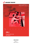
OSB 11
Swimming Starting Block
User’s Manual
3454.504.02
Version 1.3
Edition February 2014
Caution and safety precautions
Never use any other charger than the supplied or a type approved by Swiss Timing. This could
destroy the battery, cause damage to unit, and possible cause personal injury due to fire or/and
electrical shock.
Never bypass a power cord ground lead by breaking off the ground pin, or by using inappropriate
extension cords or adapters.
Never plug a power cord into the AC power source until you have made sure that all installation,
cabling and power levels, are proper, and that the applicable procedures in this manual have been
followed.
Protect the equipment against splashing, rain and excessive sun rays.
Never use the device if it is damaged or insecure.
Verify the selection of the power distribution.
Verify that the voltage quoted on the rating plate is the same as your voltage. Connect the appliance
only to power sockets with protective earth. The use of incorrect connection voids warranty.
This program may be modified at any time without prior notification.
Do not open the case; there is nothing that needs servicing inside it. Nevertheless, if the case must
be opened, you must call for some qualified personnel. The power supply cable must be
disconnected before opening the case.
During the transport of all Swiss Timing equipment delivered with a reusable carry case, the said
case should be used at all times. This is imperative to limit the damage, such as shocks or vibration
that can be caused to the units during transport.
The same cases should also be used when returning equipment to Swiss Timing for repair. Swiss
Timing reserves the right to refuse all guarantees if this condition is not fulfilled.
If the installation includes a horn, be sure to maintain a sufficient security distance from the public.
Documentation Updates
Swiss Timing Ltd. reserves the right to make improvements in the products described in this documentation
at any time without prior notice. Furthermore, Swiss Timing Ltd. reserves the right to revise this
documentation in its content at any time and without any obligation to notify any person or organization of
such revision.
Disclaimer
The information provided in this documentation has been obtained from sources believed to be reliable,
accurate and current. However, Swiss Timing Ltd. makes no representation or warranty, express or implied,
with respect, but not limited to, the completeness, accuracy, correctness and actuality of the content of this
documentation. Swiss Timing Ltd. specifically disclaims any implied warranty of merchantability, quality
and/or fitness for any particular purpose. Swiss Timing Ltd. shall not be liable for errors contained in this
documentation or for incidental or consequential damages in connection with the supply, performance or use
of this documentation.
Environment
This symbol indicates that this product should not be disposed with household waste. It has to be
returned to a local authorized collection system. By following this procedure you will contribute to
the protection of the environment and human health. The recycling of the materials will help to
conserve natural resources.
Copyright
© Swiss Timing Ltd.
All rights reserved.
This documentation may not, as a whole or in part, be copied, translated, reproduced, transmitted or reduced
and/or stored to any electronic medium or machine-readable form without the prior written consent of Swiss
Timing Ltd.
Swimming Starting Block / OSB 11
TABLE OF CONTENTS
1
2
INTRODUCTION........................................................................................................... 1
1.1
Construction of the OSB11-RBD starting block (Relay Break Detection) ...................... 2
1.2
Construction of the OSB11 starting block without start control ...................................... 3
1.3
Fixation material of the starting block ............................................................................ 4
INSTALLATION ............................................................................................................ 5
2.1
Positioning of the OSB11 starting blocks ...................................................................... 5
2.2
Fixation of the starting block ......................................................................................... 6
2.3
Drilling and mounting of the OSB11 .............................................................................. 6
3
TECHNICAL CHARACTERISTICS OF THE OSB11-SW WITH RELAY BREAK
DETECTION (RBD) AND WITHOUT START CONTROL ............................................ 7
4
CONTROL AND MAINTENANCE OF THE STARTING BLOCK ................................. 8
4.1
Control without application of pressure ......................................................................... 8
4.2
Pressure sensitivity control ........................................................................................... 8
4.3
Connection to the timing system ................................................................................... 8
4.4
Inspection ..................................................................................................................... 9
4.5
Troubleshooting (detection of a short circuit) ................................................................ 9
4.6
Troubleshooting (no contact) ........................................................................................ 9
4.7
Sensitivity adjustment ................................................................................................... 9
4.8
Assembly of the RBD and platform ............................................................................. 10
4.9
Dismantling of the top ................................................................................................. 11
5
PREVENTION AND MAINTENANCE
................................................................ 13
6
APPENDIX .................................................................................................................. 15
6.1
Abbreviations and symbols ......................................................................................... 15
6.2
Index figures ............................................................................................................... 15
6.3
Version history ............................................................................................................ 15
SWISS TIMING LTD
P.O. Box 138, rue de l'Envers 1
CH-2606 Corgémont
Switzerland
Phone +41 32 488 36 11
www.swisstiming.com
[email protected]
Swimming Starting Block / OSB 11
1 INTRODUCTION
OBS11 presents a powerful new patented feature, revolutionising the way the swimmers start from
their blocks. Diving from the starting block with the body propelled by the knee at a 90° angle
drastically increases the explosiveness of the start. Physical tests undertaken by top level
swimmers showed faster races versus a standard block.
OSB11 starting blocks have been tested by world-class swimmers, who have helped to specify the
optimum angles of both the platform and the footrest for racing starts. Design research also applied
to the top surfaces, very comfortable yet rough enough to guarantee the swimmer a feeling of total
security. The length of the platform is extended to 74cm to accommodate to the new styles of start.
The diameter and position of the handgrips have also been carefully considered to respond to all
the requirements of different hand positions. A door at the back of the block allows easy access to
the interior to connect the cabling. .
OSB11 starting blocks benefit from a new design and an attractive color scheme.
Version 1.3
3454.504.02
Page 1
1.1
Construction of the OSB11-RBD starting block (Relay Break Detection)
1. 3454.013
Starting block
2. 3454.014
Rear door
3. 3454.012
Platform with footrest
4. 3454.600
Complete RBD
3454.010
Upper frame
3454.011
Lower frame
2659.056
Rubber shock absorber (Silentblock)
3393.018
Spring loaded contact
3393.019
Contact screw
3393.020
Adjustment screw
3393.021
Isolation plate
3393.022
Isolation washer
3393.601
Connection cable
5. A4 self-blocking nut M8 (9557.1505) + A4 washer M8 (9580.1614) for platform fixing
6. 3454.015
Handle
7. Fixation material (see paragraph 1.3)
3454.716
Material 6 lines
3454.718
Material 8 lines
3454.720
Material 10 lines
Figure 1 - OSB11-RBD
Page 2
3454.504.02
Version 1.3
Swimming Starting Block / OSB 11
1.2
Construction of the OSB11 starting block without start control
1. 3454.013
Starting block
2. 3454.014
Rear door
3. 3454.012
Platform with footrest
4. 3454.019
Intermediate plate
5. A4 self-blocking nut M8 (9557.1505) + A4 washer M8 (9580.1614)
6. 3454.015
Handle
7. Fixation material (see paragraph 1.3)
3454.716
Material 6 lines
3454.718
Material 8 lines
3454.720
Material 10 lines
Figure 2 - OSB11 without start control
Version 1.3
3454.504.02
Page 3
1.3
Fixation material of the starting block
1. 3454.030
2. 9051.9803
9051.9008
9051.9814
3. 9039.8582
4. 3454.032
5. 3454.031
Drilling gauge
Drill ∅5
Drill ∅10
Drill ∅16
Anchor with internal thread M8 x 90 (4x)
Stainless steel washer M8 (4x)
Hexagon head stainless steel screw M8 x 40 (4x)
Figure 3 - Fixation of the starting block
Page 4
3454.504.02
Version 1.3
Swimming Starting Block / OSB 11
2 INSTALLATION
2.1
Positioning of the OSB11 starting blocks
The OSB11 starting blocks are positioned according to the measures indicated: 400mm from the
swimming pool border (410mm with the OCP5 touchpad) to the front of the base.
The handle of the OSB11 must be aligned with the border of the touchpad (for example OCP5).
Are the touch plates missing or is the swimming pool too small with touchpads, align the OSB11
starting block with the border of the swimming pool.
The drilling oblong fixations permit a play of the block of +/-10mm; this permits a possible
correction of the alignment.
Swimming Pool as per
FINA regulations
Figure 4 - Positioning of the OSB11
Version 1.3
3454.504.02
Page 5
2.2
Fixation of the starting block
To ensure proper functioning of the OSB11 starting block system,
fixation must be absolutely rigid.
2.3
Drilling and mounting of the OSB11
For fix cabling, a hole with Ø120 - 122mm at 570mm away from the pool's border must be
foreseen in order to provide space for the cables (the gauge has a hole of Ø120mm).
Put the drilling gauge (1) on the border of the swimming pool and mark the 4 Ø5 holes of the
gauge with a Ø5 drill.
Drill the 4 holes respectively with drills ∅5, ∅10 and ∅16mm (2). Minimal depth: 90mm, maximal
depth: 100mm.
As per instruction manual 3393.505 "Preparing the drillings", push the pegs M8 (3) in the
∅16 holes and put the OSB11 starting block on the 4 fixation points.
Fix the base with the 4 screws M8 x 40 (5) and the 4 washers M8 (4).
Figure 5 - Fixation of the OSB11
Page 6
3454.504.02
Version 1.3
Swimming Starting Block / OSB 11
3 TECHNICAL CHARACTERISTICS OF THE OSB11-SW WITH RELAY
BREAK DETECTION (RBD) AND WITHOUT START CONTROL
OSB11-RBD
OSB11-Simple
DIMENSIONS
780 x 570 x 650
Platform 740mm x 520mm
WEIGHT (KG)
47
COLOURS
CONTACT
ACTION FORCE
CONNECTION
41
Platform white RAL 9010 with non-skidding
surface dark blue RAL 5002
Closing at the moment
of the start (NO)
13.0 Kg to 18.0Kg
Cable with 2-pole plug
(length ~140cm)
Figure 6 - Technical characteristics
Version 1.3
3454.504.02
Page 7
4 CONTROL AND MAINTENANCE OF THE STARTING BLOCK
4.1
Control without application of pressure
Connect the buzzer (11) to the connection cable (9). If there is no pressure on the
platform, the buzzer (11) remains silent. If the buzzer (11) emits a sound, proceed as
described in paragraph 4.5.
4.2
Pressure sensitivity control
Press with the Dynamometer (12) against the middle of the platform (3). Read on the
Dynamometer (12) the pressure necessary to activate the buzzer (11). If the sensitivity is out of the
range of 13kg and 18kg, see paragraph 4.7.
4.3
Connection to the timing system
If a satisfactory result has been obtained in tests 4.1 and 4.2, connect the connection
cable (9) to the timing system.
Figure 7 - Maintenance
Page 8
3454.504.02
Version 1.3
Swimming Starting Block / OSB 11
4.4
Inspection
Every 6 months:
check cable connections.
Once a year:
check rigidity of block fixation.
4.5
Troubleshooting (detection of a short circuit)
If the buzzer (11) emits a sound while there is no pressure on the platform, proceed as follows:
Unscrew the 4 nuts M8 (7) under the platform (3).
Remove platform (3) and connect the buzzer (11) to the connection cable (9).
Insert a screwdriver into the 2 holes of the lower frame (4) and unscrew each of the
adjustment screws (6) until they do not touch the contact head any more.
If the sound continues, verify if there is a short circuit on the cable or between the fixed and mobile
frame (mechanical or electrical connection).
4.6
Troubleshooting (no contact)
If the buzzer (11) does not emit a sound during the sensitivity adjustment, proceed as follows:
Make sure that the platform and the RBD are correctly assembled; there must be a visible
movement (Paragraph 4.8).
Make sure that the 2 adjustment screws are not too far apart.
4.7
Sensitivity adjustment
If the sensitivity is out of the range of 13kg and 18kg (as indicated in paragraph 4.2), make an
adjustment by proceeding as follows:
Connect the buzzer.
Insert a screwdriver in one of the holes of the lower frame (4) then screw the adjustment
screw (6), facet after facet of the hexagonal head until the buzzer emits a sound.
Unscrew the adjustment screw by turning it 4 facets backwards (0,16mm/facet).
Adjust the second screw in the same way.
Make a test with the Dynamometer (12) by pushing or pulling the upper frame (4).
If the measured pressure is higher than 18kg, continue screwing the screw in and test at
every facet.
If pressure is lower than 13kg, unscrew and test at every facet.
It is recommended to proceed systematically with the adjustment to obtain a regular play between
the 2 contacts.
Version 1.3
3454.504.02
Page 9
4.8
Assembly of the RBD and platform
When assembling the RBD and the platform, insert the screws but do not tighten them, push the
RBD to the maximum forwards (towards the handle) and tighten. Make sure the required distances
between the base and the RBD/platform are correct.
Required distance between base
and RBD: 21 to 22mm.
Do the same with the platform.
Required distance between base
and platform: 4 to 5mm.
Figure 8 - Assembly
Page 10
3454.504.02
Version 1.3
Swimming Starting Block / OSB 11
4.9
-
Dismantling of the top
Unscrew the platform by removing the 6 nuts indicated in green located under the top and
inside the base. Do not unscrew nuts indicated in red.
Instruction for dismantling the footrest
-
Position the footrest on number 3 to access the screws between the footrest and the guides.
Figure 9 - Dismantling of the footrest
Version 1.3
3454.504.02
Page 11
-
Rotate the top to access the lateral screws.
-
Unscrew the 4 screws (2 on each side).
Figure 10 - Dismantling of the footrest
-
Pull to remove the footrest then remove the guides.
-
To reassemble the footrest, start from this point and follow the instructions backwards.
Page 12
3454.504.02
Version 1.3
Swimming Starting Block / OSB 11
5
PREVENTION AND MAINTENANCE
Equipment installed in aquatic complex, often sealed with a high moisture level, require special
attention in regards to their maintenance. In fact, the stainless steel parts found on ladders, fences
or swimming starting blocks can have corrosion if they are not frequently cleaned.
REMEDIATION
MAINTENANCE
Stainless steel is an excellent product that needs to be very clean to keep its stainless
quality.
When you receive your new equipment, it is important to establish a maintenance
program to avoid the stainless steel parts to deteriorate. Indeed, lack of maintenance
can make the chromium oxide film inefficient, which could cause corrosion on your
equipment. A dirty surface is the biggest ally of corrosion and your biggest enemy.
Dirt, grease and deposit left by users or by contaminated water deposit must be removed by
cleaning the surface with fresh water (do not use the pool’s water) using a high-pressure
cleaner and wiping, if possible, with a clean dry cloth.
A basic cleaning of the starting blocks’ inner and outer surfaces (without disassembly) must
be done regularly, preferably every week, if possible using a high pressure cleaner.
A thorough cleaning with removal of the top (see manual) must be done regularly, several
times a year, depending on the degree of contamination of the stainless steel. You must pay
extra attention to the RBD (Relay Break Detection) and the handles (backstroke start).
Concerning dismantling, it is imperative to use tools that are specially dedicated to stainless
steel.
If your equipment is already showing significant dirt deposits, you need to get rid of
them in order that the oxygen from the air gets in contact with the chromium in the
stainless steel to form the protective chromium oxide film.
A thorough cleaning with fresh water using a high-pressure cleaner is normally sufficient. If
some dirt remains, rub with a nylon pad or a cotton cloth. Make sure the pad you use is not
rough to prevent it damaging the protective film or the aesthetic finish of the product.
After a thorough cleaning, clean the stainless steel with fresh water twice a week during a
few months and then decrease the frequency.
Never use a metal brush, steel wool, emery paper or any abrasive material to clean. Indeed,
stainless steel would be contaminated by a large quantity of undesirable particles which
inevitably would cause rust stains.
OSB properly maintained
Version 1.3
OSB poorly maintained
3454.504.02
Page 13
REMINDER
•
•
•
•
•
•
A weekly basic cleaning is required.
A thorough cleaning must be done regularly, several times a year.
You must use fresh water for cleaning.
Never use abrasive material to clean the stainless steel parts.
Drying the stainless steel parts must be done using a clean dry cloth.
Use specially dedicated stainless steel tools for dismantling the starting blocks.
Page 14
3454.504.02
Version 1.3
Swimming Starting Block / OSB 11
6 APPENDIX
6.1
Abbreviations and symbols
Abbreviations
Symbols
6.2
Index figures
Figure 1 - OSB11-RBD ................................................................................................................... 2
Figure 2 - OSB11 without start control ............................................................................................ 3
Figure 3 - Fixation of the starting block ........................................................................................... 4
Figure 4 - Positioning of the OSB11 ................................................................................................ 5
Figure 5 - Fixation of the OSB11 ..................................................................................................... 6
Figure 6 - Technical characteristics ................................................................................................. 7
Figure 7 - Maintenance ................................................................................................................... 8
Figure 8 - Assembly ...................................................................................................................... 10
Figure 9 - Dismantling of the footrest ............................................................................................ 11
Figure 10 - Dismantling of the footrest .......................................................................................... 12
6.3
Version history
Version
Date
Modifications since last version
1.0
01/01/10
Initial version
1.1
01/06/10
Minor modifications
1.2
14/07/11
Modifications references washers and screws. Modification of action
force. New canevas.
1.3
20/02/14
Change drawing chapter 4.9 (dismantling of the top). Addition of
chapter 5 Prevention and Maintenance
Version 1.3
3454.504.02
Page 15
NOTES
Page 16
3454.504.02
Version 1.3
SWISS TIMING LTD
P.O. Box 138, rue de l'Envers 1
CH-2606 Corgémont
Switzerland
Phone +41 32 488 36 11
www.swisstiming.com
[email protected]