1
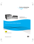
User‘s Manual
PROFIBUS-DP
Interface for Encoders
English (en)
7/2014
Contents
Contents
List of tables .......................................................................................................................... 4
List of figures......................................................................................................................... 5
1
General information....................................................................................................... 6
1.1 Encoder gateway.................................................................................................... 6
1.2 Absolute encoders ................................................................................................. 6
1.3 PROFIBUS technology ........................................................................................... 7
1.3.1 PROFIBUS DP functionality levels ............................................................. 7
1.3.2 References.................................................................................................. 8
1.3.3 Abbreviations .............................................................................................. 8
2
Encoder gateway installation ....................................................................................... 9
2.1 Settings inside the gateway ................................................................................... 9
2.1.1 Node address ............................................................................................ 10
2.1.2 Bus termination ......................................................................................... 11
2.2 Power supply .........................................................................................................12
2.3 BUS lines ...............................................................................................................14
2.4 Shielding philosophy..............................................................................................16
2.5 GSD file..................................................................................................................16
2.6 LED indication....................................................................................................... 18
3
Absolute encoder installation .................................................................................... 19
3.1 Settings inside the encoder ..................................................................................19
3.1.1 Node address ............................................................................................19
3.1.2 Bus termination ........................................................................................ 20
3.2 Connecting the encoder....................................................................................... 21
3.2.1 Bus lines ................................................................................................... 23
3.3 Shielding philosophy............................................................................................. 25
3.4 GSD file................................................................................................................. 25
3.5 LED indication....................................................................................................... 27
4
Profile overview, DPV0 version 1.1............................................................................. 28
4.1 DPV0 encoder classes ......................................................................................... 29
2
Contents
5
Encoder and Gateway functionality, DPV0 .............................................................. 31
5.1 Basic functionality................................................................................................. 31
5.2 PROFIBUS data transfer principle........................................................................ 31
5.2.1 During Configuration (DDLM_Chk_Cfg mode)........................................ 31
5.2.2 During Parameterization (DDLM_Set_Prm mode) .................................. 31
5.2.3 Normal operation (DDLM_Data_Exchange mode) .................................. 32
5.3 Configuration, DPV0 ............................................................................................. 32
5.4 Parameterization, DPV0 ....................................................................................... 32
5.4.1 Code sequence......................................................................................... 34
5.4.2 Class 2 functionality.................................................................................. 34
5.4.3 Commissioning diagnostics ..................................................................... 34
5.4.4 Scaling function control ............................................................................ 35
5.4.5 Measuring units per revolution ................................................................ 35
5.4.6 Total measuring range (units) ................................................................... 37
5.4.7 Velocity control.......................................................................................... 38
5.4.8 Velocity calculation.................................................................................... 39
5.5 Data transfer in normal operation (DDLM_Data_Exchange) ............................... 40
5.5.1 Data exchange mode ............................................................................... 40
5.5.2 Preset function ......................................................................................... 41
5.6 Diagnostics ........................................................................................................... 43
5.6.1 Diagnostic Header .................................................................................... 45
5.6.2 Alarms ....................................................................................................... 45
5.6.3 Operating Status....................................................................................... 47
5.6.4 Encoder type............................................................................................. 48
5.6.5 Singleturn resolution or measuring step .................................................. 49
5.6.6 Number of distinguishable revolutions .................................................... 49
5.6.7 Additional alarms ...................................................................................... 50
5.6.8 Supported alarms ..................................................................................... 50
5.6.9 Warnings ................................................................................................... 51
5.6.10 Supported warnings ................................................................................. 52
5.6.11 Profile Version ........................................................................................... 53
5.6.12 Software Version ....................................................................................... 53
5.6.13 Operating time.......................................................................................... 54
5.6.14 Offset value............................................................................................... 55
5.6.15 Offset value of the encoder manufacturer............................................... 55
5.6.16 Scaling parameters settings ..................................................................... 56
5.6.17 Encoder serial number ............................................................................. 57
6
Encoder commissioning example, DPV0 ................................................................. 58
7
Revision history ............................................................................................................ 61
3
List of tables
List of tables
Table 1
Table 2
Table 3
Table 4
Table 5
Table 6
Table 7
Table 8
Table 9
Table 10
Table 11
Table 12
Table 13
Table 14
Table 15
Table 16
Table 17
Table 18
Table 19
Table 20
Table 21
Table 22
Table 23
Table 24
Table 25
Table 26
Table 27
Table 28
Table 29
Table 30
Table 31
Table 32
Table 33
Table 34
Table 35
Table 36
Table 37
Table 38
4
Termination switch settings.........................................................................11
Pinning M12 power supply connector ....................................................... 12
Pinning M12 bus in/out connectors ........................................................... 14
Available GSD file for DPV0 gateway ......................................................... 16
LED indication ............................................................................................. 18
Terminating switch settings........................................................................ 20
Pinning M12 power supply connector ....................................................... 21
Pinning M12 bus in/out lines ...................................................................... 23
Available GSD file for DPV0 encoders........................................................ 25
LED indication encoder .............................................................................. 27
Operating parameters in DPV0 .................................................................. 32
Octet9, Parameter definition ...................................................................... 33
Singleturn scaling parameters format ........................................................ 36
Multiturn scaling parameters format.......................................................... 36
Octet 39 Velocity Control ............................................................................ 39
Data exchange 32-bits ................................................................................ 40
Data exchange -16 bits ............................................................................... 41
Preset value, 32-bit format ......................................................................... 42
Preset value, 16-bit format.......................................................................... 42
Diagnostic message, DPV0........................................................................ 44
Diagnostic header ....................................................................................... 45
Alarms ......................................................................................................... 46
Operating status ......................................................................................... 47
Diagnostic, encoder .................................................................................... 48
Diagnostic, singleturn resolution ................................................................ 49
Diagnostics, number of distinguishable revolutions .................................. 49
Diagnostics, additional alarms .................................................................... 50
Diagnostics, supported alarms................................................................... 50
Diagnostics, warnings ................................................................................ 51
Diagnostics, supported warnings............................................................... 52
Diagnostics, profile version ........................................................................ 53
Diagnostics, software version .................................................................... 54
Diagnostic, operating time ......................................................................... 54
Diagnostics, offset value ............................................................................ 55
Diagnostics, offset value of the encoder manufacturer ............................ 55
Diagnostics, scaling parameter setting ...................................................... 56
Diagnsotics, encoder serial number........................................................... 57
Revision history........................................................................................... 61
General information
List of figures
Figure 1
Figure 2
Figure 3
Figure 4
Figure 5
Figure 6
Figure 7
Figure 8
Figure 9
Figure 10
Figure 11
Figure 12
Figure 13
Figure 14
Figure 15
Placement of screws .................................................................................... 9
PCB-view of a cable gland PROFIBUS gateway........................................ 10
Orientation of M12 power supply connector............................................. 12
Terminal connections of power supply cables ........................................... 13
Orientation of M12 bus connectors ........................................................... 14
Terminal connections of bus line cables .................................................... 15
PCB-view of a cable gland encoder ........................................................... 19
Orientation of M12 power supply connector............................................. 21
Terminal connections of power supply cables ........................................... 22
Orientation of M12 bus connectors ........................................................... 23
Terminal connections of bus line cables .................................................... 24
Overview encoder profile and related documents .................................... 28
Basic functionality ....................................................................................... 31
Cyclic scaling ............................................................................................... 37
Non-cyclic scaling........................................................................................ 38
5
General information
1
General information
This manual describes the installation procedures and
configuration of HEIDENHAIN absolute encoders and encoder
gateways with PROFIBUS DPV0 functionality.
1.1 Encoder gateway
The advantages of the gateway concept is that it allows the use
of small and very robust EnDat encoders, which make the
encoder gateway solution suitable in applications where very high
ambient temperature is a limiting factor.
Another benefit with the gateway solution is that in case of an
encoder error occurs, the EnDat encoder can easily be replaced
without the need to disconnect the PROFIBUS line. The encoder
gateway supports singleturn encoders with up to 31 bit resolution
and multiturn encoders with up to 37 bits resolution with the
limitations described in this manual.
1.2 Absolute encoders
With an absolute encoder each angular position is assigned a
coded position value generated by a code disc equipped with
several parallel fine graduations tracks which are scanned
individually. On singleturn encoders, i.e. an encoder producing
absolute positions within one revolution, the absolute position
information repeats itself with every revolution. So called multiturn
encoders can also distinguish between revolutions. The numbers
of unique revolutions is determined by the resolution of the
multiturn scanning and repeats itself after the total resolution is
reached.
6
General information
1.3 PROFIBUS technology
PROFIBUS is a powerful and versatile 2-wire non-proprietary open
field bus standard defined by several international standards such
as EN 50170, IEC 61158 together with different device profiles.
There are 3 different PROFIBUS versions available today, DP, FMS
and PA. HEIDENHAIN products support the Decentralized
Peripherals (DP) version. In addition to manufacturer-specific
functions, the HEIDENHAIN devices described in this manual
supports class 1 and 2 according to the encoder profile 3.062. The
encoder device profile describing encoder functionality and
additional information about PROFIBUS can be ordered from
PROFIBUS User Organization, PNO.
PROFIBUS User Organization
Haid-und-Neu Straße 7
D 76131 Karlsruhe, Germany
Tel: +49 721 96 58 590
Fax: + 49 721 96 58 589
Web: www.profibus.com
1.3.1
PROFIBUS DP functionality levels
The main functions of the different levels are as follows:
DPV0: Supports the basic functionality for the PROFIBUS
protocol. In principal this means the cyclical I/O communication
and diagnostics. This manual only covers DPV0 functionality.
DPV1: The most important benefits with DPV1 are the expanded
functions for the acyclical data communication and alarm
handling. This is a precondition for parameterization and calibration
of field devices over the bus in runtime. HEIDENHAIN have a
separate manual for DPV1/DPV2 devices.
DPV2: In addition to the functionality above, DPV2 includes
expansions that are required for time critical applications such as
motion control. This means functions such as slave-to-slave
communications and isochronous data exchange (time
synchronization). HEIDENHAIN have a separate manual for
DPV1/DPV2 devices.
7
General information
1.3.2
References
Profile Encoder V1.1, Order No. 3.062
1.3.3
8
Abbreviations
PROFIBUS
Process Field Bus
PI
PROFIBUS and Profinet International
PNO
PROFIBUS Nutzerorganisation e.V.
GSD
German term "Gerätestammdaten". A GSD is the
device database file, also called device
datasheet.
DP
Decentral Periphery
Input data
Data which the master receives from the
encoder
Output data
Data which the encoder receives from the
master.
PDU
Protocol Data Unit
DDLM
Direct Data Link Mapper, the interface between
PROFIBUS-DP functions and the encoder
software
DDLM_Set_Prm
Interface during parameterization
DDLM_Data_Exchange
DDLM_Slave_Diag
Interface during data exchange
Interface during diagnostics data transfer
DDLM_Chk_Cfg
Interface during configuration
Encoder gateway installation
2
Encoder gateway installation
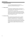
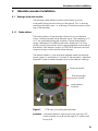
2.1 Settings inside the gateway
The encoder gateway addressing switches and bus termination
must be configured during commissioning of the device. This is
done by removing the back cover, i.e. screwing off the three
screws at the rear of the gateway.
Screws to remove
back cover
Figure 1
Placement of screws
9
Encoder gateway installation
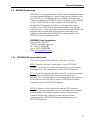
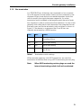
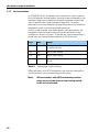
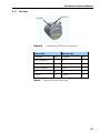
2.1.1
Node address
The node address of the encoder gateway can be set via three
decimal rotary switches located inside the back cover. The
weighting, x100, x10 and x1 are specified on the circuit board
besides the switches. Permissible address range is between 0
and 126 but the lower addresses 0 to 2 are usually used by the
master and not recommended to be used by the device. Each
address used in a PROFIBUS network must be unique and may
not be used by other devices.
The device address is only read and adopted when the gateway
power supply is switched on. A restart of the gateway is therefore
required in order to adopt changes done to the address settings.
Screw terminals
Bus termination
switch (on/off)
Node address
switches ()
Figure 2
PCB-view of a cable gland PROFIBUS gateway
Example: To set the node address to 115, the switch to the left
(x100) shall be set to 1, the switch in the middle(x10)
should also be set to 1 and the switch to the right(x1)
shall be set to 5.
10
Encoder gateway installation
2.1.2
Bus termination
In a PROFIBUS net, all devices are connected in a bus structure.
Up to 32 devices (master and/or slaves) can be connected in one
segment. When more devices are needed repeaters should be
used to amplify the signals between segments. An active
termination must be added in the beginning and the end of each
bus segment in order to ensure error-free operation. In case of the
gateway with cable glands such terminators are integrated inside
the back cover and can be activated via dip switches as shown in
figure 2. If the device is un-powered the A and B lines are
internally terminated by a 220 Ω resistor.
Bit1
Bit2
Effect
On
On
There is a 220 ohms resistor between bus
A and bus B line.
On
Off
Not a valid setting
Off
On
Not a valid setting
Off
Off
There is no resistor between bus A and
bus B line.
Table 1
Termination switch settings
When encoder gateways with M12 connectors are used the
termination should be done using a M12 terminating resistor plug.
Note:
When M12 terminating resistor plugs are used, the
internal terminating switch shall not be activated.
11
Encoder gateway installation
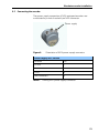
2.2 Power supply
The power supply connection of M12 equipped gateways are
constituted by a male A-coded 4 pin M12 connector.
Power supply
Figure 3
Orientation of M12 power supply connector
Power supply M12 version
Function
Pin
+E Volt
1
Not connected
2
0 Volt
3
Not connected
4
Table 2
12
Pinning M12 power supply connector
Encoder gateway installation
Encoder gateways equipped with cable glands are delivered with
a dust protection foil from the factory. The protection foil needs to
be removed prior to installing the cables.
It is recommended that gateways equipped with cable glands are
equipped with a shielded power supply cable with conductor area
between 0,34 mm2 to 1.5 mm2. Permissible outer cable diameter
is ø 6 mm to ø 8 mm for the power supply cable. The power
supply screw terminal is located inside the back cover of the
gateway.
In the case were the gateway is the last node in the bus-structure
and only the cable glands for Supply and Bus-in is in use, the Bus
out cable gland should be replaced with a M16 filler plug to
ensure proper sealing.
The +E terminal shall be used to connect +E Volt.
The 0 V terminal shall be used to connect 0 Volt.
Figure 4
Terminal connections of power supply cables
Note:
Tighten all screws in the terminal, even if no cable
has been attached.
Note:
The two +E terminals are connected to each other
and the two 0 V terminals are also connected to
each other, i.e it does not matter to which pair the
+E Volt and 0 Volt are connected to.
13
Encoder gateway installation
2.3 BUS lines
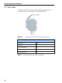
The PROFIBUS bus line connections of the M12 equipped
devices are constituted by a male B-coded 5 pin M12 connector
(bus in), and a female B-coded 5 pin M12 connector (bus out).
Bus in
Bus out
Orientation of M12 bus connectors
Figure 5
Bus in line
Function
Pin
Function
Pin
Not connected
1
VP
1
A
2
A
2
Not connected
3
DGND
3
B
4
B
4
Chassis
5
Chassis
5
Table 3
14
Bus out line
Pinning M12 bus in/out connectors
Encoder gateway installation
The cable gland gateway shall be equipped with twisted pair
shielded cable in accordance with EN 50170 and PROFIBUS
guidelines. The guidelines recommend a conductor area higher
than 0,34 mm2. Permissible outer cable diameter is ø 8 mm to
ø 10 mm for the bus lines cables. Located inside the back cover
are four screw terminals containing the required bus line
terminals marked A and B. Cable glands not used, should be
replaced with a M16 filler plug to ensure proper sealing.
Figure 6
Terminal connections of bus line cables
Note:
Tighten all screws in the terminal, even if no cable
has been attached.
Note:
The two A terminals are internally connected to
each other and the two B terminals are also
connected to each other so it does not matter to
which the bus lines are connected to.
15
Encoder gateway installation
2.4 Shielding philosophy
To achieve the highest possible noise immunity and resistance
against other EMI related disturbances the bus and power supply
cables shall always be shielded. The screen should be connected
to ground on both ends of the cable. In certain cases
compensation current might flow over the screen. Therefore a
potential compensation wire is recommended.
2.5 GSD file
PROFIBUS Gateways can be configured and parameterized
corresponding to the requirements of the user. When the system
is started, the PROFIBUS devices are set and configured in
DDLM_Set_Prm mode, i.e the application class set by means of
the GSD file in the configuration tool and the operating
parameters are transferred to the respective slave.
Available GSD files can be downloaded from
www.heidenhain.com
GSD file
Gateway functionality
GSD file
Gateway PROFIBUS DPV0
(For rotary encoders)
ENC_A400
Table 4
Available GSD file for DPV0 gateway
When configuring the gateways two device classes (Class 1
or Class 2) can be selected as described in chapter 4.
Selectable parameters and functionality of the device depend
on the selected encoder class. This data, saved in the
PROFIBUS master is transferred once to the gateway when
the system is powered on. If the gateway has been started
with one GSD file and a new GSD file with a different IDnumber shall be used, the gateway needs to be restarted
before it can use the new GSD file.
After the configuration and parameter data have been received,
the gateway enters normal operation with cyclic data transfer i.e.
“DDLM_Data_Exchange mode”.
16
Encoder gateway installation
Installation of GSD-files:
1)
Select and save the GSD file for the respective device from
www.heidenhain.com and then copy the *.gsd file into the respective
directory of the PROFIBUS configuration tool.
2)
Select the bitmap file of the respective device and copy the *.bmp file into the
respective directory of the PROFIBUS configuration tool.
3)
Update the GSD files (SCAN).
17
Encoder gateway installation
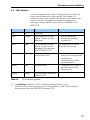
2.6 LED indication
In order to determine the status of the gateway two LEDs are
visible on the front of the gateway. The module LED indicates
status of the module itself. The bus LED indicates the status of
the bus. The table below defines the diagnostic messages using a
bi-colored red/green LED for bus and module.
Bus status
Module
Meaning
Off
Off
No power
Red
Green
No connection to other
device. Criteria: No data
exchange
- Bus disconnected
- Master not
available/switched off
Red2)
Red2)
No connection to other
device. No connection
between EnDat encoder and
PROFIBUS PCB.
No connection to EnDat
encoder at power up.
Blinking1)
Green
Parameterization or
configuration fault
- Configuration received
differs from the supported
configuration.
- Parameter error in the
parameterization.
Green
Red
System failure
- Diagnosis exists, slave in
data exchange mode.
Green
Green
Data exchange and encoder
function properly.
Table 5
1)
2)
18
Cause
LED indication
The blinking frequency is 0.5 Hz. Minimal indication time is 3 sec.
Position error is when an alarm occurs in the encoder or if the EnDat encoder is
disconnected from the PROFIBUS interface PCB.
Absolute encoder installation
3
Absolute encoder installation
3.1 Settings inside the encoder
The encoder node address and bus termination must be
configured during commissioning of the device. This is done by
removing the back cover, i.e. screwing off the three screws at the
rear of the encoder.
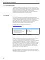
3.1.1
Node address
The node address of the encoder can be set via two decimal
rotary switches located inside the back cover. The weighting, x10
or x1 are specified beside the switches. Permissible address
range is between 0 and 99 but the lower addresses 0 to 2 are
usually used by the master and not recommended to be used by
the device. Each address used in a PROFIBUS network must be
unique and may not be used by other devices.
The device address is only read and adopted when the encoder
power supply is switched on. A restart of the encoder is therefore
required in order to adopt changes done to the address settings.
Screw terminals
Bus termination
switch (on/off)
Node address
switches
Figure 7
PCB-view of a cable gland encoder
Example: If the node address shall be set to 85, the left (x10)
switch shall be set to 8 and the right (x1) switch shall
be set to 5.
19
Absolute encoder installation
3.1.2
Bus termination
In a PROFIBUS net, all devices are connected in a bus structure.
Up to 32 devices (master and/or slaves) can be connected in one
segment. When more devices are needed repeaters should be
used to amplify the signals between segments. An active
termination must be added in the beginning and end of each bus
segment in order to ensure error-free operation.
In case of the encoder with cable glands such terminators are
integrated inside the back cover and can be activated via dip
switches as shown in figure 7. If the device is un-powered the A
and B lines are internally terminated by a 220 Ω resistor.
Bit1
Bit2
Effect
On
On
There is a 220 ohms resistor between bus
A and bus B line.
On
Off
Not a valid setting
Off
On
Not a valid setting
Off
Off
There is no resistor between bus A and bus
B line.
Table 6
Terminating switch settings
When encoders with M12 connectors are used the termination
should be done using a terminating resistor plug.
Note:
20
When encoders with M12 terminating resistor
plugs are used, the internal terminating switch
shall not be activated.
Absolute encoder installation
3.2 Connecting the encoder
The power supply connection of M12 equipped encoders are
constituted by a male A-coded 4 pin M12 connector.
Power supply
Figure 8
Orientation of M12 power supply connector
Power supply M12 version
Function
Pin
+E Volt
1
Not connected
2
0 Volt
3
Not connected
4
Table 7
Pinning M12 power supply connector
21
Absolute encoder installation
Encoders equipped with cable glands are delivered with a dust
protection foil from the factory. The protection foil needs to be
removed prior to install the cables.
It is recommended that encoders with cable gland are equipped
with a shielded power supply cable with conductor area between
0,34 mm2 to 1.5 mm2. Permissible outer cable diameter is
ø 6 mm to ø 8 mm for the power supply cable. Located inside the
back cover are two screw terminals containing the required power
supply terminals marked (+) and (-). In the case were the encoder
is the last node in the bus-structure and only the cable glands for
Supply and Bus-in is in use, the Bus out cable gland should be
replaced with a M16 filler plug to ensure proper sealing.
The (+) terminal shall be used to connect the +EV-line.
The (-) terminal shall be used to connect the 0 V-line.
Figure 9
Note:
22
Terminal connections of power supply cables
Tighten all screws in the terminal, even if no cable
has been attached.
Absolute encoder installation
3.2.1
Bus lines
Bus in
Bus out
Orientation of M12 bus connectors
Figure 10
Bus in line
Bus out line
Function
Pin
Function
Pin
Not connected
1
VP
1
A
2
A
2
Not connected
3
DGND
3
B
4
B
4
Chassis
5
Chassis
5
Table 8
Pinning M12 bus in/out lines
23
Absolute encoder installation
The cable gland encoders shall be equipped with twisted pair
shielded cable in accordance with EN 50170 and PROFIBUS
guidelines. The guidelines recommend a conductor area higher
than 0,34 mm2. Permissible outer cable diameter is ø 8 mm to
ø 10 mm for the bus line cables. Located inside the back cover are
four screw terminals containing the required bus line terminals
marked (A) and (B). Cable glands not used should be replaced
with a M16 filler plug to ensure proper sealing.
The (A) terminal shall be used to connect the A-line.
The (B) terminal shall be used to connect the B-line.
Figure 11
24
Terminal connections of bus line cables
Note:
Tighten all screws in the terminal, even if no cable
has been attached.
Note:
The two A terminals are internally connected to
each other and the two B terminals are also
connected to each other so it does not matter to
which terminal the bus lines are connected to.
Absolute encoder installation
3.3 Shielding philosophy
To achieve the highest possible noise immunity and resistance
against other EMI related disturbances the bus and power supply
cables shall always be shielded. The screen should be connected
to ground on both ends of the cable. In certain cases
compensation current might flow over the screen. Therefore a
potential compensation wire is recommended.
3.4 GSD file
Absolute encoders with PROFIBUS can be configured and
parameterized corresponding to the requirements of the user.
When the system is started, the PROFIBUS devices are set and
configured in DDLM_Set_Prm mode, i.e. the encoder class set by
means of the GSD file in the configuration tool and the operating
parameters are transferred to the respective slave.
Available GSD files can be downloaded from
www.heidenhain.com.
GSD file
Gateway functionality
GSD file
Absolute encoder PROFIBUS DPV0
Enc_A401
Table 9
Available GSD file for DPV0 encoders
The GSD data is saved in the PROFIBUS master and transferred
once to the encoder when the system is powered on. If the
encoder has been started with one GSD file and a new GSD file
with a different ID-number shall be used, the encoder needs to be
restarted before it can use the new GSD file.
After the configuration and parameter data have been
received, the gateway enters normal operation with cyclic
data transfer i.e. “DDLM_Data_Exchange mode”.
25
Absolute encoder installation
Installation of GSD-files:
26
1)
Select and save the GSD file for the respective device from
www.heidenhain.com and then copy the *.gsd file into the respective
directory of the PROFIBUS configuration tool.
2)
Select the bitmap file of the respective device and copy the *.bmp file into the
respective directory of the PROFIBUS configuration tool.
3)
Update the GSD files (SCAN).
Absolute encoder installation
3.5 LED indication
In order to determine the status of the encoder two LEDs are
visible from the rear end of the encoder. The module LED
indicates status of the module itself. The bus LED indicates the
status of the bus. The table below defines the diagnostic
messages using a red (BUS) and a bicolor, Red/Green, LED
(MODULE).
Bus status
Module
Meaning
Off
Off
No power
Red
Green
No connection to other
device. Criteria :No data
exchange
- Bus disconnected
- Master not available/
switched off
Red2)
Red2)
No connection to other
device. No connection
between EnDat encoder
and PROFIBUS PCB.
No connection to EnDat
encoder at power up.
Blinking1)
Green
Parameterization or
configuration fault
- Configuration received
differs from the supported
configuration.
- Parameter error in the
parameterization.
Green
Red
System failure
- Diagnosis exists, slave in
data exchange mode.
- Position error
Green
Green
Data exchange. Slave and
operation OK
Table 10
1)
2)
Cause
LED indication encoder
The blinking frequency is 0.5 Hz. Minimal indication time is 3 sec.
Position error is when an alarm occurs in the encoder or if the EnDat encoder is
disconnected from the PROFIBUS interface PCB.
27
Profile overview, DPV0 version 1.1.
4
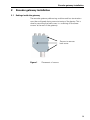
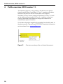
Profile overview, DPV0 version 1.1.
The operating function in this profile is divided into two device
classes named Class 1 and Class 2. Class 1 encoders offer basic
functions that all PROFIBUS-DP encoders must support.
Encoders of Class 2 must support all functions of Class 1 as well
as the additional functionality of Class 2. In addition to the two
classes, parameters and diagnostic ranges are reserved for
manufacturer-specific functions.
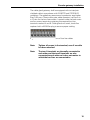
For further information regarding the encoder functionality refer to
the device profile. The profile and PROFIBUS technical information
can be ordered from www.profibus.com.
Figure 12
28
Overview encoder profile and related documents
Profile overview, DPV0 version 1.1.
4.1 DPV0 encoder classes
The device can be configured as a class 1 or class 2
PROFIBUS slave device. Class 2 configuration is extended to
optionally access velocity information from the encoder.
CLASS 1
In the CLASS 1 configuration, only input data are assigned.
Depending on the encoder resolution, this is one input data
word (16 bits) or two (32 bits).
The following functions can be performed:
1) Changed direction of counting
(Code sequence)
2) Diagnostic data up to octet 16
Configuration data:
Singleturn Class 1 – 16 Bit: D0hex, 1 input data word,
data consistency
Multiturn Class 1 – 32 Bit: D1hex, 2 input data words,
data consistency
CLASS 2
In the CLASS 2 configuration output data values and input
data words are transferred. Depending on the encoder
resolution, this is one input data word (16 bits) and one output
data word (16 bits) or two input data words (32 bits) and two
output data words (32 bits).
The following functions are available in addition to the class 1
functions:
1) Scaling function
2) Preset Value Function
3) Velocity read-out
4) Extended diagnostic data
29
Profile overview, DPV0 version 1.1.
Configuration data:
Singleturn Class 2 – 16 bits: F0hex, 1 input data word,
1 output data word for preset value,data consistency
Multiturn Class 2 – 32 bits: F1hex, 2 input data word,
2 output data words for preset value,data
consistency
Position + Velocity, Class 2 – 32+16 bits: F1+D0hex,
3 input data word, 2 output velocity data words
Velocity for preset value, data consistency
The selection of class depends on the demands required
by the application but for enabling full functionality of the
device it is recommended to choose: Encoder class 2 32
bit + velocity.
30
Encoder and Gateway functionality, DPV0
5
Encoder and Gateway functionality, DPV0
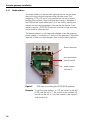
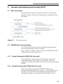
5.1 Basic functionality
The picture below gives an overview of the basic encoder and
gateway functions and how the functionality is conducted within
the device.
Figure 13
Basic functionality
5.2 PROFIBUS data transfer principle
The PROFIBUS-DP devices can be configured and parameters
can be set according to the user’s needs.
In this context it is useful to know that with PROFIBUS there are
different types of data transmission.
5.2.1
During Configuration (DDLM_Chk_Cfg mode)
The configuration function allows the DP-Master to send the
configuration data to the DP-device for checking. The main
purpose is to define the number of bytes used for Data_Exchange
function.
5.2.2
During Parameterization (DDLM_Set_Prm mode)
When the system is started, the PROFIBUS devices are
parameterized (DDLM_Set_Prm mode), i.e. the encoder class set
by means of the GSD file in the configuration tool) and the set
operating parameters are transferred to the respective slave.
31
Encoder and Gateway functionality, DPV0
5.2.3
Normal operation (DDLM_Data_Exchange mode)
In the normal mode (DDLM_Data_Exchange mode), data are
exchanged between master and slaves. The preset function can
be carried out only in this operating mode. The data exchange is
described in chapter 5.5.
5.3 Configuration, DPV0
The configuration of a DPV0 device is conducted by choosing
encoder class, i.e. setting the input/output data structure. The
configuration options are 16-bit, 32-bit or 32-bit + 16-bit
velocity input data, for explanation view chapter 4.1.
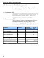
5.4 Parameterization, DPV0
The PROFIBUS-DPV0 device is parameterized by means of
the operating parameters. The values selected in the
configuration tool are saved in the DP master and are
transferred to the PROFIBUS-DP slave each time the network
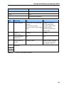
is started. The following table lists all available parameters:
Parameters
Data type
Parameter
octet number
Device
class
Code sequence
Bit
9
1
Class 2 functionality
Bit
9
2
Commissioning diagnostics
Bit
9
Optional
Scaling function control
Bit
9
2
Measuring units per revolution
Unsigned 32 bits
10-13
2
Total measuring range in
measuring units
Unsigned 32 bits
14-17
2
Manufacturer specific functions
Bit
26-28
Optional
Velocity control
2 bit
39
2.ext
Table 11
32
Operating parameters in DPV0
Encoder and Gateway functionality, DPV0
Octet
9
Bits
7-0
Data
2 -2
7
0
Operating parameters
Bits
Definition
=0
=1
0
Code sequence
Clockwise (CW) Increasing
position
values when rotated
clockwise (seen from flange
side)
Counter clockwise
(CCW) Increasing
position values when
rotated counter
clockwise (seen from
flange side)
1
Class 2
functionality
Disable
Enable
2
Commissioning
diagnostics
No
Yes
3
Scaling function
control
Disable scaling
Enable scaling. Scaling
parameters are taken
into octets 10 to 17.
4
Reserved
...
7
Table 12
Octet 9, Parameter definition
33
Encoder and Gateway functionality, DPV0
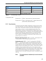
5.4.1
Code sequence
The code sequence defines whether the absolute position value
should increase during clockwise or counter clockwise rotation of
the encoder shaft seen fromflange side. The code sequence is by
default set to increase the absolute position value when the shaft
is turned clockwise (0).
Note:
5.4.2
The position value will be affected when the code
sequence is changed during operation. It might be
necessary to perform a preset after the code
sequence has been changed.
Class 2 functionality
This bit enables or disables class 2 functionality. The Class 2
functionality bit for PROFIBUS-DP devices is by default disabled
(0). This means that this control bit must be activated during
parameterization in order to support the class 2 functions.
Note:
5.4.3
If a class 1 device uses some optional class 2
functions, the class 2 control bit must be set.
Commissioning diagnostics
The commissioning diagnostics function makes enable the device
to perform internal diagnostic test of the encoder components
responsible for position detection during a standstill of the
encoder (i.e. light unit, photovoltaic cells etc.). In conjunction
with the position alarms, it enables thorough checking of
whether the position values provided by the absolute encoder
are correct. The commissioning diagnostics function is started
by the commissioning bit in the operating parameters. If an
error is found within the absolute encoder, this is indicated in
the diagnostic function by the commissioning diagnostics
alarm bit (see chapter 5.6.2).
The commissioning diagnostics function is an option. To find out
whether the device supports commissioning diagnostics, the
“operating status” should be read by the diagnostic function
and the commissioning diagnostics bit should be checked.
34
Encoder and Gateway functionality, DPV0
5.4.4
Scaling function control
The scaling function converts the encoder’s physical absolute
position value by means of software in order to change the
resolution of the encoder. Class 2 functionality must be enabled in
order to use the scaling function. The parameters “Measuring
units per revolution” and “Total measuring range in measuring
steps” are the scaling parameters set by the parameter function
in octet 10 to 17. Scaling is active only if the control bit for the
scaling function is set. When the scaling function control bit is set
to 0, the scaling function is disabled.
Singleturn encoders up to 31 bit and multiturn encoders up to
37 bits resolution are supported by the PROFIBUS gateway.
When using encoders with higher resolution than 31 bits, the
singleturn resolution of the encoder will automatically be reduced
as much as needed to fit into the 32 bit structure.
For example, if a 37 bit encoder with a 25 bit singleturn and 12 bit
multiturn resolution is used, the singleturn resolution will be
reduced from 25 to 19 bit, and the multiturn resolution will still be
12 bit. (19 bit singleturn+12 bit multiturn = 31 bit total resolution).
Note:
5.4.5
After downloading new scaling parameters the
Preset function must be used to set the encoder
starting point to absolute position 0 or to any
required starting position within the scaled
operating range.
Measuring units per revolution
The total measuring range is calculated by multiplying the
singleturn resolution with the number of distinguishable
revolutions.
The default settings for singleturn encoders are:
Measuring units per revolution= 8192 (213)
Total measuring range in measuring units= 8192 (213 x 20)
The default settings for 25 bit multiturn encoders are:
Measuring units per revolution= 8192 (213)
Total measuring range in measuring units= 33554432 (213 x 212)
35
Encoder and Gateway functionality, DPV0
Format of the scaling parameters:
Octet
10
11
12
13
Bits
31-24
23-16
15-8
7-0
Data
231-224
223-216
215-28
27-20
Measuring units per revolution
Table 13
Singleturn scaling parameters format
Octet
10
11
12
13
Bits
31-24
23-16
15-8
7-0
Data
231-224
223-216
215-28
27-20
Measuring units per revolution
Table 14
Multiturn scaling parameters format
The data format for both scaling parameters is 32 bits without
sign, with a value range from 20 to 231. The permissible value
range is limited by the resolution of the encoder. For a 25-bit
encoder with a singleturn resolution of 13 bits the permissible
value range for “Measuring units per revolution” is between 20
and 213 (8192) and for the “Total measuring range in measuring
steps” the permissible value range is between 20 and 225
(33554432). The scaling parameters are securely stored in the
PROFIBUS-DP master and are reloaded into the encoder at each
power-up. Both parameters are output data in 32-bit format.
Example of scaling and entry:
If the user wants to scale the encoder to a single turn resolution
of 4000 unique positions per revolution and a total number of turn
count equal to 3200 revolutions shall the configuration be as:
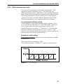
Measuring units per revolution = 4000 steps
Total measuring range in measuring units
= 4000 steps x 3200 revolutions
= 12800000
Entry in the master configuration software:
Measuring units per revolution = 4000
Total measuring range (steps) = 12800000
36
Encoder and Gateway functionality, DPV0
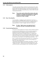
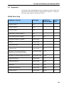
5.4.6
Total measuring range (units)
The total measuring range is defined by the parameter “Total
measuring range in measuring units.” The device has two
different operating modes, depending on the specified measuring
range. When the device receives a parameter message, it checks
the scaling parameters if a binary scaling can be used. If binary
scaling can be used, the device selects operating mode A (see
following explanation). If not, operating mode B is selected.
A. Cyclic operation (Binary scaling)
Cyclic operation is used when operating with 2x number of turns
(2, 4, 8, 16, 32, 64, 128, 256, 512, 1024, 2048. 4096.. number of
turns). If the desired total measuring range is equal to the
specified single turn resolution * 2x (where x<= 12) the encoder
operates in endless cyclic operation (0 - max - 0 -max..). If the
position value increases above the maximum value by rotating the
encoder shaft, the encoder continues from 0.
Example of a cyclic scaling:
Total measuring range = Measuring units per revolution x number
of revolutions
Measuring units per revolution = 1000
Total measuring range = 32000 (25 = number of revolution 32)
Figure 14
Cyclic scaling
37
Encoder and Gateway functionality, DPV0
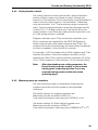
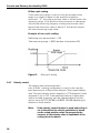
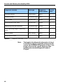
B. Non-cyclic scaling
If the measuring range is used to limit the encoder value
range to a value not equal to the specified singleturn
resolution * 2X, the output position value is limited within the
operating range. If the position value increases or decreases
outside the measuring range by rotating the encoder shaft
beyond the maximum value or below 0, the device outputs
the total measuring range value.
Example of non-cyclic scaling:
Measuring units per revolution = 100
Total measuring range = 5000 (number of revolutions 50)
Figure 15
5.4.7
Non-cyclic scaling
Velocity control
The velocity data can be accessed if
class 2 32-bit + velocity configuration is used. In this case the
input data consists of 32-position data plus 16-bit signed velocity
data. The input velocity value is negative in CCW direction if code
sequence is set to CW. If the measured velocity is higher then
what is possible to present with the selected velocity unit the
value is set to 0x7FFF (32768) or 0x8000 (-32768) depending on
direction of shaft rotation.
Note:
38
If the velocity control function is used and scaling is
set to the device the velocity calculation is based
on the scaled position value. Consequently the
accuracy of the velocity value is dependent of the
scaling set to the device.
Encoder and Gateway functionality, DPV0
5.4.8
Velocity calculation
The velocity calculations are made with a maximum of
19 bits resolution. If the resolution is higher than 219, the value
used for velocity calculations is automatically reduced to 219. For a
multiturn encoder with 212 multiturn resolution, the maximum
singleturn value will be 219 and the velocity will be calculated on
the same resolution as presented in the diagnostic structure. For
a singleturn encoder the resolution can be up to 31 bit, but the
velocity calculations will be made on maximum 19 bits. This
means that in the diagnostic structure, the value 231 can be
presented, but the resolution used for velocity calculations is not
presented if the singleturn resolution is higher than 219.
The parameter for velocity unit, octet 39 can be seen below:
Octet
39
Bits
7-0
Data
27-20
Velocity control
Bit
7
Table 15
6
5
4
3
2
1
0
Velocity unit
0
0
Steps/s
0
1
Steps/100 ms
1
0
Steps/10 ms
1
1
RPM (revolutions
per minute)
Octet 39, Velocity Control
In case of steps/s unit, an average is made over 200 ms, and the value is multiplied by 5.
39
Encoder and Gateway functionality, DPV0
5.5 Data transfer in normal operation (DDLM_Data_Exchange)
The DDLM_Data_Exchange mode is the normal status of the
device when operated. In this mode the position value is
transmitted from the device in a cyclic manner. Output data can
also be sent to the device i.e. preset commands.
5.5.1
Data exchange mode
The actual position value is transferred to the master as 32-bit
values (double word) or optional, the device supports
a position value length of 16-bit for singleturn encoder. The
position value is right-aligned in the data field.
DDLM_Data_Exchange mode
Standard configuration:
Octet
1
2
3
4
Bits
31-24
23-16
15-8
7-0
Data
231-224
223-216
215-28
27-20
Data_Exchange -32 bits
Table 16
Data exchange -32-bits
Configuration data:
Device class 1: D1hex 2 input data words, data consistency
Device class 2: F1hex 2 input data words, 2 output data words for
preset value, data consistency
40
Encoder and Gateway functionality, DPV0
Octet
1
2
Bits
15-8
7-0
Data
215-28
27-20
Data_Exchange -16 bits
Table 17
Data exchange -16 bits
Configuration data:
Device class 1: D0hex 1 input data word, data consistency
Device class 2: F0hex 1 input data word, 1 output data word for
preset value, data consistency
5.5.2
Preset function
The preset function enables adaptation of the position value
from the encoder to a known mechanical reference point of
the system. The preset function sets the actual position of
the encoder to zero or to the selected preset value. The
preset value is written to the encoder as output data in the
Data_Exchange function. If scaling is used the preset function
shall be used after the scaling function, to ensure that the
preset value is entered in the current measuring unit. The
most significant bit (MSB) of the preset value controls the
preset function as follows:
Normal operating mode: MSB = 0 (bit 31, optionally bit 15)
The encoder will not change the preset value.
Activated mode: MSB = 1 (bit 31, optionally bit 15) With
MSB = 1, the encoder accepts the transferred value (bits 0 –
30) as a preset value in binary code. The encoder reads the
current position value and calculates an offset value from the
preset value and the read position value. The position value is
shifted by the calculated offset value. If the input position
value equals the preset value, the preset mode is terminated
and the MSB can be set to 0 by the master. The offset value
can be read with the diagnostic function and is securely
stored in case of a power interruption and is reloaded at each
start-up.
Note:
The preset function should only be used at encoder
standstill.
41
Encoder and Gateway functionality, DPV0
Preset value format (2 words, 32 bits)
Octet
1
Bits
31
Data
Table 18
2
3
4
30-24
23-16
15-8
7-0
0/1
230-224
223-216
215-28
27-20
Preset control
bit
Preset value – Max. 31 bits
Preset value, 32-bit format
Preset value format (1 words, 16 bits)
Octet
1
Bits
15
14-8
7-0
Data
0/1
214-28
27-20
Preset control
bit
Preset value – Max.15 bits
Table 19
42
2
Preset value, 16-bit format
Encoder and Gateway functionality, DPV0
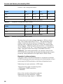
5.6 Diagnostics
The diagnostic information contains diagnostic data which are
defined in the PROFIBUS-DP specification (octets 1 to 6) but
also encoder specific diagnostic data:
DDLM_Slave_Diag
Diagnostic function
Data type
Diagnostic
Octet number
Device
class
Station status 1
Bits
1
1
Station status 2
Bits
2
1
Station status 3
Bits
3
1
Diagnostics master address
Bits
4
1
PNO identification number
Bits
5-6
1
Extended diagnostic header
Octet string
7
1
Alarms
Octet string
8
1
Operating status
Octet string
9
1
Encoder type
Octet string
10
1
Singleturn resolution(encoder)
Measuring unit (linear encoder)
32 without sign
11-14
1
Number of distinguishable revolutions
16 without sign
15-16
1
Additional alarms
Octet string
17
2
Supported alarms
Octet string
18-19
2
Warnings
Octet string
20-21
2
Supported warnings
Octet string
22-23
2
Profile version
Octet string
24-25
2
43
Encoder and Gateway functionality, DPV0
Diagnostic function
Data type
Diagnostic
Octet number
Device
class
Software version
Octet string
26-27
2
Operating time
32 without sign
28-31
2
Offset value
32 with sign
32-35
2
Manufacturer offset value
32 with sign
36-39
2
Measuring units per revolution
32 without sign
40-43
2
Total measuring range in measuring
units
32 without sign
44-47
2
Serial number
ASCII string
48-57
2
58-61
2
Reserved for future
Table 20
Diagnostic message, DPV0
Note:
44
The length of the diagnostic information of class 1
is limited to 16 bytes, compatible with previos DP
version. For PROFIBUS-DP encoders of class 2, the
length of the encoder specific diagnostic data
including the extended diagnostic header is
57 bytes.
Encoder and Gateway functionality, DPV0
5.6.1
Diagnostic Header
The header byte specifies the length of the encoder diagnostics
including the header byte. The format of the transmission length
is hexadecimal. For the PROFIBUS-DP encoder of class 1 the
length of the encoder-specific diagnostic data is 10 bytes (0Ahex).
DDLM_Slave_Diag
Octet
7
Alarms
7
6
5-0
Data
0
0
xxh
Set to 00
Length incl. header
Extended diagnosis
Table 21
5.6.2
Diagnostic header
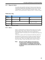
Alarms
Alarm is generated by the device when failure occurs which
effects the position value. Octet 8 in the diagnostic function
(DDLM_Slave_Diag) indicates the status of the alarms.
Additional alarms for device class 2 are addedin the diagnostic
octet 17.
If an alarm is given, the Ext_Diag bit and the Stat_Diag bit in
the diagnostic function are set to high and remain high until
the alarm is cleared and the encoder can provide a correct
position value. Alarms are cleared when the functionality is
within the specifi- cation and the position value is correct.
Note:
Not every encoder supports every alarm. For
encoders of class 2 the diagnostic information
“supported alarms” (see Chapter 5.6.8) makes it
possible to find out which individual alarm bits are
supported.
45
Encoder and Gateway functionality, DPV0
DDLM_Slave_Diag
Octet
8
Bits
7-0
Alarms
Bits
Definition
=0
=1
0
Position error
No
Yes
1
Voltage supply error
No
Yes
2
Current is too high
No
Yes
3
Commissioning diagnostics
OK
Error
4
Memory error
No
Yes
5-7
Currently not assign
Table 22
46
Alarms
Encoder and Gateway functionality, DPV0
5.6.3
Operating Status
Octet 9 in the diagnostic function provides information
about encoder-specific parameters. A class 2 encoder
sets the functionality bit for class 2 commands in order to
show the DP master that all class 2 commands are
supported. The DP master must activate the class 2
functionality bit in the parameter message (DDLM_Set_Prm)
to enable the use of class 2 functions. The status bit of
the scaling function is set when the scaling function is
activated and the resolution of the encoder is calculated
by means of the scaling parameters.
DDLM_Slave_Diag
Octet
9
Bits
7-0
Operating status
Bits
Definition
=0
=1
0
Code sequence
Increasing position
values for clockwise
revolutions (Seen from
flange side)
Increasing position
values for counter
clockwise revolutions
(Seen from flange side)
1
Class 2
functionality
No, not supported
Yes
2
Commissioning
diagnostics
No, not supported
Yes
3
Scaling function
status
Scaling disabled
Scaling enabled
4-7
Currently not assigned
Table 23
Operating status
47
Encoder and Gateway functionality, DPV0
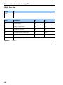
5.6.4
Encoder type
The type of encoder can be read in octet 10 of the diagnostic
function. The type of encoder is defined in hex-code in the range
from 0 to FF.
DDLM_Slave_Diag
Octet
10
Bits
0-FF
Encoder type
Bits
Definition
00
Absolute singleturn encoder
01
Absolute multiturn encoder
02
Absolute singleturn encoder with electronic revolution counter
03
Incremental rotary encoder
04
Incremental rotary encoder with battery buffer
05
Incremental linear encoder
06
Incremental linear encoder with battery buffer
07
Absolute linear encoder
08
Absolute linear encoder with periodic coding
09-FF
Currently not assigned
Table 24
48
Diagnostic, encoder
Encoder and Gateway functionality, DPV0
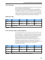
5.6.5
Singleturn resolution or measuring step
The singleturn resolution in the diagnostic function has different
meanings depending on the type of encoder.
For rotary or angle encoders, the diagnostic octets 11 to 14
indicate the physical resolution in number of measuring steps per
revolution which is transferred for the absolute singleturn position
value. The maximum singleturn resolution is 2 . For linear
encoders the measuring steps is presented with respect to the
resolution of the linear encoder, i.e. each increment of the
measuring step is equal the actual resolution for the linear
encoder in use. Typical values for the linear resolution are
1µm - 40 µm.
31
DDLM_Slave_Diag
Octet
11
12
13
14
Bits
31-24
23-16
15-8
7-0
Data
231-224
223-216
215-28
27-20
Singleturn resolution
Table 25
5.6.6
Diagnostic, singleturn resolution
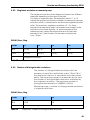
Number of distinguishable revolutions
The number of distinguishable revolutions that the
encoder can transfer is defined by octets 15 and 16 of
the diagnostic function. In accordance with the formula
below, the measuring range for an encoder results from
the number of distinguishable revolutions multiplied by
the singleturn resolution. The maximum number of
distinguishable revolutions is 65536-1(16 bits).
Measuring range = number of distinguishable revolutions
x singleturn resolution
DDLM_Slave_Diag
Octet
15
16
Bits
15-8
7-0
Number of distinguishable revolutions
Table 26
Diagnostics, number of distinguishable revolutions
49
Encoder and Gateway functionality, DPV0
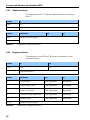
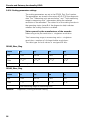
5.6.7
Additional alarms
The diagnostic octet 17 indicates additional alarms for device
class 2.
Octet
17
Bits
7-0
Additional alarms
Octet
Definition
Bits
Currently not assigned
=0
=1
0..7
Table 27
5.6.8
Diagnostics, additional alarms
Supported alarms
The diagnostics octet 18 and 19 contain information on the
supported alarms.
Octet
18
19
Bits
15-8
7-0
Supported alarms
Octet
Definition
=0
=1
0
Position error
Not supported
Supported
1
Voltage supply error
Not supported
Supported
2
Current is too high
Not supported
Supported
3
Commissioning diagnostics
Not supported
Supported
4
Memory error
Not supported
Supported
5..15
Currently not assigned
Table 28
50
Diagnostics, supported alarms
Encoder and Gateway functionality, DPV0
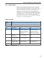
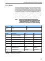
5.6.9
Warnings
Warnings indicate that tolerances for certain internal parameters
of the device have been exceeded. Contrary to alarms, no faulty
position values are expected in case of warnings. Octets 20 and
21 of the diagnostic function indicate the status of the warnings.
If a warning is set, the Ext_Diag bit in the diagnostic function is
logically set to 1 until the warning is cleared. All warnings are
deleted when the diagnostic message of the device has been
read. However, if the tolerances are still exceeded, the warning is
activated again. The warning “Maximum operating time exceeded”
(bit 4) is not activated before the system is switched on again.
Note:
Not every encoder supports every warning.
Please refer to the diagnostic information under
“Supported Warnings”, see chapter 5.6.10, for
information on the support of specific warnings.
Octet
20
21
Bits
15-8
7-0
Warnings
Octet
Definition
=0
=1
0
Frequency exceeded
No
Yes
1
Temperature exceeded
No
Yes
2
Light control reserve
Not reached
Reached
3
CPU monitoring status
OK
Reset
4
Maximum operating time
exceeded
No
Yes
5
Battery charging
OK
Too low
6
Reference point
Reached
Not reached
7..15
Currently not assigned
Table 29
Diagnostics, warnings
51
Encoder and Gateway functionality, DPV0
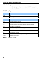
5.6.10 Supported warnings
The diagnostics octet 22 and 23 contain information about
supported warnings.
Octet
22
23
Bits
15-8
7-0
Supported Warnings
Octet
Definition
=0
=1
0
Frequency warning
Not supported
Supported
1
Temperature warning
Not supported
Supported
2
Light control reserve warning
Not supported
Supported
3
CPU monitoring status warning
Not supported
Supported
4
Maximum operating time
exceeded warning
Not supported
Supported
5
Battery charging warning
Not supported
Supported
6
Reference point warning
Not supported
Supported
7..15
Currently not assigned
Table 30
52
Diagnostics, supported warnings
Encoder and Gateway functionality, DPV0
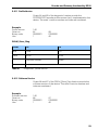
5.6.11 Profile Version
Octets 24 and 25 of the diagnostic function provide the
PROFIBUS-DP encoder profile version that is implemented in the
device. The octet’s revision number and index are combined.
Example:
Profile version
Octet no.
Binary code.
Hex.
1.40
24
00000001
1
25
01000000
40
DDLM_Slave_Diag
Octet
24
25
Bits
15-8
7-0
Data
27-20
27-20
Revision number
Index
Profile Version
Table 31
Diagnostics, profile version
5.6.12 Software Version
Octets 26 and 27 of the DDLM_Slave_Diag function provide the
software version of the device. The octet’s revision number and
index are combined.
Example:
Software version
Octet no.
Binary code.
Hex.
1.40
26
00000001
1
27
01000000
40
53
Encoder and Gateway functionality, DPV0
DDLM_Slave_Diag
Octet
26
27
Bits
15-8
7-0
Data
27-20
27-20
Revision number
Index
Software Version
Table 32
Diagnostics, software version
5.6.13 Operating time
The operating time monitor stores the operating time for the
device in operating hours. The operating time is saved every six
minutes in the non-volatile memory in the device. This happens
as long as the device is under power. The operating time is
displayed as a 32-bit value without sign in 0.1 h by the
DDLM_Slave_Diag function.If the operating time function is
not supported by the device, it is set to the maximum value
(FFFF FFFF hex).
DDLM_Slave_Diag
Octet
28
29
30
31
Bits
31-24
23-16
15-8
7-0
Data
231-224
223-216
215-28
27-20
Operating time
Table 33
54
Diagnostic, operating time
Encoder and Gateway functionality, DPV0
5.6.14 Offset value
The offset value is calculated by the preset function and shifts the
position value by the calculated value.
The offset value is stored in the device and can be provided by
the diagnostic octets 32 to 35. The data type for the offset value
is a 32-bit binary value with sign, whereby the offset value range
is equal to the measuring range of the device. The preset function
is used after the scaling function. This means that the offset value
is indicated according to the scaled resolution of the device.
DDLM_Slave_Diag
Octet
32
33
34
35
Bits
31-24
23-16
15-8
7-0
Data
231-224
223-216
215-28
27-20
Offset value
Table 34
Diagnostics, offset value
5.6.15 Offset value of the encoder manufacturer
The manufacturer offset value indicates the encoder offset set by
the manufacturer. This value gives information on the shift of the
position zero point in number of positions from the physical zero
point of the encoder. The data type for the offset value is a 32-bit
binary value with sign. The value range corresponds to the
measuring range of the encoder. The offset value of the
manufacturer of the encoder is indicated in the number of units
according to the basic resolution of the encoder. The value is
stored in write-protected memory, which can be changed only by
the encoder manufacturer. This value has practically no
importance for the user.
Octet
36
37
38
39
Bits
31-24
23-16
15-8
7-0
Data
231-224
223-216
215-28
27-20
Offset value of the encoder manufacturer
Table 35
Diagnostics, offset value of the encoder manufacturer
55
Encoder and Gateway functionality, DPV0
5.6.16 Scaling parameters settings
The scaling parameters are set in the DDLM_Set_Prm function.
The parameters are stored in the octets 40 to 47 of the diagnostic
data. The “Measuring units per revolution” and “Total measuring
range in measuring units” parameters define the selected
resolution of the encoders. The status bit of the scaling function in
the operating status (octet 9 of the diagnostic data) indicates
whether the scaling function is enabled.
Values preset by the manufacturer of the encoder:
Measuring units per revolution = singleturn resolution.
Total measuring range in measuring units = singleturn
resolution x number of distinguishable revolutions.
The data type for both values is unsigned 32 bits.
DDLM_Slave_Diag
Octet
40
41
42
43
Bits
31-24
23-16
15-8
7-0
Data
231-224
223-216
215-28
27-20
Measuring units per revolution
DDLM_Slave_Diag
Octet
44
45
46
47
Bits
31-24
23-16
15-8
7-0
Data
231-224
223-216
215-28
27-20
Total measuring range in measuring units
Table 36
56
Diagnostics, scaling parameter setting
Encoder and Gateway functionality, DPV0
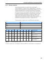
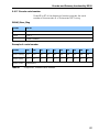
5.6.17 Encoder serial number
Octet 48 to 57 of the diagnostic function provides the serial
number of the encoder as a 10-character ASCII string.
DDLM_Slave_Diag
Octet
48-57
Bits
79-0
Data
ASCII
Serial number
Example of a serial number
Octet
48
49
50
51
52
53
54
55
56
57
ASCII string
30
30
30
35
39
46
38
44
45
35
Serial (hex)
0
0
0
5
9
F
8
D
E
5
Serial (Dec)
94342629
Table 37
Diagnsotics, encoder serial number
57
Encoder commissioning example, DPV0
6
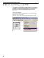
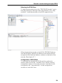
Encoder commissioning example, DPV0
This example uses a Siemens master software. The example is
intended to illustrate the commissioning of a PROFIBUS-DPV0
encoder with a 25 bit absolute rotary encoder and velocity
information.
Copying the GSD file
First, copy the GSD file and bitmap file into the corresponding
directory in the configuration
software,...\GSD. Then install the GSD file into your system.
58
Encoder commissioning example, DPV0
Selecting the DPV0 Slave
To select the encoder click on the “PROFIBUS Encoder” icon in
the map structure on the right side of the window. Use “dragand-drop” to add the encoder on the BUS, upper left view.
When dropping the encoder on the BUS a PROFIBUS address
must be assigned, naturally this address must be the same as
assigned on the hardware address switches on the back of the
encoder. See chapter 3.1.1.
Configuration of DPV0 Slave
To configure the encoder for 25-bit position value plus
velocity data choose the “Encoder Class 2 32-bit velocity”
configuration option in the map structure. Add the chosen
configuration by “drag-and-drop” to the configuration
window in lower left view.
59
Encoder commissioning example, DPV0
Assigning parameters to the DPV0 slave
By “double-clicking” on the configuration row in the
configuration view the parameterization view will be opened.
Add or change the data in the “value” field to the desired
parameter values. Chapter 5,4 describes the functionality and
possibility of each parameter. Then save and compile the setting
by clicking Save and compile on the Station tab.
60
Revision history
7
Revision history
Revision
Date
changes
Rev. 1.0
2014-07-01
First release
Table 38
Revision history
61
DR. JOHANNES HEIDENHAIN GmbH
Dr.-Johannes-Heidenhain-Straße 5
83301 Traunreut, Germany
{ +49 8669 31-0
| +49 8669 5061
E-mail: [email protected]
www.heidenhain.de
1111895-20 · Ver00 · 7/2014 · PDF