1
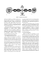
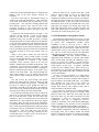
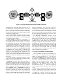
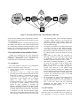
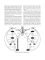
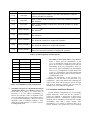
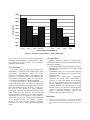
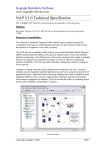
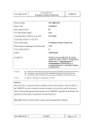
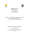
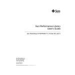
An Unavailability Analysis of Firewall Sandwich Configurations
Steve Goddard
Computer Science & Engineering
University of Nebraska – Lincoln
Lincoln, NE 68588-0115
[email protected]
Abstract
Firewalls form the first line of defense in securing
internal networks from the Internet. A Firewall only
provides security if all traffic into and out of an internal
network passes through the firewall. However, a single
firewall through which all network traffic must flow
represents a single point of failure. If the firewall is
down, all access is lost. A common solution to this
problem is to use firewall sandwiches, comprising
multiple firewall processors running in parallel.
A firewall sandwich system needs load-balancing
processes executing on separate processors to manage
the flow of packets through the firewall processors. The
number of redundant load balancing processors and their
redundancy management policies have a major impact on
system unavailability. We present a model to analyze the
steady-state unavailability of firewall sandwiches and
compare the unavailability of various load-balancing
configurations. The results show that, using
representative non-proprietary values for system
parameters, redundancy management policies are at least
as important as the number of redundant processing
nodes.
1. Introduction
The importance of networking and the Internet have
grown dramatically over the last five years.
It is
commonly accepted that businesses not only have access
to the Internet for their employees, but that they have a
“presence on the net” for customers to shop and purchase
items via the Internet. Over the past five years the terms
e-commerce and business-to-business (or B2B) commerce
have moved from arcane terminology to pop vocabulary.
Networks have grown from a convenient internal
productivity tool to a necessary component of almost all
businesses. Due to businesses’ increased reliance on the
Internet and the amount of revenue that is lost when their
connection to the Internet is down, a company’s network
and its internet connection should be viewed as a high
assurance, high consequence system.
Roger Kieckhafer
Yuping Zhang
Electrical & Computer Engineering
Michigan Technological University
Houghton, MI 49931-1295
{rmkieckh,yuping}@mtu.edu
This paradigm shift in business, which requires a
portal to the Internet, has created an open-door to
computer systems and valuable information that was
never meant to be available to the public. Thus,
companies are faced with a paradox: they must protect
their confidential and high consequence systems while
maintaining public access to portions of their network.
To solve this paradox, most companies use a firewall to
protect their internal networks from unwanted intrusions
while still allowing public access to select servers and a
secure portal through which employees can reach the
Internet from internal networks.
A firewall inspects packets flowing across network
boundaries and allows or denies access to
internal/external servers on the basis of defined policies.
It thus forms the first line of defense in securing internal
networks from the Internet. However, a firewall only
provides security if all traffic into and out of an internal
network passes through the firewall. The problem is that
a single firewall, through which all network traffic must
flow, represents a single point of failure; if the firewall is
down, all access is lost. The use of a single firewall may
also create a throughput bottleneck.
Firewall sandwiches are commonly used to remove the
single point of failure as well as the potential bottleneck
of a single firewall. A firewall sandwich consists of two
or more firewalls configured in parallel with load
balancing entities (nodes) on either side of the firewalls,
as shown in Figure 1. The firewall load balancing (FLB)
nodes on both sides of the network boundary ensure that
connection oriented TCP/IP traffic passes through the
same firewall in both directions. Since connection
requests may originate and terminate in either internal or
external networks (shown as Private Net and Public Net
in Figure 1), the two FLBs perform symmetric operations
in the firewall sandwich.1
The firewall sandwich removes the firewall as the
single point of failure. However, it creates two new
points of failure: the load balancing nodes on either side
of the firewalls. Thus, the simple solution developed to
1
When the firewalls perform network address translation
(NAT), the FLB operations are not entirely symmetric.
Public
Net
/$1
6ZLWFK
)/%
/$1
6ZLWFK
)/%
Private
Net
)LUHZDOO6HW
Figure 1: Typical firewall sandwich.
improve the availability of a company’s Internet access
may actually reduce availability! To overcome this new
problem, vendors offer a variety of redundant FLB
configurations. Vendors are happy to sell four (or more)
FLB nodes to build a highly available system; but how
many firewalls and FLBs are needed to achieve high
availability? To the best of our knowledge, there has
been no research conducted to investigate this and related
cost/benefit analysis questions.
In this work, a model to evaluate the unavailability of
firewall sandwiches is presented, and used to compare the
unavailability
of
common
firewall
sandwich
configurations. The rest of this paper is organized as
follows. Section 2 discusses background information and
related work. Section 3 presents our firewall sandwich
unavailability model. Section 4 compares the results of
the unavailability evaluations. Section 5 presents
conclusions and directions for future research.
2. Background and Related Work
The technology behind FLB devices is based on
extensive research and development in the area of
transparent network server clustering. Server clustering
technologies are broadly classified as: OSI layer four
switching with layer two packet forwarding (L4/2); OSI
layer four switching with layer three packet forwarding
(L4/3); and OSI layer seven (L7) switching with either
layer two packet forwarding (L7/2) or layer three packet
forwarding (L7/3) clustering. These terms refer to the
techniques by which the servers in the cluster are tied
together. A tutorial overview of these clustering
technologies is presented in [9].
From a clustering point of view, balancing network
connections over a set of firewalls (FWs) is similar to
balancing connection requests over a set of network
servers in an L4/2 server cluster. That is, all network
traffic passing through the FW boundary must pass
through an FLB before reaching the FWs; the FLB
appears as a network gateway to servers and/or routers.
The primary difference between server clustering and FW
sandwiching is that the FW is not the final destination for
network traffic. From a network packet’s perspective
each FLB node and its assigned FW node appear to be
hops in the network.
To the best of our knowledge, there are no research
publications that describe the implementation of FW
sandwiches. However, [3] provides a detailed description
of L4/2 clustering techniques for network servers. Section
2.1 provides a high-level description of a typical FW
sandwich implementation.
Section 2.2 describes
configurations and various FLB redundancy management
policies employed to achieve FLB fault-tolerance.
Section 2.3 provides background information on system
unavailability modeling.
2.1. Firewall Sandwiches
Almost all research and development on FW
sandwiches has been done by vendors who also provide
server load balancing and clustering devices. Prominent
vendors include Cisco, F5 Networks, Alteon (now owned
by Nortel), Foundry, Ipivot/Intel, IBM, Resonate, and
CoyotePoint. The FLB devices sold by these companies
range from products that combine switching, routing, and
FW load balancing into one hardware device to products
that are based on the BSD operating system and PC-like
hardware. In contrast to these products, the University of
Nebraska-Lincoln (UNL) has developed an entirely
application space FLB solution, whose technology is
being licensed to Flextel S.p.A. The UNL FLB requires
no modifications to the operating system or device drivers
and is considered a software-based balancer. Hardware
devices, such as Foundry’s ServerIron FLB switch, will
always outperform software-based balancers, but offer
much less operational flexibility. While load-balancing
switches provide unparalleled performance, our
experience indicates that software-based balancers can
meet the needs of all but the busiest sites [3]. Most sites
saturate their network bandwidth before a software-based
balancer, such as the UNL solution, becomes the
bottleneck.
The focus of this paper is unavailability analysis of
common FW sandwich configurations. Thus, the details
of the UNL FLB solution and its performance are not
presented here. Our experience building fault-tolerant
FLB solutions, however, does form the basis of the
processing described in this section and the FLB
redundancy management policies described in the next
section.
Consider the FW sandwich depicted in Figure 1. For
simplicity, assume Ethernet is used for the physical
network; the FWs do not perform network address
translation (NAT) [10]; and that all traffic is TCP/IP.
Assuming all traffic is TCP/IP simplifies the presentation
of the processing performed by FW sandwiches but does
not change the availability analysis presented. Under the
stated assumptions, the processing performed by the FLB
nodes is symmetric with respect to the flow of traffic from
the public network to the private network (and vice
versa).
When a SYN packet reaches the FLB from the
network (indicating a new TCP/IP session), the FLB
selects a FW through which the session traffic will flow.
Common algorithms for selecting a FW include
predefined (static) selection based on IP and port
numbers, Round Robin, Weighted Round Robin, Least
Connections, and Least-Packet Throughput. The FLB
forwards the packet to the selected FW by changing the
Ethernet destination MAC address of the packet to the
address of the selected FW. The FLB then changes the
source MAC address to its own address and puts the
packet onto the subnet connecting the FLB to the set of
FWs.
The FW receives the SYN message and decides
whether the packet (and the session) is allowed to pass
based on its predefined security policies. Assuming that
the packet is allowed to pass through the FW, it is
forwarded to the FLB on the other side of the sandwich.
This is achieved by identifying the FLB nodes as network
gateways for the subnets they share with the FWs.
For connection-oriented protocols, such as TCP/IP, all
packets for a given session must be forwarded to the same
FW (in both directions), unless the FWs share state
information. Here we assume the FWs do not share state
information since most commercial FWs do not support
this feature. When the SYN packet passes through the
second FLB, the FLB recognizes it as having come from a
FW, records the FW through which the packet passed and
forwards the packet to its destination or to its next hop in
the network. (Note that when static FW selection
algorithms are used, the processing performed by the
second FLB nodes is reduced; in fact, the node may be
bypassed completely in some cases.)
When the FLB receives a packet other than a SYN
packet, it checks whether it is part of an existing TCP
session. This is often done using the source and
destination IP addresses and the respective port numbers.
Assuming the packet belongs to an existing TCP session,
the FLB forwards it to the correct FW. The FW then
forwards the packet to the second FLB and so on. If the
packet does not belong to an existing TCP session, the
FLB either discards the packet, discards the packet and
replies with a RST packet, or forwards the packet to one
of the FWs for it to decide the packet’s fate.
2.2. FLB Redundancy Management Policies
The simple FW sandwich depicted in Figure 1 is able
to tolerate the benign failure of any two of the three FWs.
In general, such configurations maintain system
availability as long as any one of the n FWs is
operational. The loss of FWs may result in performance
degradation, but not system failure—unless all n FWs fail.
System failure occurs if either FLB fails or if all n FWs
fail. The rest of this section presents FLB redundancy
management policies that improve system availability.
Primary/Standby. The most common method of
improving system availability is to provide a hot standby
spare for each FLB, following the traditional primarybackup (or primary-copy) model [1] of fault tolerance.
Figure 2 depicts such a system. (For simplicity, we ignore
switch failures in this work. In practice, redundant
switches are also commonly used.) Most vendors use a
serial interface for out-of-band communications between
the primary and standby FLB nodes to maintain state and
to detect FLB failures.
An active replication approach [7] is employed by
some vendors to maintain state in the standby node;
multicast switches are used to send the same messages to
both the primary and standby FLB nodes. The standby
FLB maintains the same state as the primary by
processing the same packets in the same order. The
standby FLB, however, only outputs packets when it
detects the failure of the primary FLB.
Cisco supports a variation of the Primary/Standby
configuration in which the primary and standby nodes
share the active load. When one of the nodes fails, the
other node takes over the entire processing load. This
configuration is called an active-active redundancy
configuration. This type of configuration, however,
depends on extensions to the Virtual Router Redundancy
Protocol (VRRP) [5] and provides no more availability
than the more common Primary/Standby configuration.
The UNL application-space FLB solution supports the
Primary/Standby configuration with active replication in
the standby node, but it requires neither out-of-band
interface connections between the primary and standby
nodes nor multicast switches. In the Primary/Standby
Public
Net
)/%
/$1
6ZLWFK
/$1
6ZLWFK
)/%
6%
)/%
Private
Net
)/%
6%
)LUHZDOO6HW
Figure 2: Firewall sandwich with Primary/Standby FLB nodes.
configuration, the UNL FLB solution places the NIC of
the standby FLB in promiscuous mode to receive and
process a copy of all packets destined for the primary
FLB. A lightweight token protocol, called TokenBeat [8],
is used to detect the failure of the primary FLB and signal
activation of the standby FLB.
The Primary/Standby configuration encounters system
failure if either primary FLB and its respective standby
are both down or if all n FWs fail. (Note, once again, that
we are ignoring switch failures.)
Shared Standby. An alternative configuration is to
have a single standby FLB that is capable of taking over
for either primary FLB, as shown in Figure 3. To the best
of our knowledge, only the UNL FLB solution is capable
of supporting this configuration. The advantage of this
configuration is that one less standby FLB is needed to
achieve nearly the same level of availability. As long as
the FWs do not perform NAT, no additional processing
is required of the single standby to maintain state
consistency with both primaries than either dedicated
standby does in the primary/standby configuration. This
is because the shared standby only needs to process
packets from the private and public network interfaces to
maintain the same state information as the two primary
FLB nodes.
The shared standby configuration encounters system
failure if two of the three FLB nodes (counting the shared
standby) are down or if all n FWs fail.
Dual/Single. The UNL FLB solution is capable of
supporting a third high-availability configuration in which
there are no standby FLB nodes, but either primary FLB
can take over for the other in case of a FLB node failure.
In this configuration, the healthy UNL FLB node switches
from dual-FLB mode to single-FLB mode when it
detects a failure of the other node. In the default dualFLB mode, each FLB node functions like a normal FLB
node in a firewall sandwich. In the single-FLB mode,
however, a single FLB node performs the sandwiching
operations that two FLB nodes normally perform. From a
physical configuration view, both FLB nodes are
configured just as the shared standby FLB is in Figure 3.
In one sense, the dual/single configuration is a variation
of the ArrowPoint’s active-active configuration in that
there are no idle standby nodes. The difference is that in
the UNL dual/single configuration the two active nodes
are on “opposite sides of the firewall.”
The dual/single configuration encounters system
failure if both FLB nodes fail or if all n FWs fail. Note
that the loss of one FLB node may result in a degradation
of performance, but not in system failure. System
availability can be further improved by combining the
dual/single configuration with a shared standby. In such a
configuration, the first FLB node failure would result in
the shared standby taking over for the failed primary FLB
node with no degradation of performance. A second FLB
failure results in the last healthy FLB node switching
from dual-FLB mode to single-FLB mode (with a
possible degradation of performance).
2.3. System Unavailability Analysis Method
System Availability (A) tends to be a probability very
close to unity (i.e. a decimal with a large number of
leading “9”s). Thus Unavailability (U = 1− A) tends to be
more useful both numerically and semantically. There are
two measures of unavailability of interest: transient and
steady state. Transient unavailability is the probability
that the system is unavailable at time t, and is most
applicable for short lifetime systems. Steady state
unavailability is the probability that the system is
unavailable in the limit as t → ∞, and is more appropriate
for systems whose lifetimes span many failure and repair
cycles.
For this study, transient unavailability is not very
revealing. Assuming the system is fully operational at
start-up, the initial transient unavailability is zero. Then,
it asymptotically converges toward the steady state
unavailability value. The difference between transient and
Public
Net
)/%
/$1
6ZLWFK
/$1
6ZLWFK
)/%
Private
Net
)/%
6%
Figure 3: Firewall sandwich with a shared standby FLB node.
steady state unavailability decays exponentially with time.
Thus, analyses presented in this work are limited to steady
state unavailability.
To model unavailability, a Generalized Stochastic Petri
Net (GSPN) was drawn for each system architecture and
its corresponding redundancy management policies. The
GSPNs were evaluated using the commercially available
Stochastic Petri Net Package (SPNP) Ver. 6.0 [11].
3.
3. Firewall Sandwich Unavailability Models
GSPNs were developed for all of the architectures
defined in section 2. In addition, a few more variations in
redundancy
management
were
introduced
for
completeness and to yield baseline unavailabilities.
4.
5.
3.1. Assumptions
The system models are based on a set of assumptions
relatively common to systems of this type:
1. System dynamics include node faults, node reboot,
and node repair.
2. All faults are benign, i.e. a node fails without
generating undetectably erroneous data, and in such a
manner that its failure is “immediately self-evident”
to the rest of the system [2]. A more practical
interpretation is that diagnosis time is negligible
relative to other events in the system.
The benign fault mode is a very common assumption
in this type of system, primarily because of the
amount of effort expended to encourage that
behavior. In addition to Built-In Test (BIT), firewall
sandwich configurations also use detection messages
to identify faulty firewall or FLB nodes. The absence
or corruption of a fault detection message triggers
fault recovery actions that shut down the faulty node.
This approach to fault detection and recovery causes
6.
even non-benign faults, such as message corruption,
to appear benign. Moreover, the protocols for
client/server message traffic passing through the
firewall sandwich are designed to detect and recover
from corrupted messages.
The majority of all faults are soft faults, which can be
corrected by rebooting the node. While the majority
of soft faults are software bugs, transient hardware
faults can also exhibit the same behavior (in practice,
the software usually receives the blame for all soft
faults).
Hard faults are those faults not correctable by
rebooting. Correction of a hard fault requires repair
or replacement of the faulty node, which can
typically be performed while the system is on-line.
Node faults are mutually independent, i.e., a fault in
one node does not induce a fault in another node.
While this assumption is easily validated for
hardware faults, it is less certain for “generic”
software bugs. However, in the systems being
modeled, the software executing in a standby node
exercises different execution paths from active nodes
and from other standby nodes. It is thus unlikely that
a generic bug will strike all copies of the FLB
software at the same instant.
The node failure rate, repair rate and reboot rate are
all exponentially distributed. This assumption is
generally valid for failure rates. For repair and reboot
rates, it has been shown that the exponential
assumption has little impact on the system
dependability modeling results [4].
3.2. GSPN Models
Given the independence assumption above, the set of
FLB nodes and the set of FW nodes can be modeled as
two independent K-of-N:good systems (abbreviated
herein as K/N:g). In a K/N:g system, there are N initial
nodes; the system can function as long as any K nodes
remain non-faulty. Specifically, we define Nf and Nb as
the initial numbers of FW and FLB nodes, respectively.
We similarly define Kf and Kb as the minimum required
number of non-faulty FW and FLB nodes, respectively.
With one exception, all systems were modeled using
the dual K/N:g availability mode shown in Figure 4. This
model contains two identical “wings”, one for the FW
K/N:g model, and one for the FLB K/N:g model. The
boldfaced subnet in the center is the union of the
Unavailability of the two wings.
Since each wing of the GSPN model is functionally
and structurally identical, we will describe only the left
wing, representing the FWs. The model starts with Nf
tokens in place FW_up (in the upper left-hand corner),
representing Nf non-faulty FW nodes. Tokens are
removed from FW_up by faults, represented by the timed
transition flt_FW. Following node failure, rebooting is
attempted by timed transition rbt_FW. If the fault was soft
(with probability C), then reboot is successful and a token
is restored to place FW_up by transition rbt_suc_FW.
However, there is a (1-C) probability that the fault was
hard, in which case rebooting fails to restore the node to
operation. In this case, a token is put in place
FW_need_rep by transition rbt_fail_FW. Finally, node
repair is implemented by timed transition rep_FW, which
restores a token in place FW_up when repair is
completed.
The central subnet of Figure 4 unifies the two wing
subnets into a single system-level Unavailability model. If
the number of tokens in place FW_up becomes less than
Kf, then the inhibition on place fail_FW is removed, and
the system has failed (transition fail_LB functions
analogously). Places FW_dn and LB_dn represent the
number of currently faulty FW nodes and FLB nodes,
respectively. If the number of tokens in these places falls
below (Nf -Kf +1) and (Nb-Kb+1), respectively, then
transition recov fires, restoring the system to operation.
As alluded to previously, there is one system that can
not be modeled by the GSPN of Figure 4. That system is
the Primary/Standby architecture illustrated in Figure 2.
In this particular architecture, the two pairs of FLB nodes
can not share resources between them. Thus, each
primary/standby pair is a separate 1/2:g system. This
architecture thus requires three wings in the GSPN: one
SYS_UP
FW_up (Nf)
Kf
(Nb) LB_up
K
fail_FW
fail_LB
recov
flt_LB
flt_FW
Nb-Kb+1
Nf-Kf+1
FW_temp_dn
LB_temp_dn
SYS_DN
FW_dn
rbt_FW
LB_dn
rbt_LB
FW_after_rbt
LB_after_rbt
rbt_suc_FW
rbt_fail_FW
(C)
(1-C)
rbt_fail_LB
(1-C)
FW_need_rep
rbt_suc_LB
(C)
LB_need_rep
rep_FW
Figure 4: Dual K/N:g Unavailability Model
rep_LB
for the FW nodes, and one for each of the two
primary/standby FLB pairs. The GSPN for this model is
obtained by adding a third wing to the model of Figure 4,
and incorporating its effects into the central subnet. For
brevity, a diagram of this model is not presented.
3.3. Model Parameters
The goal of this study is a comparative evaluation of
unavailability in several alternative FLB configurations,
including both their hardware redundancy and their
redundancy management policies. In order to evaluate the
relative unavailabilities of the candidate configurations,
numerical values must be assigned to various model
parameters. The values required vary from vendor to
vendor, and tend to be proprietary information. Therefore,
the parameter values selected for this study are chosen to
be representative of typical microcomputer-based nodes,
rather than a particular make and model. Discussions with
vendor personnel have indicated that the values chosen
are “reasonable” with respect to actual proprietary values
[6]. For vendor-specific evaluations, proprietary values
can easily be plugged into the model. The specific
parameter values employed in this study are:
• O = per-node fault rate = 2.7 u 10-4 /hr. This value
is comprised of both hard and soft fault rates.
• Oh = per-node hard fault rate = 4.0 u 10-5 /hr,
based on a hard MTTF ≈ 3 years.
• Os = per-node soft fault rate = 2.3 u 10-4 /hr,
based on a soft MTTF ≈ 6 months.
• C = reboot coverage = 0.85. Based on the values of
λh and λs chosen above, 85% of all faults are soft, and
thus correctable by rebooting the affected node.
• P = mean node repair rate = 0.04 /hr, based on an
MTTR ≈ 1 day.
• U = mean reboot rate = 10/hr, yielding a mean time
to reboot of 6 minutes.
4. Unavailability Evaluation
An unavailability evaluation was conducted for each of
the firewall sandwich configuration and its corresponding
redundancy management policies using the GSPN model
and the parameters presented in Section 3. Section 4.1
describes each configuration analyzed and the notation
used to represent them. Section 4.2 presents the
evaluation results for steady state unavailability.
4.1. System Designations
As the purpose of this phase of the study is to compare
different FLB configurations and policies, the FW
configuration was set at 1/5:g. This level of redundancy
ensured that the unavailability of the whole system would
be dominated by the desired objective function − FLB
subsystem unavailability. In later phases of this study, FW
configurations will be varied in the context of more
sophisticated objective functions such as performability.
Table 1 lists the Kb/Nb:g designation of each
configuration evaluated, along with an explanation of its
redundancy management policies. The steady state
unavailability of each system in Table 1 was evaluated
using the numerical parameters listed in Section 3.3. In
selecting configurations to be evaluated, two redundancy
management policies emerged as major points of interest.
1. Whether the system can degrade to a single FLB
node operating in “Single-FLB” mode. As stated
previously, this configuration reduces maximum
throughput, and also adds complexity to the system
software and interconnections (since one FLB must
now be able to serve both sides of the firewall).
Therefore, its effectiveness as a fault-tolerance
mechanism is of interest. Systems with this ability
yield 1/Nb:g configurations, while systems without
this ability yield 2/Nb:g configurations.
2. Whether or not spare FLBs can be shared across both
sides of the firewall. The shared-spare configuration
of Figure 3 has this ability, producing the 1/3:g and
2/3:g systems listed in Table 1. The Primary/Standby
configuration described in Figure 2 does not have this
ability, yielding the 2×(1/2):g system in Table 1.
However, we also modeled the condition in which the
two spares can be shared. Incorporating this ability
yielded the 1/4:g and 2/4:g systems.
4.2. Unavailability Evaluation Results
The steady state unavailabilities of all system
configurations listed in Table 1 were evaluated using the
SPNP package. The unavailability caused by FW node
failures and that caused by FLB node failures were
evaluated separately. The results listed in Table 2 show
that, as intended, the contribution of the 1/5:g FW
subsystem was negligible relative to that of the FLBs,
allowing the relative unavailabilities of the FLB
configurations to be compared. The unavailabilities due to
FLB node failures are graphed in Figure 5. This graph is
ordered so that the 2/Nb systems (those not able to switch
from dual to single mode) are on the left, and the 1/Nb
systems (those able to switch from dual to single mode)
are on the right. The qualitative results reveal no
surprises: U decreases as Nb increases, and U decreases as
Kb decreases. However, the quantitative results provide
useful guidance for system designers.
1. FW sandwiches with redundant FLBs can be
extremely dependable. With the parameters given,
the non-redundant baseline configuration (1/1:g)
yielded U ≈ 1 × 10⁻³, or an expected downtime of
about 8.8 hours per year. However, as few as 3 FLB
nodes, properly configured, can reduce that value to
U < 1 × 10⁻⁸, or an expected downtime of less than
one second per year.
Kb/Nb:g
System Descr.
Additiona l Com me nts
1/1:g
One FLB
Single FLB processor "baseline" case with no redundancy. Uses the
minimum possible FLB hardware.
2/2:g
Two FLBs
Figure 1, with no ability to switch from "dual-FLB" operation to "singleFLB" operation
1/2:g
Two FLBs
Figure 1, with the ability to switch from "dual-FLB" operation to "singleFLB" operation
2/3:g
Shared Standby
Figure 3, with no ability to switch from "dual-FLB" operation to "singleFLB" operation
1/3:g
Shared Standby
Figure 3, with the ability to switch from "dual-FLB" operation to "singleFLB" operation
2x(1/2:g)
Primary/Standby
Figure 2, with no ability to share standby nodes, and no ability to switch
from "dual-FLB" operation to "single FLB" operation
2/4:g
Primary/Standby
Figure 2, with the ability to share standby nodes, but no ability to switch
from "dual-FLB" operation to "single FLB" operation
1/4:g
Primary/Standby
Figure 2, with the ability to share standby nodes, a nd the ability to
switch from "dual-FLB" operation to "single FLB" operation
Table 1: System Designations and Descriptions
Config.
U(FLB)
U(FW)
2/2:g
2.052E-03
1.227E-13
2/3:g
6.154E-06
1.227E-13
2/4:g
2.459E-08
1.227E-13
2x(1:2g)
4.102E-06
1.227E-13
1/1:g
1.026E-03
1.227E-13
1/2:g
2.051E-06
1.227E-13
1/3:g
6.148E-09
1.227E-13
1/4:g
2.456E-11
1.227E-13
Table 2: Unavailabilities for FLB Configurations
2.
The ability to degrade to a single FLB operating in
“Single FLB” mode is very effective. Starting with
given values of Kb and Nb, we observe that; (a)
increasing Nb by one reduces unavailability by
between two and three orders of magnitude (at the
cost of an additional node), (b) decreasing Kb from 2
to 1 decreases unavailability by a full three orders of
magnitude (with no additional hardware). Thus,
adding Single-FLB capability is at least as effective
as adding another node.
3.
The ability to share spare nodes is very effective.
Figure 5 shows that the unavailability of the
2×(1/2:g) configuration, which can not share its two
spares, is two orders of magnitude greater than the
unavailability of the 2/4:g configuration, which can
share it’s two spares. Furthermore, the unavailability
of the 2×(1/2:g) configuration is roughly equal to that
of the 2/3:g configuration. This result indicates that
adding the ability to share spares is about as effective
as adding another node.
Finally, the unavailability of the two-node 1/2:g
configuration is less than that of the three-node 2/3:g
configuration. This result indicates that combining the
ability to share nodes with the ability to operate in single
FLB mode is extremely effective, and can reduce the
hardware costs of the sandwich configuration.
5. Conclusions and Future Research
Firewall sandwich configurations are an increasingly
popular architecture choice that has the potential to
resolve two problems: a single-point of failure and a
performance bottleneck. Unfortunately, a simple firewall
sandwich (with no redundancy in FLB units) has a higher
unavailability value than a single firewall. Since
unavailability is of concern to businesses that use a
firewall sandwich, the question that system designers
1.E-02
1.E-03
Unavailability
1.E-04
1.E-05
1.E-06
1.E-07
1.E-08
1.E-09
1.E-10
1.E-11
2/2:g
2/3:g
2/4:g
2x(1:2g)
1/1:g
1/2:g
1/3:g
1/4:g
FLB Configuration (Kb/Nb:g)
Figure 5: Steady State Unavailability vs. FLB Configuration
need to answer is what type of FLB configuration and
redundancy management policy should be chosen? There
are tradeoffs to be made between cost, performance,
availability, and flexibility.
5.1. Conclusions
The current phase of this study compared the
unavailability of different FLB configurations, using
representative non-proprietary values for system
parameters (specifically MTTFs and MTTRs). The
objective was to determine which architectural decisions
and redundancy management policies are most effective
in reducing the unavailability of the FLB subsystem.
As shown in Section 4.2, firewall sandwiches with
standby FLB nodes can be very effective in reducing the
steady state unavailability of firewall systems by several
orders of magnitude. However, the primary conclusion of
this study is that flexibility in FLB redundancy
management is at least as important as the number of FLB
nodes. This means that there are clear-cut trade-offs
between hardware complexity and software complexity.
Specifically, the ability to degrade to a single FLB node
and the ability to share spare FLB nodes across both sides
of the firewall are both very beneficial properties.
However, none of the currently available commercial
FLB devices are able to support sharing standby FLB
nodes.
5.2. Future Work
Additional research is underway to examine more
detailed and sophisticated properties of firewall sandwich
architectures, including:
• Sensitivity evaluations of the unavailability model to
determine which parameters are most critical to FLB
unavailability.
• Performability and cost reward models allowing
performance, unavailability, and cost trade-offs to be
evaluated together.
• Evaluation
of
whole-system
configuration
alternatives. For example, given a fixed number of
processors, N, what is the optimal way to distribute
FW and FLB processes among them to maximize
expected throughput within some constraint on
allowable downtime per year. Furthermore, if FLB
and FW processes are allowed to migrate between
processors, still more flexibility is obtained with
regard to performance/availability trade-offs and
hardware/software complexity trade-offs.
References
[1] Alsberg, P.A. and J.D. Day, “A Principle for Resilient
Sharing of Distributed Resources,” Proceedings of the 2nd
Intl. Conference on Software Engineering, 1976, pp. 562570.
[2] Azadmanesh, M.H. and R.M. Kieckhafer, “Exploiting
Omissive Faults in Synchronous Approximate Agreement”,
IEEE Transactions On Computers, Vol. 49, No. 10, pp.
1031-1042, OCT 2000.
[3] Gan, X., T. Schroeder, S. Goddard, and B. Ramamurthy,
“LSMAC vs. SLNAT: Scalable Cluster-based Web
Servers,” Cluster Computing: The Journal of Networks,
Software Tools and Applications, Vol. 3, No. 3, pp. 175185, 2000.
[4] Kieckhafer, R.M., M.H. Azadmanesh, and Y. Hui, “On the
Sensitivity of NMR Unreliability to Non-Exponential
Repair Distributions”, Proc. 5th IEEE Intl’ High-Assurance
Systems Engineering (HASE) Symposium, pp 293-300,
Nov. 2000.
[5] Knight, S., et al., “Virtual Router Redundancy Protocol,”
RFC 2338, The Internet Society, April 1998.
[6] Marchisio, A., Flextel S.p.A. (private correspondence).
[7] Schneider, F.B., “Byzantine Generals in Action:
Implementing Fail-Stop Processors,” ACM Transactions
on Computer Systems, Vol. 2, No. 2, pp. 145-154, 1984.
[8] Schroeder, T., and S. Goddard, “The TokenBeat Protocol,”
Technical Report UNL-CSCE-99-526, Computer Science
& Engineering, University of Nebraska-Lincoln, Dec.
1999.
[9] Schroeder, T., S. Goddard, and B. Ramamurthy, “Scalable
Web Server Clustering Technologies”, IEEE Network,
Vol.14, No.3 38-45, 2000.
[10] Srisuresh, P. and D. Gan, “Load Sharing Using Network
Address Translation,” RFC 2391, The Internet Society,
August 1998.
[11] Trivedi, K.S, SPNP User’s Manual, Version 6.0, Center for
Advanced Computing and Communication, Duke
University, Sep. 1999.