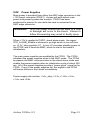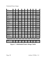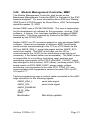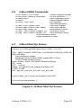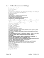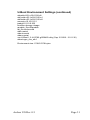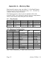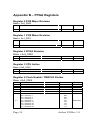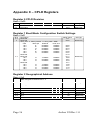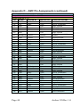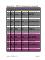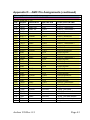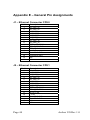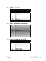
1
S
Siilliic
co
on
nT
urrn
nk
ke
eyy e
Xp
Tu
prre
essss
eX
Original Design Manufacturer
Dual-460GT AMC Card
“Arches”
Reference Design Kit
User’s Guide
Technical support: [email protected]
Silicon Turnkey Express
749 Miner Road • Highland Heights, Ohio 44143
Phone (440) 461-4700 • (800) 827-2650
Revision History
Rev
1.0
Date
Comments
Nov 25, 2008
Initial Preliminary Release
WARNING:
This document is preliminary. It may contain
errors and incomplete data.
Contact
archessupport@amcc,com for updates
Support:
Additional support information may be found at
www.amcc.com/Embedded/Downloads/Arches
or email [email protected] .
Page 2
Arches UG Rev 1.0
NOTICES
The following information is intended to alert the user to possible
dangers and important information contained within this guide.
The “WARNINGS”, “CAUTIONS” and “NOTES” do not eliminate
these dangers. Close attention to the information supplied along
with “common sense” operation is the major accident prevention
measure.
WARNING: Failure to follow this warning may result in
bodily injury.
CAUTION:
Failure to follow this caution may result in
possible damage to the board.
NOTE:
Failure to follow this note may result in
improper results from the board.
Reference Websites
Below is a list of websites that can be used to obtain additional
information and details that may not be fully provided in this
manual.
AMCC ..................................................................... www.amcc.com
Abatron JTAG Emulator……. www.ultsol.com/mfgs_emul_abtr.htm
Altera Byteblaster................................................... www.altera.com
denx Software Engineering……………………………. www.denx.de
ENEA………………………………….………….…… www.enea.com
RapidFET……………………………………….….. www.fetcorp.com
RIO Test Labs……………………………..……….. www.rio-lab.com
PICMG……………………………….………..………. www.picmg.org
Arches UG Rev 0.5
Page 3
Table of Contents
Revision History ............................................................................. 2
NOTICES ....................................................................................... 3
Reference Websites ...................................................................... 3
Table of Contents........................................................................... 4
List of Figures ................................................................................ 5
Appendix ........................................................................................ 6
General Description ....................................................................... 7
1.1
Device Placement and Functions................................. 8
1.1.01
J1 – RJ45 10/100/1000 Base-T........................... 9
1.1.02
J2 – RJ45 10/100/1000 Base-T........................... 9
1.1.04
LED 1 ................................................................... 9
1.1.05
LED 2 and 3......................................................... 9
1.1.06
LED 4 ................................................................... 9
1.1.07
P1 – JTAG Debug Port ........................................ 9
1.1.08
P2 – CPU Halt Selector ....................................... 9
1.1.09
P3 – UART Selection........................................... 9
1.1.10
P4 – CPLD JTAG Port ....................................... 10
1.1.11
P5 – FPGA Config. Device JTAG...................... 10
1.1.12
P6 – CPU0 UART Connector ............................ 10
1.1.13
P7 – UART for CPU1 or MMC Connector ......... 10
1.1.14
PWR1 – External Power Plug............................ 10
1.1.15
SW1 – AMC Ejection Switch.............................. 10
1.1.16
SW2 – Master Reset.......................................... 10
1.1.17
SW3 – Configuration Switch .............................. 11
1.2
Test Points ...................................................................... 11
2.0
Hardware Design & Architecture .................................... 12
2.1
General Description.................................................... 12
2.2
Physical Description ................................................... 12
2.3
Arches Block Diagram .................................................... 13
3.0
Control and Configuration............................................... 14
3.1
Switch Settings ........................................................... 14
3.1.1
SW1 – AMC Ejection ......................................... 14
3.1.2
SW2 – Reset Switch .......................................... 14
3.1.3
SW3 – Boot Mode Configuration ....................... 14
3.2
Jumpers...................................................................... 16
3.2.1
P2 – CPU Halt Selector ..................................... 16
3.2.2
P3 – UART Selector .......................................... 16
3.3
LEDs........................................................................... 16
4.0
Schematic ....................................................................... 17
5.0
Circuit Operation ............................................................. 18
5.01
Overview..................................................................... 18
Page 4
Arches UG Rev 1.0
5.02
Power Supplies........................................................... 19
5.03
JTAG Port................................................................... 21
5.04
Clocks......................................................................... 21
5.05
Resets ........................................................................ 22
5.06
Module Management Controller, MMC ...................... 23
5.07
CPU Configuration...................................................... 24
5.08
Interrupts .................................................................... 24
5.09
DDR2 SDRAM Memory.............................................. 24
5.10
NOR FLASH ............................................................... 24
5.11
FPGA.......................................................................... 25
5.12
I2C............................................................................... 25
5.13
UART.......................................................................... 25
5.14
Gigabit Ethernet.......................................................... 26
5.15
SGMIII Hardware Matrix............................................. 26
5.16
Serial Rapid I/O / PCI-express ................................... 26
6.0
U-Boot............................................................................. 27
6.1
U-Boot Commands ..................................................... 27
6.2
U-Boot SRIO Commands ........................................... 29
6.3
U-Boot Start Up Screen.............................................. 29
6.4
U-Boot Environment Settings ..................................... 30
Appendix A – Memory Map ......................................................... 32
Appendix B – FPGA Registers .................................................... 34
Appendix C – CPLD Registers .................................................... 36
Appendix E – General Pin Assignments...................................... 44
Acronyms and Abbreviations ....................................................... 48
List of Figures
Figure 1 – General Picture............................................................. 7
Figure 2 – Top Board Layout ......................................................... 8
Figure 3 – Bottom Board Layout.................................................... 8
Figure 4 – Test Points.................................................................. 11
Figure 5 - Arches Block Diagram................................................. 13
Figure 6 – Configuration Switch Modes....................................... 15
Figure 7 - Estimated Power Usage Table.................................... 20
Figure 8 - U-Boot Start Up Screen............................................... 29
Arches UG Rev 0.5
Page 5
Appendix
Appendix A – Memory Map ......................................................... 32
A.1 - Chip Selects.................................................................... 32
A.2 - Maximum Configuration.................................................. 32
A.3 - I2C Device Addresses .................................................... 33
Appendix B – FPGA Registers .................................................... 34
Register 0 PCB Major Revision............................................... 34
Register 1 PCB Minor Revision............................................... 34
Register 2 FPGA Revision ...................................................... 34
Register 3 CPU Active............................................................. 34
Register 4 Clock Enable / TMRCLK Divider............................ 34
Register 5 FLASH Write Protect.............................................. 35
Appendix C – CPLD Registers .................................................... 36
Register 0 CPLD Revision....................................................... 36
Register 1 Boot Mode Configuration Switch Settings ............. 36
Register 2 Geographical Address ........................................... 36
Register 3 Power On Reset High ............................................ 37
Register 4 Power On Reset Low ............................................. 37
Register 5 Ethernet Control ..................................................... 37
Register 6 UART Control, EEPROM WP, SYSERR ............... 37
Register 7 LED Control............................................................ 38
Register 8 to F Reserved......................................................... 38
Appendix E – General Pin Assignments...................................... 44
J1 – Ethernet Connector CPU0............................................... 44
J2 – Ethernet Connector CPU1............................................... 44
P1 – COP Trace Header ......................................................... 45
P2 – COP Trace CPU Selector Header .................................. 45
P3 – RS232 Selector Header .................................................. 45
P4 – CPLD Connector ............................................................. 46
P5 – Altera Byteblaster Connector .......................................... 46
P6 – RS232 Connector for CPU0............................................ 46
P7 – RS232 Connector for CPU1............................................ 47
PWR1 – Barrel Power Connector............................................ 47
Page 6
Arches UG Rev 1.0
General Description
The Arches AMC card is a reference design powered by two
PPC460GT processors. The reference design allows evaluation of
the PPC460GT processor in a dual architecture in an Advanced
Mezzanine Card (AMC). The Arches AMC can also be used as a
target system in an ATCA or MicroTCA design. Access to both
processors is provided through a variety of buses including JTAG,
1G Ethernet, PCI Express and Serial RapidIO. Each processor
has its own resource for memory, directly communicates via
Ethernet or PCI Express and can be individually configured
through an on board CPLD. The Arches AMC includes a complete
IPMI control system for machine configuration.
Figure 1 – General Picture
Arches UG Rev 0.5
Page 7
1.1
Device Placement and Functions
This section provides a description of the connectors, jumpers,
switches and main components of the board. Refer to Figure 2
and 3 for the location of the devices referenced below.
Additional descriptions of the functionality of switches, jumpers,
and LEDs along with their recommended settings will be found in
Section 3.
Figure 2 – Top Board Layout
Figure 3 – Bottom Board Layout
Page 8
Arches UG Rev 1.0
1.1.01 J1 – RJ45 10/100/1000 Base-T
J1 is a 1 Gigabyte Ethernet for CPU0.
1.1.02 J2 – RJ45 10/100/1000 Base-T
J1 is a 1 Gigabyte Ethernet for CPU1.
1.1.04 LED 1
LED1 is used by the IPMI (user provided).
1.1.05 LED 2 and 3
LEDs are bi-color (Green & Yellow) and are user
defined. See CPLD register 4 for details.
1.1.06 LED 4
LED 4 is bi-color (Red & Green) and is user defined.
See CPLD register 4 for details.
1.1.07 P1 – JTAG Debug Port
P1 is a 16 pin port used to debug either CPU0 or CPU1.
1.1.08 P2 – CPU Halt Selector
P2 is a 4 pin header used to halt either or both CPUs for
debugging. Use a jumper for selection as follows:
Jumper
1-2
3-4
1-2
3-4
CPU
0
1
Both
1.1.09 P3 – UART Selection
P3 is a 2 pin header used to select either the MMC
UART or CPU1 UART at connector P7.
Open = CPU1
Jumped = MMC
Arches UG Rev 0.5
Page 9
1.1.10 P4 – CPLD JTAG Port
P4 is a 10 pin header used to program and debug the
CPLD, confirming to the industry-standard pinout used
by probe manufacturers such as Abatron, Green Hills,
Lauterbach, Wind River and others.
1.1.11 P5 – FPGA Config. Device JTAG
P5 is a 10 pin header used to configure and debug the
FPGA. A standard Altera Byteblastter can be used with
this connector.
1.1.12 P6 – CPU0 UART Connector
P6 is a standard DB9 connector used to access CPU0’s
UART.
1.1.13 P7 – UART for CPU1 or MMC Connector
P7 is a standard DB9 connector and is used with jumper
P5 to select either CPU1’s UART or the MMC’s UART.
1.1.14 PWR1 – External Power Plug
PWR1 is used with an external wall ‘cube’ power supply
for standalone operation, such as the 12V power
adapter included in the kit.
WARNING:
DO NOT USE EXTERNAL POWER WHEN
AMC EDGE CONNECTOR IS POWERED.
1.1.15 SW1 – AMC Ejection Switch
SW1 is actuated by the front panel ejection leveler and
provides an input to by the IPMI system (user provided).
1.1.16 SW2 – Master Reset
SW2 is a single button switch which provides a power on
reset to the module.
Page 10
Arches UG Rev 1.0
1.1.17 SW3 – Configuration Switch
SW3 is a four position switch that set the boot mode for
the CPUs.
1.2
Test Points
TP
01
02
03
04
05
06
07
08
09
10
11
12
13
14
15
16
17
18
19
Function
ESD DISCHARGE STRIP
ESD DISCHARGE STRIP
U1D, PIN AM33/34, DDR-1 Mem DCF
U2D, PIN AM33/34, DDR-2 Mem DCF
U37 (88E1112), PIN 34, TSTPT
U37 (88E1112), PIN 25, HSDAC_P
U37 (88E1112), PIN 26, HSDAC_N
U38 (88E1112), PIN 34, TSTPT
U38 (88E1112), PIN 25, HSDAC_P
U38 (88E1112), PIN 26, HSDAC_N
U39 (88E1112), PIN 34, TSTPT
U39 (88E1112), PIN 25, HSDAC_P
U39 (88E1112), PIN 26, HSDAC_N
U40 (88E1112), PIN 34, TSTPT
U40 (88E1112), PIN 25, HSDAC_P
U40 (88E1112), PIN 26, HSDAC_N
U45 (74LVC2G66) PIN 2, 1B
U45 (74LVC2G66) PIN 1, 1A
U45 (74LVC2G66) PIN 7, 1CNT
Figure 4 – Test Points
Arches UG Rev 0.5
Page 11
2.0
Hardware Design & Architecture
2.1
General Description
Features
• Two PowerPC 460GT 1.0GHz CPUs
• CPUs interconnected via
•
•
•
•
•
•
•
•
•
•
•
•
•
•
− Shared memory
− GigE
− PCI-express, x1
Two 512MB DDR2 subsystems
Two 64MB NOR FLASH
Two UART Ports
Two 10/100/1000 Ethernet RJ45 Ports
Two EEPROM (up to 64KB) via I2C
Two Temperature Sensor via I2C
Four 10/100/1000 Ethernet AMC Ports
One x4 sRIO AMC Port
One x1/x4 PCI-e/sRIO AMC Port
Management Module Controller Support
Shared JTAG Connector
Linux 2.6
Usable Stand-Alone or ATCA Chassis
Full Compliance:
−
−
−
−
AMC.2 E2 (GE)
AMC.1 (PCI-e)
AMC.4 (sRIO)
SCOPE
2.2
Physical Description
Board Size.......................................180mm x 74mm
Power Requirement………….….. 12vDC @ 40watts
Operating Temperature:
0
Standard……………………………… 0-50 C
Extended…………………………………. TBD
Weight............................................................... 400g
RoHS........................................................ Compliant
Page 12
Arches UG Rev 1.0
2.3
Arches Block Diagram
Figure 5 - Arches Block Diagram
Arches UG Rev 0.5
Page 13
3.0
Control and Configuration
3.1
Switch Settings
This section provides a brief description of the functionality
and recommended settings for the switches.
Refer to Figure 2 in Section 1 for the locations of these
switches.
3.1.1 SW1 – AMC Ejection
This switch provides information to the IPMI that allows the
AMC to be ejected from the AMC connector. This function
is NOT implemented and is the responsibility of the user.
3.1.2 SW2 – Reset Switch
This is a push button switch when in the stand alone mode
provides a Power On Reset to the CPLD which will reset
both CPUs, the MMC and the CPLD.
3.1.3 SW3 – Boot Mode Configuration
This 4 position switch provides inputs to the CPLD that
sets board boot options and frequencies.
See Figure 6, Configuration Switch Modes for switch
settings.
See Section 5.07, CPU Configuration for more information
about the Boot Mode Configurations.
See CPLD Register 1 for additional information.
Page 14
Arches UG Rev 1.0
SW3 Boot Mode Configuration (continue)
Switch
Position
Switch Function
1
2
3
4
Boot Opt
SYSCLK
PCIe_CLK
0
0
0
0
E
66.6MHz
100MHz
0
0
0
1
B
66.6MHz
100MHz
0
0
1
0
G
66.6MHz
100MHz
0
0
1
1
E
66.6MHz
125MHz
0
1
0
0
B
66.6MHz
125MHz
G
66.6MHz
125MHz
0
1
0
1
0
1
1
0
Reserved
0
1
1
1
Reserved
1
0
0
0
G
74.9MHz
100MHz
1
0
0
1
G
83.3MHz
100MHz
1
0
1
0
G
99.9MHz
100MHz
1
0
1
1
1
1
0
0
G
74.9MHz
125MHz
1
1
0
1
G
83.3 MHz
125MHz
G
83.3MHz
125MHz
1
1
1
0
1
1
1
1
Reserved
Reserved
Figure 6 – Configuration Switch Modes
Arches UG Rev 0.5
Page 15
3.2
Jumpers
This section provides a brief description of the functionality
and recommended settings for the jumpers. Refer to
Figure 2 in Section 1 for the locations of these jumpers.
3.2.1 P2 – CPU Halt Selector
Default Open
This jumper is to select which CPU that is connected to
the COP Debug Port, P1. Positions are CPU0, CPU1 or
both.
3.2.2 P3 – UART Selector
Default Open
This jumper is selects either the MMC UART or the CPU1
UART. In the normally open (no jumper) CPU1 UART is
selected. When the jumper is installed the MMC UART is
connected to UART xx, Px
3.3
LEDs
This section provides a list of functions for the LEDs.
Refer to Figure 2 for the locations of these LEDs.
See CPLD Register 7, Addendum C, for more information.
LED
1
2
3
4
Page 16
Function
AMC Eject
User Defined
User Defined
User Defined
Color
Blue
Grn/Yel
Grn/Yel
Grn/Red
Arches UG Rev 1.0
4.0 Schematic
The schematic and basic assembly information in a portable
document format for the Arches can be downloaded via
www.amcc.com/Embedded/Downloads/Arches.
The Arches AMC design can be customized for optional flexibility
and custom interfaces so the embedded systems engineer can
obtain a lower overall parts cost using a variety of fixed and user
selectable options.
These options inherently are contained in connectors, jumpers and
switches on the board.
The schematic provides guidelines for using the already installed
as well as user modifiable options available on the present design.
Arches UG Rev 0.5
Page 17
5.0
Circuit Operation
5.01
Overview
The Arches reference design is based on two PPC460GT
processors in an AMC form factor. CPU1 is a mirror of CPU0 for
local resources (each has its own local bus FLASH, I2C device,
UART, Gigabit Ethernet, SRIO/PCI-e and DDR2 SDRAM
interface). Both processors interface to an FPGA for shared
memory. The processors share clock generators and a single
power supply. The processors communicate to each other by
Giga-bit Ethernet (SGMII) and a 1x PCI-e bus.
On board interrupts are hard wired to the CPUs. See section 5.08
for complete interrupt information.
Only CPU0 communicates with the Management Module
Controller, MMC, via a SPI bus. The Intelligent Platform
Management Interface (IPMI) communications to the AMC
edge connector is generated by the MMC. The user is responsible
to implement the IPMI software. The MMC communicates the
following to the FPGA:
Enable power supplies
Take CPUs out of reset
USER LEDs
Ethernet resets
Read geographical address
The CPLD reads the configuration switches and communicates
them to the CPUs and sets clock configuration to the clock
generators. The CPLD drives the signals, but receives the
information from the MMC across the MMC I2C bus.
Page 18
Arches UG Rev 1.0
5.02
Power Supplies
Main power is provided from either the AMC edge connector or the
+12V barrel connector (PWR1). Arches will auto-detect main
power and properly power the module. PWR1 has been
positioned to prevent its use while the card is connected to an
AMC edge connector.
WARNING: Only one power source can be used at a time
or damage will occur to the board. Failure to
follow this warning may result in bodily injury.
When +12V is applied to PWR1, stand alone mode, the signal
STD_ALONE_Enable is allowed to go high which in turn will turn
on +3.3V_stby regulator U7. In turn U7 provides standby power to
the FPGA, and if used the MMC, which is vital to the board’s
initialization.
The main power supplies are enabled by the FPGA. The FPGA
initializes the power supplies when in the AMC mode. The FPGA
by-passes the MMC communication in the stand alone mode and
enable the power supplies after an initialization cycle of about 300
ms. All of the power supplies provide a “power good” signal to the
FPGA. If any of the power supplies fail, this signal to the FPGA
will cause Arches to shut down immediately.
Power supply rails include: +3.3v_stby; +3.3v; +1.25v; +2.5v;
+1.8v; and +0.9v.
Arches UG Rev 0.5
Page 19
Estimated Power Usage:
Device
Qty
AMCC 460GT_0
3.3v
stby
1
AMCC 460GT_1
1
U15
1
U17
1
U18
1
0.050
LEDs
1
0.010
LEDs
7
U19 & U20
2
3.3v
2.5v
1.25v
Total
0.5000
0.5000
1.8v
0.9v
1.2v
4.20
8.15000
0.5000
0.5000
4.20
8.15000
0.050
0.16500
0.0500
0.16500
0.16500
0.03300
0.0100
0.03300
0.016
0.05280
U3 & U4
2
0.1000
ICS8402
1
0.1530
0.33000
0.50490
ICS844246
1
0.2610
0.86130
PSs
3
2.5000
8.25000
UARTS
2
0.0200
0.06600
UARTS
1
U24
1
0.0150
U45
1
0.1000
U25 & U26
2
0.1800
DDR2 CPU_0
4
1.40
1.40
DDR2 CPU_1
4
1.40
1.40
EEPROM
2
0.0030
0.00990
Temp Sensor
2
0.0012
0.00396
Enet Phy
4
Totals
0.020
0.06600
0.04950
0l05
0.25
0.75500
0.59400
3.78000
3.78000
0.2470
0.162
0.8024
2.0380
0.99430
11.20
11.20
1.51
8.40
37.11000
Figure 7 - Estimated Power Usage Table
Page 20
Arches UG Rev 1.0
5.03
JTAG Port
The JTAG port is configured as a single connector, P1, with both
processors daisy chained together with the CPU0, U1, as the first
in the chain.
When using an Abatron BDI2000/3000 probe, the configuration
script has to be modified and a jumper, P2, placed depending on
which CPU is be interrogated.
CPU0:
Jumper P2 pins 1 and 2 (Halts CPU1)
Script: SCANSUCC 1 0x07
CPU1:
Jumper P2 pins 3 and 4 (Halts CPU0)
Script: SCANPRED 1 0x07
5.04
Clocks
The main on board system clocks are controlled by U3. The
system clock controls the CPUs, the FPGA, and the CPLD. The
output clocks are set by the CPLD driving SYS_CLK_SEL1…3
signals to U3 and be set to the frequencies as follows:
66.66667MHz
74.99999MHz
83.33333MHz
99.99999MHz
SYS_CLK_SEL3…1 = 000
SYS_CLK_SEL3…1 = 001
SYS_CLK_SEL3…1 = 010
SYS_CLK_SEL3…1 = 100
The PCI-express clock is controlled by U4. The CPLD controls U4
with the CLK_N_SEL1…0 signal and can be set to the following
frequencies:
125MHZ
100MHZ
Arches UG Rev 0.5
CLK_N_SEL1…0 = 01
CLK_N_SEL1…0 = 10
Page 21
5.04
Clocks (continued)
Y3 is a stand alone oscillator providing a 50MHz clock to the
FPGA. The FPGA generates each CPU’s TMRCLK independent
from each other. Currently the FPGA does not manipulate this
clock, but the FPGA can change it, if necessary.
Y4 is a stand alone oscillator providing a 50Mz clock to each CPU
for Ethernet management.
5.05
Resets
Arches resets are generated from the AMC connector in the AMC
Mode or the FGPA in the stand alone mode.
In the stand alone mode the MCLR# signal is the same as the
AMCE_ENABLE# and is pulled high after an initial time out period
of about 300 ms. This allows the use of the AMC connector for
debug of the MMC. A custom cable is required for the AMC
connector. In this mode the CPLD will control the board bring up
based on the power being enabled and the initial time out period of
about 300 ms. Switch SW2 will provide a Power-On-Reset to the
CPLD which resets both CPUs, the MMC, and the CPLD.
In the AMC mode the MCLR# signal is the opposite of the
AMCE_ENABLE# signal. In this mode after the initial release of
the AMCE_ENABLE# signal the MMC communicates to the CPLD
via the MMC I2C bus. The MMC writes a specific value to the
CPLD boot register (see Appendix C, Register 5).
The MMC monitors all the voltage rails and should one voltage fail
will reset the AMC board. This event powers down all power
supplies except the standby power.
Page 22
Arches UG Rev 1.0
5.06
Module Management Controller, MMC
The Module Management Controller, also known as the
Baseboard Management Controller (BMC) is the heart of the IPMI
based subsystem. For more information about IPMI see ‘Making
IPMI Work in ATCA Designs’ by Steve Rokov, OSA Technologies,
dated November 10, 2004.
Arches’ MMC uses a PIC24FJ64GA002. The user is responsible
for the development of software for this processor, such as, IPMI
software. A jumper, Pxx, has been installed to by-pass all MMC
functionality. Functions required by Arches by the MMC will be
handled by the CPLD/FPGA.
Neither AMCC nor STx provides support for user-developed MMC
software. However an example of minimum MMC functionality
would include communicating to the TCA or uTCA blade via the
I2C bus AMCE_SDA_L, serial data signal and the AMCE_SCL,
serial clock signal. The MMC would also use the I2C to
communicate to the CPLD (in the stand alone mode this is not
necessary, if the default values are acceptable). The MMC is also
is responsible for controlling: monitoring reset switches and
generating reset signals to the CPLD (the MMC_CLKOUT signal
was changed to this function); LED1 (blue); hot swap switch, SW1;
board resets via SW2; MMC UART; power supply voltage
monitoring; communication to the main CPU, CPU0, U1; and
communicating with temperature sensors for each CPU via I2C,
U16 and U17.
Factory programming uses a custom cable connected to the AMC
edge connector for the following signals:
AMCE_SDA_L
AMCE_SCL
AMCE_ENABLE#
+3.3v_stby
GND
Bootloader
Arches UG Rev 0.5
serial data signal
serial clock signal
Microchip updater
Page 23
5.07
CPU Configuration
The CPUs’ initial configuration is controlled by the CPLD and
configuration switch SW3. The CPLD provides the following
signals:
CPU0_boot_CFG0…1
CPU1_boot_CFG0…1
SYS_CLK_SEL1…3
CLK_N_SEL0…1
Bootstrap signal to CPU0
Bootstrap signal to CPU1
Main system clock frequency
PCI-e clock frequency
See the CPLD register 2, Appendix C, for complete configurations.
5.08
Interrupts
All Arches interrupts are directly connected to the processors.
The following list the IRQs and their signals.
Interrupt
CPU0_IRQ00
CPU0_IRQ01
CPU0_IRQ02
CPU1_IRQ00
CPU1_IRQ01
CPU1_IRQ02
5.09
Driven From
ETH0_INT
ETH1_INT
CPU0_TEMP_IRQ#
ETH2_INT
ETH3_INT
CPU1_TEMP_IRQ#
DDR2 SDRAM Memory
Each CPU has a dedicated DDR2 memory bus. Each bus is 64
bit, has a single bank of 512 MB with a maximum speed of 400
MHz, and no Error Checking and Correction. Each bus is directly
controlled by each CPU’s SDRAM controller.
5.10
NOR FLASH
Each CPU has dedicated 64 MByte of NOR FLASH on the x16 bit
bus. The FLASH uses chip select PerCS0#.
Page 24
Arches UG Rev 1.0
5.11
FPGA
The FPGA requires a configuration device. The configuration
device is programmed with an Altera Byteblaster II cable or
equivalent plugged in to P5. It is recommended to use the Active
Programming setting within the Altera Quartus software.
The main function of the FPGA is to provide 2 Mbytes of shared
memory via the x 16bit bus to both processors. It provides
address decodes as follows:
Address 12-15 (b0000) is FPGA board control and status
registers.
Address 12-15 (b1000) is CPLD board control and status
registers (Only CPU_0 can access the CPLD).
Address 12-15 (b1100) is shared memory
See FPGA registers for additional board address decodes and
board control and status registers.
The FPGA provides clocks CLK_TMRCLK0 and CLK_TMRCLK1.
These are independent clocks based on the input clock
CLK_TMRCLK_OSC and default to 50 MHz. These clocks can be
modified by the FPGA.
All FPGA code can be modified to suite specific needs.
5.12
I 2C
Each CPU has an EEPROM (address A8) and temperature sensor
(address 94) on the I2C0 bus.
5.13
UART
Each CPU has a UART port. CPU0 is connected to P6 through a
transceiver. CPU1’s UART is shared with the MMC controller and
is selected with jumper P3. The default of P3 (jumper installed)
connects CPU1 to the UART.
The UART connectors (P6 and P7) use a small Molex connector
and require a custom cable (one supplied in the RD-460GT-KIT01) to a standard DB9 connector. See Appendix D for pin
assignments of these connectors.
Arches UG Rev 0.5
Page 25
5.14
Gigabit Ethernet
Each CPU has two Gigabit Ethernet connected to the CPU’s
Ethernet management interface using SGMII. The Ethernet use a
Marvel 88E1112 ‘PHY’ for either a 10/100/1000Base-T or 1.25
GHz SERDES. The PHY is configured to take advantage of the
Media DetectionTM mode for copper or fiber support. The PHY is
connected to an RJ45 connector on the front panel for Ethernet
support and 1.25GHz SERDES on the AMC edge connector.
NOTE: Only one interface can be used at a time.
The other Ethernet PHY is wired for 1.25GHz SERDES on the
AMC edge connector.
Both CPUs are connected directly together (AC Coupled) using the
SGMII 0 ports.
5.15
SGMIII Hardware Matrix
Both CPUs are wired exactly the same, except SGMII0 Rx on
CPU0 is connected to SGMII0 Tx on CPU1.
EMAC0
CPU0_SGMII 0
CPU1_SGMII 0
EMAC1
SGMII 1
Ethernet PHY address 0000
EMAC2
SGMII 2
Ethernet PHY address 0001
5.16
Serial Rapid I/O / PCI-express
There are two independent PCI Express interfaces compliant to
specification 1.1. One interface can be configured as one to four
lanes while the other functions as one lane only. The four lane
interface shares a high speed SERDES with the Serial Rapid IO
(SRIO) interface. Both can be Root or Endpoint Ports.
The CPU’s PCIe0 port is used for communicating between
processors using the x1 lane PCIe bus. PCIe is serial interface
and is AC coupled from TX on CPU0 to RX on CPU1 and RX on
CPU0 to TX on CPU1.
The x4 PCIe bus is multiplexed with the x4 SRIO bus and routed to
the AMC edge connector. See AMCC 460GT documentation for
details.
Page 26
Arches UG Rev 1.0
6.0 U-Boot
6.1
U-Boot Commands
?
askenv
autoscr
base
bdinfo
boot
bootd
bootelf
bootm
bootp
bootstrap
bootvx
cmp
coninfo
cp
crc32
dcache
dhcp
dtt
echo
eeprom
erase
exit
fdt
flinfo
getdcr
getidcr
go
help
icache
icrc32
iloop
imd
iminfo
imls
imm
- alias for 'help'
- get environment variables from stdin
- run script from memory
- print or set address offset
- print Board Info structure
- boot default, i.e., run 'bootcmd'
- boot default, i.e., run 'bootcmd'
- Boot from an ELF image in memory
- boot application image from memory
- boot image via network using BootP/TFTP protocol
- program the I2C bootstrap EEPROM
- Boot vxWorks from an ELF image
- memory compare
- print console devices and information
- memory copy
- checksum calculation
- enable or disable data cache
- invoke DHCP client to obtain IP/boot params
- Digital Thermometer and Thermostat
- echo args to console
- EEPROM sub-system
- erase FLASH memory
- exit script
- flattened device tree utility commands
- print FLASH memory information
- Get an AMCC PPC 4xx DCR's value
- Get a register value via indirect DCR addressing
- start application at address 'addr'
- print online help
- enable or disable instruction cache
- checksum calculation
- infinite loop on address range
- i2c memory display
- print header information for application image
- list all images found in flash
- i2c memory modify (auto-incrementing)
Arches UG Rev 0.5
Page 27
U-Boot Commands (continued)
imw
imxtract
inm
interrupts
iprobe
irqinfo
itest
loadb
loads
loady
loop
loopw
md
mdc
mii
mm
mtest
mw
mwc
nfs
nm
ping
printenv
protect
rarpboot
reginfo
reset
rio
run
saveenv
setdcr
setenv
setidcr
sleep
test
tftpboot
version
Page 28
- memory write (fill)
- extract a part of a multi-image
- memory modify (constant address)
- enable or disable interrupts
- probe to discover valid I2C chip addresses
- print information about IRQs
- return true/false on integer compare
- load binary file over serial line (kermit mode)
- load S-Record file over serial line
- load binary file over serial line (ymodem mode)
- infinite loop on address range
- infinite write loop on address range
- memory display
- memory display cyclic
- MII utility commands
- memory modify (auto-incrementing)
- simple RAM test
- memory write (fill)
- memory write cyclic
- boot image via network using NFS protocol
- memory modify (constant address)
- send ICMP ECHO_REQUEST to network host
- print environment variables
- enable or disable FLASH write protection
- boot image via network using RARP/TFTP protocol
- print register information
- Perform RESET of the CPU
- list and access RapidIO devices
- run commands in an environment variable
- save environment variables to persistent storage
- Set an AMCC PPC 4xx DCR's value
- set environment variables
- Set a register value via indirect DCR addressing
- delay execution for some time
- minimal test like /bin/sh
- boot image via network using TFTP protocol
- print monitor version
Arches UG Rev 1.0
6.2
U-Boot SRIO Commands
rio init <lanes 1 or 4> <hdid>
rio test <cmd> <delay in mseconds>
rio reset <cmd>
rio status
rio dump <reg> <did>
- initialize RapidIO interface
- run test (cmd=link,...)
- reset (cmd=rsync,tsync)
- display RapidIO status
- print registers
(reg=sdr|cfg|reg|mnt)
rio read <reg> <offset> <did>
- read <reg> register
rio write <reg> <offset> <did> <data>
- write <reg> register
rio dbell <did> <data> <n>
- send doorbell n times
rio mem <did> <offset> <length> <n> - send data n times
rio msg <did> <mbox> <length> <n> - send message n times
n=pos transmits n times
n=neg retransmits n times
6.3
U-Boot Start Up Screen
U-Boot 1.3.4-03792-gf556483-dirty (Sep 15 2008 - 21:21:30)
CPU: AMCC PowerPC 460GT Rev. A at 800 MHz (PLB=200, OPB=100,
EBC=100 MHz)
Security/Kasumi support
Bootstrap Option B - Boot ROM Location EBC (16 bits)
32 kB I-Cache 32 kB D-Cache
Board: Arches - AMCC PPC460GT Reference Design
I2C: ready
DTT: 1 is 25 C
DRAM: 512 MB (ECC not enabled, 400 MHz, CL3)
FLASH: 32 MB
Net: ppc_4xx_eth0, ppc_4xx_eth1, ppc_4xx_eth2
Type run flash_nfs to mount root filesystem over NFS
Hit any key to stop autoboot: 0
Figure 8 - U-Boot Start Up Screen
Arches UG Rev 0.5
Page 29
6.4
U-Boot Environment Settings
bootcmd=run flash_self
bootdelay=5
baudrate=115200
loads_echo=
preboot=setenv ethact ppc_4xx_eth1;echo;echo Type "run flash_nfs"
to mount root filesystem over NFS;echo;
hostname=arches
netdev=eth1
nfsargs=setenv bootargs root=/dev/nfs rw
nfsroot=${serverip}:${rootpath}
ramargs=setenv bootargs root=/dev/ram rw
addip=setenv bootargs ${bootargs}
ip=${ipaddr}:${serverip}:${gatewayip}:${netmask}:${hostname}:${netd
ev}:off panic=1
addtty=setenv bootargs ${bootargs} console=ttyS0,${baudrate}
addmisc=setenv bootargs ${bootargs}
initrd_high=30000000
kernel_addr_r=400000
fdt_addr_r=800000
ramdisk_addr_r=C00000
hostname=arches
rootpath=/opt/eldk/ppc_4xxFP
flash_self=run ramargs addip addtty addmisc;bootm ${kernel_addr}
${ramdisk_addr} ${fdt_addr}
flash_nfs=run nfsargs addip addtty addmisc;bootm ${kernel_addr} ${fdt_addr}
net_nfs=tftp ${kernel_addr_r} ${bootfile}; tftp ${fdt_addr_r} ${fdt_file};
run nfsargs addip addtty addmisc;bootm ${kernel_addr_r} ${fdt_addr_r}
net_self_load=tftp ${kernel_addr_r} ${bootfile};tftp ${fdt_addr_r}
${fdt_file};tftp ${ramdisk_addr_r} ${ramdisk_file};
net_self=run net_self_load;run ramargs addip addtty addmisc;bootm
${kernel_addr_r} ${ramdisk_addr_r} ${fdt_addr_r}
load=tftp 200000 arches/u-boot.bin
update=protect off 0xFFFA0000 FFFFFFFF;era 0xFFFA0000
FFFFFFFF;cp.b ${fileaddr} 0xFFFA0000 ${filesize};setenv
filesize;saveenv
upd=run load update
kernel_addr=fe000000
fdt_addr=fe1e0000
ramdisk_addr=fe200000
pciconfighost=1
pcie_mode=RP:RP
Page 30
Arches UG Rev 1.0
U-Boot Environment Settings (continued)
ethaddr=00:1e:59:1f:00:a0
eth1addr=00:1e:59:1f:00:a1
eth2addr=00:1e:59:1f:00:a2
serverip=10.10.0.121
ipaddr=10.10.0.252
bootfile=uImage uImage
ramdisk_file=uRamdisk
fdt_file=arches.dtb
stdin=serial
stdout=serial
stderr=serial
ver=U-Boot 1.3.4-03792-gf556483-dirty (Sep 15 2008 - 21:21:30)
ethact=ppc_4xx_eth1
Environment size: 1788/16379 bytes
Arches UG Rev 0.5
Page 31
Appendix A – Memory Map
Board specific memory map, see table 4-1 of the Rigel/Calypso,
Engineering Architecture Specification Rev. 1.01 – 10/12/07 for
complete memory map information.
The following memory map is only an example; refer to the
PowerPC 460GT user manual for specific memory configurations,
many of the memory map setting are user defined.
A.1 - Chip Selects
Chip Select
PerCS0#
PerCS1#
PerCS2#
Function
NOR FLASH
FPGA
-
Address
0xFC00_0000
0x4000_0000
-
Size
64MB
2MB
-
BankSel0#
DDR2
0x0000_0000
512MB
Description
X16 BUS, EBC
X16 BUS, EBC
X64 BUS,
DDR2
A.2 - Maximum Configuration
32 Bit Address
Start
Function
CS#
Size/Reserved
End
0x0000_0000 0x1FFF_FFFF DDR SDRAM
DDR CS0# 512MB/512MB
0x8000_0000 0x0003_FFFF SRAM (L2 Cache)
-
0xF000_0000 0xFFFF_FFFF BOOT Space EBC
PBus* CS0# 256MB/256MB
32KB/256KB
0x8000_0000 0x801F_FFFF FPGA
PBus* CS2# 2MB/2MB
Local Configuration
0xEF40_0000 0xEF40_003F Registers
64B/1KB
0xEF60_0300 0xEF60_0307 UART0
8B/†16KB
0xEF60_0700 0xEF60_071F IIC0
32B/†16KB
0xEF60_0900 0xEF60_0906 SPI
7B/†16KB
0xEF60_0E00 0xEF60_0EFF Enet 0
256B/†16KB
0xEF60_0F00 0xEF60_0FFF Enet 1
256B/†16KB
PCI-x & SRIO
PCI-x Interrupt
Notes: * PBus is Peripheral Bus; † 16KB is total for these Functions.
Page 32
Arches UG Rev 1.0
A.3 - I2C Device Addresses
Bus Description
Address
MMC to AMC
MMC to CPLD
CPU0, I2C0
CPU0, I2C0
CPU1, I2C0
CPU1, I2C0
TBD
TBD
A8
94
A8
94
Arches UG Rev 0.5
Connected
U14 to AMC
Connector
U14 to U18
U1 to U33
U1 to U35
U2 to U34
U2 to U36
MFG. Device PN
Microchip
PIC24FJ64GA002
Atmel AT24C32
ADI AD7414-0
Atmel AT24C32
ADI AD7414-0
Page 33
Appendix B – FPGA Registers
Register 0 PCB Major Revision
Base + 0x0_0000
Bit #
PCB revision used with reg 1, example is rev 01.00
Reset Value
Bit Type
0x01
Read Only
Reset Value
Bit Type
0x00
Read Only
Where 01 is read in reg 0 and 00 is read in reg 1
0-7
Upper byte of Board ID
Register 1 PCB Minor Revision
Base + 0x1_0001
Bit #
PCB revision used with reg 0, example is rev 01.00
Where as 01 is read in reg 0 and 00 is read in reg 1
0-7
Lower byte of Board ID
Register 2 FPGA Revision
Base + 0x2_0002
Bit #
FPGA revision
0-7
FPGA revision information
Reset Value
Bit Type
0x01
Read Only
Register 3 CPU Active
Base +0x3_0003
Bit #
FPGA Revision
0-7
Only read by one CPU
Reset Value
Bit Type
0x01
Read Only
Register 4 Clock Enable / TMRCLK Divider
Base +0x4_0004
Bit #
0
1
2
3
4
5-7
Description
CLK_GMCRefClk_EN
CLK_TMRCK_EN
Reserved
Reserved
Reserved
TMRCLK div, based on 4 input
000 = divide by 1
001 = divide by 2
010 = divide by 4
011 = divide by 6
100 = divide by 10
101 = divide by 20
110 = divide by 40
111 = divide by 50
Page 34
1 = enabled
1 = enabled
Reset Value
0
0
0
0
0
Bit Type
Read/Write
Read/Write
Read/Write
Read/Write
Read/Write
(50MHz)
000
001
010
011
100
101
110
111
Read/Write
Arches UG Rev 1.0
Register 5 FLASH Write Protect
Base +0x5_0005
Bit #
0
Description
FLASH0_WPn
1 = enabled
Reset Value
1
Bit Type
Read/Write
1
FLASH0_RY_BYN
MASK bit
0 = hold low
1 = pass through to CPU
1
Read/Write
2
3
Reserved
1
Read/Write
Reserved
1
4
FLASH1_WPn
Read/Write
1 = enabled
1
5
FLASH1_RY_Byn
MASK bit
Read/Write
0 = hold low
1 = pass through to CPU
1
Read/Write
6
7
Reserved
1
Read/Write
Reserved
1
Read/Write
Arches UG Rev 0.5
Page 35
Appendix C – CPLD Registers
Register 0 CPLD Revision
Base +0x00
Bit #
0-7
Description
CPLD revision
information
Reset Value
Bit Type
0x01
Read Only
Register 1 Boot Mode Configuration Switch Settings
Base +0x01
Bit #
0-2
3
4-7
Description
Reserved
Reserved
CFG_sw0…3, switch position 1 = CFG_SW0 = MSB
CPU
Boot Opt
SYSCLK
PCIe CLK
1&2
E
66.6MHz
100MHz
1&2
B
66.6MHz
100MHz
1&2
G
66.6MHz
100MHz
1&2
E
66.6MHz
125MHz
1&2
B
66.6MHz
125MHz
1&2
G
66.6MHz
125MHz
Reserved
Reserved
1&2
G
74.9MHz
100MHz
1&2
G
83.3MHz
100MHz
1&2
G
99.9MHz
100MHz
Reserved
1&2
G
74.9MHz
125MHz
1&2
G
83.3MHz
125MHz
1&2
G
83.3MHz
125MHz
1&2
G
99.9MHz
125MHz
Reset Value
xxx
0000
0000
0001
0010
0011
0100
0101
0110
0111
1000
1001
1010
1011
1100
1101
1110
1111
Bit Type
Read Only
Read Only
Register 2 Geographical Address
Base +0x2
Bit #
AMC Geograhical address bits 0…2
2 bits for every address bit
00 = low
01 = high
11 = 3-state
Reset Value
Bit Type
0
Reserved
x
Read Only
1
Reserved
0
Read Only
2-3
Bit 0
xx
Read Only
4-5
Bit 1
00
Read Only
6-7
Bit 2
xx
Read Only
Page 36
Arches UG Rev 1.0
Register 3 Power On Reset High
Base +0x03
Bit #
0-7
In AMC mode the MMC must write 0x55
before the board will boot
When running, if the MMC writes 0xAA to
register 04 and 0x55 to register 5 the board
will reset and be in a powered down state
CPLD POR = 0xAA, reg. 4 & 5 need to be set
Reset Value
Bit Type
0x55
Read/Write
Register 4 Power On Reset Low
Base +0x04
Bit #
0-7
In AMC mode the MMC must write 0xAA
before the board will boot
When running, if the MMC writes 0xAA to
register 4 and 0x55 to register 5 the board
will reset and be in a powered down state
CPLD POR = 0x55, reg. 4 & 5 need to be set
Reset Value
Bit Type
0xAA
Read/Write
Reset Value
Bit Type
0
0
0
0
1
1
1
1
Read/Write
Read/Write
Read/Write
Read/Write
Read/Write
Read/Write
Read/Write
Read/Write
Register 5 Ethernet Control
Base +0x05
Bit #
0
1
2
3
4
5
6
7
Controls which IRQ is used for the listed IRQs
0 = IRQ0_CPU0, 1 = IRQ1_CPU0
ETH0_RESET, Active Low
ETH1_RESET, Active Low
ETH2_RESET, Active Low
ETH3_RESET, Active Low
ETH0_RESET, Active High
ETH1_RESET, Active High
ETH2_RESET, Active High
ETH3_RESET, Active High
Register 6 UART Control, EEPROM WP, SYSERR
Base +0x06
Bit #
0
1
2
3
4
5
6
7
Controls which IRQ is used for the listed IRQs
0 = IRQ_CPU0, 1 = IRQ1_CPU0
CPU0_FPRCEPFF 0 = shut off
CPU0_EEP_WP
1 = Write Protect
Reserved
SYSERR_CPU0
CPU1_FORCEOFF
0 = shut off
CPU1_EEP_WP
1 = Write Protect
Reserved
SYSERR_CPU1
Arches UG Rev 0.5
Reset Value
Bit Type
1
0
0
0
1
0
0
0
Read/Write
Read/Write
Read/Write
Read Only
Read/Write
Read/Write
Read/Write
Read Only
Page 37
Register 7 LED Control
Base +0x07
Bit #
0
1
2
3
4
5
6
7
LEDs are Bi-Color and controlled in pairs
LED 2, LED_UESER 1, Green
LED 2, LED_UESER 2, Yellow
LED 3, LED_UESER 3, Green
LED 3, LED_UESER 4, Yellow
User override for USER_LEDS
0 = default = status information
LEDS changing colors, heart beat
1 = User control
User override for STATUS LEDS
0 = default = status information
RED = reset, else green
1 = User control
LED_STATUS2, Red
LED_STATUS3, Green
Reset Value
0
1
1
0
Bit Type
Read/Write
Read/Write
Read/Write
Read/Write
0
Read/Write
0
Read/Write
1
0
Read Only
Read Only
Reset Value
0
0
0
0
0
0
0
0
Bit Type
Read/Write
Read/Write
Read/Write
Read/Write
Read/Write
Read/Write
Read/Write
Read/Write
Register 8 to F Reserved
Base +0x0x (where xx is registers 8 to F
Bit #
0
1
2
3
4
5
6
7
Bit Description
Reserved
Reserved
Reserved
Reserved
Reserved
Reserved
Reserved
Reserved
Page 38
Arches UG Rev 1.0
Appendix D – AMC Pin Assignments
Existing SRIO Ports per AMC.4
Disputed Ports between AMC.4 & SCOPE
Scope Ports per V 1.0
PIN
SIGNAL
DRIVEN BY
MATING PIN
1
GND
First
2
PWR
Carrier
First
3
PS1#
AMC L
Last
4
MP
Carrier
Second
5
GA0
Carrier
Second
6
Reserved
Second
7
GND
First
8
Reserved
Second
9
PWR
Carrier
First
10
GND
First
11
TX0+
AMC
Third
12
TX0AMC
Third
13
GND
First
14
RX0+
Carrier
Third
15
RX0Carrier
Third
16
GND
First
17
GA1
Carrier
Second
18
PWR
Carrier
First
19
GND
First
20
TX1+
AMC
Third
21
TX1AMC
Third
22
GND
First
23
RX1+
Carrier
Third
24
RX1Carrier
Third
25
GND
First
26
GA2
Carrier
Second
27
PWR
Carrier
First
28
GND
First
29
TX2+
AMC
Third
30
TX2AMC
Third
31
GND
First
32
RX2+
Carrier
Third
33
RX2Carrier
Third
34
GND
First
Arches UG Rev 0.5
FUNCTION ON AMC
Logic Ground
Payload Power
Presence 1
Management Power
Geographical Address 0
Reserved
Logic Ground
Reserved
Payload Power
Logic Ground
Port 0 Transmitter+
Port 0 TransmitterLogic Ground
Port 0 Receiver+
Port 0 ReceiverLogic Ground
Geographical Address 1
Payload Power
Logic Ground
Port 1 Transmitter+
Port 1 TransmitterLogic Ground
Port 1 Receiver+
Port Receiver1Logic Ground
Geographical Address 2
Payload Power
Logic Ground
Port 2 Transmitter+
Port 2 TransmitterLogic Ground
Port 2 Receiver+
Port 2 ReceiverLogic Ground
Page 39
Appendix D – AMC Pin Assignments (continued)
Existing SRIO Ports per AMC.4
Disputed Ports between AMC.4 & SCOPE
Scope Ports per V 1.0
PIN
SIGNAL
DRIVEN BY
MATING PIN
35
TX3+
AMC
Third
36
TX3AMC
Third
37
GND
First
38
RX3+
Carrier
Third
39
RX3Carrier
Third
40
GND
First
41
42
43
44
45
46
47
48
49
50
51
52
53
54
55
56
57
58
59
60
61
62
63
64
65
66
67
68
ENABLE#
PWR
GND
TX4+
TX4GND
RX4+
RX4GND
TX5+
TX5GND
RX5+
RX5GND
SCL_L
PWR
GND
TX6+
TX6GND
RX6+
RX6GND
TX7+
TX7GND
RX7+
Page 40
Carrier
Carrier
AMC
AMC
Carrier
Carrier
AMC
AMC
Carrier
Carrier
IPMI Agent
Carrier
AMC
AMC
Carrier
Carrier
AMC
AMC
Carrier
Second
First
First
Third
Third
First
Third
Third
First
Third
Third
First
Third
Third
First
Second
First
First
Third
Third
First
Third
Third
First
Third
Third
First
Third
FUNCTION ON AMC
Port 3 Transmitter+
Port 3 TransmitterLogic Ground
Port 3 Receiver+
Port 3 ReceiverLogic Ground
Carrier Second AMC
Enable
Payload Power
Logic Ground
Port 4 Transmitter+
Port 4 TransmitterLogic Ground
Port 4 Receiver+
Port 4 ReceiverLogic Ground
Port 5 Transmitter+
Port 5 TransmitterLogic Ground
Port 5 Receiver+
Port 5 ReceiverLogic Ground
IPMB-L Clock
Payload Power
Logic Ground
Port 6 Transmitter+
Port 6 TransmitterLogic Ground
Port 6 Receiver+
Port 6 ReceiverLogic Ground
Port 7 Transmitter+
Port 7 TransmitterLogic Ground
Port 7 Receiver+
Arches UG Rev 1.0
Appendix D – AMC Pin Assignments (continued)
Existing SRIO Ports per AMC.4
Disputed Ports between AMC.4 & SCOPE
Scope Ports per V 1.0
PIN
SIGNAL DRIVEN BY
MATING PIN
69
RX7Carrier
Third
70
GND
First
71
SDA_L
IPMI Ag
Second
72
PWR
Carrier
First
73
GND
First
74
CLK1+
CLK1 Drive
Third
75
CLK1CLK1 Drive
Third
76
GND
First
77
CLK2+
CLK2 Drive
Third
78
CLK2CLK2 Drive
Third
79
GND
First
80
CLK3+
CLK1 Drive
Third
81
CLK3CLK1 Drive
Third
82
GND
First
83
PS0#
AMC
Last
84
PWR
Carrier
First
85
GND
First
86
GND
First
87
RX8Carrier
Third
88
RX8+
Carrier
Third
89
GND
First
90
TX8AMC
Third
91
TX8+
AMC
Third
92
GND
First
93
RX9Carrier
Third
94
RX9+
Carrier
Third
95
GND
First
96
TX9AMC
Third
97
TX9+
AMC
Third
98
GND
First
99
RX10Carrier
Third
100
RX10+
Carrier
Third
101
GND
First
102
TX10AMC
Third
Arches UG Rev 0.5
FUNCTION ON AMC
Port 7 ReceiverLogic Ground
IPMB-L Data
Payload Power
Logic Ground
Synchronization Clock 1+
Synchronization Clock 1Logic Ground
Synchronization Clock 2+
Synchronization Clock 2Logic Ground
Synchronization Clock 3+
Synchronization Clock 3Logic Ground
Presence 0
Payload Power
Logic Ground
Logic Ground
Port 8 ReceiverPort 8 Receiver+
Logic Ground
Port 8 TransmitterPort 8 Transmitter+
Logic Ground
Port 9 ReceiverPort 9 Receiver+
Logic Ground
Port 9 TransmitterPort 9 Transmitter+
Logic Ground
Port 10 ReceiverPort 10 Receiver+
Logic Ground
Port 10 Transmitter-
Page 41
Appendix D – AMC Pin Assignments (continued)
Existing SRIO Ports per AMC.4
Disputed Ports between AMC.4 & SCOPE
Scope Ports per V 1.0
PIN
SIGNAL DRIVEN BY
MATING PIN
103
TX10+
AMC
Third
104
GND
First
105
RX11Carrier
Third
106
RX11+
Carrier
Third
107
GND
First
108
TX11AMC
Third
109
TX11+
AMC
Third
110
GND
First
111
RX12Carrier
Third
112
RX12+
Carrier
Third
113
GND
First
114
TX12AMC
Third
115
TX12+
AMC
Third
116
GND
First
117
RX13Carrier
Third
118
RX13+
Carrier
Third
119
GND
First
120
TX13AMC
Third
121
TX13+
AMC
Third
122
GND
First
123
RX14Carrier
Third
124
RX14+
Carrier
Third
125
GND
First
126
TX14AMC
Third
127
TX14+
AMC
Third
128
GND
First
129
RX15Carrier
Third
130
RX15+
Carrier
Third
131
GND
First
132
TX15AMC Thi
Third
133
TX15+
AMC Thi
Third
134
GND
First
135
RX16Carrier Thi
Third
136
RX16+
Carrier Thi
Third
Page 42
FUNCTION ON AMC
Port 10 Transmitter+
Logic Ground
Port 11 ReceiverPort 11 Receiver+
Logic Ground
Port 11 Transmitter
Port 11 Transmitter+
Logic Ground
Port 12 ReceiverPort 12 Receiver+
Logic Ground
Port 12 Transmitter Port 12 Transmitter +
Logic Ground
Port 13 ReceiverPort 13 Receiver+
Logic Ground
Port 13 Transmitter Port 13 Transmitter +
Logic Ground
Port 14 ReceiverPort 14 Receiver+
Logic Ground
Port 14 Transmitter Port 14 Transmitter +
Logic Ground
Port 15 ReceiverPort 15 Receiver+
Logic Ground
Port 15 Transmitter Port 15 Transmitter +
Logic Ground
Port 16 ReceiverPort 16 Receiver+
Arches UG Rev 1.0
Appendix D – AMC Pin Assignments (continued)
Existing SRIO Ports per AMC.4
Disputed Ports between AMC.4 & SCOPE
Scope Ports per V 1.0
PIN SIGNAL DRIVEN BY
MATING PIN
137 GND
First
138 TX16AMC Por
Port
139 TX16+
AMC Thi
Third
140 GND
First
141 RX17Carrier
Port
142 RX17+
Carrier
Third
143 GND
First
144 TX17AMC
Third
145 TX17+
AMC
Third
146 GND
First
147 RX18Carrier
Third
148 RX18+
Carrier
Third
149 GND
First
150 TX18AMC
Third
151 TX18+
AMC
Third
152 GND
First
153 RX19Carrier
Third
154 RX19+
Carrier
Third
155 GND
First
156 TX19AMC
Third
157 TX19+
AMC
Third
158 GND
First
159 RX20Carrier
Third
160 RX20+
Carrier
Third
161 GND
First
162 TX20AMC
Third
163 TX20+
AMC
Third
164 GND
First
165 TCLK
Carrier
Second
166 TMS
Carrier
Second
167 TRST#
Carrier
Second
168 TDO
AMC
Second
169 TDI
Carrier
Second
170 GND
First
Arches UG Rev 0.5
FUNCTION ON AMC
Logic Ground
Port 16 Transmitter Port 16 Transmitter +
Logic Ground
Port 17 ReceiverPort 17 Receiver+
Logic Ground
Port 17 TransmitterPort 17 Transmitter +
Logic Ground
Port 18 ReceiverPort 18 Receiver+
Logic Ground
Port 18 Transmitter Port 18 Transmitter +
Logic Ground
Port 19 ReceiverPort 19 Receiver+
Logic Ground
Port 19 TransmitterPort 19 Transmitter +
Logic Ground
Port 20 ReceiverPort 20 Receiver+
Logic Ground
Port 20 TransmitterPort 20 Transmitter +
Logic Ground
JTAG Test Clock
JTAG Test Mode Select
JTAG Test reset
JTAG Test data Output
JTAG Test data Input
Logic Ground
Page 43
Appendix E – General Pin Assignments
J1 – Ethernet Connector CPU0
Pin No
1
2
3
4
5
6
7
8
9
10
11
12
13
14
15
16
Description
X0_MDI_0p
X0_MDI_0n
X0_MDI_1p
X0_MDI_2p
X0_MDI_2n
X0_MDI_1n
X0_MDI_3p
X0_MDI_3n
ETH0_STATUS0
ETHO_STATUS1
ETHO_LOS
+2.5v
CHASSIS GND
CHASSIS GND
NC
NC
J2 – Ethernet Connector CPU1
Pin No
1
2
3
4
5
6
7
8
9
10
11
12
13
14
15
16
Page 44
Description
X2_MDI_0p
X2_MDI_0n
X2_MDI_1p
X2_MDI_2p
X2_MDI_2n
X2_MDI_1n
X2_MDI_3p
X2_MDI_3n
ETH2_STATUS0
ETH2_STATUS1
ETH2_LOS
+2.5v
CHASSIS GND
CHASSIS GND
NC
NC
Arches UG Rev 1.0
P1 – COP Trace Header
Pin No
1
2
3
4
5
6
7
8
9
10
11
12
13
14
15
16
Description
COP TD0
NC
COP TDI
COP TRST#
NC
COP VCC
COP_TCK
NC
COP TMS
NC
COP HALT#
NC
NC
NC
NC
GND
P2 – COP Trace CPU Selector Header
Pin No
1
2
3
4
Description
CPU0 HALT#
COP_HALT#
COP_HALT#
CPU1 HALT#
P3 – RS232 Selector Header
Pin No
1
2
Description
RS232 CTL
GND
Arches UG Rev 0.5
Page 45
P4 – CPLD Connector
Pin No
1
2
3
4
5
6
7
8
9
10
Description
CPLD TCK
GRD
CPLD TDO
3.3V_STDBY
CPLD TMS
NC
NC
NC
CPLD_TDI
GND
P5 – Altera Byteblaster Connector
Pin No
1
2
3
4
5
6
7
8
9
10
Description
DCLK
GND
CONF_DONE
+3.3V
nCONFIG
nCE
DATA0
FLASH_nCE_IO_VB1N0_D2
DATA1_IO_VB1N0_C1
GND
P6 – RS232 Connector for CPU0
Pin No
1
2
3
4
5
6
7
8
Page 46
Description
CPU0_RS232_TX
CPU0_RS232_RX
GND
CPU0_RS232_RTS
CPU0_RS232_CTS
GND
CHASSIS GRD
CHASSIS GRD
Arches UG Rev 1.0
P7 – RS232 Connector for CPU1
Pin No
1
2
3
4
5
6
7
8
Description
CPU1_RS232_TX
CPU1_RS232_RX
GND
CPU1_RS232_RTS
CPU1_RS232_CTS
GND
CHASSIS GRD
CHASSIS GRD
PWR1 – Barrel Power Connector
Pin No
1
2
3
4
Description
+12V
GND
STD_ALONE_ENABLE
(NC/PIN2)
+12V
Arches UG Rev 0.5
Page 47
Acronyms and Abbreviations
AMC ..................................................... Advanced Mezzanine Card
ATCA ........................................................................AdvancedTCA
BMC ........................................ Baseboard Management Controller
COP……………………………...……………………….Co-processor
GMII…................................... Gigabit Media Independent Interface
I2C, I2C, IIC…………. .......................Intelligent Interface Controller
IPMB .................................... Intelligent Platform Management Bus
IPMI...............................Intelligent Platform Management Interface
JTAG...................................................... Joint Test Advisory Group
MMC……………………….………..Module Management Controller
PETs ..............................................................Platform Event Traps
PMC ...........................................peripheral management controller
POST ............................................................... Power-On Self Test
RGMII.....................Reduced Gigabit Media Independent Interface
SOL....................................................................... Serial-Over-LAN
SSIF ......................................................... SMbus System Interface
RAS..................................Reliability, Availability and Serviceability
RMCP ................................ Remote Management Control Protocol
TSEC ........................................... Triple Speed Ethernet Controller
Page 48
Arches UG Rev 1.0