1
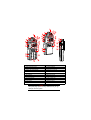
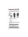
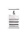
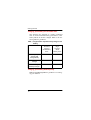
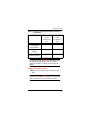
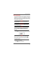
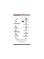
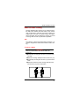
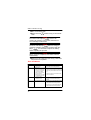
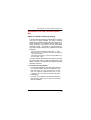
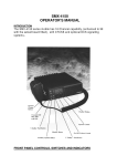
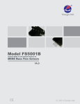
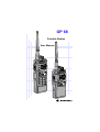
GP 68
Portable Radios
User Manual
#
1
7
2
8
10
9
3
1
7
2
8
4
11
5
12
10
9
2
1
3
13
6
4
5
11
14
12
15
18
13
6
10
16
14
15
23
18
22
17
23
19
22
#
21
20
1. On / Off and Volume Knob
13. Backspace Button
2. Channel Selector Knob
14. Left Scroll Button
3. Antenna Connector
15. Right Scroll Button
4. Toggle Light / Enter Button
16. Accessory Connector
5. Monitor Button
17. SCI Port
6. Push-To-Talk (PTT) Button
18. LCD Screen
7. Signal Button
19. Numeric Keypad
8. Squelch Button
20. Enable / Disable PTT ID Key
9. Low Power Button
21. Lock / Unlock Key
10. Scan / Nuisance Delete Button
22. Battery Pack
11. Microphone
23. Battery Latches
12. Speaker
NOTE
Keep this page open for easy reference as you go
through the user guide.
Copyright Information
The Motorola products described in this manual may
include copyrighted Motorola computer programs
stored in semiconductor memories or other mediums.
Laws in the United States and other countries preserve for Motorola certain exclusive rights for copyrighted computer programs, including the exclusive
right to copy or reproduce in any form the copyrighted
computer program. Accordingly, any copyrighted
Motorola computer programs contained in the Motorola products described in this instruction manual may
not be copied or reproduced in any manner without the
express written permission of Motorola. Furthermore,
the purchase of Motorola products shall not be
deemed to grant either directly or by implication,
estoppel, or otherwise, any license under the copyrights, patents, or patent applications of Motorola,
except for the normal non-exclusive, royalty fee license
to use that arises by operation of law in the sale of a
product.
© 1997 by Motorola, Inc.
All Rights Reserved.
Motorola Malaysia Sdn. Bhd. (Company No. 12631DE),
Bayan Lepas Free Industrial Zone, Phase III,
11900 Penang, Malaysia.
Printed in Malaysia.
Motorola, APC, Adaptive Power Control™
Technology and Channel Scan are trademarks of
Motorola, Inc.
Contents
Contents
Introduction . . . . . . . . . . . . . . . . . . . . . . . . . . . . . . . . . . 2
Packing Information. . . . . . . . . . . . . . . . . . . . . . . . . . . . 3
Knobs, Buttons, Connectors and Others . . . . . . . . . . . . 4
Getting Started . . . . . . . . . . . . . . . . . . . . . . . . . . . . . . . 8
Basic Operations . . . . . . . . . . . . . . . . . . . . . . . . . . . . . 14
Turning the Radio On . . . . . . . . . . . . . . . . . . . . . . . 14
Turning the Radio Off . . . . . . . . . . . . . . . . . . . . . . . 14
Adjusting the Volume . . . . . . . . . . . . . . . . . . . . . . . 14
Selecting a Channel . . . . . . . . . . . . . . . . . . . . . . . . 14
High / Low Power Output . . . . . . . . . . . . . . . . . . . . 15
Transmitting . . . . . . . . . . . . . . . . . . . . . . . . . . . . . . 15
Receiving . . . . . . . . . . . . . . . . . . . . . . . . . . . . . . . . 16
Additional Operations . . . . . . . . . . . . . . . . . . . . . . . . . 17
Display Backlight . . . . . . . . . . . . . . . . . . . . . . . . . . 17
PTT ID . . . . . . . . . . . . . . . . . . . . . . . . . . . . . . . . . . 17
Locking / Unlocking the Radio’s Function. . . . . . . . 18
Changing Squelch Modes. . . . . . . . . . . . . . . . . . . . 18
Setting Squelch Level . . . . . . . . . . . . . . . . . . . . . . . 20
Scan Operations . . . . . . . . . . . . . . . . . . . . . . . . . . . . . 21
DTMF Telephone Interconnect . . . . . . . . . . . . . . . . . . 23
Voice Selective Call (Optional) . . . . . . . . . . . . . . . . . . 27
Special Programming Mode (SPM) . . . . . . . . . . . . . . . 29
SPM Browse Menu . . . . . . . . . . . . . . . . . . . . . . . . . 30
LCD Segments and Indicators. . . . . . . . . . . . . . . . . . . 38
Alert Tone Indicators . . . . . . . . . . . . . . . . . . . . . . . . . . 39
Radio to Radio Cloning . . . . . . . . . . . . . . . . . . . . . . . . 41
Information For Safe, Efficient Operation . . . . . . . . . . 43
Recycling / Disposal of NiCd Batteries . . . . . . . . . . . . 46
Licensing & Service Information . . . . . . . . . . . . . . . . . 48
Troubleshooting. . . . . . . . . . . . . . . . . . . . . . . . . . . . . . 49
Accessories . . . . . . . . . . . . . . . . . . . . . . . . . . . . . . . . . 54
1
Introduction
Introduction
Congratulations on your purchase of a Motorola twoway radio. Your radio is a product of Motorola’s more
than 50 years of experience as a world leader in the
designing and manufacturing of communications
equipment. This radio offers superior quality, superior
performance, ultimate flexibility and years of reliable
and effective communications.
This radio incorporates the latest technology available
in two-way radio communications. The use of microcomputer technology makes changing radio characteristics such as operating frequencies and squelch
codes both economical and fast. Any computer
equipped dealer can easily reprogram your radio’s
operating characteristics.
The radio meets tough environmental demands while
providing cost-effective and reliable communications.
It meets established standards for low pressure, high
temperature, low temperature, temperature shock,
solar radiation, rain, humidity, salt fog, dust, vibration,
and shock. This radio also meets the Electronic Industry Association RS316B electrical and mechanical
specifications. The Motorola Accelerated Life Test
(ALT) assures that possible failures brought on by field
stress and abuse are identified and designed out of
your radio before it reaches your hands.
All of these features provide for better, yet more cost
effective communications for you.
Coverage of this User Guide
This user guide describes the operation of radios with
and without a keypad.
NOTE
#
2
The keypad symbol shown here indicates
that the feature is only available on radios
with keypads. This will be the convention
used throughout this user guide.
Packing Information
Packing Information
When you receive your packaged Motorola radio,
inspect the shipping carton for any signs of damage.
Next, remove and check the contents of the packing
case to be sure that all items ordered have been
included.
Fixed
Belt Clip
Antenna
Either
Or
#
Battery
Keypad Radio
Non-Keypad Radio
Standard Packaged Model Contents
• Keypad Radio or Non-Keypad Radio
• Battery
• Antenna
• Fixed Belt Clip
• User Manual
Inspect the equipment thoroughly. If any part of the
equipment has been damaged in transit, report the
extent of the damage to the transportation company
immediately.
NOTE
The radio as shipped accepts rechargeable NiCd
battery cell-pack (available as standard or high
capacity packs). Please refer to page 54 for a complete list of available accessories.
3
Knobs, Buttons, Connectors and Others
Knobs, Buttons, Connectors and Others
NOTE
The numbers in brackets below refer to the locations of the control buttons, knobs, etc. as shown in
the illustration on the inside front cover.
On / Off and Volume Knob (1)
Turns the radio on and off and adjusts the volume
level.
Channel Selector Knob (2)
➊ Selects the channel and squelch level.
➋ Changes the direction of scanning when the radio
is in scan mode.
Antenna Connector (3)
Connects antenna to the radio.
Toggle Light / Enter Button (4)
➊ Toggles display backlight status.
➋ Confirms user input (quick press).
Monitor Button (5)
Monitors the channel for activities (squelch is disabled).
Push-To-Talk (PTT) Button (6)
➊ Push to talk, release to listen.
➋ Press and hold when making DTMF dialling.
4
Knobs, Buttons, Connectors and Others
Signal Button (7),
SIG
A
➊ Toggles between Carrier, Coded (PL / DPL), and
Signalling Squelch modes.
➋ DTMF (Dual Tone Multiple Frequencies) digit ‘A’.
Squelch Button (8),
SQL
B
➊ Selects Carrier Squelch level.
➋ DTMF digit ‘B’.
Low Power Button (9),
LOW
C
➊ Toggles between high and low transmit power.
➋ DTMF digit ‘C’.
SCAN
Scan / Nuisance Delete Button (10),
D
N-DEL
➊ Enables / disables scanning (quick press).
➋ Deletes a Nuisance Channel (long press).
➌ DTMF digit ‘D’.
Microphone (11)
Used in the process of transmitting messages.
Speaker (12)
Used in the process of receiving messages.
Backspace Button (13),
When editing phone numbers and IDs, this key acts
as a backspace (rub-out) key.
5
Knobs, Buttons, Connectors and Others
Left Scroll Button (14),
Scrolls to the left when editing phone numbers and
IDs.
Right Scroll Button (15),
(non-keypad models)
M
ME
(keypad models)
➊ Scrolls to the right when editing phone numbers
and IDs.
➋ If held on power-up, radio enters into Special Programming mode.
➌ Stores / recalls phone numbers, phone access and
phone deaccess code (keypad models only).
Accessory Connector (16)
Connects accessories such as remote speaker
microphone or external handset to radio.
SCI Port (17)
Used to service and to clone the radio.
LCD Screen (18)
Displays information about the current state of the
radio (see “LCD Segments and Indicators” on
page 38).
NOTE
Items 19 to 21 are only applicable to keypad /
display models.
Numeric Keypad (19)
DTMF digits ‘0’ to ‘9’.
6
Knobs, Buttons, Connectors and Others
Enable / Disable PTT ID Key (20),
➊ Enables / disables PTT ID (long press).
➋ DTMF digit ‘#’.
➌ Pressing this key after MEM sends the programmed
phone deaccess code.
➍ Pressing this key immediately following
inserts a pause.
,
Lock / Unlock Key (21),
➊ Locks / unlocks the keypad (long press).
➋ DTMF digit ‘∗’.
➌ Pressing this key after
phone access code.
M
ME
sends the programmed
Battery Pack (22)
Power supply to the radio.
Battery Latches (23)
For attaching battery tray / pack to the radio.
7
Getting Started
Getting Started
Attaching and Removing the Antenna
Attaching
➊ Fasten the antenna to the radio by placing the
threaded end of the antenna into the Antenna Connector (3).
➋ Rotate the antenna clockwise until tight.
Removing
• Turn the antenna in an anti-clockwise direction until
it disengages from the radio.
Attaching and Removing the Belt Clip
Attaching
➊ Align mounting rails of the radio with the grooves of
belt clip.
➋ Slide belt clip downwards until it clicks into place.
Removing
➊ Insert the end of a key between the release tab
and the back surface of the radio.
➋ Lift the release tab; slide the belt clip upwards.
Installing and Removing Batteries
Installing
➊ Align the Battery Pack (22) with the back of the
radio.
➋ Slide the Battery Pack (22) into place.
8
Getting Started
Removing
➊ Release the Battery Latches (23).
➋ Slide the Battery Pack (22) away from the radio.
Charging NiCd Battery Pack
Before using your radio with a rechargeable (NiCd)
battery, you must charge the battery.
WARNING
DO NOT attempt to charge your radio if you are
using alkaline batteries. Doing this may cause the
batteries to leak or explode, leading to severe skin
burns or eye injuries.
IMPORTANT
Transmitting a message while your radio is charging can cause the radio or the charger to operate
improperly. DO NOT transmit when your radio is
charging.
NOTE
Your radio may take twice as long to charge if it is
not turned off during charging.
9
Getting Started
Charging your Battery for the FIRST time
New batteries are supplied in a totally uncharged
state. To ensure maximum battery performance, a new
battery MUST be FULLY charged. Refer to the following table for guidelines.
Table 1: Length of time required to fully charge a new
battery
Standard
Capacity
NiCd Battery
Pack
High
Capacity
NiCd
Battery Pack
Wall Charger (with/
without Wall
Charger Base)
16 hours
20 hours
Standard Desktop
Charger
16 hours
16 hours
Quick Charge
Desktop Charger
16 hours
16 hours
Charging your Battery Subsequently
Refer to the following table for guidelines on recharg-
ing your batteries.
10
Getting Started
Table 2: Length of time required to fully recharge a
used battery
Standard
Capacity
NiCd Battery
Pack
High
Capacity
NiCd Battery
Pack
Wall Charger (with/
without Wall
Charger Base)
10 hours
20 hours
Standard Desktop
Charger
10 hours
10 hours
Quick Charge
Desktop Charger
3 hours
3 hours
NOTE
A battery that is left unused for several months will
be completely discharged. In this case, follow
guidelines in Table 1 on page 10 to recharge the
battery.
Charging with Wall Charger
➊ Make sure the battery pack is attached to the
radio.
NOTE
With the Charger Base, the battery can be charged
when connected or not connected to the radio.
➋ Turn the radio off (if it is turned on).
11
Getting Started
If not using the Charger Base:
➌ Lift the dust cover covering the Accessory Connector (16).
➍ Insert one end of the Wall Charger into the lower
port of the Accessory Connector (16), and the
other into an electrical outlet.
If using the Charger Base:
➌ Insert the radio / battery into the charging docket.
➍ Refer to Table 1 and 2 on pages 10 and 11 for an
estimation of the duration involved for charging the
battery pack.
➎ Unplug the Wall Charger from the radio when
charging is complete.
NOTE
The LED on the Wall Charger is lit (red) continuously during charging.
Charging with Desktop Charger
NOTE
With Desktop Chargers, the battery can be charged
when connected or not connected to the radio.
➊ Place the Charger Insert into the Desktop Charger.
12
Getting Started
➋ Insert the radio / battery into the charging docket.
If using the Quick Charge Desktop Charger:
➊ Press the Quick Charge button.
➋ Refer to Table 1 and 2 on pages 10 and 11 for an
estimation of the duration involved for charging the
battery pack.
➌ Remove the radio / battery from the charger when
charging is complete.
NOTE
The LED on the charger lights up continuously during charging. For the Standard Desktop Charger, it
is red for the whole charging period. For the Quick
Charge Desktop Charger, it changes from yellow
(before charging begins) to red (during charging) to
green (when charging is completed).
CAUTION
The Quick Charge Desktop charger runs on a 3hour timer which begins counting each time you
press the Quick Charge button. Removing the battery or radio from the charger before the battery is
fully charged, or removing and replacing battery /
radio repeatedly during charging, and then pressing the Quick Charge button again can overcharge
or damage the battery. Press the Quick Charge button only when the battery needs to be fully
charged.
13
Basic Operations
Basic Operations
Turning the Radio On
• Rotate the On / Off and Volume Knob (1) clockwise to turn the radio on.
Turning the Radio Off
• Rotate the On / Off and Volume Knob (1) anticlockwise until a click is heard to turn the radio off.
Adjusting the Volume
• Rotate the On / Off and Volume Knob (1) clockwise to increase your radio’s volume level, or anticlockwise to decrease it.
NOTE
To do an initial setting of the volume, press and
hold the Monitor Button (5) until the background
noise is heard. Continue holding the Monitor Button (5) while adjusting to the desired volume.
Selecting a Channel
The radio is preconfigured by the dealer for use with
your communications system. Up to 20 programmed
channels may be available. Each channel consists of a
frequency pair - one transmit frequency and one
receive frequency.
• Rotate the Channel Selector Knob (2) to the
desired channel.
The LCD Screen (18) shows the channel that the
radio is operating on.
14
Basic Operations
NOTE
Empty memory / unprogrammed channels are not
displayed.
High / Low Power Output
LOW
• Press C to toggle between high and low power
output levels.
NOTE
The indicator LOW lights up on the LCD Screen
(18) when the radio is operating in low power mode.
NOTE
High power mode can improve the clarity of voice
activity in areas where signals are weak while low
power mode extends battery life.
Transmitting
➊ Select the desired channel by rotating the Channel Selector Knob (2).
➋ Press and hold the Monitor Button (5), and listen
for channel activity.
➌ If the channel is clear, press the Push-To-Talk
(PTT) Button (6) and speak clearly into the Microphone (11) (see “Information For Safe, Efficient
Operation” on page 43 for more information).
TX
15
Basic Operations
NOTE
Unless disabled (‘dot’ indicator flashes on the LCD
Screen (18)), PTT ID tones are heard as they are
being transmitted (see “PTT ID” on page 17). You
can start your conversation when the tones end.
NOTE
The ‘TX’ indicator lights up on the LCD Screen (18)
when the Push-To-Talk (PTT) Button (6) is pressed.
IMPORTANT
Whenever you transmit a message, you are using
the resources of the transmitting channel. Speaking
for long periods of time would deprive others from
using that channel.
NOTE
The maximum duration for transmission is determined by the value of the Time-Out-Timer (see “Editing the Time-Out Timer Duration” on page 33).
Once you reach the time limit, a Time-Out Timer Alert
tone is sounded, and the transmission is cut off.
Receiving
• If the Push-To-Talk (PTT) Button (6) is pressed,
release it and listen for incoming messages.
NOTE
Make sure the volume level is set properly, or else
you may receive a message but are unaware about it.
16
Additional Operations
Additional Operations
Display Backlight
• Press the Toggle Light / Enter Button (4) to turn on /
off the backlight.
NOTE
To conserve power, the backlight is programmed to
automatically turn off after 5 seconds.
NOTE
Pressing either the Push-To-Talk (PTT) Button (6)
or the Monitor Button (5) has no effect on the backlight.
PTT ID
If programmed, the radio transmits a DTMF identification code (unit ID), indicating which portable is in operation.
During a conversation, the code is normally sent only
on the initial Push-To-Talk (PTT) Button (6) press
(unless PTT ID has been disabled). The ‘TX’ indicator
lights for the duration of the PTT ID. If there is no PTT
or receive activity for 7 seconds, or if you change the
channel (or scan resumes), the PTT ID is once again
transmitted on the next Push-To-Talk (PTT) Button (6)
press.
• Press and hold
to enable / disable PTT ID.
#
NOTE
Upon pressing
, you will hear a beep. Hold the
button down until you hear a second beep, indicating that the PTT ID status has been changed.
When PTT ID is disabled, the ‘dot’ indicator flashes
on the display (To enable / disable PTT ID on nonkeypad radios, please contact your dealer).
17
Additional Operations
Locking / Unlocking the Radio’s Function
#
Locking the radio will disable all buttons except
the Toggle Light / Enter Button (4), Monitor Button (5), Push-To-Talk (PTT) Button (6) and
.
Pressing a locked button will result
being
shown on the LCD Screen (18).To lock / unlock
the radio:
• Press and hold
beeps are heard.
(for about 2 seconds) until two
NOTE
The lock / unlock status remains unchanged even
when the power is turned off.
Changing Squelch Modes
Squelch acts as a kind of filtering system which helps
to control the amount of signals the radio receives.
Configuring the radio to receive only the desired signals minimizes interference from other users of the
same channel.
This radio supports Carrier Squelch (CSQ), Coded
Squelch - Tone Private-Line (PL), Digital Private-Line
(DPL) and Signalling Squelch - Voice Selective Call
(SelCall) operations on a per channel basis.
Carrier Squelch transmission allows all radios tuned to
the selected receive channel (frequency) to hear the
conversation. Coded Squelch transmission only allows
radio(s) having the same PL / DPL code on the
selected receive channel (frequency) to hear the conversation. Signalling Squelch transmission can only be
decoded by radios with the valid Voice Selective Call
(SelCall) identification code (see “Voice Selective
Call (Optional)” on page 27).
18
Additional Operations
NOTE
To perform Signalling Squelch (SelCall) operation,
the radio must be equipped with an optional DTMF
Decode board.
To temporarily override the default receive squelch
mode for the channel:
SIG
• Press A to change between Carrier (CSQ),
Coded (PL / DPL) and Signalling (SelCall) squelch
modes.
CTCSS
NOTE
The ‘CTCSS’ indicator lights up continuously when
the radio is operating in Coded (PL / DPL) mode,
flashes when operating in Signalling (SelCall) mode
and is not displayed when operating in Carrier
(CSQ) mode.
NOTE
To select Coded Squelch mode while receiving, the
channel must be pre-programmed with a receive
PL / DPL code. The transmit squelch mode is fixed
and cannot be changed by the user. The squelch
mode is reset to the pre-programmed receive squelch
mode for the channel whenever you change channels.
NOTE
Whenever you switch from one channel to the other,
the default squelch mode of the new channel takes
effect.
19
Additional Operations
Setting Squelch Level
An open (low) squelch level sets the threshold for the
receiving signal strength to be low. This means that
the radio would receive a great variety of signals, both
weak and strong. A tighter (higher) squelch level
raises the threshold, thus filtering weak signals and
only accepting the stronger ones. To set the squelch
level:
➊ Press
SQL
B
.
➋ Rotate the Channel Selector Knob (2) to select the
desired squelch level.
➌ Press the Toggle Light / Enter Button (4) (or any
other button) momentarily to adopt the selected
squelch level and return to normal operating mode.
IMPORTANT
The radio automatically adopts the new squelch
level and returns to normal operation after 5 seconds of inactivity.
NOTE
If you reach the upper (‘15’) or lower (‘00’) limit of
the squelch range, the squelch level does NOT
wrap around to the opposite limit but remains
where it is.
20
Scan Operations
Scan Operations
Scan operation tells the radio to monitor a list of preprogrammed channels (see “Editing the Channel
Scan List” on page 31). When there are some activities at a particular channel, the radio stops scanning
and changes to that channel.
NOTE
Each channel is given the same scan priority i.e.
non-priority scan.
IMPORTANT
The radio will not recall the scan state if it is powered off while scanning.
NOTE
Channels may be temporarily removed from the
scan list using the Nuisance Channel Delete feature (see “Deleting a Nuisance Channel” on
page 22).
SCAN
• Press
D
N-DEL
momentarily to begin channel scanning.
SCAN
NOTE
While scanning is in progress, the Home Channel
SCAN
D
(the channel the radio was active at before N-DEL
was pressed) is displayed until activity is received
on another channel.
To stop the scan operation:
SCAN
• Press
D
N-DEL
again momentarily.
21
Scan Operations
NOTE
While scanning is in progress, if the Push-To-Talk
(PTT) Button (6) is pressed, the radio would transmit on the Home Channel. However, if the radio has
stopped scanning and is receiving signals from a
particular channel, all transmit and receive activity
would be performed on that channel. Once the
scan locks at a channel, a short “hang time” (about
7 seconds) occurs.This is to allow a response to be
made before scanning resumes.
Deleting a Nuisance Channel
When the radio is scanning, it would stop at any channel with activity. A channel that generates unwanted
signals continuously is called a Nuisance Channel. To
temporarily remove the channel from the scan list:
SCAN
D
• Press and hold N-DEL
(for about 2 seconds) while
scan locks on the Nuisance Channel.
NOTE
Two medium-pitched “beeps” are sounded, indicating that the radio has temporarily removed the Nuisance Channel from its scan list.
NOTE
If an attempt to perform a Nuisance Channel Delete
on the Home Channel is made, an Invalid Button
Press alert tone will sound and no action will be
taken. This ensures the availability of a channel
when the radio is used to transmit.
IMPORTANT
To add a deleted channel back into the scan list,
exit and reenter the scan function or restart the
radio.
22
DTMF Telephone Interconnect
DTMF Telephone Interconnect
#
Dual Tone Multiple Frequency (DTMF) tones are
encoded by the radio to dial into (access) the
landline telephone network and return (deaccess) to
conventional radio operation.
Once the telephone network has been accessed,
phone numbers can be dialled either manually or from
memory. The keypad provides support for DTMF digits
0 to 9, and the characters A, B, C, D, ∗ and #.
NOTE
The radio is capable of storing a maximum of 9 preprogrammed phone numbers (up to 12 digits each).
Placing a Telephone Call
To place a call:
➊ Press and hold the Push-To-Talk (PTT) Button (6).
➋ Dial the access code manually using the DTMF
keys or press MEM then
to send the preprogrammed access code.
➌ Release the Push-To-Talk (PTT) Button (6) and
wait for a dial tone.
➍ Press and hold the Push-To-Talk (PTT) Button (6)
and either manually dial the telephone number or
press MEM and the phone number location that
stores the preprogrammed telephone number.
➎ Press the Push-To-Talk (PTT) Button (6) to talk;
release to listen.
23
DTMF Telephone Interconnect
NOTE
If you press a phone number location which has not
been programmed, the radio will sound an Invalid
Button Press tone and no further action is taken.
To hang up:
➊ Press and hold the Push-To-Talk (PTT) Button (6).
➋ Manually dial the deaccess code or press MEM
then
to send the preprogrammed deaccess
code.
Last Number Redial
Manually dialled phone numbers (up to 16 digits long)
are stored in numeric location “0” for quick redial capabilities.They are sent exactly as preprogrammed telephone numbers are. After you receive a dial tone:
• Press and hold Push-To-Talk (PTT) Button (6), then
press MEM and
.
NOTE
Last Number Redial only stores manually dialled
numbers and NOT preprogrammed telephone numbers. The number set is stored in phone location 0
until the radio is turned off or until another DTMF
sequence is manually dialled.
NOTE
If you attempt to perform a last number redial where
no manual numbers have yet been dialled since
radio power-up, the radio will sound an Invalid Button Press tone.
24
DTMF Telephone Interconnect
Storing a Phone Number
A maximum of 9 telephone numbers (up to 12 digits
each) can be stored into the radio memory. Each
phone number is stored and recalled via a unique
number on the keypad in the range of 1 to 9. The following procedure can also be used to store the access
/ deaccess codes (up to 8 digits each):
➊ Press and hold MEM until you hear a second Valid
Button Press tone (takes about 2 seconds).
(flashing cursor)
➋ Enter a phone number location (in the range of 1 to
9) to store a phone number or press
to store
the access code or
to store the deacess code.
➌ Enter the phone number (up to 12 digits long), or
access / deaccess code (up to 8 digits long).
NOTE
Valid digits are DTMF digits 0 to 9, the characters
A, B, C, D, ∗ and #, and pause digits.
NOTE
Pause digit (
)causes the radio to wait in
between transmission of the digits programmed
before and after it. One or more pause digits can be
entered between successive digits of the phone
number (or access / deaccess code). When a
pause digit is successfully entered, two beeps are
heard; the display changes from ‘A’ to ‘-’. Pause
digits placed at the end of a phone number are not
remembered by the radio.
25
DTMF Telephone Interconnect
NOTE
If you make a mistake, press
to scroll the cursor to the left and erase the incorrect entry. To view
a numeric sequence of more than 6 digits, press
or MEM to scroll the cursor to the left or right.
NOTE
All undefined digits are represented by underscores
on the LCD Screen (18). A flashing ‘_’ indicates the
position for the next number entry. If you reach the
maximum number of entries, the cursor position is
under the last digit. An Invalid Button Press tone
will sound if you attempt to enter more than the
maximum number of digits.
➍ Press the Toggle Light / Enter Button (4) to store
the phone number (or access / deaccess code) into
the designated location and return to normal operation.
Displaying a Stored Phone Number
➊ Press MEM momentarily in the receive mode. A
Valid Button Press tone is heard.
➋ Enter a one-digit phone number location (in the
range of 1 to 9) to view the stored phone number or
press
/
/ to view the access / deaccess
code or press
to review the last number
dialled.
NOTE
If the keypad entry is valid, the LCD Screen (18)
displays the first 6 digits of the stored phone number or code. For number sequences more than 6
digits, after 2 seconds the number begins autoscrolling to the left in 1 second increments until the
last digit is displayed. If the selected phone location
is empty, an Invalid Button Press tone is heard.
26
Voice Selective Call (Optional)
Voice Selective Call (Optional)
To support Voice Selective Call (SelCall) operation, the
radio must be equipped with an optional DTMF
Decode board.
NOTE
For more information about the availability of this
option, contact your dealer.
If your radio is equipped with the Voice Selective Call
option, your radio can be called individually by another
user, or as part of a small group.
Receiving a Voice Selective Call
When the radio decodes a Voice Selective Call, the
LCD Screen (18) indicates the type of SelCall message being received:
Individual Call
Group Call
ALL Call
NOTE
The radio will give an alert tone when it successfully decodes a Voice Selective Call. If either Selective Call Tone Status or Alert Tone Volume is set to
“OFF” (see page 33 and 35 ), no tone is heard.
For an Individual Call, the radio automatically transmits an Acknowledgement message back to the calling radio, if an Acknowledgement ID has been
preprogrammed by the dealer.
27
Voice Selective Call (Optional)
When the radio decodes a Voice Selective Call, it
enters the carrier squelch mode for a period of time. If
there is no receive activity, the radio resumes the
selected squelch mode and the LCD Screen (18)
reverts to the appropriate receive mode display.
IMPORTANT
If the Channel Selector Knob (2) is rotated or any
buttons pressed while the SelCall signal is in
progress, the SelCall message disappears and the
Selective Call is lost.
Sending a Voice Selective Call
#
➊ Press and hold the Push-To-Talk (PTT) Button (6).
➋ Dial the required Selective Call ID.
➌ Release the Push-To-Talk (PTT) Button (6).
NOTE
For an Individual Call, the radio indicates that the
call was received by generating two short ringing
tones.
28
Special Programming Mode (SPM)
Special Programming Mode (SPM)
The Special Programming mode (SPM) allows you to
edit all user-modifiable parameters within your radio,
such as the Channel Scan list, Phone Access / Deaccess codes, and Alert Tone Settings. Certain parameters (such as the Selective Call Tone Status) are only
accessible with the installation of an option board.
Upon entry to the Special Programming mode, the
radio initiates the SPM Browse menu which provides
you with a menu of available parameters and their current settings.
Entering SPM
➊ Turn the radio off (if it is on).
➋ Turn the radio on while holding
(or MEM ).
Keep holding this button until a SPM start-up tone
sounds.
NOTE
At power-up, all display segments light up for about
2 seconds. If successful, the LCD Screen (18) displays
.
NOTE
If the battery level is low, the display indicates
and the ‘BATT’ indicator flashes. The radio
also sounds a Low Battery alert tone. Turn off the
radio and replace or recharge the battery.
Exiting SPM
• Turn off the radio to exit SPM.
29
Special Programming Mode (SPM)
SPM Browse Menu
(Anti-Clockwise Rotation)
“Beep”
(Clockwise
Rotation)
FIRST
ITEM
Edit Channel Scan List
Set Accessory Option
*Edit Phone Access Code
*Edit Phone Deaccess Code
Set Battery Type
xxx†
Edit Time Out Timer
Set Battery Saver Status
§
Set SelCall Tone Status
Alert Tone Volume
Set Sidetone Status
* Only applicable for keypad models.
§
Only displays with option board installed.
†xxx represents
,
,
,...,
.
30
Special Programming Mode (SPM)
Editing SPM Parameters
Editing the Channel Scan List
➊ In SPM, rotate the Channel Selector Knob (2) to
select the Edit Channel Scan List (
) menu
item.
➋ Use
or
(or
channels (01 to 20).
M
ME
) to scroll through the
NOTE
The channel scan list does not wrap around to the
opposite end of the list. Instead, an Invalid Button
Press tone sounds when you have reached the
upper or lower limit of the list.
NOTE
A flashing channel number indicates that the channel is excluded from the scan list.
➌ Press the Toggle Light / Enter Button (4) to toggle
the status of a channel i.e. being included or
excluded from the scan list.
NOTE
A Valid Button Press tone sounds when the new
setting is stored.
➍ To exit this menu, select another menu item by
turning the Channel Selector Knob (2).
Editing the Phone Access / Deaccess Codes
#
➊In SPM, rotate the Channel Selector Knob (2) to
the Edit Phone Access (
) or Edit Phone
Deaccess (
) menu.
➋ Press
or
M
ME
to enter the edit mode.
31
Special Programming Mode (SPM)
NOTE
The LCD Screen (18) displays the current access /
deaccess code. For a code which exceeds the 6digit display length, the rightmost digit flashes to
indicate that more digits exist on the right.
➌ Enter the new access / deaccess code (up to 8 digits) using any of the numeric keys, A, B, C, D,* and
#.
NOTE
The LCD Screen (18) shows the new digits as they
are being entered. When the cursor is flashing
under a digit, the maximum number has been
entered. Use
or MEM to scroll through the
existing code and
to erase unwanted digits.
NOTE
Pause digit (
)causes the radio to wait in
between transmission of the digits programmed
before and after it. One or more pause digits can be
entered between successive digits of the phone
access / deaccess codes. When a pause digit is
successfully keyed, two beeps are heard; the display changes from ‘A’ to ‘-’. Pause digits placed at
the end of a phone number are not remembered by
the radio.
➍ Press the Toggle Light / Enter Button (4) to store
the new code and return to SPM Browse Menu.
NOTE
A Valid Button Press tone sounds when the new
setting is stored.
➎ To abort data entry, select another menu item by
turning the Channel Selector Knob (2) or wait until
32
Special Programming Mode (SPM)
the edit mode time-out (after 5 seconds of inactivity).
Editing the Time-Out Timer Duration
➊ In SPM, rotate the Channel Selector Knob (2) to
the Edit Time Out Timer (
xxx) menu.
NOTE
xxx represents one of
,
,
, .....,
. The
default display of
shows the time-out timer
setting of one minute. If the display shows
,
this indicates that the time-out timer is disabled.
This means that there is no limit on the transmit
time.
➋ Use
status.
or
(or
M
ME
) to change the current
CAUTION
The new setting is stored immediately.
➌ To exit this menu, select another menu item by
turning the Channel Selector Knob (2).
Setting the Selective Call Tone Status
Selective Call alert tones give an audible indication of
receipt of a Voice Selective Call (SelCall). If disabled,
the alert tones do not sound when Voice Selective Call
messages are received by the radio.
33
Special Programming Mode (SPM)
NOTE
Setting the Alert Tone Volume to off disables all
tones regardless of the setting of this parameter
(see “Setting the Alert Tone Volume” on
page 35).
➊ In SPM, rotate the Channel Selector Knob (2) to
the Set SelCall Tone Status (
or
)
menu.
or
➋ Use
and Off.
(or
M
ME
) to toggle between On
CAUTION
The new setting is stored immediately.
➌ To exit this menu, select another menu item by
turning the Channel Selector Knob (2).
Setting the Sidetones Status
If transmit sidetones is disabled, DTMF sidetones
such as phone number and PTT ID sidetones are not
heard during transmission.
➊ In SPM, rotate the Channel Selector Knob (2) to
the Set Sidetones Status (
or
) menu.
or
➋ Use
and Off.
(or
M
ME
) to toggle between On
CAUTION
The new setting is stored immediately.
➌ To exit this menu, select another menu item by
turning the Channel Selector Knob (2).
34
Special Programming Mode (SPM)
Setting the Alert Tone Volume
➊ In SPM, rotate the Channel Selector Knob (2) to
the Alert Tone Volume (
or
) menu.
or
➋ Use
and Off.
(or
M
ME
) to toggle between On
NOTE
When
is chosen, the alert tone volume follows the volume control setting (see “Adjusting
the Volume” on page 14).
CAUTION
The new setting is stored immediately.
➌ To exit this menu, select another menu item by
turning the Channel Selector Knob (2).
Setting the Battery Saver Status
When enabled, the Battery Saver feature increases
the amount of time between battery replacement or
charging. Battery power is conserved by turning off the
receiver circuitry, except for periodic checks for carrier
activity.
➊ In SPM, rotate the Channel Selector Knob (2) to
the Set Battery Saver Status (
- Off, or
- Normal, or
- Enhanced) menu.
or
➋ Use the
three options.
(or
M
ME
) to scroll through the
CAUTION
The new setting is stored immediately.
35
Special Programming Mode (SPM)
➌ To exit this menu, select another menu item by
turning the Channel Selector Knob (2).
NOTE
The Battery Saver feature is not active during channel scanning, when the Push-To-Talk (PTT) Button
(6) is pressed, or when the radio is receiving a signal.
Setting the Battery Type
➊ In SPM, rotate the Channel Selector Knob (2) to
the Set Battery Type (
- Alkaline (standard
battery) or
- NiCd (rechargeable battery))
menu.
or
➋ Use the
three options.
(or
M
ME
) to scroll through the
CAUTION
The new setting is stored immediately.
➌ To exit this menu, select another menu item by
turning the Channel Selector Knob (2).
IMPORTANT
The Battery Type must be correctly set for Low Battery Alert to perform accurately.
Setting the Accessory Sense Option
This menu item determines the type of accessory in
use by the radio (if any), such as a headset, earpiece,
or speaker microphone. There are three options available: Autosense, Headset Only and Speaker Microphone Only.
36
Special Programming Mode (SPM)
➊ In SPM, rotate the Channel Selector Knob (2) to
the Set Accessory Option (
- Autosense or
- Speaker Microphone Only or
Headset Only) menu.
or
➋ Use the
three options.
(or
M
ME
) to scroll through the
CAUTION
The new setting is stored immediately.
➌ To exit this menu, select another menu item by
turning the Channel Selector Knob (2).
NOTE
When Autosense is selected, the radio checks the
accessory jack to see what type of accessory is
connected. When Headset Only is selected, the
radio supports only an earpiece or headset, and all
external PTT inputs are ignored. When Speaker
Microphone Only is selected, the radio assumes
that an accessory with an external PTT switch will
be used to transmit voice. The radio’s internal
microphone will not transmit voice whenever an
accessory is connected.
IMPORTANT
The radio should be turned off when an audio
accessory with a microphone is connected to the
radio. This is to ensure the proper operation of the
Push-To-Talk (PTT) Button (6).
37
LCD Segments and Indicators
LCD Segments and Indicators
TX
LOW
CTCSS
BATT
SCAN
SAVE
SIGNAL
Indicators
TX - Lights up when radio is transmitting.
LOW - Lights up when radio is in low transmit power
mode.
CTCSS - Lights up continuously for Coded Squelch
mode; Off for Carrier Squelch mode; Flashes for Signalling Squelch mode (if available).
SCAN - Flashes when radio is scanning; Lights up
continuously when scan is suspended.
BATT - Flashes when battery voltage is low.
SAVE - Flashes quickly when Normal Battery Saver
mode is enabled; flashes slowly when Enhanced Battery Saver mode is enabled; nothing displayed when
Battery Saver is disabled.
Indicators with Segments
SIGNAL - uses six bar segments to indicate the relative receive (Rx) signal strength. SIGNAL lights up
upon receiving a Rx signal strength greater than 10 dB
SINAD. As the signal strength increases, additional
bar segments light up, starting from the left-most bar
segment.
38
Alert Tone Indicators
Alert Tone Indicators
Successful Power-Up
A short, high-pitched tone when the radio is turned on
indicates that the radio has passed its power-up selftest and is ready for use.
Unsuccessful Power-Up
A short, low-pitched tone immediately following the
Successful Power-Up tone indicates that the radio has
detected an error and has failed to power-up properly.
Valid Button Press
A short, high-pitched tone indicates that the last button
pressed was valid.
Invalid Button Press
A short, low-pitched tone indicates that the last button
pressed was invalid.
Low Battery
Three low-pitched tones indicate a low battery condition.
DTMF Sidetones
Each DTMF tone is heard as it is transmitted.
Time-Out Timer Alert
A low-pitched continuous tone indicates that your
present transmission has been disabled.
39
Alert Tone Indicators
Individual Selective Call Decode
Two short “ringing” tones indicate that an Individual
Selective Call has been decoded by the radio. The
radio automatically sends an Acknowledgment ID.
Acknowledgment ID Decode
A short “ringing” tone indicates that a correct Acknowledgment ID has been decoded by the radio.
Group and All Call Selective Call Decode
Two medium-pitched tones indicate that a Group or All
Call Selective Call has been decoded by the radio.
Cloning Mode Start-up
A short “ringing” tone indicates entry into the Cloning
mode.
Nuisance Channel Delete
During channel scanning, two medium-pitched tones
indicate that an unwanted channel has been temporarily deleted from the scan list.
40
Radio to Radio Cloning
Radio to Radio Cloning
Cloning duplicates the contents of one radio (the master radio) into another (the slave radio). Only current
radio configuration, channels and phone numbers are
copied from one radio to another. Tuning and alignment information are not affected by cloning. You need
a cloning cable in order to perform this operation.
SCI
SCI stands for Serial Communications Interface. It is
used to configure the radio and for radio to radio cloning.
To Clone a Radio
CAUTION
Make sure both master and slaves radios are
turned off.
➊ Lift the flap covering the SCI Port (17) of the master radio.
➋ Insert the cloning cable jack into the SCI Port (17).
➌ Lift the flap covering the SCI Port (17) of the slave
radio.
➍ Insert the other end of the cloning cable jack into
the SCI Port (17) of the slave radio.
41
Radio to Radio Cloning
➎ Turn on the slave radio.
SIG
➏ Press and hold A before turning on the master
radio.
NOTE
The master radio displays
on the LCD
Screen (18) if cloning can proceed, otherwise an
error message will be shown.
NOTE
The slave radio displays
while it is being programmed. If battery level is low, the slave radio displays
. You will need to replace the battery
before repeating the process.
NOTE
When cloning is completed, both radios will reset
automatically.
➐ Disconnect the radios from the cloning cable when
the process is completed.
Error Conditions
Error Message
Err.01
Err.02
Problem
Incompatible software
options error.
Solution
Cloning from the master radio to the
slave radio cannot be performed.
Timeout error
a. The cloning cable con- a. Check the cloning cable connection and
nection is not properly
also verify that the slave radio is turned
connected or slave
on.
radio is not turned on.
b. Communication
b.
Check the cloning connection and all
between the two radios
other connections.
is disrupted during the
cloning process.
Err.03
Master radio
checksum error
Err.04
No Programmed Chan- a. If this occurs on the slave radio, repeat
nels Error
cloning procedure. If it persists, the
radio must be serviced by a dealer.
Although the master radio may still
function, it should be serviced by a
dealer.
b. If this occurs on the master radio, the
radio must be serviced by a dealer.
42
Information For Safe, Efficient Operation
Information For Safe, Efficient Operation
Exposure To Radio Frequency Energy
In August 1996 the Federal Communications Commission (FCC) adopted updated RF energy exposure
guidelines for wireless products regulated by the FCC.
Those guidelines are consistent with the safety standards* previously set by both U.S. and international
standards bodies. The design of your Motorola twoway radio complies with the FCC guidelines and these
standards.
*American National Standards Institute (C95.1 - 1992);
*National Council on Radiation Protection and Measurements (NCRP-1986);
*International Commission on Non-Ionizing Radiation Protection (ICNRP- 1986)
To assure optimal radio performance and to insure that
exposure to RF energy is within the guidelines in the
above standards, the following operating procedures
should be observed:
For Portable Two-way Radios:
• For hand held operation, the radio should be held
in a vertical position with the microphone one to
two inches (2.5 to 5 cm) away from the mouth,
and the antenna should be kept one to two
inches (2.5 to 5 cm) from the head or body when
transmitting.
• For body worn operation, the antenna should be
kept at least one inch (2.5 cm) from the body
when transmitting.
43
Information For Safe, Efficient Operation
Electromagnetic Interference/compatibility
Nearly every electronic device is susceptible to electromagnetic interference (EMI) if inadequately
shielded, designed or otherwise configured for electromagnetic compatibility.
• Turn your radio OFF in any facilities where
posted notices instruct you to do so. Hospitals or
health care facilities may be using equipment that
could be sensitive to external RF energy.
• Turn your radio off when on board aircraft when
instructed to do so. Any use of the radio must be
in accordance with Federal Aviation Administration (FAA) and FCC regulations or crew instructions.
CAUTION
• Do not use the radio with a damaged antenna. If
a damaged antenna comes into contact with the
skin, a minor burn may result.
• All batteries can cause property damage, injury
or burns if a conductive material such as jewelry,
keys or beaded chains touches exposed terminals. The material may complete an electrical circuit (short circuit) and become quite hot.
Exercise care in handling any charged battery,
particularly when placing it inside a pocket, purse
or other container with metal objects.
Potentially Explosive Atmospheres
Areas with potentially explosive atmospheres are
often, but not always, clearly marked. They include
fuelling areas such as below deck on boats, fuel or
chemical transfer or storage facilities; areas where the
air contains chemicals or particles, such as grain,
dust, or metal powders; and any other area where you
44
Information For Safe, Efficient Operation
would normally be advised to turn off your vehicle
engine.
WARNING
• Turn your radio OFF when in any area with a
potentially explosive atmosphere, unless it is a
type especially qualified for such use (for example, FMRC Approved). Sparks in such areas
could cause an explosion or fire resulting in
bodily injury or even death.
• Do not replace or charge batteries in a hazardous atmosphere. Contact sparking may occur
while installing or removing batteries and cause
an explosion.
Blasting Caps And Areas
WARNING
To avoid possible interference with blasting operations, turn your radio OFF near electrical blasting
caps or in a “blasting area” or in areas posted: “Turn
off two-way radio”. Obey all signs and instructions.
For Vehicles With An Air Bag
WARNING
An air bag inflates with great force. Do not place
objects, including portable or mobile two-way
radios, in the area over the air bag or in the air bag
deployment area. If improperly installed or placed
wireless equipment is in the air bag deployment
area and the air bag inflates, serious injury could
result.
45
Recycling / Disposal of NiCd Batteries
Recycling / Disposal of NiCd Batteries
The U.S. Environmental Protection Agency (EPA) classifies used NiCd batteries as hazardous waste, unless
certain exemptions apply.
At the end of your battery’s useful life, it can be recycled. However, recycling facilities may not be available
in all areas. Under various state or local laws, such
batteries must be recycled or disposed of properly,
and cannot be dumped in landfills or incinerators.
Motorola fully endorses and encourages the recycling
of NiCd batteries. The following is a list of recycling
facilities around the world, where you can ship your
NiCd batteries post paid to be recycled:
United States
INMETCO
P.O. Box 720
245 Porteville Road
Ellwood City, PA 16117
Tel:(412) 758-5515
Fax:(412) 758-9311
Europe
S.N.A.M.
Rue de la Garenne
Z.I. Chesnes Tharabie -BP733
Saint Quentin Fallavier
38297 La Verpilliere Cedex,
France
Tel: 033-74-94-59-85
Fax: 033-74-94-13-18
Asia
Hanil Metal Recycle Co. Ltd.
2404 Palryong-dong
Changwon-Shi
Kyongsangnam-Do, Korea
Tel: 082-551-93-1911
Fax: 082-551-96-0050
46
Recycling / Disposal of NiCd Batteries
Japan
Marubeni Co.
Head Office/Attn. B6B2
4-2 Ohtemachi 1-Choma
Ciyoda-Ku, Tokyo, Japan
Nippon Recycle Ctr., Corp.
6-3-19, Nishitamma, Kita-Ku
Osaka, 530, Japan
Tel: 081-6-311-9071
Fax: 081-311-0949
You should consider the methods of collecting, labeling, and shipping used NiCd batteries. Consult your
federal, state, or local EPA for specific legal requirements and for recycling options in your area.
Motorola, as a responsible corporate citizen, has
always been concerned with the protection of the environment. Please feel free to call our toll-free number,1800-422-4210, for further battery information.
47
Licensing & Service Information
Licensing & Service Information
Licensing
This radio operates on FM radio communication frequencies and is subject to the rules and regulations
of the local communications governing agencies.
These agencies may require that all operators using
general mobile radio frequencies obtain a radio
license before operating their equipment. To determine
the specific requirements, contact your local communications governing agency. This agency can supply
information required to properly obtain and complete
the license application form and various operational
issues.
Service
Because this unit contains a radio transmitter, most
local governments prohibit anyone from making internal adjustments to the transmitter unless specifically
licensed to do so by government regulations. If your
radio fails to operate or any operational difficulties
arise, contact your local Motorola dealer.
Proper repair and maintenance procedures assure
efficient operation and long life for this radio.
48
Troubleshooting
Troubleshooting
Radio is dead.
Possible Problem (1): Batteries may be dead (alkaline)
or not properly charged (NiCd).
Solution :If the display does not light, or the
‘BATT’ indicator flashes on and off, you
should replace the alkaline batteries, or
if you are using NiCd batteries, recharge
them.
Possible Problem (2): Batteries may not be positioned
correctly in the radio.
Solution :See “Installing and Removing Batteries”
on page 8 for the appropriate battery
installation instructions.
NiCd battery does not charge or last long enough.
Possible Problem (1): Battery may be incorrectly
charged.
Solution :If you use a desktop charger, make sure
the battery is positioned properly in the
charger base. If you are using a wall
charger, make sure that the LED on the
charger glows red, indicating correct
charging status. See “Charging with
Wall Charger” on page 11 and “Charging
with Desktop Charger” on page 12.
Possible Problem (2): Battery may not be fully
charged.
Solution :Turn radio off while charging battery.
Charging time will be doubled if the
radio is turned on while charging.
49
Troubleshooting
Possible Problem (3): The battery life is based on a
duty cycle where the radio is transmitting
5%, receiving 5%, and in standby mode
90% of the time. Usage that differs from this
will change the typical battery life expectancy accordingly.
Solution :If you use your radio for a longer period
of time than the standard duty cycle, you
may need to recharge your battery again.
Possible Problem (4): Battery or charger contacts may
be dirty.
Solution :Clean battery and charger contacts
often.
Alkaline Battery does not last long enough (<10
minutes).
Possible Problem (1): Operating the radio at high
power with alkaline batteries.
Solution :When used with alkaline batteries, the
radio should operate at low power
unless absolutely necessary.
NOTE
It is recommended to operate your radio in Low
Power when using alkaline batteries. Using alkaline
batteries in High Power might result a Low Battery
Alert (3 low pitched tones) shortly after transmitting.
This is NOT a malfunction. The alert sounds
because alkaline batteries cannot maintain the
power needed to transmit at High Power for a long
interval. However, APC is immediately activated
when this alert sounds. It automatically adjusts the
radio’s power requirements to maintain the radio’s
operation. Without APC, the radio would instead
reset itself and refuse to transmit.
50
Troubleshooting
Radio will not talk to other radios in system.
Possible Problem (1): Radios may be on different frequencies, or having different Coded
Squelch Codes.
Solution :Verify that frequencies and Coded
Squelch Codes are the same for all
radios in your talk group.
Hearing other conversations or noise on your radio.
Possible Problem (1): Users do not have exclusive use
of frequencies. Frequencies must be shared
using proper radio etiquette.
Solution :Use proper radio etiquette.
NOTE
Coded squelch screens out other users’ conversations on your radio, but other users who share your
frequency may still hear your conversations.
Limited talk range.
Possible Problem (1): Using your radio in basements,
steel structures, concrete buildings, automobiles, or heavy foliage decreases its
range.
Solution :These are standard characteristics of
transmitters. External magnetic mount
antennas are recommended for best
range when communicating in an automobile. If the radio supports the High/
Low Power Output option, check that the
radio is not in Low Power Transmit
Mode; the ‘LOW’ indicator on the LCD
Screen (18) lights in this mode.
51
Troubleshooting
Possible Problem (2): Operating the radio while it is
close to your body (i.e. in a pocket or on a
belt) and while you are using audio accessories decreases its range because of the
shielding effect of your body.
Solution :The higher the radio is held, the better
the talk range. Use of audio accessories
is only recommended in close range situations for best results.
Possible Problem (3): The Carrier Squelch Level may
be set too high.
Solution :Set the Carrier Squelch Level to a lower
value (see “Setting Squelch Level” on
page 20).
You hear constant static from speaker.
Possible Problem (1): The alkaline batteries may be
weak (or the NiCd battery may be discharged).
Solution :Press and hold the Push-To-Talk (PTT)
Button (6) while looking at the LCD
Screen (18). If the ‘BATT’ indicator
flashes continuously while still holding
the Push-To-Talk (PTT) Button (6), the batteries should be replaced or recharged.
Possible Problem (2): When using your radio around
computers or electronic equipment, you
may hear static or interference from these
devices.
Solution :Enable Coded Squelch. Coded squelch
screens out this type of interference (see
“Changing Squelch Modes” on page 18).
You have tried a solution for any of the above symp-
52
Troubleshooting
toms, without success.
Possible Problem (1): The radio may need to be
repaired.
Solution :If the unit is still under warranty, return it
to the place of purchase for repairs, or
contact your nearest Motorola dealer
listed in your local yellow pages.
53
Accessories
Accessories
NOTE
Please note that all accessories may not be available in all markets. Contact your dealer for more
information.
Battery & Charging Accessories:
2580162R02
ETN4609
HTN9002
HTN9016
PMLN4069
PMNN4000
PMNN4001
220V Transformer (must be ordered with
ETN4609)
GP68 3 Hour Charger Pocket (has to be
ordered in conjunction
with
transformer
2580162R02 and and insert PMLN4069)
220V - Wall Charger Adapter - Euro Plug
220V - 10 Hour Desktop Battery Charger
with Euro Plug (PMLN4069 required)
Charger Insert (for use with HTN9016 and
ETN4609)
1200 mAH High Capcity Battery Pack
600 mAH Standard Battery Pack
Antennas:
NAE6483
NAE6522
PMAD4012
PMAD4013
PMAD4014
PMAD4015
PMAE4003
UHF Whip Antenna, 403-520 MHz
UHF Stubby Antenna, 462-470 MHz
VHF Stubby Antenna, 136-155 MHz
VHF Stubby Antenna, 154-174 MHz
VHF Standard Antenna, 136-155 MHz
VHF Standard Antenna, 154-174 MHz
UHF Heliflex Antenna, 438-470 MHz
Audio & Signalling Accessories for all models:
BDN6647
HLN9132
HLN9133
HMN9036
HMN9725
54
Medium Weight Headset with Swivel Boom
Microphone (w/out VOX)
Earbud
External Vox Adapter (requires the use of
BDN6647 or HMN9787)
Earbud with Clip Microphone and PTT
Remote Speaker Microphone
Accessories
HMN9787
Light Weight Headset with Swivel Boom
Microphone (w/out VOX)
Carrying Cases & Accessories:
HLN8240
HLN8255
HLN9985
Replacement 2 1/2” Belt Clip (Black)
Spring Action Belt Clip 3” (Black)
Waterproof Bag
Radio to Radio Cloning Accessory:
PMLN4068
PMLN4074
Radio to Radio cloning cable
Programming cable
55