1
Paramount ME
User’s Guide
Revision 1.67
Copyright © 1997-2007 Software Bisque, Inc. All rights reserved.
Information in this document is subject to change without notice and does not represent a commitment on
the part of Software Bisque. The software products described in this document are furnished under a
license agreement or nondisclosure agreement. They may be used or copied only in accordance with the
terms of the agreement. It is against the law to copy the software on any medium except as specifically
allowed in the license or nondisclosure agreement. The purchaser may make one copy of the software for
backup purposes.
No part of this manual and/or databases may be reproduced or transmitted in any form or by any means,
electronic or mechanical, including (but not limited to) photocopying, recording, or information storage and
retrieval systems, for any purpose other than the purchaser's personal use, without the express written
permission of Software Bisque.
Software Bisque
912 Twelfth Street
Golden, CO 80401
USA
Web site: http://www.bisque.com
Paramount ME, Bisque TCS, MKS 4000, CCDSoft CCD Astronomy Software and TheSky6 Professional
Edition Astronomy Software are trademarks of Software Bisque.
TPoint, TPOINT and TPOINT-PC are trademarks of TPoint Software.
Software Bisque sells TPoint software under a licensing agreement with Patrick Wallace, Abingdon,
Oxfordshire, United Kingdom. Copyright © 1997-2007, TPoint Software and Software Bisque. All rights
reserved.
All other product names are trademarks of their respective owners and are used solely for identification.
Software Bisque End User License Agreement
SOFTWARE BISQUE ("BISQUE") IS WILLING TO LICENSE THESKY™ ASTRONOMY SOFTWARE, CCDSOFT CCD
ASTRONOMY SOFTWARE™, TPOINT™ TELESCOPE POINTING ANALYSIS SOFTWARE, ORCHESTRATE™ SCRIPTING
SOFTWARE, AUTOMADOME™ DOME CONTROL SOFTWARE, IACLIENT™/IASERVER™ SOFTWARE, THE GRAND
TOUR, THESKY POCKET EDITION, THESKY POCKET EDITION WITH POCKET TPOINT, AND OTHER SOFTWARE
COMPONENTS LICENSEE ELECTS TO PURCHASE FROM BISQUE, AND THE APPLICABLE USER DOCUMENTATION
(THE "SOFTWARE") ONLY ON THE CONDITION THAT THE USER OF THE PRODUCT (THE "LICENSEE") ACCEPTS ALL
OF THE TERMS AND CONDITIONS OF THIS END USER LICENSE AGREEMENT (THE "AGREEMENT").
BY OPENING, INSTALLING, USING, ACCESSING OR MANIPULATING THE PRODUCT, LICENSEE ACKNOWLEDGES
THAT LICENSEE HAS READ THIS AGREEMENT, UNDERSTANDS IT, AND AGREES TO BE BOUND BY IT. IF LICENSEE
DOES NOT AGREE TO ANY OF THE TERMS BELOW, BISQUE IS UNWILLING TO LICENSE THE PRODUCT TO
LICENSEE, AND LICENSEE SHOULD RETURN THIS AGREEMENT AND THIS PRODUCT PROMPTLY TO BISQUE.
1.
LICENSE AND RESTRICTIONS.
(a)
License. Licensee is permitted to install and use the Software in machine-readable form on one (1) computer
solely for Licensee's personal, noncommercial use. In addition, if Licensee purchases the Browser
Astronomy™ software component which provides Internet-enabled functionality of the Product, Licensee may
access and use the Product remotely via the Internet or other external network subject to the limitations in
Section 1(b) below and provided that remote access is confined to Licensee or Licensee's authorized employees
and solely for Licensee's personal, non-commercial use. Licensee may copy the Software only for backup
purposes, provided that, Licensee reproduces all copyright and other proprietary notices that are on the original
copy of the Software.
Paramount ME User’s Guide
(b)
2.
3.
4.
5.
6.
7.
8.
9.
10.
4
Restrictions. Except as expressly provided in this Agreement, Licensee may not (i) use, copy, display, perform,
modify or create derivative works of the Product in whole or in part, or merge the Product with any third party
products; (ii) translate, reverse engineer, decompile, disassemble, or otherwise attempt to derive the source
code of or the internal communications protocols used by the Product; (iii) rent, lease, loan, sublicense,
distribute, transfer, use as a service bureau or otherwise allow third parties to access the Product; (iv) use the
Product to provide third-party access to telescopes on a time-shared basis; (v) remove any proprietary or
intellectual property notices, labels, or marks on the Product; or (vi) otherwise use the Product or copy the
Software except as expressly permitted under Section 1(a). Licensee shall be responsible for obtaining all
hardware and software products necessary for the operation of the Product. If applicable, Licensee shall be
solely responsible for obtaining Internet access necessary for the operation of the Internet-enabled functionality
of the Product.
PAYMENT. Licensee is responsible for all license fees associated with the Product payable to Bisque or Bisque's
distributors. All payments must be made in U.S. dollars. The license fees exclude all applicable sales, use, and other
taxes and all applicable export and import fees, customs duties and similar charges, and Licensee will be responsible for
payment of all such taxes (other than taxes based on Bisque's income), fees, duties, and charges, and any related
penalties and interest, arising from the payment of the license fees or the delivery or license of the Product to Licensee.
Any portion of the license fees that is not paid when due will accrue interest at eighteen percent (18%) per annum or the
maximum rate permitted by applicable law, whichever is less, from the due date until paid.
OTHER SERVICES. Licensee acknowledges that nothing under this Agreement obligates Bisque to perform, provide, or
render any services of any kind, including, but not limited to support, training, or consulting services. This Agreement
does not entitle Licensee to any subsequent versions, upgrades or enhancements of the software.
OWNERSHIP. Bisque and its respective licensors shall retain all right, title, and interest to or residing in all Products
subject to this Agreement, including without limitation all existing and future worldwide patents, patent applications,
trademarks, trade names, services marks, inventions, copyrights, know-how, trade secrets and other proprietary rights.
The Product is licensed, not sold, to Licensee, and Bisque reserves all rights not expressly granted to Licensee.
TERM AND TERMINATION. The Agreement becomes effective when Licensee agrees to the terms and conditions of
this Agreement by opening, installing, using, accessing or manipulating the Product, and will terminate immediately if
Licensee materially breaches any term or condition of this Agreement. Licensee agrees upon termination to promptly
return to Bisque all Products and any copies thereof. The provisions of Sections 4 (Ownership), 6 (Warranty Disclaimer),
7 (Limitation of Liability), and 10 (General) shall survive the expiration or termination of this Agreement.
WARRANTY DISCLAIMER. THE PRODUCT IS PROVIDED "AS IS" AND BISQUE AND ITS LICENSORS DISCLAIM
ANY AND ALL WARRANTIES OR CONDITIONS OF ANY KIND, WHETHER EXPRESS, IMPLIED, STATUTORY OR
OTHERWISE, INCLUDING ANY IMPLIED WARRANTIES OF MERCHANTABILITY, TITLE, FITNESS FOR A
PARTICULAR PURPOSE, AND NONINFRINGEMENT, FOR ANY PRODUCT PROVIDED UNDER THIS
AGREEMENT. FURTHER, BISQUE DOES NOT WARRANT, GUARANTEE OR MAKE ANY REPRESENTATION
REGARDING THE USE, OR THE RESULTS OF THE USE, OF THE PRODUCT IN TERMS OF CORRECTNESS,
ACCURACY, RELIABILITY OR OTHERWISE. NO ORAL OR WRITTEN INFORMATION OR ADVICE GIVEN BY
BISQUE, ITS EMPLOYEES, DISTRIBUTORS, DEALERS, OR AGENTS SHALL INCREASE THE SCOPE OF THE
ABOVE WARRANTIES OR CREATE ANY NEW WARRANTIES.
LIMITATION OF LIABILITY. IN NO EVENT WILL BISQUE, ITS LICENSORS, EMPLOYEES, OR AGENTS BE
LIABLE TO LICENSEE OR ANY THIRD PARTY FOR ANY LOST DATA, LOST PROFITS, INTERRUPTION OF
BUSINESS OR OTHER SPECIAL, CONSEQUENTIAL, INDIRECT, EXEMPLARY, OR INCIDENTAL DAMAGES
ARISING FROM THE USE OR INABILITY TO USE THE PRODUCT OR OTHERWISE RELATING TO THIS
AGREEMENT, REGARDLESS IF BISQUE HAS BEEN ADVISED OF THE POSSIBILITY OF SUCH DAMAGE.
BISQUE'S TOTAL CUMULATIVE LIABILITY IN CONNECTION WITH THIS AGREEMENT AND THE PRODUCT,
WHETHER IN CONTRACT OR TORT OR OTHERWISE, WILL NOT EXCEED THE TOTAL AMOUNT RECEIVED
BY BISQUE FROM LICENSEE AS CONSIDERATION FOR THE LICENSES GRANTED UNDER THE TERMS OF
THIS AGREEMENT. THESE LIMITATIONS WILL APPLY NOTWITHSTANDING ANY FAILURE OF ESSENTIAL
PURPOSE OF ANY REMEDIES PROVIDED UNDER THIS AGREEMENT.
EXPORT LAWS. The Product and related technology are subject to U.S. export control laws and may be subject to
export or import regulations in other countries. Licensee agrees to strictly comply with all such laws and regulations and
acknowledges that Licensee has the responsibility to obtain such licenses to export, re-export or import as may be
required.
U. S. GOVERNMENT LICENSEES. The Product is a "commercial item" as that term is defined at 48 C.F.R. 2.101,
consisting of "commercial computer software" and "commercial computer software documentation" as such terms are
used in 48 C.F.R. 12.212. Consistent with 48 C.F.R. 12.212 and 48 C.F.R. 227.7202-1 through 227.7202-4, all U.S.
Government Licensees acquire the Product with only those rights set forth therein.
GENERAL. This Agreement shall be governed by the laws of the State of Colorado, excluding its conflict of laws
principles, and the parties hereby consent to jurisdiction and venue in the state and federal courts sitting in Jefferson
County, Colorado. In any such dispute, the prevailing party shall be entitled to recover its reasonable attorneys' fees and
expenses from the other party. Licensee may not assign or transfer its rights or obligations arising under this Agreement
to any third party, and any such attempted assignment or transfer shall be void and without effect. This Agreement may
Paramount ME User’s Guide
not be modified except upon mutual written agreement of both parties. The waiver by either party of a breach of any
provision of this Agreement will not operate or be interpreted as a waiver of any other or subsequent breach. If any
provision of this Agreement is deemed unenforceable, such provision will be changed and interpreted to accomplish the
objectives of such provision to the greatest extent possible under applicable law and the remaining provisions will
continue in full force and effect. This Agreement sets forth the entire understanding of the parties and supersedes any
and all prior oral and written agreements or understandings between the parties regarding the subject matter of this
Agreement. Nothing contained in any purchase order, order acknowledgement form, order confirmation form, task order,
invoice, delivery order, or similar documents submitted by Licensee to Bisque or Bisque's distributors shall in any way
modify or add to the terms and conditions contained in this Agreement.
THE SOFTWARE IS PROTECTED BY UNITED STATES COPYRIGHT LAW AND INTERNATIONAL TREATY.
UNAUTHORIZED REPRODUCTION OR DISTRIBUTION IS SUBJECT TO CIVIL AND CRIMINAL PENALTIES.
Copyright 2002-2007, Software Bisque, Inc. All Rights Reserved.
Protected by copyright and licenses restricting use, copying, distribution and decompilation. TheSky6 Professional Edition,
CCDSoft, Browser Astronomy, IAClient, IAServer, Orchestrate, Paramount ME, and Software Bisque are trademarks of Software
Bisque, Inc. in the United States and other countries.
5
Table of Contents
The Paramount ME Robotic Telescope System.............................................................................. 11
What Makes the Paramount ME So Different?............................................................................................. 11
Optional Accessories ...................................................................................................................................... 12
Unpacking the Paramount ME ....................................................................................................................... 12
Packing List..................................................................................................................................................... 13
Box 1 ....................................................................................................................................................... 13
Paramount ME Mount ........................................................................................................................... 13
Box 2 ....................................................................................................................................................... 13
Paramount Additional Components....................................................................................................... 13
Counterweights ...................................................................................................................................... 15
Removing Paramount ME from Shipping Box .............................................................................................. 16
Mount Nomenclature ......................................................................................................................... 18
Adaptor Panel Basics ...................................................................................................................................... 19
Instrument Panel Basics................................................................................................................................. 22
Aux 1 and Aux 2 Port Specification ....................................................................................................... 23
Paramount ME Assembly and Setup ............................................................................................... 23
Approximate Altitude Adjustment ................................................................................................................. 24
Before Making Any Altitude Adjustments............................................................................................ 24
Altitude Divisions................................................................................................................................... 24
Remember the “Right Hand” Rule! ...................................................................................................... 25
Attaching the Counterweight Shaft ............................................................................................................... 25
Positioning the Versa-Plate............................................................................................................................ 26
Plugging In the Instrument Panel Electronics.............................................................................................. 29
Attaching the Mount to the Pier .................................................................................................................... 30
Adjusting the Micro-Levelers................................................................................................................ 30
Critical Micro-Lever Note ..................................................................................................................... 31
Base Plate Attachment Knobs............................................................................................................... 31
First Time Operation.......................................................................................................................... 32
Visual Feedback .............................................................................................................................................. 32
Audible Feedback............................................................................................................................................ 33
Sounds Emitted During Mount Initialization and Operation ............................................................... 33
What Is AutoHoming?..................................................................................................................................... 34
Homing the Mount Using the Joystick ................................................................................................. 35
Homing Troubleshooting ....................................................................................................................... 35
The Joystick .................................................................................................................................................... 35
Replacement Joystick Switch Information............................................................................................ 36
Connecting the Paramount ME to Your Computer ...................................................................................... 36
USB or RS232 Interface......................................................................................................................... 36
Quick Start for Experienced Users ....................................................................................................... 36
Homing the Mount Using TheSky6 Professional Edition.................................................................... 37
Determining the Paramount ME’s Equatorial Coordinates................................................................. 37
Adding Counterweights .................................................................................................................................. 37
Balance the System......................................................................................................................................... 39
Balance Knobs................................................................................................................................................. 40
Disengaging the Worm .......................................................................................................................... 41
Engaging the Worm................................................................................................................................ 41
Paramount ME User’s Guide
Attaching the Optical Tube Assembly to the Versa-Plate.............................................................. 41
Dovetail Use.....................................................................................................................................................41
Attaching OTA Mounting Rings .....................................................................................................................42
Cable Channel ..................................................................................................................................................42
Initial Polar Alignment....................................................................................................................... 42
Altitude Adjustment ........................................................................................................................................42
Azimuth Adjustment........................................................................................................................................42
Azimuth Tensioning Screws ..................................................................................................................43
Additional Azimuth Adjustment.............................................................................................................44
Paramount ME Quick Polar Alignment Method .............................................................................. 45
Step-By-Step Procedure .................................................................................................................................45
Precise Polar Alignment ................................................................................................................... 46
Polar Alignment Using TPoint........................................................................................................................47
Getting Started Using TPoint .........................................................................................................................47
Telescope Mapping and Polar Alignment Procedure ...........................................................................47
Polar Alignment – The Drift Method .............................................................................................................49
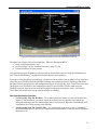
Using a Calibrated Video Display...........................................................................................................49
Paramount ME Initialization .............................................................................................................. 49
Homing.............................................................................................................................................................50
Why is Maintaining Accurate Time Important? ....................................................................................50
Setting the Computer’s Clock.........................................................................................................................51
Parking the Paramount ME ............................................................................................................................51
Parking from TheSky6 Professional Edition .........................................................................................51
Defining the Park Position ..............................................................................................................................51
Park Position Rules ................................................................................................................................52
Connecting the Electronics and Power ........................................................................................... 53
Through the Mount Cabling............................................................................................................................53
Cabling Supplied with the Paramount ME ............................................................................................53
Cable-Conduit..........................................................................................................................................54
Removing the RA and Dec Side Panels..........................................................................................................55
Remove the Declination Box Panel .......................................................................................................57
Rotate the Declination Axis....................................................................................................................57
Add Additional Cabling ...........................................................................................................................58
Assemble Mount .....................................................................................................................................58
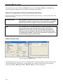
Interface to TheSky6 Professional Edition ...................................................................................... 58
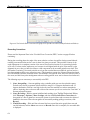
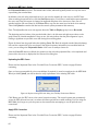
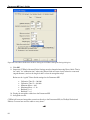
More Settings Dialog Box ...............................................................................................................................58
Mount Type.............................................................................................................................................59
Mount ID .................................................................................................................................................59
Maximum Speed .....................................................................................................................................59
Acceleration.............................................................................................................................................59
Non Sidereal Rate ...................................................................................................................................59
Guider Speed...........................................................................................................................................60
Track Rate ...............................................................................................................................................60
Home After Link .....................................................................................................................................60
Focus Pulse .............................................................................................................................................60
7
Paramount ME User’s Guide
Home Sensor Hour Angle and Sensor Declination .............................................................................. 60
Save to Flash........................................................................................................................................... 60
Copy to Clipboard ................................................................................................................................... 61
Periodic Error Correction (PEC) ................................................................................................................... 62
Recording the Periodic Error ......................................................................................................................... 62
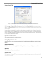
The Periodic Error Correction Tab ............................................................................................................... 63
Recording Corrections ........................................................................................................................... 64
Curve Fit: Smoothing the PEC Table ................................................................................................... 65
Polynomial/Sine Curve........................................................................................................................... 65
Uploading the PEC Curve...................................................................................................................... 66
Apply PEC Correction............................................................................................................................ 66
Recorded Table Group ........................................................................................................................... 67
Copy ........................................................................................................................................................ 67
Paste........................................................................................................................................................ 67
Zero Flash ............................................................................................................................................... 67
Status Tab........................................................................................................................................................ 68
Advanced Tab .................................................................................................................................................. 68
Homing/Limits Tab ......................................................................................................................................... 69
Right Ascension/Declination ................................................................................................................. 69
Homing Required Before Slew.............................................................................................................. 69
Allowed from Joystick ............................................................................................................................ 69
Home Axis .............................................................................................................................................. 69
Set Index Offset...................................................................................................................................... 69
Velocity High/Medium/Low................................................................................................................... 70
Direction S1, S2, Index .......................................................................................................................... 70
Minimum Limit, Maximum Limit, Set Limit Options .......................................................................... 70
Slew Between Limits ............................................................................................................................. 70
Count....................................................................................................................................................... 70
MKS 4000 Options Tab................................................................................................................................... 70
Slew Speed Adjustment (Temperature) Group.................................................................................... 71
If Degrees C is Below ............................................................................................................................ 71
Current (C) ............................................................................................................................................. 71
Current Percentage................................................................................................................................ 71
Apply (Percent of Maximum Slew Speed) ............................................................................................ 71
Global Setting Group.............................................................................................................................. 71
Unit Identifier (ID)/Reset ...................................................................................................................... 71
Enable Infrared ....................................................................................................................................... 71
Debug Output Group.............................................................................................................................. 72
General Purpose Input/Output .............................................................................................................. 72
Direction Output (1)............................................................................................................................... 72
Open Collector Output (1) ..................................................................................................................... 72
Direction Output (2)............................................................................................................................... 72
Open Collector Output (2) ..................................................................................................................... 72
System Reboot Group ............................................................................................................................ 72
Normal .................................................................................................................................................... 72
For Flash Update.................................................................................................................................... 72
For Motor Indexing ................................................................................................................................ 72
Communications Error Count ............................................................................................................... 72
The First Night.................................................................................................................................... 73
Quick Start....................................................................................................................................................... 73
8
Paramount ME User’s Guide
Synchronizing the Paramount ME..................................................................................................................74
What Does the Sync Command Do?...............................................................................................................74
The Local Celestial Meridian .................................................................................................................74
Best Synchronization Practices..............................................................................................................75
Performing a Telescope Synchronization ......................................................................................................76
Session to Session Pointing Repeatability ............................................................................................77
Making Sure Synchronization Is Correct .......................................................................................................77
Purple Region..........................................................................................................................................78
Red Region ..............................................................................................................................................79
Synchronization Checklist......................................................................................................................80
Starting Synchronization Over ...............................................................................................................80
Telescope Mapping Overview ........................................................................................................................80
To Prepare For a Mapping Session........................................................................................................81
To Map a Star ..........................................................................................................................................81
Using ProTrack™............................................................................................................................... 81
Minimum Requirements for ProTrack ..................................................................................................82
Getting Started with ProTrack...............................................................................................................82
Enabling ProTrack ..................................................................................................................................83
Activate ProTrack...................................................................................................................................84
Enable Tracking Adjustments................................................................................................................84
ProTrack Status Report ..................................................................................................................................84
Tracking Satellites ............................................................................................................................. 85
To Track a Satellite.................................................................................................................................85
Start/Stop Search ....................................................................................................................................87
DirectGuide™..................................................................................................................................... 87
To Enable DirectGuide...........................................................................................................................87
Cold Temperature Operation ............................................................................................................ 89
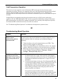
Troubleshooting Mount Operation................................................................................................... 89
Problem ...................................................................................................................................................89
Solution....................................................................................................................................................89
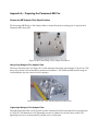
Appendix A – Preparing the Paramount ME Pier............................................................................ 91
Paramount ME Adapter Plate Specifications .................................................................................................91
Heavy-Duty Wedge to Pier Adaptor Plate ............................................................................................91
Lightweight Wedge to Pier Adaptor Plate.............................................................................................91
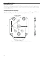
Primary Mounting Holes ........................................................................................................................92
Old Pattern (Paramount S Compatible) .................................................................................................92
Software Bisque Pier Specifications...............................................................................................................94
Pier Base Plate ................................................................................................................................................95
Pier Top Plate ..................................................................................................................................................96
Appendix B – Miscellaneous Paramount ME Specifications......................................................... 97
Paramount ME Dimensions............................................................................................................................97
Determining Pier Height ................................................................................................................................97
Guider Jack Wiring Specifications ..................................................................................................................97
Radio Shack® Cross Reference ..............................................................................................................98
Auxiliary Port 1 and 2 Fuse Replacement......................................................................................................98
9
Paramount ME User’s Guide
Purchasing 3A Slo-Blo Subminiature Fuses......................................................................................... 98
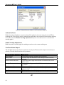
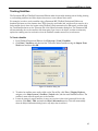
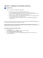
Appendix C – Updating the Control Software (Firmware).............................................................. 99
To determine your mount’s firmware version ..................................................................................... 99
Appendix D – Southern Hemisphere Setup and Use.................................................................... 103
Sensor Hour Angle (HA) and Sensor Declination (Declination) ................................................................ 104
Setting Telescope Limits..................................................................................................................... 104
Appendix E – USB Driver Installation and Use ............................................................................. 105
Minimum Requirements for USB Control................................................................................................... 105
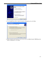
USB Driver Installation ................................................................................................................................ 105
Notes ..................................................................................................................................................... 105
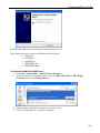
To Install the MKS 4000 USB Drivers ............................................................................................... 105
To Uninstall the MKS 4000 USB Drivers........................................................................................... 109
Using the MKS 4000 USB Port.................................................................................................................... 110
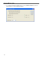
Determining the MKS 4000 USB COM Port Number ............................................................................... 110
Changing the MKS 4000 USB COM Port Number ..................................................................................... 111
Appendix F – FCC Compliance Statement .................................................................................... 113
Warning ......................................................................................................................................................... 113
Note ............................................................................................................................................................... 113
Index ................................................................................................................................................. 115
10
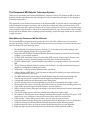
The Paramount ME Robotic Telescope System
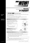
Thank you for purchasing the Paramount ME Robotic Telescope System. The Paramount ME is an ultraprecision German equatorial mount that is designed to deliver unmatched performance to the amateur or
professional astronomer.
This document covers the basic setup and use of the Paramount ME. It assumes that you are familiar with
many fundamental concepts in astronomy and are somewhat experienced using a telescope and or CCD
camera in conjunction with a personal computer. If a concept presented here is new to you, consider using
a search engine on the Internet to find out more information about the topic. Unfortunately, there’s simply
no way that all the different facets of setting up and controlling a robotic telescope mount can be covered in
a single document.
What Makes the Paramount ME So Different?
The Paramount ME is designed from the ground up to be a rock solid, reliable mount for instrument
payloads up to 68 kg (150 lbs.). The following features ensure that you’ll enjoy increased productivity and
superior results from your observing efforts.
•
•
•
•
•
•
•
•
•
•
•
•
•
•
•
•
•
•
•
•
Research-grade right ascension gears with seven (7) arcseconds or less peak-to-peak periodic
error, before applying periodic error correction (PEC).
Integration with TheSky6 Professional Edition Astronomy Software to control the mount locally,
remotely, or via scripted operation.
CCDSoft CCD Astronomy Software for controlling CCD cameras, adaptive optics, focusers, and
filter wheels, as well as performing image processing, data reduction and research.
CCDSoft’s DirectGuide™ feature eliminates the need for an autoguider cable on the Paramount
ME.
TPoint Telescope Pointing Analysis software with ProTrack™ provides unmatched pointing and
unguided, or autoguided, tracking performance.
Orchestrate™ scripting software automates data acquisition.
Software Bisque’s MKS 4000™ control system provides precise tracking, accurate periodic error
correction and smooth, fast slews.
The MKS 4000 control system supports a wide dynamic range for slewing and tracking rates.
Virtually any slew speed is available between stopped and several degrees per second.
Configurable acceleration and deceleration rates during slews.
Accurate homing sensors for rapid initialization and precision repeatability from night to night.
Homing allows the mount to be quickly reinitialized under any circumstance, including power loss.
Super-stable physical design that rapidly dampens external vibrations.
Built-in software slewing limits prevent damage to the mount and telescope by slowly decelerating
to limit regions.
Clutch-free design ensures consistent pointing and tracking from night to night.
50 conductors of through the mount cabling to minimize the nightmare of having CCD power, CCD
signal, focus, video, dew heater, and other accessory cables routed to the telescope.
Cable Conduit™ allows adding custom cables, wires or tubes through the mount.
Integrated equatorial wedge design that accommodates latitude adjustment from 15 to 58 degrees.
Integrated rotating base allows calibrated azimuth adjustment without affecting altitude.
Integrated altitude scale to provide an accurate altitude starting point for polar alignment.
Eight-inch right ascension bearing and six-inch declination provide maximum stability.
Paramount ME User’s Guide
•
Overall structural design makes the Paramount ME extremely rigid, even with very heavy
payloads.
Optional Accessories
•
•
•
•
•
•
•
•
•
•
•
•
TheSky Pocket Edition
TheSky Pocket Edition with Pocket TPoint
PrecisionPEC™ can be used to accurately determine the Paramount ME’s periodic error (under
virtually any seeing conditions) to generate an optimal periodic error correction curve for your
mount.
AutomaDome dome control software
Integrated precision bubble level
Counterweight shaft extension bar for balancing ultra-heavy payloads
Latitude Adjustment Wedge for use below 15 degrees and above 58 degrees latitude
Pier to Wedge Adaptor Plate for mounting the Paramount ME to an existing pier (heavy duty and
lightweight models)
Electronic panel covers/Balance knob covers (future)
Star-sighter (future)
Declination hub extender (future)
Software Bisque Paramount ME permanent piers
Unpacking the Paramount ME
We recommend you become familiar with the components of the Paramount ME before attempting to
assemble and use the instrument. Although we have taken many steps to ensure ease-of-use, there are
several critical steps that must be followed to achieve optimal performance.
Software Bisque has made every effort to ensure that your new mount arrives just the way it left our
facilities: fully operational and ready to use. We want your first experience to be as enjoyable as the hours
you’ll spend using it under the night sky. Please inspect all boxes for damage of any kind. If you notice
anything peculiar, make detailed notes before opening the packages (we recommend photographing or video
recording the unopened packages if there is any apparent damage).
After very carefully reading this section, remove all components from the packing boxes and check to make
sure they are in good order. Also compare the contents with the following packing list.
Please note that the Paramount ME comes fully assembled. In general, you should not have to dissemble
any component of the Paramount ME mount before using it. If you think you need to disassemble any
component of the mount, for any reason, please contact Software Bisque before doing so.
12
Paramount ME User’s Guide
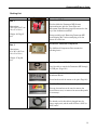
Packing List
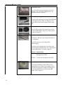
Item
Box 1
Dimensions:
76.2 x 68.6 x 45.7 cm
(30 x 27 x 18 in.)
Weight: 39.5 kg (87
lbs.)
Box 2
Dimensions:
61 x 30.5 x 30.5 cm
(24 x 12 x 12 in.)
Photograph
Description
Paramount ME Mount
This box holds the Paramount ME German
equatorial mount with the Versa-Plate and
Instrument Panel Housing (page 26) mounted to the
top of the declination assembly.
Please carefully read “Removing Paramount ME
from Shipping Box” before attempting to lift the
mount out of the box.
Paramount Additional Components
The Additional Components Box contains the
following items…
Weight: 27 kg (60
lbs.)
One 4.7 m (15-foot) USB Cable
Use this cable to control the Paramount ME through
its USB port. (Page 110.)
Four 3/8-inch, 24 thread-per-inch Base Plate
Attachment Knobs
These knobs attach the mount to the pier. (Page 30.)
One Allen Wrench Set
This set of wrenches can be used to remove the
Versa-Plate covers, or remove the mount side panels
(if necessary).
One Power Supply Cable
The female end of this cable is plugged into the
power supply unit, and the male end into a 120V (or
220V) outlet.
13
Paramount ME User’s Guide
Replacement Fuses
Two 3A Slo-Blo fuses for the adaptor panel. See
“Auxiliary Port 1 and 2 Fuse Replacement” for
replacement details. (Page 98.)
One 48V Power Supply Unit
Plug the small, round tip into the port labeled Power
on the Adaptor Panel. (Page 19.) Plug the power
supply cable into the power supply’s three-prong
port.
One Joystick
Insert the RJ11 plug into the joystick port on the
Paramount ME Adaptor Panel. See “The Joystick”
for details. (Page 35.)
One Counterweight Shaft
Dimensions: 460 mm (18 in.) long and 38 mm (1.5
in.) in diameter.
This shaft holds up to six (6) 9 kg (20 lb.)
counterweights.
Attach the counterweight shaft to the base of the
counterweight attachment block. See “Attaching the
Counterweight Shaft” for details. (Page 25.)
Thread
Male
Nominal Size
1 1/8-inch x 12 threads per inch (TPI),
60 degree form, UNF
Female
1/2-inch x 24 threads per inch (TPI)
One 3 m (10-foot) RS232 Serial Cable
The Paramount ME uses either USB or serial
communication for software-based mount control.
This cable runs from the computer’s RS232 port to
the port labeled RS232 on the Paramount ME
Adaptor Panel. (Page 19.)
14
Paramount ME User’s Guide
One Counterweight Safety Knob
Screw this knob into the end of the Counterweight
Shaft after adding counterweights. This knob
prevents the counterweight from sliding off the shaft.
See “Attaching the Counterweight Shaft” for details.
(Page 25.)
Counterweights
Two 9 kg (20 lb.) counterweights. Note that two
counterweights are supplied with the “standard”
Paramount ME. Contact Software Bisque if you need
to order additional counterweights.
Additional counterweights are shipped separately, in
a 30.5 x 30.5 x 30.5 cm (12 x 12 x 12 in.) box that can
hold up to three total counterweights. The weight of
this box is either 9 kg (20 lbs.) for one
counterweight, 18 kg (40 lbs.) for two additional
counterweights, or 27 kg (40 or 60 lbs.) for three
additional counterweights.
Attach the counterweights to the counterweight
shaft. See “Adding Counterweights” for details.
(Page 37.)
Optional
Component
Counterweight Extension Shaft Bar
This is an optional accessory and is not included with
the Paramount ME unless ordered separately. The
Counterweight Shaft Extension Bar screws into the
end of the Standard Counterweight Shaft for
additional counterweight capacity.
Dimensions: 178 mm (7 in.) long and 38 mm (1.5 in.)
in diameter.
The combined length of the standard counterweight
shaft plus the counterweight extension shaft (178
mm or 24-in.) holds up to eight (8) 9 kg (20 lb.)
counterweights.
This product can be purchased from the Software
Bisque Store at bisque.com.
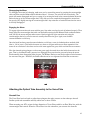
Box 3 (inside Box
2)
Dimensions: 23 x 30
x 8 cm (9 x 12 x 3 in.)
Paramount ME Software Suite
This box contains:
• One Paramount ME User’s Guide
• One TheSky6 Professional Edition on CD-ROM
15
Paramount ME User’s Guide
Weight: 1 kg (2 lbs.)
•
•
•
and DVD.
One CCDSoft version 5 CD-ROM.
One TPoint version 1 User’s Manual.
One Paramount ME System CD-ROM that
includes installation software for TheSky6
update, USB driver installation, CCDSoft version
5, TPoint Telescope Pointing Analysis Software,
Orchestrate, IAClient and IAServer software and
documentation in Portable Document Format
(PDF).
Note:
Location of TheSky6 Professional
Edition serial number.
•
•
•
TheSky6 Professional Edition serial number is
located on the inside flap of TheSky6
Professional Edition box.
The CCDSoft serial number is affixed to the
CCDSoft CD-ROM case.
The TPoint serial number is affixed to the title
page of the TPoint manual.
Location of the CCDSoft version
5 serial number.
Location of the TPoint version 1
serial number.
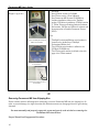
Removing Paramount ME from Shipping Box
Please carefully read the following before attempting to remove Paramount ME from the shipping box. In
order to prevent damage, the right ascension and declination worms are disengaged from the gears during
shipment.
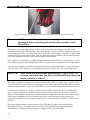
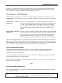
You must manually and properly engage the worm and gear in each axis before removing the
Paramount ME from the box!
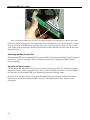
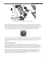
Proper Worm/Gear Engagement Procedure
16
Paramount ME User’s Guide
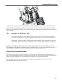
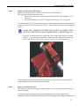
Engage the right ascension axis worm and gear by turning the right ascension balance knob
counterclockwise with one hand while gently wiggling the bottom of the declination axis with the other
hand (see Figure 1). Engage the declination axis worm and gear by turning the declination balance knob
counterclockwise with one hand while gently wiggling the end of the Versa-Plate with the other hand (see
Figure 1.).
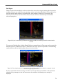
This procedure ensures proper that the worm and gear are properly engaged. The mount can now be safely
removed from the shipping box.
Figure 1: The black arrow points to the right ascension balance knob; the black circle indicates where to grasp and
wiggle the right ascension axis during engagement. The white arrow points to the declination balance knob; the white
circle indicates where to grasp and wiggle the declination axis during engagement.
17
Paramount ME User’s Guide
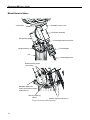
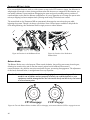
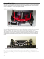
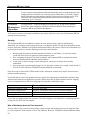
Mount Nomenclature
Declination motor cover
Versa-Plate
Telescope
plate
Declination assembly
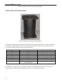
RA assembly
Counterweight attachment block
Counterweights
Wedge assembly
Pier
Counterweight shaft
Altitude retaining knobs
(2 each side)
Baseplate attachment
knobs (4) with Micro-levelers
underneath (4)
Altitude positioning
device
Azimuth adjustment knobs (2)
Figure 2: Paramount ME components.
18
Paramount ME User’s Guide
RA housing
Cable Conduit
(through RA shaft)
Adapter Panel
Figure 3: Paramount ME components (rear view).
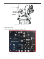
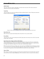
Adaptor Panel Basics
The table below describes each component of the Adaptor Panel.
Figure 4: Adaptor Panel (Paramount ME with the MKS4000 control system).
19
Paramount ME User’s Guide
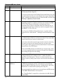
Number
Label
Description
1
Mount Power
Power switch to turn the mount on and off.
2
Focus
Input port for a pulse focuser. This port is identical to the Focus port on
the Instrument Panel. (Page 22.)
To control a pulse focuser from TheSky6 Professional Edition, first plug
the pulse focuser into this port (or the identical port on the Instrument
Panel), establish communication with the Paramount ME, and then click
Telescope | Options | Focus Control.
3
Guider
Input for the autoguider. Plug the autoguider cable into this port if your
autoguiding camera has a separate control box (for example, the SBIG
ST-V or ST-6). This port is identical to the Guider port on the
Instrument Panel. Plug the autoguider cable into the Guider port on
the Instrument Panel if your camera has a built-in autoguider (such as
the SBIG ST-7, ST-8, ST-9, etc.).
Note: If you use CCDSoft’s DirectGuide feature, no guider cable is
required. See the “DirectGuide™” heading for more information. (Page
87.)
4
Camera Power
This port is used to supply power from the base of the mount to the
port labeled Camera Power on the Instrument Panel. Early model SBIG
cameras used this type of plug for camera power.
If you own a camera that uses this type of power connector, then plug
the camera’s power into the Camera Power port, and use a short
camera power cable to plug into the Instrument Panel’s Camera Power
plug and then to the CCD Camera.
Newer model SBIG cameras use a different type of power plug, so this
port is not compatible with these cameras. See page 53 for information
about adding through-the-mount cabling.
5
Speaker Outlet
The Paramount ME’s speaker emits status sounds at startup, when
homing and during error conditions. See for “Audible Feedback” on
page 33 for more information. There is no volume control for the
speaker; however, placing a piece of tape over this hole will muffle the
sound.
6
Access to Fuses and
USB Port
This panel provides access to the USB port and fuses. See “Appendix E
– USB Driver Installation and Use” for details about controlling the
Paramount ME via USB. (Page 105.) See “Auxiliary Port 1 and 2 Fuse
Replacement” for details about replacing fuses (Page 98.)
This panel originally provided access to internal fuses and DIP switches
for the MKS 3200 and earlier control systems.
See “Visual Feedback” on page 32 for a description of the RA, Dec and
System LEDs.
20
Paramount ME User’s Guide
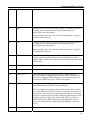
7
Aux 2
Auxiliary port two. This is one of two “generic” ports that can be used
to supply power to the Instrument Panel’s auxiliary ports for
accessories such as dew heaters.
Please carefully read “Aux 1 and Aux 2 Port Specification” on page 23
for details about this port.
8
Aux 1
Auxiliary port one. This is one of two “generic” ports that can be used
to supply power to the Instrument Panel’s auxiliary ports for
accessories such as dew heaters.
Please carefully read “Aux 1 and Aux 2 Port Specification” on page 23
for details about this port.
9
Parallel (25-line)
25-pin parallel port. If your camera has a parallel port interface, then
plug the camera’s parallel cable into this port, and then use a short
parallel cable to connect the parallel port on the Instrument Panel to the
camera head.
10
48-Volt Power In
Plug the 48-Volt power supply into this port (page 13).
11
Joystick
Plug the Joystick’s RJ11 (phone-type connector) into this port.
12
Serial To PC
This is the RS232 serial port that is used to communicate with a
personal computer or Windows Mobile device using a standard serial
port. Use the supplied RS232 cable (page 13) to connect this port to a
standard male DB9 serial port or USB to serial adaptor.
13
Aux I/O Port
Do not use this port. This port will be used by future firmware versions
of the MKS 4000 and TheSky6 Professional Edition.
This port contains four general-purpose, high-powered, driver outputs
that can be used to drive a DC servomotor or a stepper focus motor, or
other device. There are also two general-purpose pins that can be used
as inputs or outputs. We are currently looking at possible uses for these
functions such as an “abort slew” button, limit switch, or other use.
Earlier models of the MKS control system provided three “generic”
lines of through the mount cabling through this DB9 port (on pins 2, 3
and 5).
14
Aux Serial 1 (9-line)
The port provides nine “generic” lines of through-the-mount cabling.
21
Paramount ME User’s Guide
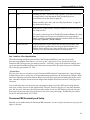
Instrument Panel Basics
Figure 5: Instrument Panel.
The table below describes each port on the Instrument Panel.
Number
Label
Description
1
Camera Power
This port is used to provide power from the Instrument Panel to the
camera head. Note: power to this port is supplied by plugging an SBIG
camera power cable into the Camera Power port on the Adaptor Panel.
(Page 19.)
2
Guider
Input for the autoguider. Plug the autoguider cable into this port if your
autoguiding camera has built-in autoguider (such as the SBIG ST-7, ST8, ST-9, etc.).
Use the port labeled Guider on the Adaptor Panel if your autoguider has
a separate control box (such as the SBIG ST-V or ST-6).
This port is identical to the Guider port on the Adaptor Panel. (Page
19.)
Note: If you use CCDSoft’s DirectGuide feature, no guider cable is
required. See the “DirectGuide™” heading for more information. (Page
87.)
3
Aux I/O Port
Do not use this port. This port will be used in future firmware versions
of the control system.
Earlier models of the MKS control system provided three “generic”
lines of through the mount cabling through this DB9 port (on pins 2, 3
and 5).
4
Aux Serial 1 (9-line)
The port provides nine “generic” lines of through-the-mount cabling.
5
Aux 2
Auxiliary port two. This is one of two “generic” ports that can be used
to supply power to the Instrument Panel’s auxiliary ports for
accessories such as dew heaters (page 52).
Please carefully read “Aux 1 and Aux 2 Port Specification” on page 23
22
Paramount ME User’s Guide
for details about this port.
6
Aux 1
Auxiliary port one. This is one of two “generic” ports that can be used
to supply power to the Instrument Panel’s auxiliary ports for
accessories such as dew heaters (page 52).
Please carefully read “Aux 1 and Aux 2 Port Specification” on page 23
for details about this port.
7
Focus
Input port for a pulse focuser. This port is identical to the Focus port on
the Adaptor Panel.
To control a pulse focuser from TheSky6 Professional Edition, first plug
the pulse focuser into this port (or the identical port on the Adaptor
Panel), establish communication with the Paramount ME, and then click
Telescope | Options | Focus Control.
8
Parallel (25-line)
25-pin parallel port. If your camera has a parallel port interface, then
plug the camera’s parallel cable into the port labeled Parallel on the
Adaptor Panel, and then use a short parallel cable to connect the
Parallel port on the Instrument Panel to the camera head.
Aux 1 and Aux 2 Port Specification
The manufacturing specification for the size of the Paramount ME Aux 1 and Aux 2 ports on the
Instrument and Adaptor Panel calls for a 2.1 mm “power” plug (this is a bit of a misnomer since the
Paramount ME’s Aux ports are not actually powered). “Lock ring” plugs that fit inside the auxiliary ports
can be purchased from Mouser Electronics (http://www.mouser.com), the name of the part is a Kobiconn
DC power plug, part number 171-7391. *
*Critical Note
The size of the Aux port connectors on your Paramount ME could be 2.5 mm instead of 2.1 mm. Although
Software Bisque tries to ensure the 2.1 mm manufacturing specification, the Instrument and Adaptor Panel
boards are manufactured outside Software Bisque by a third-party electronics manufacturing house, and to
date, a handful of Adaptor Panels have been shipped with Adaptor Panels that use the 2.5 mm plug for the
Aux ports.
You can tell which size your mount uses by comparing the inner post of the 48V Power In plug with the
inner post of either Aux port on the Adaptor Panel. The 48-V Power In plug has a 2.5 mm inner diameter
post; the Aux ports’ inner post should be noticeably smaller. If both the 48V Power In plug and Aux ports’
inner posts are the same size, then you’ll need to use the 2.5 mm power plugs. The Mouser part number
for the 2.5 mm Kobiconn DC is 171-7395.
Paramount ME Assembly and Setup
Now that you’re familiar with each Paramount ME component, it’s time to place the mount on your pier and
align it to the pole.
23
Paramount ME User’s Guide
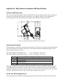
Approximate Altitude Adjustment
The mount’s altitude is set to the lowest position (15 degrees) for shipping. Before adding equipment or
counterweights, use the altitude-positioning device to set the altitude to roughly match the latitude of your
observing site.
Tip
Before Making Any Altitude Adjustments
The Paramount ME allows you to add your own through-the-mount cabling (page 53). Part of
this process requires the removal of five small, “non-structural” screws on the base of the RA
side panel. Some of these small screws are normally hidden behind the altitude wedge and can
only be removed when the mount’s altitude adjustment is at the highest position. (The latitude
of your observing site ultimately determines whether three or four screws are hidden behind
the wedge.)
Software Bisque recommends that you adjust the altitude to its highest setting and then remove
these “hidden” screws before performing a polar alignment. This ensures that the RA side panel
can be removed, (which is required for through-the-mount cabling), after polar alignment is
complete.
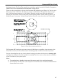
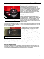
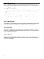
Altitude Divisions
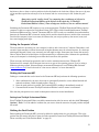
An altitude scale is machined into the wedge assembly. The scale
ranges from 15 degrees at the lowest position up to 58 degrees at
the highest. A Latitude Adjustment Wedge (sold separately) is
required for latitudes outside 15-58 degrees. Contact Software
Bisque to order this accessory. (See Figure 27.)
This scale allows you to set the mount’s altitude to a fraction of a
degree by aligning the base of the right ascension housing (the
gray arrow in the photograph) to the center of a “tic mark” (the
white arrow in the photograph). The altitude scale is extremely
accurate when the mount is level, but provides limited accuracy
when not.
Figure 6: Wedge assembly altitude
scale.
There are three different length tic marks on the altitude scale.
The longest tic marks represent 10-degree increments, the
medium marks represent 5-degree increments and the short
marks occur at one degree increments. The lowest setting is 15
degrees altitude, so that first long tic mark represents 20 degrees.
In the middle of the latitude range (approximately 36 degrees), one full turn of the altitude positioningdevice equals one degree, with slightly different amounts at the extremes. Each tic (or high spot) on the
altitude-positioning device knob is equal to two arcminutes (see Figure 26 for the definition of a tic on this
knob).
24
Paramount ME User’s Guide
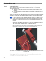
Figure 7: The arrow above shows the rotation direction for lowering altitude using the altitude-positioning device.
Loosen the four altitude retaining knobs (two on each side of the mount) about two complete turns. This
allows the right ascension housing to move freely within the wedge assembly using the altitude-positioning
device (Figure 7).
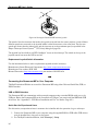
Tip
Remember the “Right Hand” Rule!
The Paramount ME uses “right-handed” threads. If you need to make an altitude adjustment,
and forget which direction to rotate the altitude-positioning device, just use the right hand rule.
For example, suppose you need to increase the mount’s altitude. Point the thumb on your right
hand upward. Rotate the altitude-positioning device in the direction your fingers curl. Simple!
Initially, consider adjusting the altitude slightly higher than your latitude so that any adjustment during
polar alignment is downward. If the altitude must be adjusted higher, you can lift the declination housing, or
counterweight shaft (page 25) to make rotating the altitude-positioning device easier.
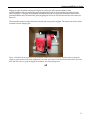
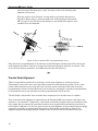
Attaching the Counterweight Shaft
The counterweight shaft should be threaded into the bottom of the declination housing (Figure 8) until
tight. The counterweight safety knob screws into the opposite end of the shaft. To be safe, this knob should
always be in place whenever any counterweights are mounted on the counterweight shaft.
Insert a large hex wrench or screwdriver into the small, unthreaded hole near the “bottom” of the
counterweight shaft to help rotate the shaft.
25
Paramount ME User’s Guide
Figure 8: Attaching the counterweight shaft.
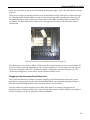
Positioning the Versa-Plate
The Versa-Plate (see Figure 9) measures 7.9 inches by 20.0 inches by 0.9 inches, and is designed to
securely hold a wide variety of optical tube assemblies, OTA mounting rings, as well as optics that employ
the LosmandyTM dovetail system. It can be mounted in three different positions (forward, middle and back)
to accommodate different weight distributions of different equipment.
The Paramount ME is assembled and shipped with the Versa-Plate mounted in the forward-most position.
This position should work a wide-variety of equipment and optical tube assembly combinations so that you
should not need to change it. However, if you need to adjust the Versa-Plate’s position to achieve balance
in declination for your optical system and equipment, the following documentation describes how to do so,
as well as how to attach the Instrument Panel to the Versa-Plate.
Figure 9: Photograph of the Versa-Plate. The arrows indicate the position of the three grooved circles; each circle
represents a different mounting position.
The pattern of holes used to attach the Versa-Plate to the top of the declination housing is repeated in
three places on the Versa-Plate. This allows the plate to be centered, or mounted approximately one inch
in either direction from center.
The positions of the three mounting locations are represented on the top of the Versa-Plate as eight-inch
grooved circles (see Figure 9). Each circle corresponds to the location of the declination housing when the
Versa-Plate is mounted at that position. Attaching the Versa-Plate to the middle circle centers it on the
26
Paramount ME User’s Guide
declination housing. The Versa-Plate can also be moved about one inch forward (for Schmidt–Cassegrain or
similar OTAs) or one-inch backward (for Newtonians or longer OTAs).
There are twelve tapped holes in the top of the Paramount ME declination gear (Figure 10). The four inner
holes accept 1-inch, ¼-20 thread, flat socket cap screws (± 0.001 inches). The eight outer holes accept 1inch ¼-20 socket head cap screws (± 0.001 inches). Normally, the eight outer holes are sufficient for
mounting the Versa-Plate. The four inner holes permit attaching smaller (custom-made) top plates to the
declination gear, if necessary. Software Bisque attaches all twelve screws when the mount is assembled.
Figure 10: Versa-Plate mounting specifications.
The Paramount ME’s declination axis cannot rotate a full 360 degrees, regardless of the orientation of the
Versa-Plate; therefore, the Versa-Plate must be mounted properly to ensure normal mount operation.
An arrow is machined into the top of the declination housing that indicates the direction of incoming light
(see Figure 11 and Figure 12) for the optical tube assembly. Use this to arrow to determine the orientation
of the Versa-Plate for your optical system.
Notes:
• The machined arrow should not point toward the entrance pupil of the optical tube assembly.
• The declination assembly (that is, the component on which the arrow is machined) should never be
disassembled for any reason.
27
Paramount ME User’s Guide
If you must remove the Versa-Plate for any
reason, please take note that an arrow is machined
into the declination hub as a guide to ensure that
the orientation of the Versa-Plate is correct.
Specifically, attach the Versa-Plate so that this
arrow points in the same direction as the light that
comes into the optical tube assembly (see Figure
12).
Figure 11: Photograph of the top of the declination housing (note machined arrow).
Figure 12: Typical (left) and wide (right) Versa-Plate mounting configurations. The black arrows indicate the
direction of incoming light. Note that the machined arrow on the declination hub points in the same direction as the
incoming light.
The Paramount ME is shipped with the Versa-Plate mounted in the “typical configuration” as shown in the
left drawing in Figure 12. Note that the arrow on the declination hub points in the direction of incoming
light to the telescope and toward the Instrument Panel (mounted to the bottom of the Versa-Plate). This
orientation ensures maximum rotation of the declination axis without hitting the hard stop at -90 degrees
declination.
The Versa-Plate can also be mounted at 90 degrees from the typical orientation, offering a wide mounting
surface that can accommodate multiple optical tube assemblies. Note the machined arrow on the
declination hub still points in the direction of the incoming light, but not toward the Instrument Panel as in
the typical configuration.
A third configuration (not pictured) places the Instrument Panel near the entrance pupil of the telescope. In
this orientation, cabling to the CCD camera follows the shortest route for Newtonian telescopes. The
Versa-Plate is rotated 180 degrees from the typical configuration pictured above.
Note that the machined arrow must always point in the direction of incoming light, regardless of the
configuration.
28
Paramount ME User’s Guide
Attach the Versa-Plate to the top of the declination housing using eight 1-inch ¼-20 socket head cap screws
(page 13).
There are two cables that protrude from the top of the declination housing. Both must be directed through
the Versa-Plate cable channel. Make sure that you have just enough cable protruding out of the top of the
declination housing to reach the Instrument Panel. Extra cable makes assembling the Instrument Panel
box difficult. Too little slack and the cables cannot be plugged into the slots on the Instrument Panel’s
control board.
Figure 13: Channel Covers (unanodized for illustration purposes)
The channel covers are shown in Figure 13. There are three channel separate covers to accommodate the
three Versa-Plate mounting configurations. The “typical configuration” uses the large cover and only one
of the two rectangular covers. The “Schmidt-Cassegrain” configuration uses only the large cover. The
“Newtonian configuration,” shown above, requires all three channel covers.
Plugging In the Instrument Panel Electronics
This section describes the procedure for properly plugging in the Instrument Panel electronics, and is
included for reference purposes only, since the Paramount ME is now assembled and shipped with the
Instrument Panel Housing and electronics already mounted to the Versa-Plate.
After the cables are passed through the Versa-Plate cable channel, they must be plugged into the
appropriate slots on the Instrument Panel’s control board. Inspect the two cables to identify the alignment
notches (see Figure 14). Do not plug these cables in backwards!
29
Paramount ME User’s Guide
Figure 14: Important! Make sure the notches are aligned properly to avoid plugging the cables in backwards.
Once these cables are plugged in to the Instrument Panel control board, use a 3/32 hex wrench to connect
the front and back of the Instrument Panel box. Next, use a 5/32 hex wrench to attach the four 1 ½-inch
10/32 socket head cap screws in the back of the Instrument Panel assembly into the bottom of the VersaPlate (Figure 13).
Attaching the Mount to the Pier
The Paramount ME uses integrated Micro-Levelers and Base Plate Attachment Knobs to level and secure
the mount to the pier or base plate. Please carefully read the section “Adjusting the Micro-Levelers”
before continuing.
Adjusting the Micro-Levelers
The Paramount ME’s Micro-Levelers are used to fine-tune the mount’s level. The maximum amount of
adjustment for each leveler is approximately 3 mm or 1/8-inch. The Micro-Levelers are also used ensure
the base plate of the Paramount ME is not distorted by an uneven mounting surface.
Important note: the Micro-Levelers must protrude slightly below the surface of the Base Plate before
tightening the Base Plate Attachment Knobs. See the “Critical Micro-Lever Note” below for more
information.
30
Paramount ME User’s Guide
The best approach for leveling the mount is to
simultaneously rotate two Micro-Levelers so that the
mount is tilted either East/West or North/South. The
accuracy of the leveling required depends on the long-term
use of the mount. If the mount is attached to a permanent
pier, without the intent of portable use, leveling is less
important. When used in a portable sense, a level mount
helps speed the polar alignment process.
Critical Micro-Lever Note
Figure 15: Micro-Leveler (white arrow) and
Base Plate Attachment Knob (gray arrow).
The Micro-Levelers and Base Plate Attachment Knobs
serve different purposes. The Micro-Levelers stabilize and
level the Base Plate. The Base Plate Attachment Knobs
secure the Base Plate to the pier. Both components have
unique thread patterns, and the two will bind together when
improperly adjusted.
The weight of the mount must be resting on all four Micro-Levelers, and not on the Base Plate. That is, the
Base Plate should sit at least one millimeter (or so) above the mounting surface (such as the top of the pier
or, or the pier adaptor plate).
To make sure this occurs, before tightening the Base
Plate Attachment knobs, rotate each Micro-Leveler
clockwise until it makes contact with the mounting
surface. Then tighten it about 1/16 of a turn (or so)
more. Additional adjustment may be required to
accommodate uneven mounting surfaces. You might
want also want to gently lift the mount when tightening
the Micro-Levelers.
If all four Micro-Levelers are not in contact with the
mounting
surface, when you attempt to loosen a Base
Figure 16: Adjusting Micro-Levelers.
Plate Attachment Knob, both will turn together and bind.
They cannot be turned in unison because the threads on the Micro-Leveler are larger than the threads on
the Base Plate Attachment Knob. If the two become bound, do not try to force them apart! Instead
tighten (yes, tighten) both knobs a small amount until they are no longer bound. At this point, rotate the
Micro-Leveler clockwise until it is in full contact with the mounting surface.
Base Plate Attachment Knobs
The Paramount ME attaches to the pier using four Base Plate attachment knobs near the corners of the
Wedge Base Plate (Figure 17). Typically, tightening them by hand is sufficient to fix the mount into place.
Over tightening these knobs is unnecessary and can lead to binding as described above.
31
Paramount ME User’s Guide
Figure 17: Location of Base Plate Attachment Knobs.
First Time Operation
After you have assembled the Instrument Panel and attached the Versa-Plate, verify that the electronic and
mechanical components operate by switching the Mount Power button to the on position. (See “Connecting
the Electronics and Power” on page 52 for details about connecting the 48-Volt power supply to the
Adaptor Panel).
Figure 31: Paramount ME Adaptor Panel.
Note that the Paramount ME will not respond to joystick or TheSky6 slew commands and will not begin
tracking until the control system is homed. See “What Is Homing?” on page 34 for details.
Visual Feedback
When the mount is turned on, three LEDs provide visual feedback on the status of the control system.
Note: The LEDs are only visible when the Adaptor Panel’s Access Panel is removed (page 110). An orange
LED constantly pulses to indicate that the electronics are functioning normally. Two blue LEDs flash while
32
Paramount ME User’s Guide
the control system is being initialized, and remain steady after successful initialization. If one or both LEDs
are not lit after the mount is powered on, it means that there was a problem initializing the control system.
The mount will also emit a continuous beeping sound if this occurs. Turn the mount off and check to make
sure that the joystick is in the center position, and that there are no obstructions that might impede
mount’s ability to slew before proceeding.
Audible Feedback
While the Paramount ME is turned on, please listen! The control system emits different sounds to indicate
the status of initialization operations, error conditions, and will also “hum” during normal operation.
Sounds Emitted During Mount Initialization and Operation
Each time the mount is turned on the control system performs a servomotor initialization procedure in
each axis. Two successive beeps (up to about ten seconds or so apart) indicate success.
If the button on the joystick handle is pressed and held down when the mount is turned on, or the joystick
is moved from the center position before the servomotor initialization is complete, then the initialization
procedure is aborted. When this happens, the mount emits a single beep. When initialization is interrupted,
the control system will not attempt to drive the motors. Before attempting to slew or home the mount,
make sure the joystick is in the center position, power the mount off then on, and then wait for the two
beeps that indicate the mount is ready for normal operation.
The table below describes the different sounds that the mount can emit, when the sound occurs, and a
description of what the sound indicates.
Sound
Two beeps from
about five to ten
seconds apart.
Occurs
Shortly after mount is
turned on.
Description
Indicates that the control system has located the DC
servomotors “index” position in right ascension and
declination. This means that the control system has
initialized the servomotors and is ready for normal
operation.
Single beep.
When the servomotor
initialization is interrupted,
shortly after mount is
powered on. One or more
blue LEDs is not lit.
Mount servomotor initialization can be interrupted by the
following actions.
• Pressing and holding the joystick button down and
turning on the mount.
• Moving the joystick from its center position
before the servomotors are initialized.
• Attempting to slew or home the mount from
TheSky6 Professional Edition before servomotor
initialization. For normal initialization, simply turn
on the mount and wait for the two successive
beeps, without attempting to control the mount
via joystick or TheSky6 Professional Edition.
• The Balance Knobs on either axis are too tight,
and the servomotors cannot turn (page 40).
Three successive
beeps.
Shortly after the mount has
slewed to the home
Indicates that mount has successfully located the home
position for one axis. See “What Is Homing?” on page 34
33
Paramount ME User’s Guide
position in each axis.
for more information about homing.
Variable-pitched
hum.
Always.
When the Paramount ME is turned on and initialized, the
servomotors emit an audible, variable-pitched sound. This
sound is the result of the control system checking and
adjusting the position of the servomotors about 3,000 Hz,
and is normal. This sound serves as the audible
“heartbeat” of the mount, and means that the electronics
are powered and functioning normally.
Continuous,
successive, highpitched beeps.
May occur when attempting This sound indicates a control system error condition,
to slew the mount after
which prevents the servomotors from turning. Typical
adjusting one or both of the causes include:
Balance Knobs.
• Worm/gear tension is excessive. Try adjusting the
Balance Knobs. (Page 40.)
• Ambient temperature is too low for the current
tracking and slew speed settings. (Page 85.)
• Payload is out of balance, causing the motors to
stall.
See “Troubleshooting Mount Operation” on page 89 for
additional troubleshooting tips.
Single “click” or
“tic” sound
During serial
communications.
The Paramount ME with the MKS 4000 control system
will emit a single "click" (or "tic") when serial
communications between the mount and TheSky6
Professional Edition are interrupted. Interruption can
occur, for example, when a camera is downloading an
image, or during other processor intensive operations.
Notes:
• The clicking noise is normal and expected
behavior.
• The clicking noise is not indicative of any
problems with the mount.
• There is currently no way to “disable” this audible
feedback.
What Is AutoHoming?
AutoHoming is an automated initialization process that slews both the right ascension and declination axes
to a mechanically fixed position called the home position. The control system must perform this step every
time the Paramount ME is turned to reestablish the mount’s absolute position to the nearest one-third
arcsecond.
Critical Note
34
The home position in the northern hemisphere is located at approximately hour
angle 2 and 0 degrees declination. The home position is a fixed, mechanical
orientation and cannot be changed; it is defined by the physical position of the gears
Paramount ME User’s Guide
relative to internal homing sensors. If the mount is not physically pointing to
approximately hour angle 2 and 0 degrees declination after the home position is
located, then either the Versa-Plate is mounted incorrectly (page 41), or the
mount’s right ascension axis is not aligned north-south. If the coordinates of the
telescope cross hair in TheSky6 show a different position after homing, then
TheSky6’s time or sync information is incorrect (page 77).
Critical Note
The Paramount ME will not slew or track until the mount
is successfully homed.
When the mount is homed, it slews to the home position and sets the control system’s “position registers”
to zero. When star synchronization is performed, the hour angle and declination of the home indexes are
stored in the internal flash of the Paramount ME’s control system. Subsequent sessions simply use the
local sidereal time, as computed by TheSky6 Professional Edition, to accurately determine the mount’s
equatorial coordinates. Make sure TheSky6’s time is accurate (see page 50).
Homing provides the following benefits.
•
•
•
•
Once a mount is aligned with the celestial pole and homed, extremely repeatable and accurate
pointing can be achieved using TheSky6 Professional Edition and the TPoint Telescope Pointing
Analysis software.
After homing, the mount “knows” its orientation and therefore cannot be slewed into the pier. The
right ascension limits are approximately 5 degrees past the meridian in each direction (east and
west) and in declination the limit is approximately –90 degrees declination.
The periodic error correction (PEC) function uses this information to calibrate the control system’s
internal PEC table with the orientation of the worm gear.
You can quickly recover from power outages or other communication malfunctions.
Homing the Mount Using the Joystick
To home the mount using the joystick, make sure the mount is powered, and the servomotors are
initialized (see page 33), then deliberately tap the button on top of the joystick handle twice. If you move
the joystick during the homing procedure, the mount stops slewing and homing is aborted. Left-right
motion causes the RA axis to stop slewing; forward or backward motion causes the declination axis to stop
slewing (see Figure 18).
Homing Troubleshooting
Remember, the home position is a mechanically fixed orientation near hour angle 2 and declination 0. If,
after homing the mount, TheSky6 Professional Edition reports that the mount is pointing elsewhere, then
the mount is not synchronized correctly. See “Synchronizing the Paramount ME” on page 74 for more
information about synchronizing the Paramount ME.
The Joystick
In addition to homing the mount, the joystick can be used to manually slew each axis.
35
Paramount ME User’s Guide
Figure 18: Slewing the Paramount ME with the joystick.
The speed of the slew increases the further the joystick is moved from the center position. A total of fifteen
different speeds are traversed as the joystick handle is tilted from center to the outer limit. The first two
speeds are slower than the sidereal rate, and they increase up to the maximum speed, as specified in the
Bisque Telescope Control System TM (TCS) Setup dialog box (page 58).
The joystick box has a built-in red LED “flashlight” for use at the telescope. The switch on the top of the
joystick control box turns this LED on and off.
Replacement Joystick Switch Information
Use the information below to order a replacement joystick switch if necessary.
Manufacturer: Omron Electronic Components (http://www.components.omron.com)
Manufacturer Part number: B3W-1050
Mouser Electronics (http://www.mouser.com) part number: 653-B3W-1050
Connecting the Paramount ME to Your Computer
TheSky6 Professional Edition can control the Paramount ME using either Universal Serial Bus (USB) or
RS232 interface.
USB or RS232 Interface
The Paramount ME can communicate with a personal computer using a standard RS232 serial port, or by
USB port. Before the Paramount ME can be controlled via USB port, you must install the MKS 4000 USB
driver first. See “Appendix E – USB Driver Installation and Use” for details. (Page 105.)
Quick Start for Experienced Users
For this section, an experienced user is someone who is familiar with the operation of a go to telescope.
1. Connect the Paramount ME to your computer using the supplied RS232 or USB cable (USB drivers
must be installed first), then turn on the mount.
2. For TheSky6 Professional Edition, click Telescope | Setup.
36
Paramount ME User’s Guide
3. On the Telescope or Control System Name list, select Paramount ME by Software Bisque
and then click Settings.
4. On the Settings dialog box, select the appropriate COM port from the list and then click OK.
5. Click Close.
6. Click Telescope | Link | Establish to establish communications with the Paramount ME.
See “Paramount ME Initialization” on page 49 for additional information.
Homing the Mount Using TheSky6 Professional Edition
Upon establishing a link with the Paramount ME, TheSky6 Professional Edition displays the dialog box in
Figure 19 when the mount has not been homed.
Figure 19: TheSky6 Professional Edition‘s Find Home dialog box.
Click Yes to home the mount. To home the mount at any time using TheSky6 Professional Edition, click
Telescope | Options | Find Home. See “Quick Start” on page 73 for more information about homing.
The mount can now be controlled from TheSky6 Professional Edition. For practice, click Telescope |
Motion Control and use the direction buttons to slew the mount so that the counterweight shaft is vertical
(when viewed from the rear of the mount).
Determining the Paramount ME’s Equatorial Coordinates
The Paramount ME does not employ conventional “setting circles.” Instead, use TheSky6 Professional
Edition to determine where the mount is pointing. From TheSky6 Professional Edition, click the Status
Bar command from the View menu, mark the Telescope Position option and then click OK. The equatorial
coordinates of the telescope are displayed in the Status Bar.
Adding Counterweights
Counterweights should be added to the counterweight shaft only if the counterweight shaft is vertical, or
the right ascension gear and worm are disengaged. See “Disengaging the Worm” on page 41 for more
information.
37
Paramount ME User’s Guide
Figure 20: Orientation of the counterweight shaft that exerts the minimum stress on the worm.
Note
Add the estimated amount of counterweight to balance your
equipment before attaching the optical tube assembly to the
Versa-Plate.
The amount of counterweight required to achieve balance depends on the weight of the optical tube
assembly and accessories. Estimate how much counterweight is required, and then add this amount to the
counterweight shaft. Err on the heavy side. That is, better the counterweights “outweigh” the optical tube
assembly by being too far down the shaft. This way, when fine-tuning the balance, the counterweights will
tend rotate downward, instead of your expensive optical tube assembly.
Once sufficient counterweights are added, the right ascension axis should be very “bottom heavy.” At this
point, adding the optical tube assembly should result in a system that is somewhat close to being balanced.
After the counterweights are added, firmly tighten each of the counterweight knobs to ensure they do not
slip. Also, make sure to install the counterweight safety knob on the bottom of the counterweight shaft.
Safety Tip
Each counterweight weighs approximately 9 kg (20 lbs). Use
extreme caution so that you do not accidentally drop them and
injure yourself, or others!
Depending on the size and weight of your optical tube assembly (OTA), you might want to solicit a friend
(or two) to help lift, orient and attach this component. The Losmandy dovetail mounting brackets provide a
stable mounting interface for most off-the-shelf OTAs. Be sure to sufficiently tighten all mounting screws.
To limit the stress placed on the right ascension gear teeth while attaching the OTA to the declination
plate, the right ascension axis should be rotated so that the counterweight shaft is vertical as shown in
Figure 20. Then estimate the amount of counterweight that is required and mount it to the counterweight
shaft. In this configuration, the out-of-balance system is in a static state and the gear teeth are not
supporting the entire load of the counterweights. Once the counterweights are in place, the OTA can be
attached.
Great care should be taken to center the mass of the OTA near the center of the declination axis.
Depending on the type of hardware used to attach the OTA, this adjustment can be made during
attachment or by moving mounting rings prior to lifting the OTA to the Versa-Plate.
38
Paramount ME User’s Guide
Figure 21: This figure shows a Paramount ME that is dangerously out of balance.
Caution! Never position the Paramount ME in the above orientation when
the worm gear is engaged!
The Paramount ME, as pictured in Figure 21, is in an unstable configuration and places
extreme torque on the right ascension gear teeth. The counterweight shaft should remain in
the vertical position while the Paramount ME is loaded with counterweights and the OTA
has not yet been attached. This minimizes the torque on the right ascension gear teeth and
ensures the mount is in a stable position at all times.
Balance the System
Attach your CCD camera and all other equipment (focuser, filter wheel, field rotator, dew heater, etc.) to
the optical tube assembly while balancing the mount. The telescope will operate best when properly
balanced. An unbalanced system can cause numerous problems, such as stalling or “gear chattering” during
slews. There is no clutching mechanism on the Paramount ME. To achieve balance, disengage the worm
from the gear in each axis, and then adjust the position of the counterweights on the counterweight shaft.
Caution!
Always use extreme care when balancing the telescope! Make note of the weight
distribution on the telescope before disengaging the worm block assembly from the
gear. Always firmly grasp the OTA or counterweight shaft before disengaging the
worm and gear so that you maintain control of the telescope.
The telescope could be damaged, or you could be seriously injured whenever the worm gear is disengaged
from the main gear on an unbalanced system.
The Paramount ME comes with two 9 kg (20 lb.) counterweights to balance the optical tube assembly. To
balance the right ascension axis, slide the counterweights up or down the counterweight shaft until the
system has no tendency to rotate in either direction.
39
Paramount ME User’s Guide
If you use multiple detectors, such as a video camera to map, and a CCD camera to image, the difference in
weight might be enough to cause slewing problems when the detectors are swapped. In this situation, you
can quickly rebalance a system without disengaging the worm and gear by marking various positions of
counterweights on the shaft for different configurations. It is very important not to change the system after
telescope mapping has been completed and a pointing model using TPoint has been created.
The worm blocks on the Paramount ME can permanently disengage the worm from the gear while
balancing the system. Though it is always a good idea to have a second person available to help hold the
OTA during balancing, this mechanism allows a single person to achieve balance.
Figure 22: Location of the RA Balance Knob.
Figure 23: Location of the Declination
Balance Knob.
Balance Knobs
The Balance Knobs serve a dual purpose. When turned clockwise, they pull the worm away from the gear,
allowing free rotation of the axis so that the mount’s payload can be balanced. When turned
counterclockwise, they hold the worm into mesh with the gear, preventing disengagement. The adjustment
of this knob, discussed below, is straightforward but very important.
Caution!
Always be extremely careful when disengaging the worm from the gear! If the
mount is out of balance and not properly secured, you could be injured, or your
equipment could be damaged when the axis rotates freely and the heavy end comes
to rest at lowest point.
CW=Disengage
CCW=Engage
Figure 24: Turn the Balance Knobs clockwise (CW) to disengage, and counterclockwise (CCW) to engage the worm.
40
Paramount ME User’s Guide
Disengaging the Worm
To disengage the worm for balancing, make sure you’ve secured the mount by grasping the counterweight
shaft, and then turn the Balance Knob clockwise about 1-1/2 turns. The axis can now rotate freely. The
worm will remain disengaged until you re-engage it by rotating the knob in the counterclockwise direction.
Before letting go of the counterweight shaft, verify that you have completely disengaged the worm from
the gear by very slightly moving the counterweight shaft. Any resistance to rotation means that the worm
is not fully disengaged.
Engaging the Worm
To engage right ascension axis worm with the gear, first make sure that the axis is balanced properly. Then
firmly grasp the counterweight shaft with one hand while turning the RA Balance Knob counterclockwise
until you feel the worm and gear make contact. Gently wiggle the right ascension axis using the
counterweight shaft to be sure the worm is actually seated into the gear. Again, turn the knob
counterclockwise to a full stop.
Once the knob has been rotated counterclockwise to a full stop, rotate it clockwise about one knob click
(that is, 1/10 of a turn). This holds the worm very close to the gear and does not allow separation if the
mount is out of balance. It also does not force the worm against the gear, which can bind the servomotors.
Note that internal spring plungers on the worm gears apply the actual force that holds the worm into the
gear. That is, the balance knobs’ purpose is to disengage the worm from the gear and to keep the worm
block assembly from disengaging from the gear. The Balance Knobs are not used to adjust tension between
the worm and the gear. However, the Balance Knobs can be over tightened and bind the servomotors.
Figure 25: RA Balance Knob
Attaching the Optical Tube Assembly to the Versa-Plate
Dovetail Use
The Versa-Plate has four knobs to adjust brass plungers that apply pressure on the telescope dovetail.
Smaller optical tube assemblies will only utilize two or three of these.
When mounting your OTA, orient the long dimension of Versa-Plate parallel to an East–West line, with the
counterweight shaft vertical. When the Versa-Plate is in this orientation, you can mate the dovetails
41
Paramount ME User’s Guide
without the risk of the OTA “falling out.” We recommend placing the Versa-Plate knobs “uphill” (that is,
with the telescope pointing to the west) so that when they are tightened, you are not trying to lift the OTA.
Attaching OTA Mounting Rings
The four separate mounting configurations provided on the Versa-Plate accommodate several popular OTA
mounting ring systems. The holes are drilled and counter-bored for ¼-20 SHCS (socket head cap screws).
Cable Channel
The underside of the Versa-Plate has a channel to make room for the “through the mount” cables.
Additional cables and accessories (such as video, USB, camera cooling hoses, etc.) can be run through the
mount. See “Through the Mount Cabling” on page 53 for more information.
Initial Polar Alignment
There are numerous methods for estimating the approximate altitude and azimuth settings before starting
the polar alignment procedure. Ideally, you will want to get each axis to within one or two arcminutes for
portable setups, or to better than an arcminute in each axis if you have a permanent installation.
Altitude Adjustment
The altitude-positioning device is used to adjust the altitude of the mount. The mount sits at altitude 15
degrees at the lowest setting and 58 degrees at the highest setting. One rotation of the altitude positioning
device moves the mount about one degree. Therefore, each “tics” on the altitude positioning handle is
equal to two arcminutes of movement.
Azimuth Adjustment
The Paramount ME uses an innovative design that allows you to adjust the mount’s azimuth without
changing its altitude. The base plate consists of an outer, fixed plate and an inner rotating plate on which
the mount sits. Adjustment in azimuth is achieved by turning the “azimuth adjustment knobs” at the front
of the mount (see Figure 26).
42
Paramount ME User’s Guide
Figure 26: Azimuth adjustment knobs and tensioning screws.
The two azimuth adjustment knobs work in opposition – one must be loosened before the other can be
tightened. The knob that is tightened rotates the wedge assembly; the knob that is loosened gives “room”
for the mount to rotate. Note that a fully loaded mount may make tightening the knobs by hand difficult. If
this is the case, insert a 5/32 Allen wrench into the center of the adjustment knob to assist rotation.
Provided the opposite knob is loose, the mount will rotate without having to exert excessive force.
Figure 27: Each high spot or “tic” on the azimuth adjustment knob represents two arcminutes azimuth adjustment.
The azimuth adjustment knobs are calibrated. One rotation results in 30 arcminutes of azimuth adjustment.
Therefore, each “knob-tic” (that is, each high point on the knob itself, see Figure 27) equals two
arcminutes.
Azimuth Tensioning Screws
The two azimuth tensioning screws can be adjusted by inserting a hex wrench into the front of the
Paramount ME base plate (the two straight arrows in Figure 26). These tensioning screws push pliable
Delrin plungers against the internal rotating wedge plate. This means that you can continue to tighten the
azimuth tensioning screws without ever feeling a hard stop, so be cautious not to over tighten them.
Adjustment to the azimuth can be performed without loosening the azimuth tensioning screws, but can
make turning the azimuth adjustment knobs difficult. Typically, the azimuth tensioning screws are
loosened by about one turn before making azimuth adjustments. Once you are satisfied with the polar
alignment in azimuth, retighten the azimuth tensioning screws.
43
Paramount ME User’s Guide
Note that each tic on the azimuth adjustment knob represents two arcminutes of rotation of the base plate
(Figure 27). These calibrated knobs are especially useful when making quantitative azimuth adjustments
that are recommended by TPoint’s polar alignment command.
Additional Azimuth Adjustment
Figure 28: The azimuth “nosepiece” can be repositioned for additional azimuth adjustment.
If you need additional azimuth adjustment, there are two additional sets of mounting holes for the azimuth
adjustment “nosepiece” that allow for about two degrees azimuth adjustment in either direction.
The “nosepiece” is the black anodized part that protrudes into the azimuth adjustment block (see Figure
28), by which the mount is rotated. Loosen the two azimuth adjustment knobs and remove the four hex
screws from the adjustment knob-mounting bracket. These screws are accessed from the bottom of the
mount.
Figure 29: Remove these four screws to access the azimuth nosepiece. (View from the bottom of the mount.)
Next, remove the four hex screws that hold the nosepiece in place. You'll see the additional sets of
mounting holes beneath this piece. Remount the nosepiece in the holes that give you the desired azimuth
adjustment.
44
Paramount ME User’s Guide
Paramount ME Quick Polar Alignment Method
The Paramount ME contains homing sensors that can be used to aid in the first step of polar alignment.
Each time the Paramount ME is homed, it returns to the exact same position (that is, to the nearest
encoder tic, or a fraction of an arcsecond). This position is very near hour angle 2 and declination 0. This
represents a point in the sky two hours west of the meridian on the celestial equator.
Although the mount homes to the exact position each time, the home position is not precisely at hour angle
2.0000 and declination 0.0000. This is in part due to consistency of the position of the emitter-detector pair
in the home sensors. Additionally, if the main optic of the system is used for star sighting, it will have
inherent non-perpendicularity errors. Therefore, the following procedure can be deemed “very good” as far
as estimating polar alignment; however, TPoint should be used to more accurately refine the polar
alignment.
For portable operation, if the OTA is attached to the Paramount ME in a consistent manner, the following
procedure can result in accurate polar alignment each time the Paramount ME is set up. When the star
synchronization is performed, it represents a calibration of many of the polar alignment offset errors.
Step-By-Step Procedure
Step 1
Level the mount, and adjust the Paramount ME’s altitude and azimuth as
close to the celestial pole as possible.
In general, the mount need not be level to achieve extremely precise pointing and
tracking. However, leveling the mount is required to get good polar alignment
using the following alignment technique. Once the mount is level, set the
Paramount ME’s altitude to the latitude of the observing site (page 42).
Step 2
Make sure that TheSky6 Professional Edition has the correct date and
time information, and then Home the mount by clicking Telescope |
Options | Find Home.
TheSky6 Professional Edition can compute the local sidereal time (LST) and
therefore knows the current equatorial coordinates of the telescope (to plus or
minus ten arcminutes for a mount that is aligned to the pole).
Step 3
Step 4
Slew to a bright star or planet near the meridian.
Locate a visible bright object in the sky, preferably one close to celestial equator,
and instruct the Paramount ME to slew to that object. This step can even be
performed during daylight hours if you point to a planet or very bright star.
Using the Altitude Positioning Device and the Azimuth Adjustment
Knobs, center the object in the field of view.
Using the precision altitude/azimuth adjustments on the Paramount ME, adjust
the altitude and azimuth (and therefore the telescope) so that the object is
centered in the field of view. Do not use the joystick to slew the mount!
Remember, the mount and control system are pointing to the correct position for
where the object “should be” if the mount was aligned to the pole. Most of the
45
Paramount ME User’s Guide
error that caused the telescope to “miss” the object is due to the incorrect polar
alignment of the mount.
Now that you have a star centered, you may wish to synchronize the mount on
this object. Before doing so, please carefully read “Synchronizing the Paramount
ME” on page 74, and note that synchronizing on a star within three degrees of the
meridian is not recommended.
Figure 30: Try to minimize OTA non-perpendicularity errors.
Note that the non-perpendicularity of the telescope and the declination axis also plays a key factor in the
quick alignment procedure. If this error is large, the initial polar alignment will not be as accurate. (This
error can exceed twenty arcminutes, and makes this procedure less effective.)
Precise Polar Alignment
There are many different methods for achieving a precise polar alignment of a telescope system.
Unfortunately, many of the more novel approaches assume the telescope/mount system is more or less
perfect. Since numerous errors creep into every telescope system, any method that relies on perfect
perpendicularity is flawed. As described in the prior section, the optical path is typically non-perpendicular
to the declination axis so any method that assumes perpendicularity will be in error.
The old reliable “drift method” does not make these assumptions, but can take hours to complete.
Since an accurate polar alignment is required before the Paramount ME can accurately track objects, the
question is, “how accurate?” Subjectively, if the altitude and azimuth are both within two arcminutes of the
pole, images that are exposed for few minutes duration can be acquired while maintaining round stars at
focal lengths of 2000 mm or so. For the given accuracy of polar alignment, at larger image scales and longer
exposures, autoguiding is required since adjustments in both altitude and azimuth are made. Polar
alignment becomes increasingly difficult to improve once an axis is within one arcminute of the pole.
46
Paramount ME User’s Guide
Polar Alignment Using TPoint
Once you have successfully performed a mapping session and developed a TPoint model, you can use
TPoint to determine the mount’s polar alignment. Use the values computed by TPoint for the Polar Axis
Elevation and Polar Axis azimuth (EW) to make the necessary adjustments to the Paramount ME’s altitude
and azimuth adjustments. Usually one or two iterations can get each axis within two arcminutes.
Getting Started Using TPoint
Once you are familiar with the technique of telescope mapping as described in the TPoint User’s Manual,
you are ready to collect modeling data. If the Paramount ME’s polar alignment is way off, even short starhopping slews may require the destination star to be re-centered in the eyepiece.
Telescope Mapping and Polar Alignment Procedure
1. Set the local time as accurately as possible each night before observing.
2. Insert a New TPoint model into TheSky6 Professional Edition (Edit | Insert |TPoint Model).
3. After accurately synchronizing the telescope, slew to a nearby star (by identifying the star in TheSky6
Professional Edition and click Slew To
on the Object Information dialog box), center the actual star
in the eyepiece, and then click Map
on the Object Information dialog box. This constitutes one data
point.
4. When you have mapped six data points that are close together in the sky, TPoint can begin correcting
for errors in the mount and the pointing will improve. Now, you’re ready to begin mapping stars over a
larger portion of the actual night sky.
5. After 15-20 data points are collected, add more terms to the TPoint model so that the RMS value is as
small as possible. From TPoint, click Suggest Terms to quickly determine one to four new terms that
improve the pointing most significantly.
6. From TPoint, determine the current polar alignment of the telescope by clicking Model | Polar
Alignment Information.
7. Adjust the mount according to the TPoint polar alignment information.
47
Paramount ME User’s Guide
Figure 31: Polar Alignment Information dialog box (TPoint).
Note the specific Paramount ME instructions on the dialog box. These calibrated instructions for the
Paramount ME appear only if the Telescope text on the Data | Observing Parameters dialog box in
TPoint reads Paramount ME (TPoint version 5.00.504 or later www.bisque.com/download).
After you have carefully made the polar alignment adjustments, delete the TPoint model and start over
from Step 2. To remove the red Reference Lines that are created for each mapping run, from TheSky6
Professional Edition, click Data | User-Defined Data and then click Remove All.
In practice, using at least twenty stars distributed over half of the sky will provide enough information for
the first iteration. Note that TPoint generates a statistical model and the values it generates for each of the
terms is not an exact value and the correctness of each term is dependent on the entire model. If, for
example, there is a large non-perpendicularity of the declination axis and the telescope axis and the CH
term is not turned on, the entire model will suffer.
The polar alignment errors are reported on the Polar Alignment Information dialog box in TPoint. Click
Model | Polar Alignment Information to display the dialog box.
The polar alignment error values can also be extracted from the Fit dialog box as explained below.
The polar axis elevation value (ME) and the polar axis (EW) value (MA) provide an estimation of the polar
misalignment in arcseconds. Note that the MA value is the distance in arcseconds at the pole. The actual
azimuth angle will be greater as determined by dividing by the cosine of the latitude. This computation is
automatically done on the Polar Alignment Information dialog box.
48
TPoint Fit Dialog
ME positive (+)
Meaning
Axis is below celestial pole.
ME negative (–)
Axis is above celestial pole.
MA positive (+)
Axis is east of celestial pole.
MA negative (–)
Axis is west of celestial pole.
Action
Raise the elevation by turning the altitude
positioning device counterclockwise.
Lower the elevation by turning the altitude
positioning device clockwise.
Move the axis west (tighten the east knob and
loosen the west knob).
Move the axis east (tighten the west knob and
loosen east knob).
Paramount ME User’s Guide
For most U.S. latitudes, the actual polar elevation target is not the north celestial pole but rather a point
about one arcminute above it to minimize the effects of refraction on longer exposures. See the TPoint
User’s Manual for a table that displays the offset based on your latitude.
Polar Alignment – The Drift Method
The drift method is an alternative method to achieve polar alignment. Using this procedure, you can
achieve very good polar alignment in each axis, though it will probably require considerably more time than
using TPoint.
Drift Method – Azimuth
Adjustment
Locate a star near the meridian (star should be greater than 15 degrees
altitude and less than 85 degrees altitude). Determine if the star drifts north
or south. If the star drifts north, the polar axis is too far west. If the star
drifts south, the polar axis is too far east. Make the appropriate adjustment
and repeat the above procedure until the star does not drift for several
minutes.
Drift Method – Elevation
Adjustment
Locate a star near the eastern or western horizon (about 15 degrees altitude)
at an hour angle of about 6. If the star is in the east, drift to the north means
that the polar axis elevation is too high, while drift to the south means that
polar axis elevation is too low. If the star is in the west, reverse these.
Continue making adjustments until the star does not drift for 10-20 minutes.
Once you are familiar with TPoint, it provides the best analytical method for determining polar alignment.
However, until a TPoint model is established with all of the terms necessary to achieve good pointing, the
polar misalignment terms provided by TPoint can be misleading. Again, using 20 or more stars distributed
over at least half of the sky should provide good estimates of the actual polar alignment.
Using a Calibrated Video Display
Although the Paramount ME wedge provides a very accurate means for adjusting the polar axis, the
feedback provided by a calibrated video monitor can be extremely valuable when making minute
adjustments (less than five arcminutes).
You can actually make polar alignment adjustments to the Paramount ME without significantly loosening
the locking knobs (altitude) or screws (azimuth).
When using video feedback for making polar alignment adjustments, pick a star near the celestial equator
within an hour of the meridian.
Paramount ME Initialization
This section describes the steps necessary to initialize the Paramount ME on the first night of operation
and on subsequent nights.
Tip
Discussions related to TPoint modeling, mount initialization, and parking might seem
daunting at first. However, these steps are required to achieve consistent, accurate
pointing from night to night.
49
Paramount ME User’s Guide
In turn, accurate pointing allows enhanced functionality such as scripted operation and
imaging without the burden of re-centering objects. Remember, if you wish to simply
dead-reckon for an evening without mapping, simply start the telescope and go! The
Paramount ME’s unmodeled pointing accuracy should exceed virtually every
commercial “go to” telescope.
Southern
Hemisphere
Operation
See Appendix D – Southern Hemisphere Setup and Use on page 103 for detailed
instructions about configuring TheSky6 Professional Edition when operating the
Paramount ME in the Southern Hemisphere.
You’ll need to perform a few simple initialization procedures with each use so that the Paramount ME can
maintain accurate pointing.
Homing
The Paramount ME can be initialized to exactly the same position using a process called homing.
Essentially, the homing procedure slews the mount to an absolute position. Using this home position and an
accurate time base (obtained from TheSky6 Professional Edition), the control system can be initialized very
accurately from session to session. Homing provides many other benefits.
•
•
•
•
Homing (page 34) permits software imposed slew limits, or “soft limits,” so the mount cannot
crashe into itself, even if an improper synchronization occurs.
Once a mapping run (page 47) has been completed, the Paramount ME can maintain extremely
accurate pointing without additional synchronization.
In the event of a power outage or other interruption, the mount can always be accurately
reinitialized.
After performing a synchronization (page 74), use the home position to do a quick “reality check” to
be sure the time entered in TheSky6 Professional Edition is reasonable.
Once the mount is homed and a TPoint model is built, subsequent sessions only require accurate time to
achieve excellent pointing.
In the table below, each of the operations that are required for performing an initialization are listed along
with the time needed to accomplish the operation. Please note that the time estimates listed for mapping
are for an experienced user. First time mapping runs may take considerably longer.
Operation
Setting the computer’s clock
Performing a mapping run
Performing a short mapping run
Homing
Time required for an experienced user
Less than one minute
Twenty to 120 minutes (using video or automated mapping)
Five to fifteen minutes
Less than two minutes
As you can see, mapping takes the most time. The short mapping run is identical to a normal mapping run
except that only 6-12 stars are mapped.
Why is Maintaining Accurate Time Important?
You can achieve very accurate pointing during a single session without having an accurate time base (that
is, if the computer’s clock accurate to one or two minutes). However, TheSky6 Professional Edition makes
50
Paramount ME User’s Guide
decisions on how to slew to various positions in the sky based on the local time. Objects that are to the east
of the meridian require the telescope to be on the west and vice versa (except in the “below-the-pole”
case).
Tip
Always do a quick “reality check” by comparing the coordinates of objects in
TheSky6 Professional Edition with objects in the night sky. If TheSky6
Professional Edition’s Data | Time settings are incorrect, the two will not match!
Initializing the Paramount ME requires a very accurate time base. TheSky6 Professional Edition uses the
computer’s clock to compute the local sidereal time (LST). When a link is established between TheSky6
Professional Edition and the “homed” Paramount ME, the LST is used to re-establish the synchronization
between the Paramount ME’s electronic setting circles and the celestial sphere to within a few arcseconds.
Provided the computer’s time is accurate, this means that you can just power-up the mount, home, and
then start imaging each night.
Setting the Computer’s Clock
The best method to accurately set your computer’s clock is with “time server” software. Remember, each
second of time translates to fifteen arcseconds of angular distance near the celestial equator. So, telescope
pointing will degrade if time is not accurately set from night to night. Inaccurate time causes the mount to
slew to objects ahead or behind objects in right ascension by a consistent offset. Software that periodically
resets your computer’s clock using an accurate time base solves this problem.
There are many web-based programs that can be used to maintain accurate time. Windows XP
Professional, for example, has an Internet time server as part of the operating system. If you’re using a
different operating system, Software Bisque recommends Dimension 4 from Thinking Man Software
(www.thinkman.com). Search the web for “time server software” to locate alternatives.
Parking the Paramount ME
Parking is a command that can be issued to the Paramount ME and performs the following operations:
1. After confirmation by the user, the mount is automatically slewed to a user-defined altitude and
azimuth coordinate, called the park position. (Page 51.)
2. Once the park position is reached, the Paramount ME’s tracking is immediately turned off.
3. Communication between TheSky6 Professional Edition’s and the mount is terminated.
Note that the park position is not used in subsequent sessions for mount initialization.
Parking from TheSky6 Professional Edition
From TheSky6 Professional Edition, establish communication with the mount, and then click Telescope |
Options | Park. You’ll be asked to confirm that you want to slew the mount to the park position and park
the mount.
Defining the Park Position
Before parking the Paramount ME, you need to define the park position for your telescope. This is the
position that the mount will slew to when the Park command is issued from TheSky6 Professional Edition.
Please carefully read “Park Position Rules” on page 52.
51
Paramount ME User’s Guide
With a telescope link established, slew the telescope to the desired park position. From TheSky6
Professional Edition, click Telescope | Options | Set Park Position. The park position needs to be set
once; the coordinates of the mount (in altitude/azimuth) are automatically saved for future parks.
Software Bisque recommends that the telescope be parked as close to the home position as practical. Since
the Paramount ME must be homed at power up, the time required to find the home position is reduced
when the park position is near the home position.
Park Position Rules
•
•
The Paramount ME must be synchronized correctly before you park the mount, or define the
park position. Otherwise, the mount will not return to the park position that you define.
When defining the park position near the meridian, make sure that the OTA is on the opposite
side of the meridian as the equatorial coordinate of the park position. In other words, never
define the park position when the counterweight shaft is “above” horizontal.
Here’s an example of a situation that will cause unexpected parking behavior. Suppose you
want your telescope to always park in the same orientation “near” the meridian, with the OTA
on the east side (and the counterweights on the west side) of the mount. So, you slew the
mount to a location near the meridian that also happens to be on the east side of the meridian,
and then define the park position.
Since the Paramount ME allows the OTA to slew up to five degrees past the meridian before
flipping sides, you’ve defined a park position that will cause the mount to slew to a different
orientation than when the park position was defined. In this example, when you park the
mount, the control system will still park the telescope near the meridian, but with the OTA on
the west side (and the counterweights on the east side) of the mount.
•
For mounts in the northern hemisphere, do not define the park position from due west to due
east (through north), and below the altitude of the celestial pole. For mounts in the southern
hemisphere, do not define the park position from due east to due west (through south) and
below the altitude of the celestial pole.
Figure 32: Paramount ME Adaptor Panel.
52
Paramount ME User’s Guide
Connecting the Electronics and Power
1. Connect the joystick to the RJ11 jack labeled Joystick on Adaptor Panel. Make sure you do not
accidentally use the jack labeled Guider; it uses the same connector.
2. Plug the serial cable into the appropriate connector on the Adapter Panel (labeled Serial to PC). This
connection permits communication between the Paramount ME and the computer. See “Appendix E –
USB Driver Installation and Use” for details about using the Paramount ME’s USB port.
3. Plug the 48-volt power supply into the jack labeled 48 Volt Power In on the Base Panel. This supplies
power to the Paramount ME. Note: The Paramount ME power supply is designed for indoor use only.
4. Turn on the Paramount ME using the rocker switch labeled Mount Power on the adapter panel.
On power up, you will hear the motors seeking for the nearest index on the encoders for several seconds.
The telescope may slew up to six arcminutes while searching for this index.
We recommended that you wait to add any additional devices that use the built in “through the mount
cabling” system until you are comfortable that the mount is operating as expected under joystick and
computer control.
Through the Mount Cabling
The through the mount cabling in the Paramount ME provides a means of passing various cables from the
south end of the mount up to through the axis of the mount and out near the telescope eyepiece. This type
of cable routing is necessary if you plan on using a robotic telescope system remotely.
The current day “state of the art” CCD imaging system typically has numerous cables draped from the
telescope focal plane to the observatory floor. These cables tend to snag as the telescope moves from one
part of the sky to another, often causing problems that require user intervention. Running the cables
through the mount all but eliminates these cable snagging problems.
Cabling Supplied with the Paramount ME
The Paramount ME has two built in cables that pass from the Adapter Panel at the south end of the mount
up through the axis and into the Instrument Panel on the Versa-Plate.
53
Paramount ME User’s Guide
Figure 33: Relationship between Adaptor Panel and Instrument Panel ports.
The outlined areas on this diagram show the connectors that have pass-through wires (that is, no power
from the mount is supplied to these cables) in the Paramount ME.
A fifty conductor, 28-gauge round-to-flat ribbon cable carries signals from the Aux 1 Serial (9-line), Aux 2
(3-line) Serial and Parallel (25-line) to the corresponding jacks on the Instrument Panel. An eight conductor
22-gauge cable carries the Aux 1, Aux 2 and Camera Power lines from the Adapter Panel to the Instrument
Panel. The twenty five line parallel cable is commonly used to carry the CCD camera signals, and the CCD
camera power is routed using the Camera Power plug.
Note
The additional lines in the 50-conductor cable are used to carry focuser and
autoguider signals.
Cable-Conduit
In addition to the built-in signal and power lines passed through the mount housing, the Paramount ME is
designed to provide ample space for additional cabling. Approximately 40 to 50 inches of cabling is required
to snake through the mount and allow a small “loop” of cabling inside the declination box. This loop is
required so that the declination shaft can rotate freely while the various cables move in tandem with the
shaft.
54
Paramount ME User’s Guide
Figure 34: Route of “through the mount” cabling.
Additional cables enter the Paramount ME through the specially designed RA shaft nut on the south end of
the mount. From there, they exit the RA shaft inside the declination box where some extra slack in the
cable is required before passing the cable up through the declination axis and out through the cable channel
on the Versa-Plate.
Removing the RA and Dec Side Panels
The following procedure describes how to remove the Paramount ME's side right ascension and declination
side panels. This procedure is required when adding additional cabling.
Step 1
Preserve the Mount's Elevation Setting
If the Paramount ME has been aligned to the celestial pole, make a pencil mark on the Altitude
Adjustment knob before raising the mount so that you can return the mount to the same
elevation (with less than one arcminute of error).
Note the approximate altitude (to the nearest degree) by using the altitude elevation marks on
the side of the wedge assembly. Next, make a mark between the rotating Altitude Adjustment
knob and the stationary cover on the bottom of the altitude adjustment assembly.
55
Paramount ME User’s Guide
Step 2
Remove the RA Panel
Remove the RA box panel on the East side of the mount (see Figure 35). This involves
removing eighteen screws:
• Thirteen ¼-in. flat socket cap screws surrounding the RA panel (numbers 1-13 in
Figure 35.
• Five small Phillips flat cap screws, numbers 14-18 in Figure 36) along the bottom of
this panel.
Use the short end of the 1/8-in. Allen head wrench that is provided with the mount to remove the
flat socket cap screws. Use a small Phillips screwdriver to remove the Phillips flat cap screws.
In order to access two (or three, depending upon your latitude) of the Phillips flat head
screws, you must increase the mount’s polar elevation. Once removed, these screws
can be left out so that future access to the RA box does not require changing the polar
elevation.
DO NOT TRY TO REMOVE THE FOUR FLAT CAP SCREWS IN THE CENTER OF
THE RA BOX PANEL. (MARKED WITH A CIRCLED X BELOW.)
Once the eighteen screws are removed, use your fingernails (or other relatively soft,
thin material) to separate the top of the RA box panel from the RA box.
Figure 35: The above photograph shows the location of the screws that must be removed before removing
the RA Side Panel.
This photograph is for illustration purposes only. Please remove all counterweights and the
counterweight shaft before performing this operation.
56
Paramount ME User’s Guide
Step 3
Remove the Declination Box Panel
Remove the Dec box panel on the East side of the mount (see Figure 36).
This requires removing seventeen screws:
• Eleven 1/2-in. flat socket cap screws surrounding the Dec panel (numbers 1-11 in
Figure 36).
• Six socket head cap screws (12-17 in Figure 36) along the “top” of this panel.
Use the short end of the 1/8-in. Allen wrench that is provided with the mount to remove the flat
socket cap screws. Use the short end of the 3/32-in. Allen wrench to remove the socket head cap
screws.
DO NOT TRY TO REMOVE THE THREE FLAT SOCKET CAP SCREWS IN THE
CENTER OF THE DEC BOX PANEL. (MARKED WITH A CIRCLED X BELOW.)
Once all 17 screws are removed, tighten the 5/64-in. socket head cap screw (number
18 below) to pry the Dec box panel away. The panel should sufficiently separate from
the Dec box with a few turns of this screw so that you can remove the panel.
Figure 36: Screws required to remove the Dec Side Panel
This photograph is for illustration purposes only. Please remove all counterweights and the
counterweight shaft before performing this operation.
Step 4
Rotate the Declination Axis
The declination axis must be rotated clockwise (from above) so that the access hole in the RA
shaft is accessible.
Use the left hand to firmly grasp the top of the declination axis. Use your right hand to
completely tighten the declination balance knob. This disengages the declination worm from the
57
Paramount ME User’s Guide
Step 5
gear. SLOWLY rotate the declination axis counterclockwise until it encounters a hard stop.
Add Additional Cabling
Snake the new cabling up through the mount. Be sure to add a loop around the declination shaft
so that the cable as sufficient slack to rotate with the shaft. See photograph below.
Figure 37: Make sure to loop the cable around the declination shaft.
Step 6
Assemble Mount
Replace the RA and Dec box panels and firmly snug each screw.
Interface to TheSky6 Professional Edition
See “The First Night” on page 73 for details about setting up TheSky6 Professional Edition to control the
Paramount ME.
More Settings Dialog Box
The default settings for the Paramount ME’s control system allow operation right out of the box; typically
there is no need to make changes to these settings. However, the control system is very powerful and
offers many options, so the default setting of many functions can be altered.
58
Paramount ME User’s Guide
Figure 38: Setup tab (for RA and Declination options) on the More Settings dialog box.
Note that the two dialog boxes pictured above show the default settings for the right ascension and
declination axes.
Mount Type
The Paramount ME is a German Equatorial telescope, so this option should be set to German Equatorial.
Mount ID
This information is for reference purposes only.
Maximum Speed
The motors are capable of moving the Paramount ME at approximately six degrees per second in
declination and five degrees per second in right ascension. To move at the fastest rate, enter a value of
100% on this input. For large telescopes, these slew speeds are quite fast and values of 50-80% are
suggested to minimize wear on components. Or damage, especially in case of a collision with an object in
your observatory!
Acceleration
This prompt allows changing the acceleration/deceleration speeds of the control system. This acceleration
eliminates any jolts associated with starting and stopping the large mass of the instrument and
counterweights. Values between 250 (slow) and 750 (fast) can be entered here. If you have a very large
instrument or just wish to ensure the settling time is minimized, set this parameter to a lower value. If you
are trying to catch a gamma ray burst with a lighter optic, you can increase the value.
Non Sidereal Rate
If you wish for the mount to slew at a rate that is separate from the sidereal rate but cumulative to it, you
can enter a value here in arcseconds per second. If you choose a minor planet and select Set Tracking Rate
from the Telescope tab, the non-sidereal rate will be set in both right ascension and declination. To set the
tracking rates back to normal sidereal, simply click on a star and click Set Tracking Rates.
59
Paramount ME User’s Guide
Guider Speed
This option adjusts the speed at which guider corrections move the motors. The units are fraction of
sidereal rate so 0.50 is half of the sidereal rate.
Track Rate
This input allows you to alter the tracking speed from the sidereal speed. A value of 100 percent causes the
mount to track at the sidereal rate.
Figure 39: Click the Set Tracking Rates button to track on minor planets, planets and comets.
Home After Link
When selected, this option automatically homes the mount if it is not yet been homed.
Focus Pulse
These inputs are used to alter the duration of the DC pulses send to the focuser for the “Slow” focus mode
and the “Fast” focus mode.
Home Sensor Hour Angle and Sensor Declination
When the Sync button is clicked, the hour angle and declination of the home position are computed and
stored in the flash memory of the control system. For the Paramount ME, these values are approximately
hour angle 2 and declination 0 degrees for a mount that is leveled and polar aligned.
Make sure that the telescope is pointing to the correct star. If you click Sync when the telescope is pointed
to a star other than the one shown in the Object Information dialog, then the hour angle and declination will
be incorrect for the geometry of the Paramount ME, and the mount will not slew accurately.
Save to Flash
When changes are made to the values on the Setup tab, they will remain active until the mount is powered
down unless you click the Save in Flash button. Note that while the values are saved into flash memory,
60
Paramount ME User’s Guide
the motors are stopped. This does not mean that position information is lost, just that the telescope will
stop tracking at the sidereal rate momentarily (approximately one-half second).
Copy to Clipboard
Click this button to copy the control system parameters report to the Windows Clipboard. To view this
text, click the Paste command from the Edit menu of any text editor, such as Notepad. You may be asked to
email this information to Software Bisque if there is an issue with the control system. Following is a sample
of the information that is copied to the clipboard when this command is used. The comments after the
“//”on the right were added by the author.
Software Bisque strongly recommends that you print and save a copy of these parameters for your mount.
Bisque Telescope Control System (TCS) Copyright 2002-2005 Software Bisque, Inc.
Mount Id.: Paramount ME
Running at: 3333.333
***************** Axis 0 (RA) Control version: 2.5.19 *****************
Index angle: 1989
// Mount dependent number
Base rate: -43067265
Maximum speed: 1080000000
Acceleration: 400
Non-sidereal tracking rate: 0
Minimum position limit: -4960000
Maximum position limit: 1120000
Sensor HA (from sync): 2.0000
Guide: -672926
Tics per revolution: 11520000
PEC ratio: 10
Maximum position error: 1000
Unit Id.: 100
EMF constant: 72
Home velocity high: 660000000
Home velocity medium: 110000000
Home velocity low: 3900000
Home direction, sense: 1100
Home mode, required, Joystick, In-out-in: 2111
Home index offset: 0
// Mount dependent number
PEC cutoff speed: 0
Maximum voltage: 15
Maximum gain: 150
***************** Axis 1 (Dec) Control version: 2.5.19 *****************
Index angle: 333
// Mount dependent number
Base rate: 0
Maximum speed: 1080000000
Acceleration: 400
Non-sidereal tracking rate: 0
Minimum position limit: -5460000
Maximum position limit: 1700000
Sensor Dec (from sync): 0.0000
Guide: 438102
Tics per revolution: -7500000
PEC ratio: 10
Maximum position error: 1000
Unit Id.: 100
EMF constant: 72
Home velocity high: 660000000
Home velocity medium: 110000000
Home velocity low: 3900000
Home direction, sense: 1100
Home mode, required, Joystick, In-out-in: 2111
Home index offset: 0
// Mount dependent number
PEC cutoff speed: 0
Maximum voltage: 15
Maximum gain: 150
61
Paramount ME User’s Guide
Periodic Error Correction (PEC)
Important Note
The average periodic error for the Paramount ME is just over three arcseconds
peak to peak. Measuring this small error using conventional periodic error
measurement techniques offered by TheSky6 can be difficult, since the
magnitude of error from seeing normally exceeds the periodic error of the worm.
Software Bisque offers a powerful periodic error analysis program called
PrecisionPEC. PrecisionPEC is a Windows-based application that allows you to
analyze and quantify the Paramount ME’s periodic error using tracking data that
is acquired over multiple periods of the worm. PrecisionPEC knows the
fundamental harmonics of the mount, and uses them to analyze the tracking data
and determine the optimal periodic error curve.
Once the optimal periodic curve is applied, the typical errors caused by periodic
error after applying a PrecisionPEC-generated periodic error curve are about one
arcsecond peak to peak.
PrecisionPEC-derived periodic error correction curves essentially make periodic
error negligible. Note that PrecisionPEC is sold separately from Software Bisque.
Visit http://www.bisque.com/PrecisionPEC for details about this product.
As such, PrecisionPEC makes TheSky6’s Paramount ME-related periodic error
correction algorithms (essentially) obsolete. Software Bisque strongly
encourages Paramount ME owners to use PrecisionPEC to determine periodic
error rather than TheSky6’s PEC fitting features described below.
The Paramount ME’s worm/gear drive train has very small periodic error (seven arcseconds peak to peak
or less) and the error is very smooth. The MKS 4000 has advanced periodic error correction (PEC)
capability. The majority of periodic error comes from the worm gear and the associated pulley system
driving the worm gear.
Great pains must be taken in manufacturing and assembly to reduce the magnitude of the periodic error in
any system. Additionally, the worm and gear should be smooth – a necessary requirement for any periodic
error compensation function to work effectively.
Recording the Periodic Error
Recording the Paramount ME’s periodic error involves guiding on a star using a CCD camera or manually
making guiding adjustments for one revolution of the worm.
Note that the Paramount ME’s exceptionally small periodic error may make recording the error difficult.
That is, if the atmospheric seeing is poor (two-four arcseconds), you might end up recording errors due to
atmospheric noise, rather than from the periodicity of the worm.
The best periodic error recording results are obtained by autoguiding with a CCD camera. In fact, the
periodic error of the Paramount ME may be too small for the human eye to reliably detect.
62
Paramount ME User’s Guide
Figure 40: Periodic Error Correction tab on the More Settings Dialog Box (TheSky6 Professional Edition)
The Periodic Error Correction Tab
Please read the Important Note in the “Periodic Error Correction (PEC)” section on page 62 before
continuing.
Click Telescope | Options | More Settings, and then click the Periodic Error Correction tab to access
these options. The Periodic Error Correction tab provides the following options.
•
•
•
•
•
•
A graphical display of the current periodic error correction (PEC) table read from flash, or a
graphical display of the recorded telescope movements.
A graphical sine or polynomial curve fitting function for generating a smoothed PEC table.
A real time display of the current “PEC Index” as the worm goes through a revolution.
Guide-speed telescope adjustments for RA and Dec for manual PEC training.
The ability to copy the recorded PEC table to the Windows Clipboard so that the data can be
pasted into other application (such as Microsoft Excel).
The ability to paste PEC data from the Windows Clipboard to the PEC graph.
63
Paramount ME User’s Guide
Figure 41: The Periodic Error Correction tab's graph of raw periodic error data (TheSky6 Professional Edition).
Recording Corrections
Please read the Important Note in the “Periodic Error Correction (PEC)” section on page 62 before
continuing.
During the recording phase the angle of the worm relative to where it would be during normal sidereal
tracking is measured and stored at a rate of about five times per second. This provides a history of the
angle adjustment for a complete rotation of the worm. Note that this function is for correcting periodic
error only. For best results, make sure you’re mount is well aligned with the pole. If the mount’s polar
alignment is poor, then you will also observe a drift component in the recorded periodic error data. This
drift makes “extracting” the actual periodic error from the recorded data more difficult, and can lead to a
less than optimal periodic error correction curve. (This is another reason why Software Bisque developed
the PrecisionPEC software described earlier. PrecisionPEC uses periodic error data over several cycles of
the worm, and drift from polar misalignment when recording periodic error can be detected and removed.)
The following steps are necessary to successfully train PEC:
1. Start Autoguiding – Start autoguiding using a suitable guide star near the celestial equator.
Periodic error shows its greatest effects within the range of +15 degrees declination and –15
degrees declination. Choose a star high in the sky (near the meridian) to reduce atmospheric
effects. Acquiring data on the west side of the mount ensures you do not run into the “east limit” of
German equatorial mounts.
2. Start Recording – With the mount initialized and tracking, from TheSky6 Professional Edition,
click Telescope | Options | More Settings, and then click Periodic Error Correction tab.
Autoguide for a few of minutes to ensure the system is settled down and to remove the effects of
backlash in the worm. When the autoguider is successfully making guiding corrections, click
Record.
3. Finish Recording – Wait until the red status line has crossed the entire graph (about two and
one-half minutes) and the Abort text reverts to Record. Once this is complete, the recorded table
is displayed.
64
Paramount ME User’s Guide
4. Smooth Recorded Table – Mark the Polynomial or Sine Curve option. If you’ve selected the
Polynomial option, enter a number between 2 and 8 into the Polynomial Order text box. Orders
of 5-7 seem to provide the best fit. The Sine Curve option allows you to adjust the amplitude and
phase of the curve by dragging the small white square on the sine curve line. Next, click Curve Fit
to generate a smooth PEC curve.
5. Upload the PEC Table to the More Settings – Click Upload to copy the smoothed table from
the dialog box into the More Settings.
6. Turn the Paramount ME Off, then On – The power on the Paramount ME must be cycled
before the new periodic error corrections take effect.
Note that the recording phase of the PEC training only records the periodic error. It does not automatically
transfer the recorded table to the MKS 4000 flash or activate PEC adjustments. To be sure PEC is
enabled, don’t forget to click the Upload button to transfer the table to the telescope control system, and
mark the Apply PEC Correction option.
Figure 42: The Periodic Error Correction tab's graph of raw periodic error data with smoothed polynomial and sine
curve (TheSky6 Professional Edition).
Curve Fit: Smoothing the PEC Table
Please read the Important Note in the “Periodic Error Correction (PEC)” section on page 62 before
continuing.
Unless the seeing is extremely stable and the autoguiding settings are optimal, the recorded PEC values
will contain a considerable amount of noise and therefore must be smoothed before uploading the recorded
table into the PEC flash memory on the MKS 4000.
Polynomial/Sine Curve
Please read the Important Note in the “Periodic Error Correction (PEC)” section on page 62 before
continuing.
The Paramount ME’s motor to worm reduction assembly uses gears with the ratio of 3.3333 : 1 and 3.000 :
1. These additional pulleys add higher order frequencies to the recorded periodic error. Using the
Polynomial option, the Curve Fit button computes a least squares polynomial fit of the order entered in
65
Paramount ME User’s Guide
the Polynomial Order text box. The default order is fifth, which will typically result in a very nice curve
representing the recorded data.
In addition to the nth order polynomial curve fit, you can also manually fit a sine curve to the PEC data.
After recording the periodic error, click the Sine Curve option. You will see a small white square plotted in
the curve area. Drag this square to change the amplitude and phase of the sine curve. Once you are
satisfied with the sine curve data fit, click Curve Fit to copy the sine wave into the fitted curve memory.
Then click Upload to transfer this data into the control system permanent flash memory.
Note: The adjustable sine curve only appears when the Table to Display group is set to Recorded.
The beginning and end values of the recorded table (that is, the left-most and right-most values on the
graph) must be of similar amplitude. If they are not, this may indicate that the polar alignment is poor,
causing a significant non-periodic error drift during the recording phase.
Figure 42 shows how the graph looks after clicking Curve Fit. Both the original recorded data (the bumpy
line) and the computed fit curve are shown. If the higher frequency information is not modeled with the
curve, you can change the Polynomial Order of the curve to attempt a better fit.
After the Curve Fit button is clicked, the equation for the nth order polynomial line, or the amplitude and
phase of the sine curve is displayed at the bottom of the dialog box.
Uploading the PEC Curve
Please read the Important Note in the “Periodic Error Correction (PEC)” section on page 62 before
continuing.
Once you have an acceptable fit to the recorded data (if required), it must be transferred to the MKS 4000.
When you click Upload, you will be asked to verify replacement of the existing PEC table.
Figure 43: Replace existing PEC table dialog box (TheSky6 Professional Edition).
Click Yes to save the PEC curve to the control system’s memory. The control system now permanently
stores the PEC table and can use it to reduce the effects periodic error while tracking. If you’re using the
MKS 3000, don’t forget to cycle the power on the mount before attempting to use the periodic error
corrections!
Apply PEC Correction
Please read the Important Note in the “Periodic Error Correction (PEC)” section on page 62 before
continuing.
66
Paramount ME User’s Guide
Mark the Apply PEC Correction option on the Periodic Error Correction tab of the More Settings for
Paramount ME dialog box to enable periodic error corrections. Or, from TheSky6 Professional Edition’s
main menu, click Telescope | Options | PEC | Enable to enable periodic error corrections. Both
options perform the same task.
The control system contains a parameter called the “PEC cutoff speed” that allows you to specify the
maximum tracking rate at which the PEC table will be ignored. Turning clearing the Apply PEC
Correction option effectively sets this rate to zero; that is, the PEC table is ignored at all tracking rates.
When the PEC table is activated, corrections are not made at rates greater than twice the sidereal tracking.
Interestingly, even small corrections of three to five arcseconds cause an audible (and somewhat annoying)
variation to the otherwise smooth sounding motors at higher tracking rates.
Recorded Table Group
Please read the Important Note in the “Periodic Error Correction (PEC)” section on page 62 before
continuing.
The options in this group apply to the recorded PEC table.
Copy
The Copy button copies the PEC values to the Windows Clipboard. These units of these values are in
encoder tics. The number of entries depends on the PEC ratio computed by the following formula:
Number of PEC table entries = 125 * PEC ratio
So, for the gear reduction system in the Paramount ME, the PEC ratio is 10 (that is, a 10:1 gear reduction
before the worm) and the number of PEC table entries is 1,250.
The format of the PEC data can be viewed in Notepad (or any other ASCII text editor) by clicking Edit |
Paste. It is a simple format, each of the entries are separated by a carriage return/line feed.
Paste
This button uses a string of numbers from the Windows clipboard and copies them into the Recorded Table
area. You can work to provide a better smoothing in another application or perhaps use multiple tables to
come up with a good weighted average. We have found the smoothed tables generated from different parts
of the worm to be very similar in shape.
Zero Flash
Click this button to erase the Paramount ME control system’s existing PEC table.
67
Paramount ME User’s Guide
Status Tab
Figure 44: The Advanced Tab of the More Settings dialog box (TheSky6 Professional Edition).
This dialog is provided simply for diagnostic purposes. Click Telescope | Options | More Settings, and
then click the Status tab to access these options. The encoders’ position (in encoder tics) is shown for each
axis. Other status values are shown that indicate the state of the motors and control system.
The graph near the bottom of the dialog is a very small sampling of the encoder positioning vs. desired
encoder position.
Advanced Tab
Figure 45: The Advanced Tab of the More Settings dialog box (TheSky6 Professional Edition).
Click Telescope | Options | More Settings, and then click the Advanced tab to access these options.
The only two options that can be changed are the Tics/Revolution and Focus axis prompts. The
remaining options show the status of various control system parameters.
68
Paramount ME User’s Guide
Homing/Limits Tab
Figure 46: Homing/Limits tab of the More Settings dialog box (TheSky6 Professional Edition).
Click Telescope | Options | More Settings, and then click the Homing/Limits tab to access these
options. The Homing/Limits tab allows you to change some of the default options of the Paramount ME’s
control system.
Software Bisque recommends that you do not make changes to any of the values unless you have a clear
understanding of how the change will effect the mount’s operation. For example, if you set the Minimum
Limit to –4,000,000 instead of -3,250,000, the mount may collide with the right ascension stop if the mount
is under joystick control or PC control.
Right Ascension/Declination
Click the appropriate option to modify its limits.
Homing Required Before Slew
Clear this option to allow the mount to be slewed (via TheSky6 Professional Edition or joystick) without
homing.
Allowed from Joystick
Mark this option to allow homing by double-clicking the button on the top of the joystick controller.
Home Axis
Click this button to home the selected axis.
Set Index Offset
This button sets an internal DC-servo motor parameter required for proper mount operation, and should
not need to be modified.
69
Paramount ME User’s Guide
Velocity High/Medium/Low
Enter the relative velocity for the mount’s slews.
Direction S1, S2, Index
Enter the index angle for the servomotors. This value is “factory-programmed,” and should not be
modified.
Minimum Limit, Maximum Limit, Set Limit Options
You can set the software limits for each axis to ensure the telescope does not attempt to slew through a
hard stop. The right ascension limits are visible by looking at the South side of the mount. The declination
hard stops are set at –90º declination (or 90º declination in the Southern hemisphere). When the software
limits are set properly, the mount cannot run into a hard stop, as the motor will decelerate to the internal
limit.
Slew Between Limits
Click this button to successively slew the mount to its limit positions, in both right ascension and
declination. This feature is used to test the mount, and run in the gears at the factory.
Count
Enter the number of times to slew the mount between limits.
MKS 4000 Options Tab
Figure 47: MKS 4000 Options tab.
Click Telescope | Options | More Settings, and then click the MKS 4000 Options tab to access these
options. These options apply to the MKS 4000 model control system only. All Paramount ME’s shipped
prior to July 2004 use the MKS 3200 control system, and these options do not apply. The MKS 4000,
Software Bisque’s third-generation control system, has several new features including USB support, built
in thermometer and soft reboot capability.
70
Paramount ME User’s Guide
Slew Speed Adjustment (Temperature) Group
Use these entries to automatically adjust the slew speed of the mount when the temperature drops. In very
cold environments, this is recommended to eliminate the possibility of mount stalls due to the added torque
required to overcome less viscous grease in the numerous bearings in the system.
If Degrees C is Below
Enter the temperature in degrees Celsius below which the slower slew speed will take effect. For example,
enter 5 to cause the mount to slew at the slower maximum speed when the ambient temperature drops
below 5º C.
Current (C)
This text box displays the temperature, in degrees Celsius, measured by a thermometer on the MKS 4000
control board. The thermometer sensor was placed close to one of the mounting holes on the MKS 4000
board so the reported temperature should be close to the ambient temperature. There may be a lag
between the actual and reported temperature due to rapid changes in ambient temperature.
Current Percentage
This text box will show the current speed adjustment percentage. Typically, the value is 100%.
Apply (Percent of Maximum Slew Speed)
Enter the percentage of the current maximum slew speed that should be applied if the temperature drops
below the specified threshold temperature (that is, the If Degrees C Is Below setting). The slew speed
adjustment entered here is applied to the current max slew speed as entered on the Setup tab of this
dialog. If the current Maximum slew speed is set to 80 percent, and the temperature adjusted slewing of
50% is applied, the mount will slew at 50 percent of 80 percent or 40 percent of full speed.
The temperature is checked before each slew. This slew maximum is not applied to joystick slewing as it is
assumed joystick slewing has an operator in the vicinity of the mount.
Global Setting Group
Unit Identifier (ID)/Reset
This feature is not yet implemented. At the time of writing this documentation, the management of using
different Unit ID for communication with the MKS 4000 controllers is under construction.
Enable Infrared
Software Bisque is currently investigating the use of Infrared ports on Pocket PC’s as a means of mount
control when in *close* proximity to the mount. Please check the Paramount website for any breaking
news on this support, late in 2004. Support is subject to factors beyond Software Bisque’s control, so we
are not guaranteeing infrared support, or a date when it will be available.
71
Paramount ME User’s Guide
Debug Output Group
General Purpose Input/Output
The MKS 4000 for external communications has annexed the 9-pin serial connector labeled “3-line serial”
with various devices.
There are now four general-purpose, high-powered, driver outputs that can be used to drive a servomotor
or stepper focus motor or other device. There are also two general-purpose pins that can be used as inputs
or outputs. We are currently looking at possible uses for these functions such as a slew panic button, limit
switch, etc.
Direction Output (1)
Open Collector Output (1)
Direction Output (2)
Open Collector Output (2)
These options are future MKS 4000 features and are currently not implemented.
System Reboot Group
The MKS 4000 can be rebooted through software as if power to the mount was cycled. This offers benefits
such as restarting the mount after a stall (though stalls should be very rare if these settings are correct, and
the mount is properly adjusted) and updating the onboard control software.
Normal
This reboot option is similar to cycling the power on the mount. The controller will seek the indexes on
each motor
For Flash Update
This type of reboot will put the MKS 4000 in a download ready state for flash updates.
For Motor Indexing
Click this button to reboot the control system allows for modification of the motor index angles before the
controller seeks the index positions. This option would only be used when replacing or upgrading your
control system.
Communications Error Count
This prompt simply displays the number of communications errors that the control system detected during
communication with the host computer.
72
Paramount ME User’s Guide
The First Night
If you’re not already familiar with the operation of TheSky6 Professional Edition and the TPoint Modeling
software, please refer to TheSky6 Professional Edition and TPoint manual for further information.
Figure 48: Telescope Setup and Settings dialog boxes.
Quick Start
1.
2.
3.
4.
5.
From TheSky6 Professional Edition, click Telescope | Setup.
Select Paramount ME by Software Bisque from the Telescope or Control System list.
Click Settings, select the serial (COM) port to use and then click OK.
Click Close.
Click Telescope | Link | Establish. If the mount has not been homed, you will be asked to find
home now (see Figure 19).
Click Yes to slew the mount to its home position. For each axis, the mount emits three beeps when the
home position is found. Clicking No causes TheSky6 Professional Edition to display the text Not Homed
next to the telescope’s cross hairs. Note that the mount cannot slew (using TheSky6 Professional Edition
or the joystick) until it is homed. If you clicked No on the Find Home dialog box, click Telescope |
Options | Find Home to home the mount now.
Figure 49: This text is displayed in TheSky6 Professional Edition when the mount is not homed.
Once the mount has been successfully homed, then next step is to synchronize on a star. See below for
details.
73
Paramount ME User’s Guide
Synchronizing the Paramount ME
Synchronizing (“syncing”) the Paramount ME initializes the control system to a specific equatorial
coordinate. Synching involves pointing the telescope at a known star, identifying this star in TheSky6
Professional Edition, and then clicking the “Sync” button from TheSky6. See “Performing a Telescope
Synchronization” on page 76 for step-by-step instructions.
What Does the Sync Command Do?
When you synchronize the mount, TheSky6 Professional Edition learns the mount’s orientation and can
ascertain how to correctly slew the telescope to any position without wrapping cables or running the OTA
into the mount. (Provided that the settings in TheSky6 Professional Edition’s Data | Time and Data |
Location commands are correct.)
When the Sync button is clicked, the information needed by TheSky6 Professional Edition to automatically
startup on subsequent sessions is stored in the flash memory of the mount’s control system.
In theory, after the Paramount ME is aligned with the celestial pole, it can be synchronized once and never
again. In practice, you will need to sync the system from time-to-time. The following are examples of
changes that will require synchronization and a subsequent mapping (or short mapping) run:
•
•
•
Changing the polar alignment (requires a full TPoint mapping run).
Changing the optical tube assembly.
Changing the pier.
Proper synchronization is essential for proper mount operation. If the mount is not synchronized correctly,
it will always slew to the wrong location. Please carefully read the following sections if you’re new to
astronomy, or have not previously operated a German equatorial mount.
The Local Celestial Meridian
The local celestial meridian is a great circle on the celestial sphere that runs from the zenith directly
overhead to a point due South on the horizon, continuing around to the nadir (directly below) and back up to
the zenith. This line divides the celestial sphere into east and west hemispheres.
In order to successfully synchronize the Paramount ME, you must be able to identify the hemisphere in
which a star lies. If the telescope is pointing to the west side of the meridian, and you sync on a star that is
on the east side, or vice-versa, then synchronization will be wrong, and the mount will not slew to the
correct coordinates.
From TheSky6 Professional Edition, click View | Reference Lines, click the Meridian option to turn on the
local meridian and then click OK.
74
Paramount ME User’s Guide
Figure 50: TheSky6 Professional Edition looking south with the meridian turned on.
The white line in Figure 50 is the local meridian. When the Paramount ME is:
• in the northern hemisphere, and
• the Versa Plate is in the “standard orientation” (page 27), and
• Paramount ME at the home position
then the telescope must be pointing to the west side of the meridian, near hour angle 2 and declination 0
(see “What Is AutoHoming?” on page 34 for details about the home position).
If the optical tube assembly is not pointing to a location on the west side of the meridian, or if the telescope
cross hairs in the TheSky6 Professional Edition indicate that the home position is elsewhere, then either
the Versa-Plate is mounted in the wide configuration (Figure 12 on page 28), or the Versa-Plate is mounted
180 degrees off or TheSky6’s is not configured correctly for your location. Check to make sure that
TheSky6’s location, date, time, time zone and Daylight Saving option settings are correct, and that the
Versa-Plate is mounted in the wrong orientation before proceeding.
Best Synchronization Practices
•
•
Avoid Syncing Near the Meridian – Try to avoid syncing the mount on a star that is within five
degrees of the meridian. If you are not sure if the mount is near the meridian, then look at the
mount and make sure that the counterweight shaft is not horizontal. When the counterweight shaft
is horizontal, the OTA is pointing at the meridian.
Avoid Syncing Near the Celestial Pole – The celestial pole represents a point of “singularity”
on the celestial sphere. Do not sync on Polaris (northern hemisphere) or any star above 75 degrees
declination or so.
75
Paramount ME User’s Guide
Performing a Telescope Synchronization
The procedure below ensures that your mount will be synchronized properly. (See “Appendix D –
Southern Hemisphere Setup and Use” for details about setting up the Paramount ME in the southern
hemisphere.)
1. Set the computer’s clock. Accurate time is crucial for consistent, accurate pointing. Consider using
an internet time server or a GPS-based clock to regularly update your computer’s clock.
2. From TheSky6 Professional Edition, click Data | Time and click the Use Computer’s Clock button
( ). Using the computer’s clock is required for telescope control.
3. Click Data | Location and set your observing site’s latitude, longitude, time zone and Daylight
Saving option if necessary. Consider using a GPS to obtain your site’s latitude and longitude, and
make sure the time zone value and daylight saving options are correct for your location. Errors in
latitude “appear” to TPoint as a vertical misalignment in the polar axis, and pollute the TPoint
model. If your time zone is off by one hour or more, then pointing will be off by the same amount. If
the wrong Daylight Saving option is selected, then time will be off by an hour (or more) and the
mount will not slew to the correct position.
4. Click Telescope | Link | Establish. When prompted, click Yes to home the mount. If you’ve
previously homed the mount, click Telescope | Options | Find Home to slew the mount to the
home position again.
5. Locate a bright star to sync on that is:
• on the west side of the meridian and
• relatively near the home position (within a few degrees or so) and
• more than five degrees away from the meridian.
Partial clouds or twilight can make this task more difficult than it might seem. When located in the
northern hemisphere, the Paramount ME can be synchronized to virtually any position on the
celestial sphere on the east or west side of the meridian (See “Best Synchronization Practices” on
page 75). In the southern hemisphere, the Paramount ME must be synchronized to a star that is on
the east side of the meridian. Figure 50 shows the Virtual Sky with the telescope cross hair on the
west side of the meridian. Betelgeuse, Bellatrix, Mintaka, Alnitak, Rigel, or Saiph are all good
candidates to sync on. Sirius Procyon or Alphard are all on the wrong side of the meridian.
6. Center the bright star in the eyepiece, CCD detector or video display using the joystick or
TheSky6’s Telescope | Motion Controls command.
7. From TheSky6 Professional Edition, click Edit | Find to search for this star (or click on the star if
it is visible on screen) and display the large Object Information dialog box.
8. Click Sync on the Telescope tab of the large Object Information dialog box (see Figure 52). When
the Sync Confirmation dialog box appears, click OK.
Note
76
If you are doing the preliminary polar alignment as described in “Initial Polar
Alignment” on page 42, you will be centering the star using the polar adjustments
rather than synchronizing.
Paramount ME User’s Guide
Figure 51: Sample TheSky6 Professional Edition large Object Information dialog box showing the Telescope tab (left)
and the General tab (right).
Important Note
Software Bisque strongly recommends that the Telescope | Setup,
Confirm Syncs option remains checked, since accidentally clicking Sync
instead of Map during a mapping run is easy to do (especially late at
night), and doing so ruins the current TPoint model.
Session to Session Pointing Repeatability
In subsequent sessions, TheSky6 Professional Edition can accurately compute the current equatorial and
horizon coordinates of the telescope using the stored hour angle and declination of the mount and the local
sidereal time. In fact, the Paramount ME’s pointing accuracy should be virtually identical from session to
session.
As a test, you can verify the repeatability of the Paramount ME’s pointing accuracy:
1. Turn the mount off.
2. Turn the mount on.
3. Home the mount (this terminates communication between TheSky6 Professional Edition and the
Paramount ME).
4. From TheSky6 Professional Edition, click Telescope | Link | Establish. When you re-establish
the link with the mount, the telescope cross hairs appear at the home position.
5. Slew the mount to the star you just synced on. The mount should slew back to this star; that is, it
should return to the same position in the eyepiece, video or CCD detector. In practice, there may
be small pointing errors that are introduced by mirror flop, or slight differences in time, so the star
may not be in exactly the same position, but it should be very close.
Note that during the process of polar alignment, you will be required to “sync” the mount several times
(each time the mount is adjusted to a new altitude and/or azimuth). Once the mount is sufficiently aligned
with the celestial pole, you should not have to sync again unless you change optical tube assembly or
somehow change the telescope’s mounting.
Making Sure Synchronization Is Correct
The first step to ensure the Paramount ME is properly synchronized is to look at the hour angle and
declination of the homing sensors reported by TheSky6. After synchronizing the mount, from TheSky6
77
Paramount ME User’s Guide
Professional Edition, click Telescope | Options | More Settings. The Setup tab shows the Home Sensor
Position (see Figure 52).
If the mount is properly synchronized, TheSky6’s computed position for the home sensors will match the
physical position of the home sensors. Remember, the mount’s physical home position cannot change, so
TheSky6’s reported home position must be near hour angle 2 and declination 0 in the northern
hemisphere. If TheSky reports a home position that is significantly different from hour angle 2 and
declination 0 in the northern hemisphere, then synchronization is wrong. A small difference is okay, it just
means that your telescope/eyepiece/camera is not perfectly aligned with the mount’s axes.
See “Starting Synchronization Over” on page 80 to resynchronize the mount if necessary.
Note that the above description above assumes the Paramount ME is located in the northern hemisphere
and the Versa-Plate is mounted in the “typical” position (page 28). If the Versa-Plate is mounted in the
“wide” position, then TheSky6’s reported home position will be 90 degrees from hour angle 2. See
“Appendix D – Southern Hemisphere Setup and Use” on page 103 for details about configuring the
Paramount ME for use in the southern hemisphere.
Figure 52: The homing sensor positions computed by TheSky6.
TheSky6 Professional Edition can also provide graphical feedback to help you ensure that the mount is
synchronized correctly, and recognizes areas that have unique behavior when tracking or slewing near the
meridian. While TheSky6 Professional Edition is connected to the Paramount ME, two regions are drawn
near the meridian. If the regions are centered on the meridian, then the synchronization is most likely
correct. Note that Paramount ME’s tracking and slewing will behave differently when the OTA is pointing
within these regions.
Purple Region
When the optical tube assembly is on the east side of the mount (pointing to the west), the purple region
(that is, the region on the east side of the meridian) indicates the area where the mount can be slewed
beyond the meridian without flipping sides. If the OTA is on the east side, and you attempt to slew beyond
this region, the mount automatically flips sides.
78
Paramount ME User’s Guide
Red Region
When the optical tube assembly is on the west side of the mount, the red region indicates how far past the
meridian the mount can track before encountering a software or hardware limit. If the OTA remains on the
west side and the mount tracks to the tracking limit, then tracking is turned off. The red region also
indicates the area where, when the OTA is on west side, the mount can be slewed past the meridian
without flipping sides.
Figure 53: If you’ve successfully synchronized the Paramount ME, the shaded regions will be centered on the
meridian.
To turn on the Meridian Line, click the Display Explorer command from the View menu, and then mark the
Meridian option on the Reference Objects | Reference Lines node. Figure 53 represents a normal-looking
synchronization, with the shaded regions centered on the meridian.
Figure 54: If the shaded regions are not centered on the meridian, or the shaded regions do not appear, then the
mount is not properly synchronized.
If you’ve synchronized the mount using a star that is on the same side of the meridian as the optical tube
assembly, and you attempt to slew the mount across the meridian, the following error message is
displayed.
79
Paramount ME User’s Guide
Figure 55: This error message indicates the synchronization is not correct.
Synchronization Checklist
•
•
•
•
Make sure that the computer’s time is accurate, and that TheSky6 is configured to use the
computer’s clock.
Verify that the star you’re synchronizing on is the same star listed in TheSky6’s Object
Information dialog box.
In general, do not synchronize on a star near the meridian.
Do not sync on a star above 75 degrees declination.
Starting Synchronization Over
If you’re ever unsure or confused about synchronization, you can “start from scratch” by reinitializing the
control system.
1.
2.
3.
4.
5.
If necessary, click Telescope | Link | Establish.
Click Telescope | Options | Find Home.
Click Telescope | Options | More Settings.
On the Setup tab, click Defaults.
On the Setup tab, click Save To Flash.
The control system is now configured to use the default position settings, and the mount is pointing to the
Home Position. Slew to a star near the Home Position and click Sync.
Telescope Mapping Overview
Telescope mapping is the process of slewing to a known object, manually centering that object in the
eyepiece, then recording the angular differences between the slewed to coordinates and the manually
centered coordinates. Mapping a number of known targets allows the TPoint Telescope Modeling
Software to analyze systematic errors in your telescope system and create a model to compensate for these
errors.
To begin a mapping session, accurately set your computer’s clock and establish a link to the telescope.
Once connected, slew the telescope to a known star and center it in the eyepiece. Using Find or Identify in
TheSky6 Professional Edition, display the Object Identification dialog for the star. When the star
information is presented on the Object Identification dialog box, click the Sync button in the Telescope Tab.
Once this sync occurs, the telescope’s control system is aligned approximately with the celestial sphere.
Even though this initial synchronization is never perfect due to imperfections in the system, it establishes
the angles in the Paramount ME control system that all subsequent mapped stars will use.
80
Paramount ME User’s Guide
Important
Note
During a mapping session, do not re-synchronize the telescope’s control
system by clicking Sync. If the Paramount ME is synchronized on a star
after the mapping session has begun, the session must be started over!
The star that is “synced on” can also be your model’s first mapped point. Click the Map to record this point
and to begin gathering your pointing data. TheSky6 Professional Edition communicates continuously with
TPoint as subsequent points are mapped.
From this point on, you should just have to slew, center and map stars to continue building the model. It is
usually easiest to choose stars that are not far away from the sync star until the first six points are mapped.
Once you have mapped the initial six stars, TPoint automatically begins compensating for systematic errors
and you should notice an improvement in pointing accuracy. Finding the stars in the video (or other)
feedback system becomes easier.
The most efficient means of mapping points is to use a low light video camera coupled to the telescope.
With a video camera, stars to eighth magnitude are usually detectable and provide a large number of
potential mapping targets. Also, the process of centering and mapping takes seconds, allowing you to
perform a complete mapping session in under an hour.
To Prepare For a Mapping Session
1. Use an Internet time server or GPS to accurately set your computer’s clock.
2. Power up the Paramount ME.
3. Make settings to TheSky6 Professional Edition to aid mapping. For example:
• Display only stars to sixth magnitude to limit screen clutter.
• Turn on the constellation lines for easy identification and turn on the meridian line to stay on one
side of the sky while mapping (this is most useful for German equatorial mounts that must “flip”
when going from the east to west and vice-versa).
To Map a Star
1. Identify a bright stellar object in TheSky6 Professional Edition.
2. Instruct the telescope to slew to the above object by clicking the Slew button on the Object
Identification dialog box. Make sure the correct object is highlighted in the Object Identification dialog
box.
3. Using the telescope’s joystick, center the object in your field of view.
4. Click the Map button in the Object Identification dialog box.
Repeat the above procedure for each mapped point. For the best pointing results, map at least thirty to
fifty objects distributed evenly across the entire night sky. If you are still working on the polar alignment,
20-30 stars with wide distribution should be sufficient.
Using ProTrack™
The Paramount ME incorporates the world-renowned TPoint “pointing kernel.” This technology (which is
used on the 8-meter Gemini telescopes) gives Paramount ME owners the ability to perform professionalquality tracking. That is, TPoint uses the telescope modeling data that makes the telescope point better to
also make the mount track better.
81
Paramount ME User’s Guide
Minimum Requirements for ProTrack
ProTrack requires the following minimum hardware and software to improve tracking:
1. A Paramount ME, Paramount GT-1100S or other telescope that employs the MKS controller
firmware version 1.1.45 or later (the firmware update is supplied with the TheSky6 Professional
Edition update).
2. TheSky6 Professional Edition version 6.0.0.27 or later.
3. TPoint for Windows version 1.00.505 or later (www.bisque.com/download).
4. A fixed telescope mirror. Mirror flop makes high-accuracy tracking nearly impossible.
5. A “good” set of TPoint modeling data (200 stars or more recommended).
Getting Started with ProTrack
Superb modeled telescope pointing is required for superb modeled telescope tracking. That is, you must
first generate a TPoint model with a sufficient number of modeling data points prior to engaging ProTrack.
Here are the keys to getting good ProTrack results:
• Use a high-density TPoint model.
• Obtain an accurate and precise mapping data set.
• Make sure to cleanup and discard bad points in the TPoint model.
• Verify the selection of TPoint modeling terms (correct terms; terms that add real improvements;
study the TPoint documentation and meaning of each term).
• Evaluate the TPoint terms based on your actual pointing results.
Here are some general guidelines for getting the most out of TPoint, the Paramount ME, and ProTrack:
•
•
Once you have your desired accuracy in polar alignment, make a high-density TPoint model.
Experience suggests that about 250 points is the baseline for high accuracy with ProTrack. The
weight, lever arm, off-center components, mirror movement, and other factors in your system
will dictate what you can actually achieve. The points for the model need to be set with the
highest accuracy you can muster. Use your regular camera, not a video camera, for highdensity, high-precision modeling.
Next step is to add terms to your model. TPoint automatically adds the first six terms for you.
Unless you have a demonstrated reason to remove them, keep them. Here is a list of the
automatic terms:
•
Do not just go to the Suggest Terms command that allows TPoint add terms; these are merely
suggested terms, and must be analyzed and evaluated before you can trust them. That's very
challenging to do. There's a better way. Add, then evaluate for effect on the model, the
following terms:
82
IH - Index error in RA
ID - Index error in Dec
NP - Non-perpendicularity in RA/Dec
CH - Non-perpendicularity of the OTA in Dec
ME - Error in polar axis elevation
MA - Error in polar axis azimuth
TX – Tangent tube flexure. This is generally better to use than TF; it combines for
greater accuracy with the other terms.
Paramount ME User’s Guide
HCES and HCEC – Centering errors in the RA gear.
DCES and DCEC – Centering errors in the Dec gear.
DAF – Sag of a cantilevered declination axis.
•
The above terms are almost always beneficial. Next step is to evaluate the other named terms
(except those with AAT in the name; those are for the Anglo-Australian telescope, not the
Paramount ME). Look for terms that, when used, will significantly reduce the Sky RMS and
PSD values. (RMS = root mean square error; PSD = population standard deviation.) Never use
a term that increases the PSD, even if it reduces the RMS pointing value. Terms that provide
only minimal improvement (less than 10% better RMS) should not be used. Terms that do not
provide at least 2-3 units improvement in RMS should not be used. Other useful terms include:
HDSD4, HHCH4, and HHSH4.
•
At this point, you can now try Suggest terms. Use the same rules for suggested terms as for
named terms: make sure they show enough of an improvement in your point to be included.
However, when suggesting terms, you should always take an additional step: test the term in
practice. Suggested terms can be very useful; they can be completely bogus. The name says it
all: these are _suggested_ terms. They have been found to be of _possible_ statistical
significance; you need to verify that by seeing how they affect real pointing, not just the RMS
and PSD. Having a low RMS value does not necessarily equate to accurate pointing.
Note: Adding and evaluating terms is a non-trivial exercise. The more you know about mathematics, and
statistics in particular, the more effective you can be at selecting, analyzing, and evaluating terms. Read up
on TPoint, the mathematics and the concepts behind telescope modeling – it will make you more effective
at selecting terms. Also, be patient. It takes time and effort to learn TPoint and the vast logic behind it. The
good news is that the more time you invest in TPoint, the more you will get out of it.
If you experience problems with ProTrack, the first place to look is at the terms you added to your model.
Terms must be evaluated by how they improve or hurt your pointing and/or tracking accuracy. The next
step is to verify that you cleaned out bad data from the list of points. Look for outliers and mistakes, and
mark them so they are ignored. Next, be aware that when you are closer to the edges of the model,
modeling is less accurate. If you want to image at 45 degrees of elevation with ProTrack, for example, go
well below that when mapping points. How low you can go depends on the point where atmospheric
refraction begins to elongate stationary stars for your focal length/pixel size combination.
Enabling ProTrack
To enable ProTrack, launch TheSky6 Professional Edition, establish communications with the mount, and
then click Telescope | Options | ProTrack Status (or press CONTROL+K) to display the ProTrack
Status dialog box. Next, mark both the Activate ProTrack and Enable Tracking Adjustments options.
83
Paramount ME User’s Guide
Figure 56: TheSky6 Professional Edition’s ProTrack Status dialog box.
Activate ProTrack
Mark this option to display the corrections that will be applied to the mount using the current TPoint
modeling data. This option is useful to examine the magnitude of the corrections before actually applying
them. Note that if the Enable Tracking Adjustments option is not marked, then no corrections are
actually applied.
Enable Tracking Adjustments
Mark this option to actually apply the tracking corrections to the current tracking rate.
ProTrack Status Report
The ProTrack Status report lists the parameters used by the TPoint model to improve the telescope’s
pointing. The table below describes each parameter.
ProTrack Status Parameter
Target RA/Dec
Base position
Position demand (HA/Dec)
Average Rate (arcsec/min)
Drift (arcseconds)
Drift (encoder tics)
Base Time
Elapsed (minutes)
84
Description
The current equatorial coordinates of the telescope.
The hour angle and declination of the telescope when ProTrack is
activated.
The corrected hour angle and declination coordinates based on the
TPoint model.
The average tracking rate of the ProTrack corrections, in arcseconds
per minute.
The amount of drift (movement) from the base position, in arcseconds.
The amount of drift (movement) from the base position, in encoder
counts or “tics.”
The absolute time when ProTrack was activated.
The number of minutes since ProTrack was activated.
Paramount ME User’s Guide
Tracking Satellites
The Paramount ME and TheSky6 Professional Edition make the normally daunting task of finding, slewing
to, and tracking satellites (and other objects that move at a non-sidereal rate) easier.
For example, in order to track a satellite using a Paramount ME, TheSky6 Professional Edition can
download the latest two-line element data (TLEs) from the world-wide web, and then all you need to do is
find a satellite that is above the horizon using TheSky6’s Find command on the Edit menu, and then click
the Track Satellite button on the Telescope tab of the Object Information dialog box. The Paramount ME
will automatically slew to the satellite, then slew again to get close to the object, and then continuously
update the tracking rates for each axis so that the satellites remains centered on your detector.
To Track a Satellite
1. From TheSky6 Professional Edition, click Telescope | Link | Establish.
2. Click Data | Satellites, and then load the TLE of the desired satellites using the Import From
Web button and then click OK.
Figure 57: Satellites dialog box
3. To make the satellites more easily visible on the Virtual Sky, click View | Display Explorer,
navigate to the Solar System | Satellites | Labels node, and then mark the ID check box. The
satellites’ name will now appear next to the satellite.
4. Locate the name of a target satellite; for now, any one that is above the horizon will do for this
exercise. Click Edit | Find, and mark the Object Information option. This will automatically
show the Object Information dialog box for any object that is selected.
85
Paramount ME User’s Guide
Figure 58: The Track Satellite button on the Object Information dialog box.
5. On the Find dialog box, navigate to the Solar System | Satellites node, and then click the name
of the target satellite in the satellite list. From the large Object Information dialog box, click the
Telescope tab, and then click Track Satellite to display the Satellite Tracking dialog box.
Figure 59: The Satellite Tracking dialog box before and after clicking the Start Search button.
6. Click Start Tracking to slew the mount to the satellite. If the satellite is moving “quickly,” once
the mount completes the slew to the original satellite’s position, TheSky6 Professional Edition
must slew again to catch up. Once the mount begins tracking the satellite, the graphic in the
Satellite Tracking dialog box shows the computed position of the satellite as a circle, and the
relative position of the mount, as an “X”. The plus sign indicates the center of the graphic.
86
Paramount ME User’s Guide
Start/Stop Search
Click this button to slew the mount in a spiral search pattern, while maintaining the current tracking rates.
This can help you locate a satellite that does not fall directly into the field of view.
Software Bisque recommends that you try to track slow-moving geosynchronous satellites to begin, and
then move to the faster moving near-earth orbiting (NEOs) satellites once you’re comfortable with the
procedure.
DirectGuide™
Telescope mounts require feedback from an autoguiding CCD camera to track the motion of a star over
long periods of time. Typically, the autoguider monitors the position of a guide star, and then sends an
electronic signal through an autoguider port to open or close a motion relay on the mount. This returns the
guide star to the desired position, and provides precise tracking.
The software and hardware combination of CCDSoft version 5, TheSky6 Professional Edition and
Paramount ME offers an exclusive technology, called “DirectGuide,” which bypasses the autoguider port,
and sends closed-loop autoguider corrections directly to the MKS 4000 control system. Once CCDSoft is
configured to use DirectGuide (instead of the traditional relay autoguiding method through the camera to
the telescope), you can unplug your autoguiding cable forever.
To Enable DirectGuide
1.
2.
3.
4.
5.
6.
7.
From CCDSoft, click Camera | Setup.
Click the Autoguider option.
Verify that the correct autoguider is selected from the Autoguider list.
Click the Autoguide tab.
Click Settings.
On the Autoguide Settings dialog box, click the Advanced option on the Drive Settings tab.
Select DirectGuide from the Autoguide Using list.
87
Paramount ME User’s Guide
Figure 60: Select Direct Guide from the Drive Setting tab of CCDSoft's Autoguide Settings dialog box.
8. Click OK.
9. Important! CCDSoft's Advanced Drive Settings must be changed when using Direct Guide. That is,
the “units” for “calibration time” when using Direct Guide are more closely related to arcseconds
(angular distance), and not the length of time to close the autoguider relays.
Below are the “typical” Direct Guide settings for the Paramount ME.
• Calibration Time X = 100-200
• Calibration Time Y = 100-200
• Minimum Move = 0.01
• Maximum Move = 1-10
• Backlash X = 0
• Backlash Y = 0
10. Unplug the autoguider cables from the Paramount ME.
11. Autoguide as usual.
CCDSoft will now send autoguider corrections directly to the Paramount ME (via TheSky6 Professional
Edition). You now have one less cable to worry about!
88
Paramount ME User’s Guide
Cold Temperature Operation
The amount of torque required to turn the Paramount ME’s worm-gear interface increases as the
temperature decreases. Therefore, the maximum slew rate for the right ascension axis should be reduced
when the Paramount ME is operated in cold temperatures (less than 32º F or 0º C). Reducing the
maximum slew rate effectively increases the servomotor’s maximum torque so that the mount can operate
normally.
Software Bisque recommends setting the right ascension slew rate to 50-65 percent under these
conditions. See the “MKS 4000 Options Tab” section on page 70 for details about setting the Paramount
ME’s maximum slew rate based on the ambient temperature. For extremely cold temperature operation,
the Paramount ME’s acceleration rate may also need to be reduced.
See “Troubleshooting Mount Operation” for additional cold temperature operation issues.
Troubleshooting Mount Operation
Problem
Solution
TheSky6 Professional
Edition cannot
communicate with the
Paramount ME.
Communication between a personal computer and hardware device
requires that the software and hardware be properly configured. If you
cannot establish a link to the telescope, we recommend trying the
following:
1. Check the cables to the serial communications port (COM). They
must be securely plugged in at both ends.
2. Check the communications port with a different device. For example,
connect a different serial device to the port and ensure it is working.
3. Make sure the software settings are correct for the communications
device (TheSky6 Professional Edition’s Telescope | Setup |
Settings | Telescope Setup dialog box).
The Paramount ME emits
continuous, successive,
high-pitch “beeps” shortly
after startup and will not
slew.
•
•
Check that the balance knobs are adjusted properly (page 40). If
the balance knobs are too tight, then the worm is forced against
the gear, and the mount will not slew. Also read “Sounds Emitted
During Mount Initialization and Operation” on page 33 for more
information.
Check the mount balance in both axes. If the Paramount ME stalls
or sounds labored while slewing, check to make sure both axes are
properly balanced. Balance becomes more critical with heavier
loads. While the control system has sufficient torque to lift heavy
loads, tracking performance and slewing may suffer when the
payload is greatly out of balance.
If the payload is properly balanced, and the behavior persists,
check the spring plungers located inside the worm-block assembly
housing. The worm block covers are the “smiley-face” shaped
plates that are attached to the gear covers. Once removed, you will
89
Paramount ME User’s Guide
see the worm drive for the axis. There are one or two small spring
plungers that can be adjusted to decrease the pressure between
the worm and gear.
The mount cannot be
homed using the joystick.
Homing from the joystick takes a bit of practice. The control system is
looking for two button presses, separated by at least one-tenth of a second.
One of the most common causes of homing failure is when the joystick is
moved unintentionally during the homing procedure. Any joystick motion
in either axis while homing will cause that axis to abort the homing
procedure.
The best practice is to use TheSky6 Professional Edition’s Telescope |
Options | Find Home command to home the mount.
During cold temperature
operation, the mount emits
an audible “vibration”
sound while slewing.
A resonance between the worm and gear may occur at colder operating
temperatures, which is the cause of the sound. To eliminate the vibration,
remove the right ascension worm-block cover and carefully place two to
three drops (no more) of 3-in-1 household oil on the worm-gear interface.
Also see the section “Slew Speed Adjustment (Temperature) Group” on
page 71 for additional cold temperature operation suggestions.
Mount cannot locate the
Home Position in one or
both axes.
The Paramount ME contains two optical sensors that are used to detect
the Home Position. If homing fails, check the following:
•
•
•
•
90
The homing sensor cable is plugged in backwards. Have you
altered the internal wiring recently? If so, make sure you’ve
plugged in the cables correctly.
The homing sensor cable is unplugged or unseated from the MKS
4000 electronics board. If the cable gets snagged or pulled by other
cables (normally this occurs when customers add cables through
the mount), then homing could fail.
The optical homing sensor is "blocked" (usually from over
greasing) so the mount cannot detect the Home Position. Has the
mount been greased recently? If so, you’ll need to remove the
homing sensor (for the axis that fails) and clean the sensor.
Check for rodent invasion inside the RA or Dec box. Mice seem to
have a taste for internal Paramount ME cabling, and have caused
significant damage to many unattended Paramount MEs.
Appendix A – Preparing the Paramount ME Pier
Paramount ME Adapter Plate Specifications
The Paramount ME Wedge to Pier Adapter Plate is mounted between an existing pier or tripod and the
Paramount ME’s base plate.
Figure 61: Heavy-duty Wedge to Pier Adaptor (unanodized).
Heavy-Duty Wedge to Pier Adaptor Plate
The heavy-duty base plate (see Figure 61) is solid aluminum and weighs approximately 6.5 kg (14 lbs.) The
heavy-duty version is recommended for permanent installations. The Paramount ME attaches using the
four black knobs near the corners (9.4-inch spacing).
Figure 62: Bottom view of the unanodized lightweight Base Plate
Lightweight Wedge to Pier Adaptor Plate
The lightweight Base Plate (see Figure 62) is made of aluminum and has been lightened to approximately
2.7 kg (6 lbs.). All dimensions of the lightweight version are identical to the heavy-duty version. The
lightweight version is recommended for portable use on a field tripod.
Paramount ME User’s Guide
Primary Mounting Holes
There are two sets of three mounting holes. The Primary mounting holes can be used for adapting to piers
that have a large, flat top. There are built in “washers” on the bottom of these holes in case the mounting
surface is not perfectly flat.
Old Pattern (Paramount S Compatible)
A second set of three holes (see Figure 63) matches the mounting pattern of the Paramount GT-1100 and
GT-1100S models. They can be used to adapt the older style piers to the Paramount ME.
Figure 63: Description of the Wedge to Pier Adaptor hole patterns.
92
Paramount ME User’s Guide
Celestial Pole
Figure 64: Base Plate dimensions (plan and side view).
In Figure 65, the Celestial Pole is towards the bottom of the page. The three primary mounting holes form
an “arrow” that points toward the north when the mount is located in the northern hemisphere or the
south in the southern hemisphere.
Figure 65: Top view of the Paramount ME adapter plate.
93
Paramount ME User’s Guide
Figure 66: Bottom view of the heavy-duty adapter plate.
Software Bisque Pier Specifications
Figure 67: Sample 46 cm (18-inch) Paramount ME Pier
The Software Bisque Paramount ME pier is available in heights ranging from 30.5 cm to 122 cm (12-inches
to 48-inches). Software Bisque stocks 30.5 cm (12-in), 61 cm (24-in.), 91 cm (36-in.) and 122 cm (48-in.)
piers. Custom height piers require up to 10 weeks delivery.
Pier Height cm (in)
31 (12)
46 (18)
61 (24)
76 (30)
91 (36)
107 (42)
122 (48)
Custom
Pier Weight kg (lbs)
19 (42)
22 (48)
25 (54)
26 (58)
29 (64)
32 (70)
35 (76)
26 (58) + 2.7 (6) per 2.5 cm (1-in)
over 76 cm (30-in.)
Typical Availability
Immediate
Immediate
Immediate
Immediate
Immediate
Immediate
Immediate
8-10 weeks
The ME Pier is constructed of two steel plates welded to a 10-inch diameter steel tube. The piers are
powder coated on both the outside and inside to protect the steel from the elements.
94
Paramount ME User’s Guide
Figure 68: Photograph of pier base plate. Note slotted holes.
Figure 69: Dimensions of pier base plate.
Pier Base Plate
Figure 69 shows the footprint of the Paramount ME pier. The pier can be mounted using four 0.50-inch Jbolts placed in concrete. Software Bisque recommends that the base plate remain in contact with the
cement surface to minimize damping times.
95
Paramount ME User’s Guide
Figure 70: Pier Top Plate dimensions.
Pier Top Plate
The Paramount ME Pier Top Plate is slightly larger than the Base Plate. It is constructed out of 0.50-inch
thick steel plate and is drilled in the corners to accept the Paramount ME. North is indicated in the above
drawing. However, since the 9.40-inch hole pattern is symmetric about the center of the pier, and multiple
of 90-degrees will also work.
Figure 71: Photograph of pier top plate.
96
Appendix B – Miscellaneous Paramount ME Specifications
Paramount ME Dimensions
This section provides dimensions of the Paramount ME in the many possible positions used for pointing a
telescope. German Equatorial telescope mountings are very stable by design, yet the requirement of
counterweights increases the clearance space required surrounding the telescope and mount.
Figure 72: Approximate Paramount ME dimensions (inches).
Determining Pier Height
Use the equation or table below to determine the “height” of the center of your optical tube assembly when
the OTA is pointed at the horizon, looking south. This orientation defines the minimum position so that
objects near the horizon are visible.
OTA Center Height at the Meridian (cm)
= 8.2 + sin (latitude + 29º) x 38.3
OTA Center Height at the Meridian (inches) = 3.25 + sin (latitude + 29º) x 15.1
Latitude
20º
30º
40º
50º
Approximate OTA Center Height (looking south, at the horizon)
37.1 cm (14.6 in.)
41.2 cm (16.2 in.)
44.2 cm (17.4 in.)
46.0 cm (18.1 in.)
The height is measured from the base of the Paramount ME to the center of the OTA. This measurement
is especially important if the mount is inside a dome, or there are walls around the observatory building
that might obstruct the telescope’s view. An unobstructed view at the horizon requires the pier top be high
enough so that OTA does not point “into the wall” when pointing north or south.
Guider Jack Wiring Specifications
The Guider jack accepts an RJ12 modular plug, and provides external access to the directional switching.
Paramount ME User’s Guide
RJ12 pin
654321
Color*
Description
SBIG DB15 pin
10
13
7
4
5,8,11,14
†
1
BLU
+X (R.A. “East”)
2
YEL
+Y (Dec. “North”)
3
GRN
–Y (Dec. “South”)
4
RED
–X (R.A. “West”)
5
BLK
GND (common)
6
WHT
N/C (no connection)
*Note: The actual wire colors may differ, depending upon their placement within the
RJ12 plug.
†
This information may be used with ST-4, ST-5 and ST-6 cameras.
Radio Shack® Cross Reference
Description
Part Number
5.5 mm O.D./2.1 mm I.D. DC power plug
3.5 mm phono plug (mono)
RJ12 modular phone plug
DB9P (male)
DB9S (female)
DB9 hood (used with DB9P and DB9S)
DB9 female-to-female cable, 6 ft.
DB25 male-to-male cable, 6 ft.
DB9P-DB25S adaptor
274-1569
274-286
279-421
276-1537
276-1538
276-1539
26-152
26-249
26-287
Quantity per
Package
2
2
10
1
1
1
1
1
1
Auxiliary Port 1 and 2 Fuse Replacement
The Adaptor Panel is equipped with two 3A Slo-Blo fuses for the Aux 1 and Aux 2 ports. If there is no
continuity between the Aux Port (1 or 2) on the Adaptor Panel and the Aux Port (1 or 2) on the Instrument
Panel, the fuse should be replaced.
To access these fuses, remove the fuse panel on the Adaptor Panel. Use a pair of needlenose pliers to
remove the fuses from the Adaptor Panel.
Figure 73: Location of fuses on the MKS 4000.
Purchasing 3A Slo-Blo Subminiature Fuses
Littlefuse 3A Slo-Blo subminiature fuses can be purchased online.
Littelfuse part number (manufacturer): 0452003.MR
Digi-key.com (www.digikey.com) part number: F1347CT-ND
Mouser Electronics (www.mouser.com) part number: 576-0452003.MR.
98
Appendix C – Updating the Control Software (Firmware)
Critical Notes
Please carefully read the following before proceeding.
•
•
•
•
•
The most recent version of the MKS 4000 firmware is 2.5.19.
To date, all MKS 4000 control electronics shipped use firmware version 2.5.19.
If your mount uses the MKS 4000 control system, then it has the latest firmware. That is,
there is no need to “update” the firmware as described below.
Under normal operating conditions, MKS 4000 control system’s firmware should never need
to be “reflashed” using the same firmware version.
The following procedure currently applies only to the older MKS 3000 and MKS 3200
control systems.
This appendix describes the procedure to update the Paramount ME with the MKS 3000, MKS 3200 model
control system and the Paramount GT-1100S control software.
Before proceeding, verify the control system’s current firmware version to determine if an update is
necessary. If the version of your control system’s firmware is earlier than version 1.1.45, then proceed with
the update. If later, then no update is necessary.
To determine your mount’s firmware version
1.
2.
3.
4.
Launch TheSky6.
Click Telescope | Link | Establish. Home the mount if necessary.
Click Telescope | Options | More Settings.
Click the Advanced tab. The firmware or Control Version is listed near the bottom of this
window. See Figure 74.
Paramount ME User’s Guide
Figure 74: Advanced tab of the Paramount ME More Settings dialog box showing the firmware or “control” version.
1. Download the most recent version of TheSky6 Professional Edition from Software Bisque at
www.bisque.com/download.
2. The latest Paramount firmware is version for the MKS 3000 and MKS 3200 is 1.1.45. The latest
Paramount firmware is version for the MKS 4000 is 2.5.19. Files named MKS1145.out and
MKS2519.out contain updated control software (firmware) that will be transferred into
Paramount’s control system. This file is located in TheSky6 Professional Edition’s folder:
<Drive>:\Program Files\Software Bisque\TheSky6\MKSXXXX.OUT
where <Drive> is the letter of the hard drive where TheSky6 Professional Edition was installed.
•
•
•
100
Firmware updates on the Paramount ME with the MKS 4000 can be performed without setting
any DIP switches. Note that to date there have been no updates to the MKS 4000 control
system firmware. From TheSky6, establish communications with the mount, and then click
Telescope | Options | More Settings command. Click the Flash Update button on the
MKS 4000 Options tab to select the name of the firmware update file. Enter the name of the
firmware update file (MKSxxx.out, where xxxx is the latest firmware version) and then click
Update.
Firmware updates on the Paramount GT-1100S requires removing the side panel (where the
power switch and joystick plug in).
On the Paramount ME with the MKS 3000, remove the access panel on the control panel
mounted on the back of the RA box. Once removed, you will see the adapter board with
numerous wires and ribbon cables attached. There are two DIP switches on this board labeled
Program on one side and Run on the other. Make sure the mount is turned off, and then switch
both from Run to Program. This will allow TheSky6 Professional Edition to update the control
software in the flash memory of the Paramount via the serial port.
Paramount ME User’s Guide
After the DIP switches are set to Program, turn on the Paramount. Note that the motors will not turn as
they do when the DIP switches are set to Run.
Next, launch TheSky6 Professional Edition and click Telescope | Link | Establish. Instead of the normal
homing question, you will see the following dialog box:
Click Update to begin updating the firmware. The entire process takes about 25 seconds to complete. The
message Programming Complete! appears if the FLASH is successfully updated.
When you close the Update Flash dialog box, you will see the following:
Don’t be alarmed; this error simply indicates that TheSky6 Professional Edition could not connect to the
control system normally because the DIP switches are set to the Program mode.
Next, turn off Paramount and return both of the DIP switches to the Run position.
Replace the side panel on the Paramount GT-1100S, or the access panel on the Paramount ME, and the
mount is ready to operate using the new control software.
101
Appendix D – Southern Hemisphere Setup and Use
The following directions show how to configure TheSky6 Professional Edition so the Paramount ME or
GT-1100S performs properly in the Southern Hemisphere.
See “Paramount ME Initialization” on page 49 for details about connecting your telescope to the computer
and establishing communications with the mount.
1. Click Telescope | Link | Establish to establish communication with the mount.
2. Click Telescope | Options | More Settings to display the More Settings dialog box.
Several parameters must be modified on the More Settings dialog box so that the Paramount works
correctly in the Southern Hemisphere.
The differences between Northern Hemisphere and Southern Hemisphere parameters are shown on the
tables below.
Figure 75: The More Settings dialog box.
Mount Model
Paramount ME
Paramount GT-1100S
Paramount GT-1100S
(with control software
1.1.16 or earlier)
Tics/Revolution
for Southern
Hemisphere
-11520000
-7200000
-7200000
Integer
tracking rate*
Sensor HA and Dec in the
Southern Hemisphere†
43,067,265
26,917,040
20,187,780
Approximately 10, 180
Approximately 10.8, 150
Approximately 10.8, 150
*This value is automatically computed by clicking OK from the TheSky6 Professional Edition More Settings dialog box,
and is displayed on Telescope | Options | More Settings | Advanced tab).
†These values are shown on the Telescope | Options | More Settings | Setup tab.
Note: TheSky6 Professional Edition allows access to the Advanced tab on the More Settings dialog box.
Download this version from www.bisque.com/download.
Paramount ME User’s Guide
Once the encoder tics per revolution (Tics/Rev) has been set, click Save to Flash on the Setup tab to
store the changes permanently in the Paramount’s permanent flash memory.
Sensor Hour Angle (HA) and Sensor Declination (Declination)
Note that declination values greater than 90 degrees indicate that the mount is “on the opposite side.” This
behavior is by design.
Critical Note
When using the Paramount ME in the southern hemisphere, you must
synchronize the mount on a star that is on the east side of the meridian
when the optical tube assembly is on the west side of the meridian.
Tip
The “best practice” for synchronization is to home the mount, then use
the joystick to center the telescope’s field of view on the closest,
brightest star that is both near the home position and 5 degrees or
more away from the meridian, and then sync. This will ensures that
the optical tube assembly is in the correct orientation. See page 74 for
more information about synchronization.
Setting Telescope Limits
Figure 76: Setting Telescope Limits.
The Declination Limit Lines must be set to –90 degrees for the Paramount ME to function normally in the
Southern Hemisphere. Otherwise, an “exceeded slew limit” warning is issued each time the mount is
slewed. Click View | Reference Lines | Edit Dec Limit to access this dialog box.
104
Appendix E – USB Driver Installation and Use
Paramount ME and the Bisque Telescope Control System (TCS) products shipped after July 1, 2004 come
with the newer model MKS 4000 control system and include a USB hardware interface port. If you wish to
control the Paramount ME via USB, you must install USB drivers first. See “USB Driver Installation”
below for details.
The MKS 4000 can also be controlled via standard RS232 port, and does not require the installation of
additional drivers.
Minimum Requirements for USB Control
Here are the minimum requirements for controlling the Paramount ME through a USB port.
• Paramount ME Robotic Telescope System or the Bisque TCS using the MKS 4000 control
system.
• TheSky6 Professional Edition version 6.0.0.25 or later.
• The MKS 4000 USB drivers (included on the Paramount ME System disc).
• USB port on your computer.
• One USB cable.
USB Driver Installation
In order to the USB port, you must first install the MKS 4000 USB software driver.
Notes
•
•
This driver does not need to be installed to control the Paramount ME via standard serial
(COM) port.
The USB driver was previously named “Bisque TCS,” so Windows may identify your mount as
such. The MKS 4000 USB drivers will control either device.
The MKS 4000 USB driver installer software is included on the Paramount ME System disc. Note that
TheSky6 Professional Edition version 6.0.0.25 or later must also be installed. The installer for the latest
TheSky6 update is available on this disc.
To Install the MKS 4000 USB Drivers
1. Insert the Paramount ME System Disc into your CD or DVD-ROM drive and wait for the
introduction screen to appear.
2. Click Install Software.
3. Mark the I Accept the Terms of the License Agreement and then click Next.
4. Click TheSky6 Update Installer and the follow the instructions to install the latest version of
TheSky6 Professional Edition.
5. Once TheSky6 update is complete, click the USB Driver Installer text or graphic to launch the
driver installer software.
Paramount ME User’s Guide
6. Click Install to install the MKS 4000 USB to UART Bridge Controller Driver Set.
7. During driver installation, the following screen appears twice. Click Continue Anyway each time.
8. Click OK on the on Installation Successful screen.
9. Restart the computer.
10. Important: After the computer is restarted, plug the USB cable into the mount. The message
“Found New Hardware” should appear in the Task bar and the Windows Add Hardware Wizard
should appear to complete the installation of the MKS 4000 USB drivers. The USB driver
installation is not complete just yet.
106
Paramount ME User’s Guide
11. Select Install From a List or Specific Location (Advanced) and then click Next.
12. When prompted to specify where to search for the drivers, click Don’t Search. I Will Choose the
Driver to Install option. Click Next.
107
Paramount ME User’s Guide
13. Select the Universal Serial Bus Controller from the Common Hardware Types list and then
click Next.
14. Click the Show Compatible Hardware option, then select the MKS 4000 USB Composite
Device from the list, and then click Next. You’ll be prompted to verify the installation of the USB
drivers. Click Continue Anyway twice to complete the installation.
108
Paramount ME User’s Guide
The MKS 4000 USB drivers should now be installed and ready to use.
The following drivers are copied to the Windows System32 folder:
• Slabbus.sys
• SlabWH.sys
• SlabWNT.sys
• MKSUSBUn.u2k
• MKSUSBUn2K.exe
To Uninstall the MKS 4000 USB Drivers
1. Click Start | Control Panel | Add or Remove Programs.
2. On the Add or Remove Programs window, select the MKS 4000 USB to UART Bridge
Controller and then click Change/Remove.
3. When prompted, click Yes to complete the removal process.
4. You’ll be notified when the “uninstall” is complete.
109
Paramount ME User’s Guide
Using the MKS 4000 USB Port
After the USB drivers are installed and the computer is restarted, you are ready to control the Paramount
ME (or the Bisque TCS) via USB port.
1. Use a small Phillips screwdriver to remove the Access to fuses and Flash programming cover
on the Instrument Panel.
Figure 77: Use a small Phillips screwdriver to remove the cover labeled “Access to Fuses and USB Port” to access
the USB port.
2.
3.
4.
5.
Plug the USB cable to any USB port on the computer, and into the Paramount ME’s USB port.
Launch TheSky6 Professional Edition.
Click Telescope | Setup.
After selecting Paramount ME by Software Bisque or the Bisque TCS by Software Bisque in
the Telescope or Control System group, click Settings.
6. The Windows operating system maps the MKS 4000 USB driver to the next available serial (COM)
port. Select this port from the COM Port list and then click OK. If you’re not sure which port this
is, see “Determining the MKS 4000 USB COM Port Number” on page 110 for details on how to do
so.
Determining the MKS 4000 USB COM Port Number
The MKS 4000 controls system’s USB port is recognized by the Windows operating system as a standard
serial (COM) port using a special software driver. When the USB drivers are installed, Windows
automatically assigns the next available COM port to this driver.
110
Paramount ME User’s Guide
You can determine the COM port number (or change it) using the Windows Device Manager. Note that
under Windows NT, 2000 and XP Professional, the user account must be a member of the Administrator’s
group to alter these settings.
1. Click Start | Control Panel | Administrative Tools | Computer Management.
2. Under Computer Management, open the Device Manager.
3. Open the Ports node on the right side of the Computer Management window. One of the Port
entries will read: the MKS 4000 USB to UART Bridge Port Controller (COM N), where N is
the port number that Windows has assigned to this device. Use this COM port number in TheSky6
Professional’s Telescope | Setup | Settings dialog box.
Changing the MKS 4000 USB COM Port Number
To change the COM port number assigned to the MKS 4000 USB driver:
1. Follow the procedure above (step 1-3).
2. Right-click on the MKS 4000 USB to UART Bridge Port Controller (COM N) and then click
Properties.
3. On the MKS 4000 USB to UART Bridge Port Controller dialog box, click on the Port Settings
tab. Click Advanced.
111
Paramount ME User’s Guide
4. On the Advanced Settings for COM N dialog box, from the COM Port Number list, select the
desired COM port to use for the MKS 4000 USB port.
112
Appendix F – FCC Compliance Statement
Warning
Changes or modifications to this unit not expressly approved by the party responsible for the compliance
could void the user's authority to operate this equipment.
Note
This device complies with Part 15 of FCC Rules. Operation is subject to the following two conditions:
1. this device may not cause harmful interference, and
2. this device must accept any interference received, including interference that may cause undesired
operation.
This equipment has been tested and found to comply with the limits for a Class A digital device, pursuant
to Part 15 of the FCC Rules. These limits are designed to provide reasonable protection against harmful
interference when the equipment is operated in a commercial environment. This equipment generates,
uses, and can radiate radio frequency energy and, if not installed and used in accordance with the
instruction manual, may cause harmful interference to radio communications. Operation of this device in a
residential area is likely to cause harmful interference in which case the user will be required to correct the
interference at his/her own expense. The user is advised that any equipment changes or modifications not
expressly approved by the party responsible for compliance would void the compliance to FCC regulations
and therefore, the user's authority to operate the equipment.
Index
A
F
Adaptor panel.........................................................................32
48-Volt Power In port.................................................14, 21
Access panel .....................................................................20
Auxiliary port 1 .................................................................21
Auxiliary port 2 .................................................................21
Auxiliary Serial 1 port.......................................................21
Auxiliary Serial 2 port.......................................................21
basics.................................................................................19
Camera Power port...........................................................20
fuses ..................................................................................98
Guider port........................................................................20
Joystick port......................................................................21
LEDs .................................................................................32
Mount Power port ............................................................20
Parallel port.......................................................................21
Serial to PC port ...............................................................21
Speaker .............................................................................20
Adaptor plate
wedge to pier ....................................................................12
Allen wrench set....................................................................13
Altitude positioning device .............................................18, 24
Altitude retaining knobs........................................................18
AutomaDome.........................................................................12
Azimuth adjustment knobs .......................................18, 42, 44
calibrated...........................................................................43
FCC Warning....................................................................... 113
Firmware
updating ............................................................................ 99
Fuses ..................................................................................... 98
B
Baseplate attachment knobs .................................................18
C
Clock
keeping accurate time ......................................................51
Cold temperature operation..................................................89
Counterweight attachment block..........................................18
Counterweight shaft ......................................14, 25, 37, 41, 56
adding counterweights .....................................................38
mounting .....................................................................25, 26
out of balance orientation .................................................38
Safety knob........................................................................15
Counterweights
adding ................................................................................37
balancing payload ..............................................................38
out of balance ....................................................................39
photograph ........................................................................15
Safety knob........................................................................15
Counterweigtht shaft extension bar .....................................12
D
Declination assembly ............................................................18
Declination motor cover........................................................18
Dimension 4 software ...........................................................51
Dimensions ............................................................................97
DirectGuide ...............................................................20, 22, 87
Drift method ..........................................................................49
H
Heavy duty adaptor plate ...................................................... 91
Homing
benefits ............................................................................. 50
limits ................................................................................. 69
periodic error correction.................................................. 35
using joystick.................................................................... 35
using TheSky6.................................................................. 37
I
Instrument Panel
Aux Serial 1 port............................................................... 22
Aux Serial 2 port............................................................... 22
Auxiliary port 1................................................................. 23
Auxiliary port 2................................................................. 22
Camera power port..................................................... 20, 22
Focus port......................................................................... 23
Guider port ................................................................. 20, 22
Parallel port ...................................................................... 23
J
Joystick .................................................................................. 21
L
Latitude adjustment wedge .................................................. 12
Lightweight adaptor plate ..................................................... 91
Local sidereal time................................................................ 51
M
Mount synchronization
defined .............................................................................. 74
incorrect............................................................................ 79
P
Park
command........................................................................... 51
position ............................................................................. 51
Park position
define ................................................................................ 51
tips .................................................................................... 52
Periodic error correction ...................................................... 11
and homing ....................................................................... 35
applying............................................................................. 67
copying to Clipboard......................................................... 63
curve fit............................................................................. 65
PrecisionPEC ................................................................... 62
recording........................................................................... 62
training.............................................................................. 62
Pier ........................................................................................ 18
base plate .......................................................................... 95
Paramount ME User’s Guide
height determination ........................................................97
Software Bisque permanent .............................................94
top plate.............................................................................96
Polar alignment
drift method.......................................................................49
initial..................................................................................42
mapping telescope ............................................................47
mount preparation ............................................................24
number of stars to map.....................................................81
precise ...............................................................................46
quick ..................................................................................45
TPoint polar offset information ........................................48
TPoint’s Polar Alignment dialog box ...............................48
using TPoint......................................................................47
Polynomial PEC curve ..........................................................65
Power supply cable................................................................13
Precision bubble level ...........................................................12
PrecisionPEC.........................................................................62
ProTrack ..........................................................................11, 81
enabling .............................................................................83
getting started...................................................................82
minimum system requirements .......................................82
R
RA assembly ..........................................................................18
Record
PEC ...................................................................................62
Remove
RA side panel ....................................................................55
Replace
fuses ..................................................................................98
S
Satellites
tracking .............................................................................85
Server
time....................................................................................51
Set
park position......................................................................51
Sine wave PEC curve ............................................................65
Software
CCDSoft CCD Astronomy Software ................................15
IAClient .............................................................................15
IAServer............................................................................15
Orchestrate .......................................................................15
TheSky6 Professional Edition..........................................15
TPoint Telescope Pointing Analysis Software................15
Southern hemisphere operation .........................................103
116
Synchronization..................................................................... 74
starting from scratch ........................................................ 80
T
Temperature
cold weather operation..................................................... 89
TheSky6
getting started .................................................................. 73
interface ............................................................................ 58
Through-the-mount cabling .................................................. 55
Time
maintaining accurate ........................................................ 51
Tips
on parking position ........................................................... 52
TPoint
getting started .................................................................. 47
polar alignment ................................................................. 47
Polar Alignment Information dialog box.......................... 48
ProTrack ........................................................................... 81
Train
PEC ................................................................................... 62
Troubleshooting
audible feedback ............................................................... 33
connecting to computer.................................................... 89
sounds emitted ................................................................. 89
U
USB
installing drivers............................................................. 105
minimum system requirements..................................... 105
V
Versa-Plate ............................................................................ 18
Allen wrench..................................................................... 13
attaching OTA .................................................................. 41
channel covers .................................................................. 29
mounting ........................................................................... 26
OTA configuration............................................................ 28
photograph ........................................................................ 26
technical drawing.............................................................. 27
W
Wedge assembly.................................................................... 18
Wedge to pier adaptor plate ............................................ 12, 91
Wiring specs
guider jack......................................................................... 97