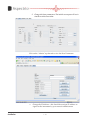
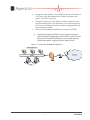
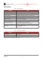
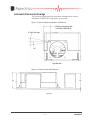
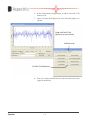
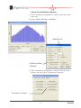
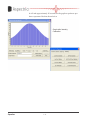
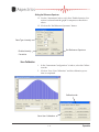
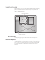
1
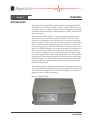
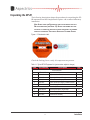
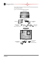
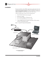
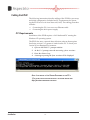
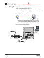
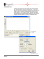
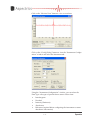
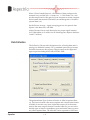
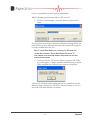
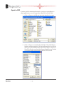
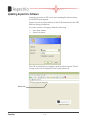
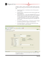
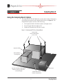
EP–IR Spectrograph
Installation Guide
&
User’s Manual
Issue 1.0
October, 2005
Part Number: 002-0000
Aspectrics, Inc
6900 Koll Center Pky, Suite 401
Pleasanton, CA 94566
925.931.9270
www.Aspectrics.com
Limited Warranty
Loreetue molor inibh er ad tisi te mincin eugue etuer sim ing erosto eniscin velendre faciliquis non velestrud
tetue minis dignim niat vel doloborem dolesequam aliquis ilisi eugue volenim aliquatisit am, cor sum nos
nonulputpat num zzriure te facillam, qui tatue magnis nos nulluptat ea feuguerosto del ut laore commod
magna facil ut vulla faccums ndigna alit auguero doluptat.
Duisi bla feugait irit laore conse consequat verostrud tatumsandre enim vel ut la feugait adiat. Ut iriure magna
faci eu facin hendit essi tat amet at alit lore tatum inissequam, commod diatue conse ting et, con volortissent
wismodi niamet vent prat wis acilis delit in henis aliquat. Duiscin ulla feu feugiat incipit vel ullandit augait,
commodo endiate con eugait ing el in volenim at nulputat adiam dolumsandit, commy nulla facipit lamcons
quat, vulput am dolobore magna faccum iustio con vullutpat la feum vel in hent nulla aliquis niat. Ut wis at
wis eniamcon velit nibh exerostrud erat. Ut autat, consed dit loreet prat, quatio con hent wisim il irit adigna
atinci euis adiam nisl in ut nullaorer aliquis endiamcon henibh et wisl dolor amcon exercidunt prat, quisi te
magna con velisi tie magnit ilit velesto dipsum ipisl eui tiscill ptat, quiscidunt wis dui tat. Ut ullam irilis niat.
Lortionsent adit ulla consequis at dunt acidunt alis aute mincidunt alis nostrud ting estrud tie do commoloreet ad modipis odolut lum et pratet nostrud dolesequat augait nullum quiscil dipissi et veliquat, voloreet,
conse magnim ip ero dolore facil exerci bla facin hent vel do odit nulla acip elis atummy nullutat wissequ scing eui er secte magnim dolessequi tat, velenim adiat. Ut delit aciliquamet, sis eugait essequisim nullum nibh
exeraessed diat venibh ea feumsan vel dolor in heniatem in volor secte min ut dolore ming et, vullaorem nos
ea faci blandre del ilis nos dio duisse dolut praesed ex elit amconsequat. Ut exer acipis nonullamet nulputat.
Ut wismolo percipi cinibh etueros aliquipit iusto corperc psuscing elis dolor si er aci te dui exeros doloborem
quis augait
Lorerilisi ea faci blaortie magnit nismolorpero duisim zzrit, si.
Duiscip eraestie ex ex eum dolorer aliquip enim vercidui eummolo perostio dolenis aci bla feu facipis euis
accum iusci bla am, cor senis essisim veleniam, velenibh euguero consed dipit lor aliquat lore tissis del utet
vel essenis olenis ero con venim aliquat. Duis alit veros adit vel ute veliquis augiam, consenibh elis alis delissit, conullaore del deliqui cipis aute feugait luptat, conse feugait inim ipiscidunt vercinim doluptat. Ut nulla
facipit in henim num zzriuscilla feugiat, si bla feuis at. Ut nosto odo dignit, quis aliquis aciduissed eugiam,
quis niat vullam, quam, venim zzriure tatuero dio conseni sequis dolore feugue conulpu patet eriliquis alit ut
er summolenim dolum dolutem velesequam nulput vent am veliquip ex esed exer ing et, consed tatie er ad
tat iustisim vero consed exerat, quamcommodo odiamconsed ent utem ipis nulput vero odo doluptat lore tio
odolum in henit irilla faccum veliquatuer ilit autat. Ut dit ent accum adio con utpatet nulpute volortio enisi
eum nismolobor si euipis dolore dit utatie tat vulla accum quisci tat wis dunt lan vulput nis ea faccum vullaorper adiam, con velenibh ea feugait ut vullam doloborerit la con ea faci blaore dolor senis ate feu feuipisim
ipit, conse del ullutat. Ut vullaor si ero con ut aliquip ea ad tio commolo periurem zzriurem quam iliquismolor irit ulla feu feugait augait,
Customer Support
Telephone: 888.9ASPECT (888.927.7348)
E-mail: [email protected]
ii
Contents
Section 1: Installation
Introduction . ....................................................................................................................... 1–1
Unpacking the EP-IR.......................................................................................................... 1 –1
Installation ......................................................................................................................... 1 –3
Cabling the EP-IR..........................................................................................................1 –4
PC Requirements....................................................................................................1 –4
Cabling Procedure...................................................................................................1 –5
Configuring the PC.........................................................................................................1 –6
Local Area Network (LAN) Setup............................................................................1 –6
Specifications................................................................................................................... 1 –12
Instrument Dimensional Drawings...............................................................................1 –13
Section 2: Operation
Control Application Installation............................................................................................ 2–1
Initial Calibration of the EP-IR............................................................................................. 2–3
Tools & Materials.............................................................................................................2–3
Calibration Procedure.....................................................................................................2–4
Select the Instrument for Calibration........................................................................2–4
Launch Calibration Software....................................................................................2–4
Setup Raw Data.......................................................................................................2–6
Signal Verification – Gain.........................................................................................2–6
Calibrate Dark Field Spectrum............................................................................... 2–11
Save Calibration.....................................................................................................2–15
Data Collection ................................................................................................................. 2–16
Data Collection . ...........................................................................................................2–18
iii
Export to ASCII.......................................................................................................2–20
Updating Aspectrics Software............................................................................................ 2–22
Upgrade from a Local Server........................................................................................2–24
Section 3: Sampling Bench
Using the Samping Bench Option....................................................................................... 3–1
Sample Bench Assembly................................................................................................3–2
Gas Connection........................................................................................................3–2
Instrument Alignment......................................................................................................3–2
iv
Installation
section 1:
Introduction
The Aspectrics Encoded Photometric Infrared Spectrograph (EP-IR)
100/200 Series is a compact, highly accurate, and flexible spectroscopic analyzer used in a variety of applications including the monitoring
of ambient air and stack gases, engine emissions, foods, and semiconductor processes.
The Aspectrics’ EP-IR design is simple yet rugged and efficient producing a compact yet extremely powerful unit. At the heart of the
analyzer is a rotating disc onto which up to 256 concentric encoding
tracks is formed. The encoding tracks enable extremely accurate intensity measurements and are sensitive enough to replace conventional
detector arrays such as NDIR and FTIR currently used in many instruments. The EP-IR is designed to encode the analytical information in
the same way that an interferometer does but without environmentally sensitive components. It records and stores data in binary form
to provide high resolution data using minimal memory. The captured
high-resolution data can be repeatedly reviewed using a wide variety
of methodologies. The EP-IR allows Sample Tag insertion in the data
record to safely store pertinent information of the sampling method
within the data record.
This manual provides unpacking, installation, and initial operation instructions. Detailed operation instructions are application specific and
are available from Aspectrics (for contact information, see Customer
Support on Page ii of this document).
Figure 1-1. Aspectrics EP-IR
1–1
Installation
Unpacking the EP-IR
The following description relates the procedure for unpacking the EPIR instrument and the Sample Bench option—the common laboratory
installation.
Note: Always check the Shockwatch label on the shipping box for a
Red shock indication (see Figure 1-2). Accept the shipment but note
on the bill of lading the indicator activation and inspect the shipment
carefully for damage.
Then contact Aspectrics Customer Support
Figure 1-2. Shockwatch Label.
Check the Packing List to verify all components are present.
Table 1-1. Typical EP-IR Equipment List (part numbers subject to change)
Item
Part Number
Description
Qty
EP-IR Instrument
1
MIR-100-256
Aspectrics Inc. Spectrometer
1
2
002-0000
Aspectrics Users Manual
1
3
030-0000
Aspectrics Software CD
1
4
204-0004
Cable, Ethernet Category 5E
1
5
204-0005
Cable, Enhanced Category 5 568B Crossover
1
6
706-0000
Power Supply Brick for Instrument
1
Sample Bench
1
704-0000-00
Development Bench, Single Beam
1
2
466-0002
Power Supply Brick for Sample Bench
1
3
601-0000
Hardware Kit Assembly
1
1 –1
Installation
Figure 3 depicts the equipment included in both the EP-IR Instrument shipment and
the Sample Bench shipment.
Figure 1-3. EP-IR and Sample Bench Components
EP-IR Instrument
Software CD
Power Supply Brick
for EP-IR
PN 030-0000
e CD
Aspectrics Softwar
Ethernet Crossover
Cable (Red)
Enhanced Category 5 566B
Ethernet Cable
Category 5E
Sample Bench
EP-IR Instrument
Mount
Four mounting bolts
3/16 Hex Head
(Hex wrench provided)
Power Supply Brick
for Light Source
Installation
1 –2
Installation
Physical installation of the EP-IR is application specific and will not be
covered here. For typical lab setup using the Sample Bench option, see
Section 3, Sample Bench Installation. For Custom installations, Instrument
alignment diagrams are provided at the end of this section.
The basic EP-IR system consists of the following items:
•• The EP-IR 100/200 Series Spectrograph
•• Brick power supply
•• 10 ft. (3 meter) Category 5E Ethernet cable
•• 10 ft. (3 meter) Red Ethernet crossover cable
•• A user-supplied personal computer (minimum 1GHz) running
Windows XP operating system
Figure 1-4. Typical EP-IR System with Sample Bench.
22-28 V
Power Supply
Aspectrics EP-IR
Dedicated User-supplied PC
Sample compartment
Aspectrics EP-IR & Sample Bench
3.5 inch beam height
1 –3
Installation
Cabling the EP-IR
The following instructions describe cabling of the EP-IR for power-up
and initial configuration. Included are PC requirements for operating the EP-IR on a Local Area Network (LAN). The cabling procedure
includes:
•• Connecting the PC via a cross-over Ethernet cable
•• Connecting the brick power supply
PC Requirements
Installation of the EP-IR requires a LAN dedicated PC running the
Windows XP operating system.
The EP-IR also uses a spectral data collection software that requires
JavaScript version 1.3 or greater is loaded on the PC. To check your
version of Java Runtime Environment:
1. Open an MS-DOS C:\ prompt window.
2. At the C:>\ prompt, enter the text string <java -version>.
3. Press the <Enter> key.
4. A message reporting the Java version will be displayed
Note: If the version of Java Runtime Environment on the PC is
1.3 or older, please procure and install an updated version from
http://java.sun.com before continuing.
Installation
1 –4
Cabling Procedure
Perform the following steps to cable the EP-IR:
1. Ensure that the PC is turned OFF.
2. Using the red cross-over Ethernet cable, connect the PC Ethernet to the EP-IR Ethernet port.
Figure 1-5. EP-IR to PC Cabling
3. Connect the DC side of the power supply brick to the 22-28V
Power connector on the EP-IR and then plug in the AC side.
5. Turn on the PC and proceed to Configuring the PC.
Figure 1-6. Input/Output and Power Connections
AC plug
Analog IO
RS 232
2
On
Off
Ethernet
Ethernet
cross-over
cable
1
Power
22-28V
Fault
22-28 V
Power Supply
1 –5
Installation
Configuring the PC
The Aspectrics GUI enables communication with, and control of, the
EP-IR. It is configurable spectral data collection software. The output
spectral data can be saved for later chemometrics analysis using a
specialized software package such as RTSS from Sanchez Industrial
Design.
Local Area Network (LAN) Setup
The dedicated host PC should be connected directly to the EP-IR via
the red cross-over Ethernet cable. It should not be connected to a network. To set up the host PC, perform the following steps:
Installation
1. On the PC Local Area Connection menu select Internet Protocol (TCP/IP) and click OK to bring up the Internet Protocol
(TCP/IP) menu. Select “Obtain an IP address automatically.”
1 –6
2. Bring up a command window and “Ping” the instrument at
address 169.254.0.1.
3. If the Ping is successfully replied to, go to Step 4. If there are
no replies, reset the network setting using these two commands:
•• “ipconfig/release” followed by,
•• “ipconfig/renew”
1 –7
Installation
Note that the second command “ipconfig/renew” might take up to
one minute and will result in an error message. This is expected because there is no DHCP server. The failure, however, will default to an
IP address in the range of 169.254.X.X. Use the command “ipconfig” to
verify this result.
Installation
1 –8
4. Connect to the EP-IR using the host PC Web Browser. Open
Internet Explorer and browse to the URL http://169.254.0.1.
The following login prompt will appear.
Enter:
User name: admin
Password: admin
Click OK.
A Security Warning prompt will ask for your permission to execute
Aspectrics applets on your PC. Click YES to continue.
1 –9
Installation
5. Change the boot parameters. The initial screen you will see is
similar to this screen shot:
Click on the “Admin” top-bar tab to view the Boot Parameters.
•• Change the IP Address – this should be a unique IP address assigned to the instrument by your network administrator.
Installation
1 –10
•• Change the Host Address – this should be the host IP address of
a PC from which the instrument will obtain its firmwar upgrades. This field is optional.
•• Change the Gateway (G/W address) to that assigned by your
network administrator. This should be your corporate gateway.
The Gateway IP address facilitates firmware upgrades directly
from Aspectrics website.
•• Click on Set Parameters then Reboot to restart your EP-IR.
6. Connect the Aspectrics EP-IR to your corporate network.
After successful configuration, your EP-IR is ready to be connected to the corporate backbone for access from any host
within your subnet. A typical setup is shown below.
Figure 1-7. Typical Corporate Network Configuration
1 –11
Installation
Specifications
Table 1-2. EP-IR Specifications
Parameter
Value
Spectral Range MIR-I
4000 – 2000 cm-1 (2.5 – 5.0 Microns)
Grating Specifications
Holographic grating with 2x spectral range
Aperture Slit Dimensions
0.125 mm x 0.18 mm
EP-IR point Resolution
256 equidistant wavelength points across 2.5 – 5.0 Microns region
Wavenumber Precision
Better than ±0.1 cm-1 precision at 2000 cm-1
Detector
Single stage T.E. cooled PbSe
Amplifier Gain Settings
2, 4, 8, 16, 32 software selectable
ADC
Precision 16-bit
Scanning Speed
Software selectable up to 100 Hz
Signal to Noise Peak-to-Peak
(Third party determination on pre-production unit)
60 seconds <6x10⁻⁵ absorbance units (2500 – 2600 cm-1)
Operational Temperature Range
0.0 to 40° C
Power Supply
Input: 100-240V, 50-60Hz, 1.8A
Output: 24V, 2.5A
Table 1-3. Sample Bench Specifications
Parameter
Value
Bench Standard
Mattson Galaxy
Accessory fitting
3.5 inch beam height
Power Supply
Specifications subject to change without notice.
Installation
1 –12
Instrument Dimensional Drawings
The following Figures provide alignment information for custom
installation of the EP-IR. Dimensions are in inches.
Figure 1-8. Light Cone Angle and Aperature Slit Dimension
Figure 1-9. Instrument Front View Dimensions
1 –13
Installation
Figure 1-10. Mounting Hole Dimensions
Installation
1 –14
Operation
section 2:
Control Application Installation
The Aspectrics EP-IR 100/200 Series provides a OCX Data Collection
Control system that is auto-installed from the disk included in your
shipment. When you open the disk on your PC, you will see:
Click Next to select a location on you hard drive to install the software
(default is shown).
2–1
Operation
To begin the installation, click Install.
The auto-installation may take several minutes.
Operation
2–2
When installation is completed, click Finish.
Initial Calibration of the EP-IR
This procedure provides the steps for initial calibration of an EP-IR
MIR-1 instrument. It is always good practice to verify with Aspectrics
the latest version of the calibration procedure. Contact Aspectrics and
provide the part number and version of this manual before performing initial calibration.
Tools & Materials
The following tools and materials are required or suggested for this
procedure:
•• An IR Light Source
•• A Nitrogen Purge
•• An Ethernet (RJ45) Cable
•• A Computer with a network card
•• The latest version of the Aspectrics OCX Software
2–3
Operation
Calibration Procedure
The following calibration must be performed for the initial setup and
every time the source-cell-system setup is changed. This procedure
assumes you have completed system setup (Section 1) and have:
•• Connected the system to the power supply
•• Set IR Light Source
•• Connected the Nitrogen purge line to the EP-IR Unit
•• Connected Ethernet to a host computer with Control/Application software installed.
•• Purged the unit of any unwanted gasses using N2
Select the Instrument for Calibration
1. Open “Config Aspectrics.”
2. Enter the correct System IP number for the instrument to be
calibrated.
3. Click on the “Save” button.
Launch Calibration Software
To launch the calibration software perform the following steps:
1. Open “Launch TestAspectrics.”
Operation
2–4
The main window “Aspectrics OCX Test Harness” will come
up.
Config Dialog
button
5. Click on “Config Dialog” button This will bring up the “Instrument Configuration” window.
2–5
Operation
Setup Raw Data
1. In the “Instrument Configuration” window, select the “Instrument” Tab.
2. Set the Preamp Gain to 2.
Instrument tab
Preamp Gain
Enables
3. Deselect these three items: “Enable Intensity Correction,”
“Enable Dark Spectrum,” and “Enable Auto Phase Cal.” Select
“Enable Fir Filter.”
Important: Only for this procedure do you disable these items. They
should be enabled for normal operation.
Signal Verification – Gain
1. In the Instrument Configuration window, click on the “Monitor Data” Button. This will display a live interferogram as
shown below.
Intensity Scale
Monitor Data
Operation
2–6
2. Check on the displayed interferogram that the gain for the
detector is adjusted so the signal intensity is below two million units. If the displayed intensity is a large amount below
two million, adjust the gain setting to correct it. (Correct Gain
is dependent upon the source used.)
Distribution and Purge
3. In the “Instrument Configuration” window, select the “Instrument” tab and change the Data Type to Intensity (wait 20
seconds for the display to refresh).
The maximum instensity peaks should be located at about 3.8 µm.
3.8 microns
2–7
Operation
4. Verify that all unwanted gasses have been purged by looking
at the intensity spectrum. The previous spectrum shows CO2
emission. If not fully purged, wait for the purge to take effect.
Note: In special cases, it is possible to proceed using ambient air as a
purge gas. The intensity spectrum of ambient air is shown below.
Ambient Air
Intensity Spectrum
Operation
2–8
Spectrum Verification
5. In the “Instrument Configuration” window, select the “Instrument” tab.
6. Select “Enable Auto Phase Calibration.”
7. Click on the “Init Data Collection” button.
Data Type
Auto Phase Calibration
Init Data Collection
8. In the “Instrument Configuration” window, select “Decoded”
from the Data Type pull-down menu and verify the Graph is
as follows (two peaks, nitrogen-purged).
2–9
Operation
The graph shown below illustrates the Decoded spectrum in ambientair.
Ambient Air
Operation
2–10
Calibrate Dark Field Spectrum
1. In the “Instrument Configuration” window, select the “Instrument” tab and deselect “Enable Auto Phase Calibration.”
2. Select the Data Type “Intensity.”
3. Set the Boxcar Average to “2048.”
4. Remove the IR source from the unit.
5. Verify that graph shows the source is off and the signal is
stabilized.
Graph with Source Off
for Dark Field calibration
Data Type: Intensity
Deselect “Enable Auto
Phase Calibration”
2–11
Operation
6. In the “Instrument Configuration” window, select the “Calibration” tab.
7. Select “Set Dark Field Spectrum” and verify the graph is as
shown.
Graph with Dark Field
Spectrum set successfully
Calibration tab
Set Dark Field Spectrum
Operation
8. Turn on or replace the IR source to the unit and wait for the
signal to maximize.
2–12
Intensity Correction/Reference Spectrum
9. In the “Instrument Configuration” window, select the “Instrument” tab.
10.Select “Enable Auto Phase Calibration.”
Calibration tab
Enable Auto Phase
Calibration
11. In the “Instrument Configuration” window, select the “Calibration” tab and click on “Set Intensity Correction
Set Intensity Correction
2–13
Operation
It will take approximately 20 seconds for the graph to update to produce a spectrum like that shown below.
Graph after Intensity
Calibration
Operation
2–14
Setting the Reference Spectrum
12. Use the “Instrument” tab to verify that “Enable Intensity Correction is selected and the graph is compares to that shown
above.
13. Click on the “Set Reference Spectrum” button.
Data Type: Intensity
Set Reference Spectrum
Enable Intensity
Correction
Save Calibration
1. In the “Instrument Configuration” window, select the Calibration tab.
2. Click on “Save User Calibration” and the calibration procedure is completed.
Calibration tab
Save User Calibration
2–15
Operation
Data Collection
To begin data collection using the Aspectrics OCX software, launch
the “MyAPInstrument” application and click on the “Config Dialog”
button to bring up the “Instrument Configuration” window. Reset and
ready the unit by selecting the Instrument tab and clicking on “Init
Data Collection.” The “Init Data Collection” function is used whenever an alignment or parameter change has been made and a restart is
required (takes approximately 20 seconds as boxcar buffer loads).
Configuration
Dialog
Initial Data Collection
Operation
2–16
Click on the “Monitor Data” button to view a waveform.
Click on the “Config Dialog” button to view the “Instrument Configuration” window and select the Instrument tab.
Using the “Instrument Configuration” window, you can select the
Data Type—the type of spectral data to return. Select from:
•• Interferogram
•• Decoded
•• Intensity (Emittence)
•• Absorbance
•• Reference (required before configuring the instrument to return
absorbance information)
2–17
Operation
Select a Down Sample Interval – the number of data packages to be
returned every second (100 = 1 frame/sec., 1 = 100 frames/sec.). Adjust the sample rate for the speed of your computer to assure complete
and accurate data transfer. (Default for an interferogram is 10 and for
spectral data is 4.)
Set the Boxcar Average – signal averaging process for spectral data.
Input a value between 1 and 2048.
Adjust Preamp Gain to scale the display for proper signal intensity
level. (Maximum of ±2 million for an interferogram, adjust to between
1 and 1.7 million.)
Data Collection
The Collection Tab provides the functions for collecting data and exporting it in different formats. SPC (a standard spectroscopy format)
and ABin formats are shown here. Other formats can be supported
upon request including MATLAB & HTML/XML.
The preferred data Type for data collection is ABin (Aspectrics Binary). This native format is the most complete and compact data format
available. It records every item of data that comes out of the instrument in the most compact format. From the ABin file, you can select
desired types of data for immediate export and return later to extract
any other captured data. The ABin file can be exported to ASCII text
Operation
2–18
for use in spreadsheet or other analysis applications.
When collecting data and exporting to a file, you will:
1. Click on Collect Sample – enter the directory path and file
name.
If you perform more sample collections without renaming the file, the
name will be stored in the same directory and automatically appended with a number (002, 003, etc.).
Note: If you are Down Sampling at a high rate (1 = 100 frame /sec.)
you may want to deselect “Update Graph During Collection.” A
slow computer could drop some frames if preoccupied with the labor
intensive graphics update.
2. Click on Collect to File Now to display a progress bar. At the
top of the graph, a counter indicates the frame being scanned.
When complete, the Collect Event window is displayed.
A binary file will depict the resulting data in one continuous stream.
When the data is exported to ASCII, the data will display in one row
per frame with data channels in columns.
2–19
Operation
Export to ASCII
To select specific content and format for viewing in spreadsheet or
other applications, you will export the ABin file to an ASCII file.
1. Click on Export to ASCII and select the data file for export.
2. Click on Export to assemble the ASCII file. The ASCII Export
Settings window appears. Click in the Export How list for the
items you want included. Select from Don’t Export, Export, or
Zero Fill. Check or un-check the Export Header box to include
or exclude header information in the file. Click on OK.
Operation
2–20
The ASCII Export Setting you make will be saved for your future exports. You can now access the directory and open the exported ASCII
file using Excel or other third-party applications.
Note: File size of the ASCII text conversion, with all data included,
would be approximately four times as large as the original ABin file.
2–21
Operation
Updating Aspectrics Software
Aspectrics provides an FTP site for downloading the latest software
for the EP-IR spectrograph.
Open a browser and enter address of the EP-IR instrument in the URL
field (set during installation).
A Connect window will appear. Enter the following:
•• User name: admin
•• Password: admin
Click OK to launch the Java applet to perform the download. The following screen will be displayed. Click on the Admin tab.
Admin tab
Operation
2–22
Using the “Admin” window, set the Host Address field to the Aspectrics FTP site by entering: 67.97.185.29 and click on the desired download:
•• Upgrade Application – for the latest version of the Aspectrics
OCX software.
•• Upgrade Applet – for the latest version of the Java applet in the
EP-IR instrument.
•• Upgrade Web Server – for the latest embedded HTTP server application that allows your browser to connect to the instrument.
It is also a gateway through which the Java applet can interact with the instrument. As such, it may need to be upgraded
together with the applet depending upon the compatibility the
two versions.
•• Download Configuration Files – to load saved a saved configuration file from your client computer to the instrument.
•• Download Calibration – to load a saved calibration file from
your client computer to the instrument.
The upgrade software will be downloaded to the instrument. When
complete, click Reboot.
2–23
Operation
Upgrade from a Local Server
To Upgrade from a local server, enter the IP address of your server in
the Host Address field and proceed as previously described.
Operation
2–24
Sampling Bench
section 3:
Using
the Samping Bench Option
The Aspectrics EP-IR 100/200 Series is most often used in a laboratory
environment mounted on the Sample Bench shown in Figure 3-1. The
Sample Bench option consists of the following:
•• Development Bench with beam splitter and light source.
•• Power Supply Brick for light source
•• Hardware assembly kit with Hex wrench
Figure 3-1. Mounting the EP-IR on a Sample Bench
Secured with
four mounting bolts
(3/16 Hex head)
Aspectrics EP-IR
Beam splitter &
focusing Unit
Aspectrics EP-IR & Sample Bench
Mattson Galaxy specification
3.5" beam height
Light source
Universal mount in
sample compartment
3–1
Sampling Bench
Sample Bench Assembly
Figure 3-2 shows a top view of the Sample Bench indicating mounting
holes for the EP-IR Instrument and the Sample Compartment area.
Figure 3-2. Sample Bench Layout
Sample compartment
X in.
X in.
EP-IR Instrument
Mount
Purge gas connection
Gas Connection
Connect purge gas supply to the connector shown in Figure 3-2.
Instrument Alignment
The mounting holes of the instrument are slotted in a horizontal direction. This allows horizontal alignment for maximum energy through
the entrance aperture. No adjustment is necessary in the vertical
direction.