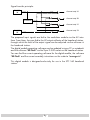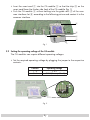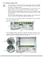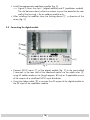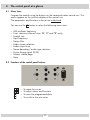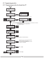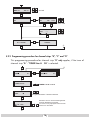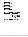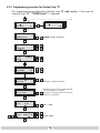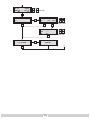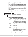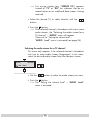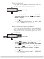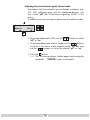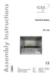
1
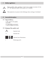
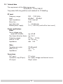
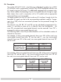
HDC 470 CI AV Notes on the Assembly Instructions. As well as this supplementary Assembly Instructions, the Assembly Instructions for the STC 160 apply. English Assembly Instructions STC 160 Head-End Station QPSK AV module GSS Grundig SAT Systems GmbH Beuthener Strasse 43 D-90471 Nuremberg Phone: Fax: Email: Internet: +49 (0) 911 / 703 8877 +49 (0) 911 / 703 9210 [email protected] www.gss.tv Contents 1 Safety regulations........................................................................................................3 2 General information....................................................................................................3 2.1 2.2 2.3 2.4 Scope of delivery..........................................................................................3 Meaning of the symbols used..........................................................................3 Technical data..............................................................................................4 Description...................................................................................................5 3 Installation..................................................................................................................7 3.1 3.2 3.3 3.4 Retrofitting a CA module................................................................................7 Setting the operating voltage of the CA module................................................8 Installing the digital module............................................................................9 Connecting the digital module......................................................................10 4 The control panel at a glance..................................................................................... 11 4.1 Menu items................................................................................................. 11 4.2 Functions of the control panel buttons............................................................ 11 5 Programming............................................................................................................ 12 5.1 Preparation................................................................................................. 12 5.2 Programming procedure............................................................................... 13 5.2.1 Programming procedure for channel strip “A” ...................................... 13 5.2.2 Programming procedure for channel strips “B”, “C” and “D”...................14 5.2.3 Programming procedure for channel strip “D”.......................................16 5.3 Programming the digital module....................................................................18 Selecting the module / channel strip....................................................18 5.3.1 Programming channel strip “A”............................................................19 Setting the LNB oscillator frequency.....................................................19 Configuring the CA module, displaying card information.......................20 Setting the input symbol rate...............................................................20 Setting the input frequency.................................................................. 21 Setting the station filter.......................................................................22 Selecting the audio stream for a TV channel.........................................23 Setting the volume level ....................................................................24 Setting the identification of the stereo / dual tone..................................24 Adjusting the picture format signal, teletext mode..................................25 Activating teletext subtitle pages and setting the standard.......................26 Storing data......................................................................................27 5.3.2 Programming channel strips “B”, “C” and “D”.......................................28 Selecting a tuner................................................................................28 Setting the station filter.......................................................................29 5.3.3 Programming channel strip “D”...........................................................30 Selecting a tuner................................................................................30 Setting the LNB oscillator frequency..................................................... 31 6 Final procedures........................................................................................................ 31 -2- 1 Safety regulations Please read the safety regulations listed in the assembly instructions for the STC 160 head-end station which pertain to this module. Take precautions to prevent static discharge when working on the device! 2 General information 2.1 Scope of delivery 1 HDC 470 CI AV module 1 AV cable 1 CD (assembly instructions) 1 Brief Assembly Instructions 2.2 Meaning of the symbols used Important note —> General note – – • / / Optional use of the buttons Performing works -3- 2.3 Technical data The requirements of the following are met: 2006/95/EC, 2004/108/EC The product fulfils the guidelines and standards for CE labelling. HF input: Frequency range: Level: Input impedance: Return loss: Input data rate: Remote power supply: 950 … 2150 MHz 60 dBμV … 80 dBμV 75 Ω, nominal 8 dB 1 … 45 MSymb 12 V / 350 mA (switch-off at short-circuit) Output specifications: Audio Noise voltage ratio rated (DIN 45633): typ. 60 dB Non-linear distortion factor: typ. 0.6 % Frequency range: 20 Hz … 15 kHz Level at -12 dB: typ. 500 mVrms Impedance: max. 1 kΩ Video Signal-to-noise ratio: Level (75 Ω): Impedance: Connections: SAT inputs: Connection strip (20-pin): AV output: 58 dB (rated) typ. 1 Vpp 75 Ω 2 F-sockets For supply voltages and control circuits 26-pin socket -4- 2.4 Description The module HDC 470 CI AV, in the following called digital module, has a QPSK AV converter which simultaneously converts four QPSK modulated channels into AV signals using two SAT tuners. It is additionally equipped with a common interface, which enables the decoding of up to 4 encrypted channels through a single data stream when used in conjunction with a CA module and an appropriate smart card from a service provider. The digital module has two SAT inputs and one AV interface, through which the decoded AV signals are fed to the corresponding modulator module. Components (e.g. LNB) which are connected upstream can be powered through the SAT inputs. The channel strips “A” “B”, “C” and “D” can be individually programmed. This means it is possible to select up to 4 channels from two transponders. Via tuner “A” encrypted and unencrypted channels can be received. Tuner “D” is prepared to receive unencrypted channels only. The following tables show the possible allocations of the selectable number of channels to the tuners. For example, if three unencrypted channels from tuner “A” will be used, one unencrypted channel from tuner “D” can be used. If , e.g. two unencrypted channels from tuner “A” will be used, two unencrypted channels from tuner “D” can be used. Quantity of unencrypted channels Tuner “A“ 3 2 1 Tuner “D” 1 2 3 For example, if four encrypted channels from tuner “A” will be used, no channel from tuner “D” can be used. If , e.g. two encrypted channels from tuner “A” will be used, two unencrypted channels from tuner “D” can be used. Tuner “A“ (encrypted channels) Tuner “D” (unencrypted channels) 4 3 2 1 0 1 2 3 Quantity of channels -5- Signal transfer principle: TUNER "A" Channel strip "A" Channel strip "B" CA module Channel strip "C" Channel strip "D" TUNER "D" The prepared input signals are fed to the modulator module via the AV interface. From there, they are fed to the HF output collector of the head-end station, through which the level of the output signal can be adjusted via the software in the head-end station. The digital module operating software can be updated using a PC or notebook and the software “BE-Flash” via the 9-pin D-SUB socket on the head-end station. You can find the current operating software for the digital module, the software “BE-Flash” and the current assembly instructions on the website “www.gss.tv”. This digital module is designed exclusively for use in the STC 160 head-end station. -6- 3 Installation Caution – Ensure the head-end station is mounted so it will not be able to vibrate. Avoid, for example, mounting the head-end station onto a lift shaft or any other wall or floor construction that vibrates in a similar way. – Before installing or changing a module, switch off the head-end station or unplug the power cable from the mains power socket. Take measures to protect against ESD! 3.1 Retrofitting a CA module The digital module is equipped with a common interface. It allows you to connect a CA module for various encryption systems and service providers. Encoded channels can only be decoded with a CA module suitable for the encoding system and the corresponding smart card. The smart card contains all the information for authorisation, decoding and subscription. Caution – Check with the distributor or manufacturer of the CA module to be used to ensure that it is suitable for decoding 2 or more channels. – The hardware and software of the module HDC 470 CI AV have been thoroughly prepared and tested. – Any changes made by program vendors to the structures in the program data might impair or even prevent this function. – When working with the CA module, please read the corresponding operating manual from the respective provider. -7- • Insert the smart card 1 into the CA module 2 so that the chip 3 on the smart card faces the thicker side (top) of the CA module (fig. 1). • Push the CA module 2 without canting into the guide rails 4 of the common interface slot 5 according to the following picture and contact it to the common interface. Fig. 1 3.2 Setting the operating voltage of the CA module The CA modules can require different operating voltages. • Set the required operating voltage by plugging the jumper to the respective contacts: Contacts 1-2 3-4 Operating voltage +5V + 3.3 V (Factory default) Fig. 2 -8- 3.3 Installing the digital module – If a CA module is used, check that the plug contacts of the CA module are tightly seated in the terminal strip on the digital module and make sure there is a reliable contact. – Always position modules which belong together next to each other. The digital module must be installed to the left of the modulator module. – When installing the digital module, make sure that it is inserted in a long numbered groove in front of a contact strip on the board at the rear wall of the housing. The shorter not numbered grooves without a contact strip on the board at the rear wall of the housing are for add-on modules only. • Open the housing of the head-end station in accordance with the assembly instructions for the STC 160. • Open the locking device 1 in the direction of the arrow (fig. 3). Fig. 3 • Insert the digital module in grooves A and B of an open slot left to the associated modulator module and gently slide it into the head-end station until it makes contact with the board on the rear wall (fig. 4). Fig. 4 -9- • Install the appropriate modulator module (fig. 5). —> Figure 5 shows the slots 1 (digital module) and 2 (modulator module). The slot between them (without a contact strip on the board at the rear wall of the housing) is for an add-on module only. • After installing the modules close the locking device 1 in direction of the arrow (fig. 5). 3.4 Connecting the digital module ! " Fig. 5 • Connect SAT-IF inputs C of the digital module (fig. 5) to the preinstalled F terminals in the rear wall of the head-end station via the cable inlets E using HF cables made on-site (length approx. 80 cm) or if applicable to one of the outputs of a retrofitted SAT-IF input distributor. • Using the ribbon cable D to connect the AV output of the digital module to the AV input of the modulator module. - 10 - 4 The control panel at a glance 4.1 Menu items Program the module using the buttons on the head-end station control unit. The menus appear on the two-line display of the control unit. The parameters and functions to be set are underlined. You can use the M button to select the following menu items: – LNB oscillator frequency – Tuner selection (channel strips “B”, “C” and “D” only) – Symbol rate – Input frequency – Station filter – Audio stream selection – Audio output level – Stereo decoding / audio type selection – Picture format signal (WSS) – Teletext subtitle page – Store 4.2 Functions of the control panel buttons M S – To – To S – To M – To move the cursor adjust values and functions store the programmed data switch to the next menu - 11 - 5 Programming 5.1 Preparation • Connect the digital module to a programmed modulator module. • Connect the test receiver to the HF output on the modulator module. • Adjust the test receiver to the output channel of the channel strip to be set: Digital module – channel strip “A” —> modulator module – channel strip “A”, Digital module – channel strip “B” —> modulator module – channel strip “B”, Digital module – channel strip “C” —> modulator module – channel strip “C”, Digital module – channel strip “D” —> modulator module – channel strip “D”. - 12 - 5.2 Programming procedure 5.2.1 Programming procedure for channel strip “A” Ein/On SETUP BE160 V6 Bx 1A QUAD Bx 1B QUAD ORF2 V1 ORF1 V1 M / / Bx 1A Bx 1A LNB 10600 MHz MENU 1/6 Information *) > M / / M *) Die angezeigte Information ist abhängig vom verwendeten CA-Modul The information displayed is dependent on the CA module used Bx 1A SYMBOL / / FREQ / / 22000 M Bx 1A 12691 MHz -0.8 M Bx 1A 02/19 * TV ORF2 / Programmauswahl / Channel selection M AUDIO Bx 1A / 01 / 02 “deu” Das Menü wird nur bei Auswahlmöglichkeit mehrerer Begleittöne angezeigt. This menu is only displayed if several audio streams are selectable. M Bx 1A AUDIO Level 0 dB / -26 … 6 dB / / norm / swap M / Bx 1A AUDIO mpeg DUAL norm mpeg / VPS M - 13 - Bx 1A VIDEO WSS off TXT on / / on / off M Bx 1A SUBTITLE 150 txt M west txt / off west / east M –– dvb dvb / off M MEMORY S => STORE M / / SUBTITLE Bx 1A Bx 1A / / SUBTITLE Bx 1A off CANCEL S 5.2.2 Programming procedure for channel strips “B”, “C” and “D” This programming procedure for channel strip “D” only applies, if the tuner of channel strip “A” - “TUNER Line A CA” is selected. Bx 1B QUAD ORF1 V1 Bx 1C Das Erste QUAD V1 M Bx 1B INPUT / TUNER Line A TUNER Line A / Line D M Bx 1B 01/19 * TV ORF1 / Programmauswahl / Channel selection M AUDIO Bx 1B 01 / 02 “deu” / Das Menü wird nur bei Auswahlmöglichkeit mehrerer Begleittöne angezeigt. This menu is only displayed if several audio streams are selectable. M d - 14 Bx 1B AUDIO Level 0 dB / -26 … 6 dB Bx 1B AUDIO mpeg DUAL norm / / norm / swap / / on / off M / mpeg / VPS M Bx 1B VIDEO WSS off TXT on M Bx 1B SUBTITLE SUBTITLE Bx 1B off 150 txt M dvb SUBTITLE –– M MEMORY S => STORE M / / txt / off west / east M Bx 1B Bx 1B west / / dvb / off CANCEL S - 15 - 5.2.3 Programming procedure for channel strip “D” This programming procedure for channel strip “D” only applies, if the tuner of channel strip “D” - “TUNER Line D” is selected. Bx 1D QUAD Bx 2A 4AV STEREO V1 C27 Das Erste M Bx 1D INPUT / TUNER Line D TUNER Line D / Line A CA M LNB / / SYMBOL / / FREQ / / Bx 1D 10600 MHz M Bx 1D 27000 M Bx 1D 11835 MHz Bx 1D -0.8 01/09 + TV Das Erste / Programmauswahl / Channel selection M AUDIO Bx 1D / 01 / 02 “deu” Das Menü wird nur bei Auswahlmöglichkeit mehrerer Begleittöne angezeigt. This menu is only displayed if several audio streams are selectable. M AUDIO Bx 1D Level 0 dB / -26 … 6 dB / / norm / swap M / Bx 1D AUDIO mpeg DUAL norm mpeg / VPS M - f16 - Bx 1D VIDEO WSS off TXT on / / on / off M Bx 1D SUBTITLE SUBTITLE Bx 1D off 150 txt M dvb SUBTITLE –– M MEMORY S => STORE M / / txt / off west / east M Bx 1D Bx 1D west / / dvb / off CANCEL S - 17 - 5.3 Programming the digital module Notes: – Entries are saved by pressing the S button. —> You will be returned to “Selecting the module/channel strip”. – The programming process can be cancelled by pressing and holding the M button. —> You will be returned to “Selecting the module/channel strip”. •Switch on the head-end station. —> The display shows “SETUP BE160” and the software version of the head-end station (e.g. V 6). —> The output level of the output collector can be adjusted in the “SETUP” menu (s. STC 160 assembly instructions). Ein/On SETUP BE160 V6 2 C5-12 strip 3-24 Selecting1 the module / channel ORF1 1 •Press repeatedly if necessary to select the particular module (Bx ...) or channel strip “A”, “B”, “C” or “D” to be programmed. Bx 1A QUAD Bx 1B QUAD ORF2 V1 ORF1 V1 M x A E U 1/6 LNB / •Press BOL the M/ button to activate the channel strip. nform tio ) > / —> The display shows, e.g., the “Bx 1A QUAD” menu. / “Bx” indicates the slot “1” indicates slot no. 1 f rmation st ab äng ”A” ngezeigte indicatesI channel strip ”A” T i n ”ORF2” name of the selected channel m d le s d “V 1” software version of the module - 18 - —> The programming procedure for channel strip “A” is described in chapter 5.3.1. —> The programming procedure for the channel strips “B”, “C” and “D”, if “TUNER Line A CA” is selected in channel strip “D”, is described in chapter 5.3.2 (page 28). —> The programming procedure for the channel strip “D”, if “TUNER Line D” is selected, is described in chapter 5.3.3 (page 30). 5.3.1 Programming channel strip “A” •Press the M button: B 1A oscillator TWIN-SA —> The “Setting the Bö LNB 4 TWIN SA frequency” – “LNB” x menu is activated. C5 5 Setting the LNB oscillator frequency / / Bx 1A LNB 10600 MHz > Bx 1A MENU Information *) M 1/6 / / M •Using the buttons, move the cursor under the digit / of the oscillator frequency to be set. •Use the buttons to set the oscillator frequency of the LNB being used. •Press button. - 8 the —> The “Configuring the CA module” – “MENU” is activated. —> *) / The information shown in the display is dependent on Programmauswahl /C the CA module used. - 19 - Configuring the CA module, displaying card information A menu has been provided for these settings, which is displayed on your TV screen. The menu varies according to which CA module is used. For this reason, please refer to the operating manual of your particular CA module. The relevant information is shown on the display of the head-end station. •Use to select a menu item on the screen. •Activate the menu item with . 6 •Select the required function with the buttons. •Press the S button to store the settings. •Press B Q AD the M button. , 07 C -12,S -24 C07 – “SYMBOL” menu —> rate” ORFinput symbol V 1 V 1 The “Setting the is activated. x1 L B Setting the input symbol rate The symbol rate of the satellite transponder can/ be found in the current transponder tables M of the various satellite trade magazines or on the website of the respective service provider. i Bx 1A SYMBOL 22000 ) / / M FREQ •Using the buttons, move the cursor under the digit of -0.8 symbol rate displayed to be set. the • Use the buttons to set the desired symbol rate. •Press the M button. T / —> The “Setting the input frequency” – “FREQ” menu is gram activated. - 20 - Setting the Info > input frequency —> Once the HF receiver has synchronised to the input signal, any offset to the target frequency is displayed ) ee.g. an “– zeig e in MHz, 0.8”. e i f rmatio is ay s de e de o —> If a question mark “?” appears in the second line of t C the display, there is no input signal present. Check the configuration of the antenna system and head/ end station as well as the preceding settings of the module in question. Bx 1A FREQ 12691 MHz -0.8 / / M • Using the buttons, move the cursor under the digit of the frequency be set. Prog a displayed mauswah to / hannel •Use the buttons to set the input frequency. • Press the buttons to adjust the input frequency displayed so that the offset amounts to Da frequency Menü w rd ur ei Auswahlmö ch less eit than D 1 MHz. m / —> In addition to the indicator treams re sel ct b eon the display, there is also a status LED which indicates the quality of the received transport stream: LED 6indicator dB Green Orange Red Signal quality Good Poor no signal Status LED Tuner ”A“ Status LED Tuner ”D“ •Press the M button. —> the station filter” is activated. LE The “Setting Bx BT menu E A - 21 - > Setting the station filter In this menu, select the channel from the data stream that is to be made available through this channel strip *) Di a ez igt nf r atio ist n If the error message no transponder” appears, he info “SERVICE ation disp ed dependent on A m dul In u ed no input signal his present. this case, you should check the MBOL previous settings / as well as the configuration of the SAT antenna system. If the “scanning ...” message appears on the display, the table of received channels is being read. Please wait until this process is finished. / station filter has found all of the TV or radio As soon as the channels, the corresponding data appears in the display of the head-end station. Bx 1A 02/19 * TV ORF2 / Programmauswahl / Channel selection M AUDI Meaning of the indicators mehre e shown Begl t öin this an eexample: eigt This menu nly displ ye channels i several audio “02/19”–The second of sa total of 19 has been t activated. “ * ” – A star indicates that this TV or radio channel is encoded. To enable the channels, a CA module and a … dB smart- card from the respective service provider are required. ”TV” – The data on the display corresponds to a TV channel. “ORF2” – Channel name rm / Other possible indicators: “RA” –The data on the display corresponds to a radio channel. T“ + “ – The audio for the current TV channel is on o stream f available in several languages. —> For radio channels, the background of the screen of x / the connected TV or test receiver is darkened. - 22 - —> If a service number (e.g. “SERVICE 131”) appears Bx A MEN this1 6indicates/ that an uninstead of “TV” or “RA”, I o mat n *) / named station or an undefined data stream is being received. D e ang zTVig eorIn ormati st abhän with ig vo the ver • Select the desired radio nchannel buttons. / B •Press the M button. —> If the selected channel is broadcast with two or more audio streams, the “Selecting the audio stream for a TV channel” – “AUDIO” menu will appear. Otherwise the “Setting the volume level” – / “AUDIO Level” menu is activated (see page 24). Selecting the audio stream for a TV channel This menu only appears if the selected channel is broadcast gram audio auswa streams l / ha el se e ti with two orr more (languages). In this menu, select the desired audio stream from the transport stream. AUDIO Bx 1A / 01 / 02 “deu” M A DIO • Use the buttons to select the audio stream you want. •Press the M button. —> The “Setting the volume level” – “AUDIO Level” menu is activated. - 23 - f A D the O volume level Setting m h CA m n ye l o In this menu, you can unequal volume levels of TV MBO s r balance s ar ctabl and radio stations in the various channel strips. / Bx 1A AUDIO Level / 0 dB -26 … 6 dB z M A DIO •Set the volume level to the same level as the levels of the / output buttons (+6 dB … orm using swap the / channels -26 dB), if necessary. orm other T •Press the M button. / —> The “Setting the identification of the stereo / dual Mef i nu bei Aus a onas/ o tone” – “AUDIO menu is activated. l Setting SUBT T the E t i identificationBx of the dual SUB/ T E tone A stereo In this menu, you can select whether the identifi150 es stereo audio t / D t / off cation is decoded from the VPS data or from the MPEG data … swap B the languages on eTV stations / you can stream. Further with dual tone. / Bx 1A AUDIO mpeg DUAL norm mpeg / VPS / / norm / swap M V DEO the •Using buttons, select the data stream from which Tthe on identification o(“mpeg” / off or “VPS”) to be used. / •Use the buttons to position the cursor under the dual tone code ”DUAL …” to be set. to switch between “Dual norm” or •Use the buttons L L / “Dual swap” audio streams for dual tone TV channels. / •Press the M button. —> The “Adjusting the picture format” – “VIDEO WSS” menu is activated. - 24 - Adjusting the picture format signal, teletext mode If problems with the automatic picture format switchover (e.g. 4:3, 16:9, Letterbox) arise with the connected devices, you can switch “off” the Wide-Screen-Signaling (WSS) in this menu. In addition you can activate or deactivate the teletext mode. Bx 1A VIDEO WSS off TXT on / / M T TLEactivate/deactivate Bx 1A •To WSS, ITL useB the / buttons to select “off” or “on”. • To activate/deactivate teletext mode, use the buttons to position the cursor under teletext mode “TXT on” and use the buttons to switch the teletext “off” or “on”. •Press the M button. —> The “Activating teletext subtitle pages and setting the CAN menu L standard” – “SUBTITLE” is activated. - 25 - Activating teletext subtitle pages and setting the standard This menu allows subtitles transmitted in teletext to be displayed directly in the programme. V DEO / To display the characters for Western or Eastern Euroo / pean languages, the corresponding character set can be selected. Bx 1A SUBTITLE off SUBTITLE Bx 1A 150 txt M west txt / off west / east M SUBTITLE Bx 1A dvb / / –– M / / dvb / off M shown above, teletext subtitling is switched off • In the menu (“off”). Use the button to switch on “txt” teletext subtitling if necessary or to switch it “off” if it is already on using the button . If you do not want to change the setting, press the M button. —> The “Storing data” – “MEMORY” menu is activated (s. page 27). When teletext subtitling is switched on • Using the buttons, position the cursor under the digit of the page number to be set. Then use to set each of the three digits. •Using , position the cursor under teletext standard, e.g. “west” and use to select the teletext standard “west” or “east”. —> By repeatedly pressing , you can position the cursor under “txt” and switch “off” subtitles using . - 26 - DVB with subtitle pages EOprogrammes / •If you want to activate subtitle pages from the data stream, if n/ f available, call up “SUBTITLE dvb” menu in the “txt” menu item using the button. •Position the cursor under “– –” using the button and LE SUB using I LE Bx A activate the language you want . west —> By pressing , you 150 can position the cursor under “dvb” and switch “off” subtitles using . •Press the M button. —> The “Storing Bx data” menu is activated. SUBTITL 1A – “MEMORY” Storing data Bx 1A MEMORY S => STORE M CANCEL S •All programmed data is saved by pressing the S button. Then you will be returned to the menu item “Selecting the module / channel strip” via A (page 18). —> By pressing the M button, you will be returned to the menu item “Selecting the module / channel strip” via A without saving the programmed data. - 27 - 5.3.2 Programming channel strips “B”, “C” and “D” In this chapter the programming procedure of the channel strips “B”, “C” and “D” is described. This description is only valid for channel strip “D” on the condition that “TUNER Line A CA” is selected. If a channel out of the demodulated data stream of “TUNER Line D” is used for channel strips “B” and “C”, program channel strip “D” before programming channel strips “B” and “C” (s. chapter 5.3.3, page 30). •Select channel strip “B”, “C” or “D” by pressing the button. Bx 1B QUAD ORF1 V1 Bx 1C Das Erste QUAD V1 M •Press the M button to activate the channel strip selected. L e —> The “Selecting a tuner” – “INPUT TUNER” menu is activated. 01/19Q* T a tuner Selecting 1 rogrammau wahl / Cha l selec ion Select the tuner in this menu out ofn which demodulated data stream a channel has to be used. Bx 1B INPUT / TUNER Line A TUNER Line A / Line D M / buttons select the tuner: Prog am auswah / –Channel strip “B” and “C”: dB 6 B / “TUNER Line A” or “TUNER Line D”, –Channel strip “D”: “TUNER Line A CA” 1•Using * DIO m AUD O the M button. •Press i ly orm The “Setting norm /s swap —> // s the rea station are se filter” ectab menu is activated. - 28 - Setting the station filter In this menu, select the channel from the data stream of the eA/ i eD tuner selected that Tis N to R be made available through the respective channel strip (also see page 22). Bx 1B 01/19 * TV ORF1 / Programmauswahl / Channel selection M AUDI • Select the desiredmTV eorerradio with Begle channel ttöne angeze gt the buttons. •Press the M button. —> If the selected channel is broadcast with two or more audio streams, the “Selecting the audio stream for a TV - 6 dBmenu will appear (page 23). / – “AUDIO” channel” Otherwise the “Setting the volume level” – “AUDIO Level” menu is activated (page 24). F urther to channel strip “A” (s. pagm eg programming DUA n rm is carried / / out analogue es 23 / 24). Take also note of programming channel strips “B”, “C” and M 5.2.2, page 14) “D” (chapter - 29 - 5.3.3 Programming channel strip “D” This description is only valid on the condition that for channel strip “D” “TUNER Line D” is selected. If you would like to use a channel from the demodulated data stream of tuner “D” for channel strips “B” and “C”, program channel strip “D” before channel strips “B” and “C”. •Press to select channel strip “D”. Bx 1D Das Erste QUAD Bx 2A 4AV STEREO V1 C27 M •Press the M button to activate the channel strip. Li e A C / —> The “Selecting a tuner” – “INPUT TUNER” menu is activated. Selecting a tuner z Bx 1D INPUT TUNER Line D / TUNER Line D M • Using REQ the buttons, select tuner “TUNER Line D”. •Press the M button. —> The “Setting the LNB oscillator frequency” – “LNB” menu is activated. - 30 - Setting the LNB oscillator frequency Bx 1D LNB 10600 MHz / / M •Using the buttons, move the cursor under the digit / frequency to be set. of the oscillator •Use the buttons to set the oscillator frequency of the LNB being used. •Press the M button. 0 —>The “Setting the input symbol rate” – “SYMBOL” menu is activated. Da further Erste programming The carried out to on channel strip “A” P is g ammaus ah analogue Channe se ec (page 20). 6 Final procedures After installing the head-end station, upgrading accessories or installing AUDIO Bx 1D it is necessary modules to tighten all cable connections, F terminals and B order to maintain Leve screws in cover with current EMC regula-2 compliance 6 dB / tions. • Securely tighten the cable connections (F connectors) using an open-ended B D spanner (spanner gap 11 mm). o m according wap / collector • Test the output level of the output to the STC 160 assemVPS bly instructions M and set the output level required for the cable system. • Mount the base plate and the front cover (see STC 160 assembly instructions). Bx - 31 - Service: Phone: Fax: Email: +49 (0) 911 / 703 2221 +49 (0) 911 / 703 2326 [email protected] Alterations reserved. Technical data E. & O.E. © by GSS GmbH 03032008