1
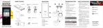
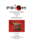
Mini4 Automatic Optical Switch Controller Board
(P/N 201810-xxx)
User’s Manual
And
Troubleshooting Guide
February 24, 2009
Rev A
Moog Components Group
Springfield Operations
750 West Sproul Road
Springfield, PA 19064
E-Mail: [email protected] URL: www.moog.com/components
Tel: 610-328-4000 Fax 610-605-6216
24/7 Technical Customer Support Hotline: 610-605-6101
Moog Components Group
201810-xxx Mini4 Automatic Optical Switch Controller
2/24/09
MANUAL REVISION HISTORY
REVISION
DATE
BY
NUMBER
REASON FOR
REVISION
Preliminary
8/2/07
GSG
ORIGINAL
A
2 /24/09
IB
Updated contact information to reflect
Moog Components Group
TABLE OF CONTENTS
MINI4 AUTOMATIC OPTICAL SWITCH CONTROLLER BOARD, P/N: 201810-XXX ........... 3
1
1.1
1.2
1.3
MINI4 AUTOMATIC OPTICAL SWITCH CONTROLLER BOARD REVISION HISTORY: .......................... 3
MINI4 AUTOMATIC OPTICAL SWITCH CONTROLLER BOARD DASH (-) NUMBER DEFINITIONS ........ 3
MINI4 AUTOMATIC OPTICAL SWITCH CONTROLLER BOARD OPERATION: ...................................... 4
1.3.1
1.3.2
1.3.3
1.3.4
1.3.5
1.3.6
Automatic Optical Switch Controller Board Indicators and Controls:.......... 4
Mini4 Automatic Optical Switch Controller Board Specifications: ............... 8
Mini4 Automatic Optical Switch Controller Board Dimensions:................... 8
Automatic Optical Switch Controller Board Power Requirements:............... 8
Power Section Testing..................................................................................... 8
Optical Section Testing ................................................................................... 9
1.4
STACK MINI4 SYSTEM INSTALLATION CHECKOUT PROCEDURE ...................................................... 9
1.4.1
1.4.2
Diagnostics Overview ..................................................................................... 9
Required Communications Hardware for Diagnostics................................. 10
Page 2 of 10
Moog Components Group
1
201810-xxx Mini4 Automatic Optical Switch Controller
2/24/09
Mini4 Automatic Optical Switch Controller Board, P/N: 201810-xxx
The Prizm Mini4 Automatic Optical Switch Controller Board is designed to monitor the
total optical signal power on two different fibers and to automatically control an externally
mounted DICON electrically-actuated optical switch module to select the best fiber. The
board monitors the receive optical power on both fibers and chooses the one with the highest
measured power. To minimize optical relay chattering, hysteresis is built into the
controller’s software. The board will only change from the primary fiber to the secondary
fiber (or vice versa) if the optical power difference is greater than 5dB. On power up of the
system, the primary fiber will be selected unless the board is in a manual mode.
This board requires an externally mounted single-pole-double-throw (SPDT) electrical
toggle switch. The switch is wired to the board using a pluggable 4-pin Phoenix plug and
attached to the board at J5. The toggle switch is an ON-OFF-ON 3-position switch without
a spring return to the center position. With the toggle switch in the center position, the
board is configured into the “Automatic” operational mode. With the toggle switch in either
of the two other positions, the board is commanded into a “Manual” mode and the DICON
optical switch will be forced to either the Primary (Optical Port 1) or Secondary (Optical
Port 2) optical selection. In “Manual” mode, the board will never change the selected
optical port unless the electrical toggle switch is changed.
The optical modules used on the board (pluggable small-form-factor (SFP)) are inherently
bi-directional and care must be taken to ensure the correct optical port (RX only) is
connected. The optical module’s receiver will monitor all of the 16 CWDM wavelengths
(1270 to 1610nm).
The Automatic Optical Switch Controller Board supports PMON II diagnostics through the
RS-485 diagnostics cable. Diagnostics will display the optical parameters from both of the
SFP modules and will also show the automatic optical switch activity (both optical receive
parameters and the control actions and LED statuses) on PMON II. Note: to acquire
diagnostics from the remote Automatic Optical Switch Controller Board, the board must be
either stacked on top of a Mini4 Video Input or Output board or have its 3-pin Phoenix
diagnostics cable connected to a Mini4 Video Input or Output board.
1.1 Mini4 Automatic Optical Switch Controller Board Revision
History:
The Mini4 Automatic Optical Switch Controller Board has gone through the following
printed circuit board (PCB) and Assembly revisions:
PCB Revision A/Assembly Revision A Original design..
1.2 Mini4 Automatic Optical Switch Controller Board Dash (-)
Number Definitions
The Mini4 Automatic Optical Switch Controller Board has a Dash Number appended to
the part number. This Dash Number identifies the specific board configurations:
Page 3 of 10
Moog Components Group
201810-xxx Mini4 Automatic Optical Switch Controller
2/24/09
-001 original configuration.
1.3 Mini4 Automatic Optical Switch Controller Board Operation:
The two SFP fiber modules are identified as link “A” or “B”. The location of the optical
receiver port (RX) is identified on the board next to each SFP module as either “RA” or
“RB”. “TA” and “TB” are also identified, but these ports are inactive for this board.
There is single green 2-pin Phoenix connector on the on the right side of the board for
supplying the board with +5VDC. Pin 1 (top of connector, labeled “+5V”) is the +5VDC
input and pin 2 (bottom of connector, labeled “GND”) is the ground.
There is single black 3-pin Phoenix connector on the on the right side of the board for RS485 diagnostics. Pin 1 (top of connector, labeled “RT+”) is the RT+ signal, pin 2 (center of
connector, labeled “GND”) is the ground/shield and pin 3 (bottom of connector, labeled
“RT-”) is the RT- signal. A Prizm Diagnostics cable can be connected directly to this 3-pin
connector or through a stacked Mini4 Video Input or Output board.
NOTE: The Automatic Optical Switch Controller Board is to be mounted only at the
surface location. The board can be stacked on top of a Mini4 Video Output board or
can be mounted separately.
On the left edge at the top of the board is green 4-pin Phoenix labeled “SELECTOR
SWITCH”, this is the connection point for the externally-mounted SPDT toggle switch.
Refer to the connector pin definitions in the following section.
On the left edge at the center of the board is green 4-pin Phoenix labeled “OPTICAL
SWITCH”, this is the connection point for the externally-mounted DICON electricallyactuated optical switch. Refer to the connector pin definitions in the following section.
On the left edge at the bottom of the board is green 6-pin Phoenix labeled “STATUS
LEDS”, this is the connection point for the three externally-mounted front panel status
LEDs. Refer to the connector pin definitions in the following section.
1.3.1
Automatic Optical Switch Controller Board Indicators and Controls:
LEDS:
There are 9 surface mount vertical LED indicators on the top of the board and 3 surface
mount right-angle LED indicators on the bottom of the board.
Top of Board
LED
Indication
D1 (Green)
Labeled “5V”, located at the top left of the board serves as an indicator that +5V DC is
available to the board. Supply voltage 5V to the board is selected via the placement of fuse F1
Page 4 of 10
Moog Components Group
201810-xxx Mini4 Automatic Optical Switch Controller
2/24/09
(or F2 or F3).
D2 (Green)
Located on the top center of the board, labeled ‘FIBR A’, provides an indication that the
transceiver module has detected the presence of an input signal on the fiber link. When ‘ON’
indicates that this board has a good level of received optical power on the fiber link A.
D3(Green)
Located on the top center of the board, labeled ‘FIBR B’, provides an indication that the
transceiver module has detected the presence of an input signal on the fiber link. When ‘ON’
indicates that this board has a good level of received optical power on the fiber link B.
D9(Green)
Located on the right center edge of the board, labeled ‘SEL A’, when ‘ON’ indicates that the
board is commanding the optical switch to select the A (or PORT 1) of the DICON switch.
D10(Green)
Located on the right center edge of the board, labeled ‘SEL B’, when ‘ON’ indicates that the
board is commanding the optical switch to select the B (or PORT 2) of the DICON switch.
D11(Green)
Located on the right center edge of the board, labeled ‘AUTO’, when ‘ON’ indicates that the
board is in the automatic optical switching mode.
D12(Green)
Located on the right center edge of the board, labeled ‘ERROR’, when ‘ON’ indicates that
the board has commanded the DICON switch to change the optical port but the DICON
switch electrical feedback indicates the wrong selection.
D13(Green)
Labeled “+3.3V PWR”, located at the bottom right of the board serves as an indicator that
+3.3V DC is operational on the board. 3.3V is generated by the on-board DC-DC converter
at U7.
D14(Green)
Labeled “LED PWR”, located at the bottom center of the board serves as an indicator that
+5V DC is being supplied to the LED header at J10. The +5V is supplied through fuse F4 on
the bottom of the board.
Bottom of Board
LED
Indication
D15 (Green)
Labeled “BLINK”, ‘ON’ with every other RS-485 access to the board. Used for testing.
D16 (Green)
Labeled “TX”, ‘ON’ when RS-485 diagnostics data is being sent out of the board on the RS485 diagnostics port.
D17 (Green)
Labeled “RX”, ‘ON’ when RS-485 diagnostics data is received into the board on the RS-485
diagnostics port.
FUSES:
There are four fuses for this board, all fuses are the self-resetting PTC type and will not
require replacement by the user.
F1:
2.6 Amp PTC, +5VDC input fuse at J8
F2:
2.6 Amp PTC, +5VDC input fuse for Diagnostics header at J4
F3:
2.6 Amp PTC, +5VDC input fuse for Daughterboard header at J3
Page 5 of 10
Moog Components Group
201810-xxx Mini4 Automatic Optical Switch Controller
2/24/09
– NOT PLACED
F4:
0.5 Amp PTC, +5VDC output fuse for LED header – NOT PLACED
SWITCHES:
There are no switches on this board. An externally-mounted SPDT toggle switch is
attached using connector J5.
CONNECTORS:
The fiber optic modules are identified as connectors,
J1:
Optics module “A”
J2:
Optics module “B”
There are two daughterboard stacking connectors.
Daughterboard Header
J3
VDC Supply
RXD_DB
GND
RXC_DB
RCV LINK
RXD_DB2
o
o
o
o
o
o
o
o
o
o
o
o
2
4
6
8
10
12
VDC Supply
TXD_DB
GND
TXC_DB
Future
TXD_DB2
o
o
o
o
o
o
o
o
o
o
2
4
6
8
10
RTGND
GND
+5V
+5V
Diagnostics Header
J4
RT+
GND
GND
+5V
+5V
J5:
1
3
5
7
9
“SELECTOR SWITCH” connector
(4-pin Phoenix Connector)
Selector Switch Connector
J5
o
o
o
o
1
3
5
7
9
11
1
2
3
4
J6:
SEL A
AUTO
SEL B
GND
RS-485 Diagnostics
(3-pin Phoenix Connector)
Page 6 of 10
Moog Components Group
201810-xxx Mini4 Automatic Optical Switch Controller
Diagnostics Connector
J6
o 1
o 2
o 3
RT+
GND
RT-
J7:
“OPTICAL SWITCH” connector
(4-pin Phoenix Connector)
Optical Switch Connector
J7
o
o
o
o
1
2
3
4
J8:
CTL 1
CTL 2
POS 3
POS 4
+5VDC power entry
(2-pin Phoenix Connector)
+5VDC Power Connector
J8
o 1
o 2
+5V
GND
J9:
“STATUS LED” connector
(6-pin Phoenix Connector)
Status LED Connector
J9
o
o
o
o
o
o
1
2
3
4
5
6
J10:
J10
LED A+
LED ALED B+
LED BLED AUTO+
LED AUTO-
16-pin ribbon, LED diagnostics
Led Status Connector
GND
FIBER_A
SEL_A
AUTO
ERROR
No connect
No connect
R_DIAG
1
3
5
7
9
11
13
15
o
o
o
o
o
o
o
o
o
o
o
o
o
o
o
o
2
4
6
8
10
12
14
16
PTC FUSE with +5VDC
FIBER_B
SEL_B
No connect
No connect
No connect
No connect
T_DIAG
NOTE 1: J10 header is located at the bottom center side of the board.
Pin 1 is the upper right pin – as identified by a square pad.
Page 7 of 10
2/24/09
Moog Components Group
201810-xxx Mini4 Automatic Optical Switch Controller
2/24/09
NOTE 2: Signals are active low.
JUMPER POSTS:
The board contains jumper posts to allow the user to configure each link for input or output
and for single-ended or differential signals. Other jumpers are used for factory
programming or testing and should not be move or changed.
Note: PIN 1 DENOTED BY SQUARE PCB PAD
JP1:
Cypress microprocessor programming header – do not use
JP2:
Laser enable/disable select for link A
2 o
|
1 o
2 o
to enable laser
to disable laser
1 o
Note: Laser should be DISABLED for normal operation.
JP3:
2 o
|
1 o
Laser enable/disable select for link B
2 o
to enable laser
to disable laser
1 o
Note: Laser should be DISABLED for normal operation.
1.3.2 Mini4 Automatic Optical Switch Controller Board Specifications:
Number of monitored optical links: 2 per board
Operational modes:
Manual (Select A or B) or Automatic
1.3.3 Mini4 Automatic Optical Switch Controller Board Dimensions:
Printed circuit board (PCB): 3.55 in x 3.775 in x 0.60 in board-to-board
(90.1mm x 95.88 mm x 15.24 mm)
1.3.4 Automatic Optical Switch Controller Board Power Requirements:
The Automatic Optical Switch Controller Board utilizes approximately 370mA @ 5VDC.
1.3.5
Power Section Testing
Page 8 of 10
Moog Components Group
201810-xxx Mini4 Automatic Optical Switch Controller
2/24/09
NOTE: The connectors on the bottom of the Automatic Optical Switch Controller Board
have pins that are connected to +5VDC and ground. If these pins are inadvertently
shorted together or to a common chassis ground, the board fuse (F1) will trip/reset.
If both the +5V Power LED and the +3.3V Power LED are out:
• Check for continuity of PTC fuse F1 with an ohmmeter.
• Replace PTC fuse if open.
If only the +5V Power LED is out:
• Verify +5V DC is present at the source
• At J8 if powered off of external power
• At J3 or J4 if powered off of the stacking connectors.
• If +5V is not available replace the board with a spare.
• If +5V is available check the display LED (D1).
If only the +3.3V Power LED is out:
• Verify +5VDC at F1 or J8 (replace board if +5VDC is not available)
• Verify +3.3VDC across C9 on top of board
• If +3.3V is not available replace the board with a spare.
• If +3.3V is available check the display LED (D13).
1.3.6
Optical Section Testing
############### ADD THIS SECTION ################
.
1.4 Stack Mini4 System Installation Checkout Procedure
NOTE: The Automatic Optical Switch Controller Board will work in a stand-alone
configuration without stacking the boards above a Mini4 Video Input or Output
board. This board is meant for operation at the surface location only.
For this PC/104 stack Mini4 System installation checkout procedure, it is assumed that the
Mini4 System is composed of one or more Video Input board(s) mounted in the vehicle and
one or more Video Output board(s) on the surface. +5VDC power for the Mini4 boards is
supplied by the user’s DC power supply powering the PC/104 stack and should be verified
to be between +4.75VDC and +5.25VDC at the 2-pin Phoenix power connector.
1.4.1 Diagnostics Overview
The Automatic Optical Switch Controller Board has been designed to include hardware and
firmware for monitoring various parameters of interest on the board. This capability is
accessed via a 3-pin Phoenix connector on the board that carries bi-directional RS-485
Page 9 of 10
Moog Components Group
201810-xxx Mini4 Automatic Optical Switch Controller
2/24/09
telemetry. The diagnostics will typically be used in conjunction with a user-supplied PC on
the surface, which has been loaded with PRIZM Modem Monitoring S/W (PMON II).
The Mini4 Video Input and Output board have a transparent link for carrying the
Diagnostics across the fiber link and does not require a user’s RS-485 channel. If the
Automatic Optical Switch Controller board is stacked on a Mini4 Video Input or Output
board diagnostics is automatically connected.
NOTE: The diagnostics feature in no way interferes with normal operation of the
modem – it is not necessary to be running the diagnostics software for any of the
Mini4 boards to work.
1.4.2 Required Communications Hardware for Diagnostics
The diagnostics capability is accessed via the 3-pin Phoenix connector on the Mini4 boards,
which provides the RS-485 connectivity to the on-board processor for diagnostics
communications. RS-485 was used because of its multi-drop capability, which in this case
allows all the Mini4 boards to be communicated with via a single channel. In this
configuration, no RS-485 multiplexer channel is needed.
The user is required to communicate with the Mini4 boards of the system via RS-485. A
typical installation is shown in the following drawing. This details a diagnostic connection
from a Windows PC running PMON II to a Min4 board stack.
Figure 1- Typical Cabling/Wiring for Back plane Diagnostics Telemetry
Page 10 of 10