1
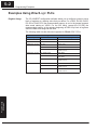
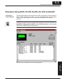
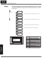
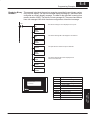
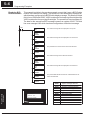
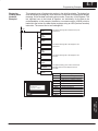
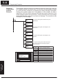
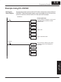
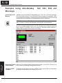
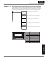
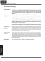
Programming
Examples
5
In This Chapter. . . .
— Examples Using DirectLOGIC PLCs
— Examples Using DL05, DL105, DL205, D3–350 and DL405
— Example Using D3–330/340
— Examples Using Allen-Bradleyt SLC 5/03, 5/04 and
Micrologix
— Troubleshooting
5–2
Programming Examples
Examples Using DirectLogic PLCs
Register Usage
The OP–WINEDIT configuration software allows you to configure a panel to use a
block of registers at a starting value that you define. For a DL05, DL105, DL205,
D3–350 or DL405 CPU the recommended memory to use is the general purpose
data words starting at V2000. For the 305 family (except the D3–350) the
recommended memory is the registers beginning at R400. Any block of registers
within the data word range can be used.
The following table lists the data word registers for DirectLOGIC CPUs.
System Setup
Data Word Registers for DirectLOGICt PLCs
Family
Configuring
Your Panel
Control Relay Registers
D0–05
V1200–V7377
DirectLOGICt DL105
F1–130
V2000–V2377
DirectLOGICt DL205
D2–230
V2000–V2377
D2–240
V2000–V3777
D2–250
V1400–V7377 and
V10000–V17777
D3–330/D3–330P
R400–R563
D3–340
D3
340
R400 R563 and
R400–R563
R700–R767
D3–350
V1400–V7377 and
V10000–V17777
D4–430
V1400–V7377
D4–440
D4
440
V1400–V7377
V1400
V7377 and
V10000–V17777
D4–450
V1400–V7377 and
V10000–V37777
DirectLOGICt DL305
Programming
Examples
CPU
DirectLOGICt DL05
DirectLOGICt DL405
5–3
Programming Examples
Examples Using DL05, DL105, DL205, D3–350 and DL405
Defining the
Status Register
The following examples assume that the OP–440 is configured for a base address of
V2000. When configuring the panel, use the configuration data and messages
shown in the following figure. Also, assume that message #140 consists of
all blanks.
Configuring Your
Operator Panel
NOTE: The Example Worksheet in Appendix A also has the configuration data and
messages needed for these examples. The example uses an F1–130 CPU, but
enter the PLC parameters for your PLC. The example shows how you can use the
worksheets to help plan your configurations.
Enter the above messages to run the example programs.
Programming
Examples
5–4
Programming Examples
Displaying
Messages
The following example shows two messages being displayed. The second line is
displaying message #4 and the bottom line is displaying message #8. The top and
third lines use data display message #140, which has been configured as a blank
text message.
C100
LD
K4
OUT
V2001
This selects message #4 to be displayed in the second line.
System Setup
LD
K8
OUT
V2003
This selects message #8 to be displayed in the bottom line.
Configuring
Your Panel
LD
V3000
OUT
V2006
This puts data from V3000 into the second line data field.
LD
K140
Select message #140 to blank the top and third lines.
OUT
V2000
OUT
V2002
Good Parts: 235
Programming
Examples
Process Step 1
V2000
V2001
V2002
V2003
V2004
V2005
V2006
V2007
V2010
V2011
V2012
V2013
Top line message selection
Second line message selection
Third line message selection
Bottom line message selection
Top line data
Top line data 2
Second line data
Second line data 2
Third line data
Third line data 2
Bottom line data
Bottom line data 2
5–5
Programming Examples
Displaying Binary
Numbers
This example is similar to the previous example, except that it uses a binary number
in the top line display. The top line uses data display message #1, which has been
configured as a binary display message. The data for the data field is coming from
memory location V2200. The third line is text message #8. The second and bottom
lines use message #140 which has been configured as a blank text message.
C101
LD
K1
This selects message #1 to be displayed in the top line.
OUT
V2000
This selects message #8 to be displayed in the third line.
OUT
V2002
LD
V2200
This puts data from V2200 into top line data field.
Configuring Your
Operator Panel
LD
K8
OUT
V2004
LD
K140
This selects message #140 to be displayed in the
second and bottom lines.
OUT
V2001
OUT
V2003
Parts Left: 12340
Process Step 1
Top line message selection
Second line message selection
Third line message selection
Bottom line message selection
Top line data
Top line data 2
Second line data
Second line data 2
Third line data
Third line data 2
Bottom line data
Bottom line data 2
Programming
Examples
V2000
V2001
V2002
V2003
V2004
V2005
V2006
V2007
V2010
V2011
V2012
V2013
5–6
Programming Examples
Displaying BCD
Double Numbers
This example is similar to the previous example, except that it uses a BCD Double
number in the bottom line display. The bottom line uses data display message #6,
which has been configured as a BCD Double display message. The data for the data
field is from V3002 and V3003. V3002 contains the four least significant digits while
V3003 contains the four most significant digits. The second line is text message #3.
The data for the second line BCD message comes from register V2100. The third
line uses message #140 which has been configured as a blank text message.
C102
LD
K8
This selects message #8 to be displayed in the top line.
System Setup
OUT
V2000
LD
K3
This selects message #3 to be displayed in the second line.
OUT
V2001
LD
V2100
This puts data from V2100 into the second line data field.
Configuring
Your Panel
OUT
V2006
LD
K140
This selects message #140 to blank the third line.
OUT
V2002
LD
K6
This selects message #6 to be displayed in the bottom line.
OUT
V2003
LDD
V3002
This puts the BCD Double number from V3002/V3003 into the
bottom line data field.
Programming
Examples
OUTD
V2012
Process Step 1
Tank Level: 1935
Count Val: 64197324
V2000
V2001
V2002
V2003
V2004
V2005
V2006
V2007
V2010
V2011
V2012
V2013
Top line message selection
Second line message selection
Third line message selection
Bottom line message selection
Top line data
Top line data 2
Second line data
Second line data 2
Third line data
Third line data 2
Bottom line data
Bottom line data 2
5–7
Programming Examples
Displaying
Floating Point
Numbers
Example 1
This example uses a floating point number in the third line display. The bottom line
uses data display message #7, which has been configured as a floating point display
message. Since the data is a floating point number, it uses two 16-bit registers. The
two registers have to be looked at together, not individually, for the data to be
understandable. In this example, the data is a constant number (168932) which is
loaded into the bottom line data display registers using an LDR (load real number)
instruction. The second line is text message #8.
C102
LD
K140
This selects message #140 to blank the top and
bottom lines.
OUT
V2003
LD
K8
This selects message #8 to be displayed in the
second line.
OUT
V2001
LD
K7
Configuring Your
Operator Panel
OUT
V2000
This selects message #7 to be displayed in the
third line.
OUT
V2002
LDR
R168932
OUTD
V2010
Process Step 1
Avg Part/Hr +1.68E+05
This puts the floating point number into third line
data field. Notice that the displayed value is
truncated.
V2000
V2001
V2002
V2003
V2004
V2005
V2006
V2007
V2010
V2011
V2012
V2013
Top line message selection
Second line message selection
Third line message selection
Bottom line message selection
Top line data
Top line data 2
Second line data
Second line data 2
Third line data
Third line data 2
Bottom line data
Bottom line data 2
Programming
Examples
5–8
Programming Examples
Displaying
Floating Point
Numbers
Example 2
System Setup
C102
This example is similar to the previous example, except that it gets its value from two
PLC registers instead of a constant value. The third line uses data display message
#7, which has been configured as a floating point display message. Remember,
floating point numbers require two 16-bit registers. In this example, the data is
loaded from V3010 and V3011 using an LDR (load real number) instruction to the
third line display registers V2010 and V2011. The top and bottom lines use message
#140 which has been configured as a blank text message. The second line uses
message #8, a text message.
LD
K140
This selects message #140 to blank the top and
bottom lines.
OUT
V2000
OUT
V2003
This selects message #8 to be displayed in the
second line.
LD
K8
OUT
V2001
Configuring
Your Panel
LD
K7
OUT
V2002
LDR
V3010
OUTD
V2010
Process Step 1
Avg Part/Hr +1.68E+05
Programming
Examples
This selects message #7 to be displayed in the
third line.
This puts the floating point number from V3010
and V3011 into the third line display registers
V2010 and V2011.
V2000
V2001
V2002
V2003
V2004
V2005
V2006
V2007
V2010
V2011
V2012
V2013
Top line message selection
Second line message selection
Third line message selection
Bottom line message selection
Top line data
Top line data 2
Second line data
Second line data 2
Third line data
Third line data 2
Bottom line data
Bottom line data 2
5–9
Programming Examples
Example Using D3–330/340
Defining the
Status Register
The following example assumes that the OP–440 is configured for a base address of
R400/R401. When configuring the panel, enter the messages shown in the previous
section for the DL05, DL105, DL205, D3–350 and DL405 examples.
DirectSOFT
Displaying Messages
IO0
DSTR F50
K1
This rung displays message #1 on the top line
and displays the top line data as a BCD
Double number.
DSTR F50
R500
DOUT F60
R410
Top line data.
Configuring Your
Operator Panel
DOUT F60
R400
DSTR F50
R502
DOUT F60
R412
First Scan
C374
DSTR F50
K2376
Top line data BCD Double.
This rung loads an arbitrary value (2376)
at memory locations to be displayed as
data values.
DOUT F60
R500
DSTR F50
K6759
DOUT F60
R502
Programming
Examples
5–10
Programming Examples
Examples Using Allen-Bradley
Micrologix
Interfacing to A-B
Memory
SLC 5/03, 5/04 and
OptiMate panels interface to Allen-Bradley SLC 5/03, SLC 5/04 and Micrologix
PLCs via integer file type N. The 5/03 and 5/04 have file type N7 as standard. Other
“N” type files can be created. The Micrologix has a fixed file type N7. Please see A-B
documentation for information on setting up and using “N” type files.
System Setup
NOTE: When using an OP–440 with an Allen-Bradley PLC, always be sure that at
least 12 words of memory are allocated to allow proper communications.
Configuring
Your Panel
All of the examples shown assume the OP–440 has been configured as shown
below (using OP–WINEDIT) with a file number N7 and base register address 0.
Assume that message #140 consists of all blanks.
BIN
BIN
BIN
BIN
BIN
Programming
Examples
BIN
BIN
Displaying Floating While the OP–440 can display floating point numbers, the A–B SLC PLCs do not
have a means of handling floating point numbers.
Point Numbers
Displaying BCD
Numbers
A–B deals with its registers in binary, not BCD. For this reason, during configuration
be sure to indicate Binary when setting up for A–B.
5–11
Programming Examples
Displaying Binary
Numbers
This example uses the configuration shown earlier, and shows two messages being
displayed. The top line uses data display message #1, which has been configured as
a binary display message. The data for the data field is a constant number 56432.
The data can also be moved to the data register from another register. The third line
is text message #8. Message #140 is selected for the second and bottom lines.
I:2
MOVE
Source
12
Dest
MOVE
Source
MOVE
Source
Dest
MOVE
Source
Dest
N7:0
140
8
56432
Process Step 1
Selects message #8 for the third display line.
N7:2
140
Selects message #140 for the bottom display line.
N7:3
Source 56432
Parts Left:
Selects message #140 for the second display line.
N7:1
MOVE
Dest
Selects message #1 for the top display line.
Configuring Your
Operator Panel
Dest
1
Puts binary data “56432” into the top line data field.
N7:4
N7:0
N7:1
N7:2
N7:3
N7:4
N7:5
N7:6
N7:7
N7:8
N7:9
N7:10
N7:11
Top line message selection
Second line message selection
Third line message selection
Bottom line message selection
Top line data
Top line data 2 (not used)
Second line data
Second line data 2 (not used)
Third line data
Third line data 2 (not used)
Bottom line data
Bottom line data 2 (not used)
Programming
Examples
5–12
Programming Examples
Troubleshooting
In this section, we explain how to isolate potential problems which may occur while
using the OP–440. Because these panels have only a power supply connection and
a communications connection, no DIP switches or controls to set, and cannot be
used in multiple panel arrangements, troubleshooting is a very straightforward
operation.
Power
Supply Problems
If the panel LED display and the RX and TX LEDs on the back of the panel do not
illuminate, the panel is most likely not receiving input power. Carefully check your
connections to make sure they are tight. If this does not help, see Chapter 2 and
review the input power requirements.
Remember, all PLC’s require that you use the OP–PS400 5V plug-in power supply
(or equivalent) for configuration. Some PLC’s also require that you use this power
supply for operation. Make sure that the 120 VAC receptacle you plug the power
supply into has power. Also, if you are using another 5V power supply, make sure
that it has a center negative connector.
If using a PLC that supplies 5V for operation through the communications cable,
check to make sure sure that pin 5 on the lead going into the panel has a 5V signal.
Configuration
Problems
Make sure that you are using the proper configuration cable (OP–CCBL) and that it
is securely connected. Check your configuration program and make sure the proper
communications port is selected, such as COM1 or COM2. Review your
configuration settings to make sure they are correct. Remember, the OP–WINEDIT
Help screens provide a lot of valuable information.
Communication
Problems
Observe the RX and TX LEDs on the rear panel. They should be steady flashing or
glow (depending on the baud rate). If not, make sure that you are using the proper
communications cable and that it is securely connected. Review your configuratiion
settings and make sure that the communications information for your PLC, address
number, baud rate, protocol type, etc. is correct. Check the user manual for your PLC
for the proper settings.
Getting Help
See “Technical Support” in Chapter 1 for additional information.
Programming
Examples
Configuring
Your Panel
System Setup
Troubleshooting