1
Table of Contents
Preface .......................................................................................................................................... 4
Important notice ............................................................................................................................. 5
1. Introduction ............................................................................................................................... 6
1.1. Characteristics ................................................................................................................. 6
1.2. Specifications .................................................................................................................. 7
1.3. Minimum system requirements ........................................................................................... 7
2. Equipment interface .................................................................................................................... 8
2.1. Front view ...................................................................................................................... 8
2.2. Side view ....................................................................................................................... 8
3. Installation ................................................................................................................................. 9
3.1. Connection of the device .................................................................................................. 9
4. Initial configuration ................................................................................................................... 10
5. Control and configuration ......................................................................................................... 12
5.1. Outlets ......................................................................................................................... 12
5.1.1. Manual outlet control .......................................................................................... 12
5.1.2. General outlet settings ......................................................................................... 13
5.1.3. Watchdog ......................................................................................................... 14
5.1.4. Timer ................................................................................................................ 15
5.2. Device configuration ...................................................................................................... 16
5.2.1. Time settings ...................................................................................................... 16
5.2.2. E-mail configuration ............................................................................................ 17
5.2.3. Network settings ................................................................................................. 18
5.2.4. User account management ................................................................................... 19
5.2.5. Firmware upgrade .............................................................................................. 21
5.2.6. System settings ................................................................................................... 23
5.3. Control of the device via Telnet or CGI ............................................................................ 24
5.3.1. Encrypted login .................................................................................................. 24
5.3.2. Communication via KSHELL interface ..................................................................... 24
5.3.3. CGI control ........................................................................................................ 25
5.3.4. Using kshell.cgi interface to control the device ........................................................ 26
5.3.5. List of telnet and kshell.cgi commands ................................................................... 26
5.3.6. Return values ..................................................................................................... 33
5.4. Manual control ............................................................................................................. 34
5.5. Status LED diodes .......................................................................................................... 34
5.6. Troubleshooting ............................................................................................................. 35
5.6.1. Forgotten password. Reset to factory settings .......................................................... 35
5.6.2. Problem with update of firmware .......................................................................... 35
5.6.3. Changing the fuse .............................................................................................. 35
Conclusion ................................................................................................................................... 36
2
List of Figures
1. Front view .................................................................................................................................
2. Side view ..................................................................................................................................
3. Devices found ..........................................................................................................................
4. Configuration of the device .......................................................................................................
5. Login screen ............................................................................................................................
6. Manual outlet control ................................................................................................................
7. General outlet settings ..............................................................................................................
8. Watchdog settings ....................................................................................................................
9. Timer settings ...........................................................................................................................
10. Date and time configuration ....................................................................................................
11. E-mail configuration ...............................................................................................................
12. Network configuration ............................................................................................................
13. Add user ...............................................................................................................................
14. Detailed user permissions management .....................................................................................
15. Select file and upgrade screen .................................................................................................
16. NETIO restarts after finished upgrade .......................................................................................
17. System settings .......................................................................................................................
8
8
10
10
11
12
13
14
15
16
17
18
19
20
21
22
23
3
Preface
Thank you for purchasing a KOUKAAM product. To prevent incorrect installation or improper use of equipment
please carefully read these Operating Instructions and the Quick Installation Guide, which is included in the
package.
Carefully read the following notice. The device you have purchased operates under a certain voltage. Incorrect
manipulation with the device may result in damage to the device or injury to the person handling it.
4
Important notice
1. The manufacturer is not liable for potential damage caused by incorrect usage or placing the device in an
unsuitable environment.
2. The device is not intended for usage outdoors.
3. Do not use the device in an environment with strong vibrations.
4. Unauthorised modification of this device can damage it or cause fire.
5. Prevent contact with fluids; do not expose the device to high temperatures.
6. Protect the device from falling.
7. Only devices approved for use in the electricity network may be connected.
8. If the device malfunctions, disconnect it from the electric power supply and contact your vendor.
5
1. Introduction
The NETIO-230B is a multifunctional power supply controller. This device is intended to control power supply via
web interface, telnet, or CGI commands. Thanks to the network administration technology based on IP protocol
basis, the user can control or provide a power supply to a connected external device (appliance) via a computer
connected to the LAN or Internet network. No special software is necessary to control the device, the Web interface
is already integrated in the firmware. Using the web interface, you can easily control and set the entire device
and individual outputs.
Imagine that you are travelling around the world and you can remotely or via a timer control the power supply
to your electrical appliances, such as, computers, servers, routers, electric gates, security/surveillance system or
other appliances.
1.1. Characteristics
• Integrated web server
• Support for a broad spectrum of browsers:
• Internet Explorer
• Mozilla Firefox
• Opera
• Google Chrome
• Four controllable ports
• Four manual control buttons
• Support for HTTP, SMTP, SNTP, DHCP, DNS, Telnet protocols
• Control using CGI commands
• Possibility to login using an encrypted password
• User authorisation
• LED indication of the actual state of each port
• Safe anti-electric shock design, fire-resistant materials
• Time control - you can set the on/off time for the requested port
• Default setting of port state after switch-on and restart of the device
• Watchdog function for reseting frozen network device
• E-mail notification
• Over-voltage protection on the entire device and all the four outputs
6
Introduction
1.2. Specifications
Power supply voltage:
230 V AC
Maximum switched current:
10 A
Dimensions:
300 × 60 × 90 mm (h × w × d)
Network interface:
1x RJ-45 10/100 Mbit/s
1.3. Minimum system requirements
• Computer with Internet browser (Microsoft Internet Explorer, Opera, Mozilla Firefox, …) with JavaScript support
enabled.
7
2. Equipment interface
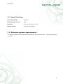
2.1. Front view
Figure 1. Front view
1. Controlled power supply outputs 230V
2. Four indicator LED diodes
3. Manual buttons for switching outputs on/off
4. Power supply cable 230V
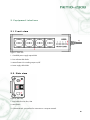
2.2. Side view
Figure 2. Side view
1. Fuse holder for main fuse, 10A
2. Main Switch
3. Connector RJ-45 - an interface for connection to a computer network.
8
3. Installation
Before using the device for the first time, check whether the power supply voltage setting is 230 V AC.
3.1. Connection of the device
1. Connect the NETIO-230B to the computer network (switches, router) using the network cable with RJ-45
connectors.
2. Connect the NETIO power supply cable to the socket.
3. Connect the device, which you want to control, to the appropriate output.
4. Switch on the NETIO-230B using the switch on the side of the device.
9
4. Initial configuration
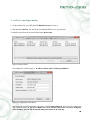
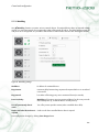
1. On the enclosed CD, you will find the file NetioDiscover.exe, execute it.
2. Click the button Discover. This lists all the accessible NETIO devices in your network.
3. Select the device from the list and click the button Device setup.
Figure 3. Devices found
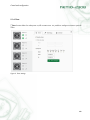
The configuration window appears - IP address, Subnet mask and Gateway IP Address.
Figure 4. Configuration of the device
After editing the network configuration parameters, click the button Change IP, which saves the configuration
and restarts the device. If you have a DHCP server in the network and you do not want to change the
network settings, you can skip the manual setting and continue to the next step.
10
Initial configuration
The default IP address of the device is 192.168.10.100 if you do not have a DHCP server in the network. If
you have, the device obtains an IP address automatically from the DHCP server.
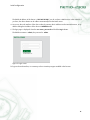
4. You access the web interface of the device either by entering the IP address into the Internet browser, or by
double-clicking the IP address of the device in NETIO discover.
5. The login page is displayed. Enter the user name, password and click the Log in button.
The default username is: admin, the password is: admin.
Figure 5. Login screen
To login to the web interface, it is necessary to have JavaScript support enabled in the browser.
11
5. Control and configuration
5.1. Outlets
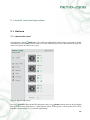
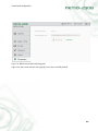
5.1.1. Manual outlet control
In the left menu, choose
Outlets item. You will be provided with the outlet overview. Each outlet is directly
controlled by four associated icons. All outlets at once are controlled by two icons at the bottom of the page. The
active icon is green, the inactive icon is grey.
Figure 6. Manual outlet control
Use icon
On/Off for direct control of outlet power supply. Icon
Restart performs restart of device plugged
into the outlet. During restart, there is a delay between power off and power on of the outlet, which can be
adjusted in section Section 5.1.2, “General outlet settings”.
12
Control and configuration
All outlets can be controlled at once by means of two icons at the page bottom. Depending on current outlet state,
it is possible either to power off or power on all outlets and also to restart them.
5.1.2. General outlet settings
Use panel
General settings to configure various outlet related settings. Outlet name serves for outlet
identification and is displayed above its control icons. Reset delay is a number of seconds to wait between power
off and power on during outlet restart cycle. Check last option to power on the outlet by default after NETIO
starts up such as after power outage.
Figure 7. General outlet settings
Save configuration changes by clicking Save changes button.
13
Control and configuration
5.1.3. Watchdog
Use
Watchdog function to monitor various network devices. If monitored device does not respond to Ping
request in a given time interval, the corresponding outlet will be turned off and on. The delay between power off
and power on is configurable. It is possible to limit number of outlet restarts so that it does not happen infinitely.
Figure 8. Watchdog settings
IP address:
IP address of monitored device.
Ping timeout:
maximum delay between Ping request and response before it is considered
unsuccessful.
Ping interval:
how often will be Ping query sent to monitored device (in seconds).
Power-on delay:
Watchdog will postpone querying monitored device for this many seconds
after outlet power up, so that the device can fully start up.
Turn-off permanently after X
resets.
Turn off to prevent periodic restarts (when controlled device fails).
Send e-mail when device doesn't
respond.
Sends e-mail when controlled device doesn't respond.
Save configuration changes by clicking Save changes button.
14
Control and configuration
5.1.4. Timer
Timer function allows for outlet power on/off at certain times. It is possible to configure one-time or periodic
action.
Figure 9. Timer settings
15
Control and configuration
5.2. Device configuration
Please pay attention to device configuration, so that it can function properly.
5.2.1. Time settings
Click
Date and time in the left menu. The device supports three ways of time configuration. Time can be set
manually or synchronization with a NTP server or client's computer can be used. Daylight saving time option
is also available.
Figure 10. Date and time configuration
Save date and time settings by clicking Save changes button.
16
Control and configuration
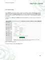
5.2.2. E-mail configuration
Click
E-mail from left menu. The setting will be used to send e-mail reports from this device.
Figure 11. E-mail configuration
SMTP server:
mailserver used to send message.
Enable SMTP authentication:
check this option, if mail server requires authentication.
Note: NETIO-230B does not support STARTTLS encryption.
To:
message recipient address.
From:
address, that will appear as message sender.
Subject:
message subject.
Save e-mail settings by clicking Save changes button. It is possible to verify configuration by clicking Send test
e-mail button.
17
Control and configuration
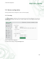
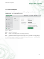
5.2.3. Network settings
Click
Network in the left menu. If there is a DHCP server available, the device will automatically configure
various network related parameters, such as IP address, network mask and gateway. Check Use DHCP option to
enable this behavior. Use Set static IP address option to manually configure these parameters. Static IP address
is also required for successful firmware upgrade. Please read Section 5.2.5, “Firmware upgrade” chapter for
further details.
Configuration items Web port and KSHELL port sets Web and KSHELL ports. Default settings are sufficient for
most users.
Figure 12. Network configuration
Save network settings by clicking Save changes button.
18
Control and configuration
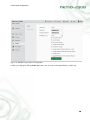
5.2.4. User account management
If the device is used by multiple users, using accounts with different privileges is advised. In the left menu, click
Users menu item. There are three different user types:
Figure 13. Add user
Admin:
user with full authorisation
User:
user that can control the ports, but cannot change system settings
Guest:
user that does not have the rights to change any settings and can only see the current state of the ports
Pick one of above options as necessary. There is option of finer grained access control. List of all available
permissions will be available after clicking More hyperlink:
19
Control and configuration
Figure 14. Detailed user permissions management
Confirm your settings by clicking Create user button. User accounts can be adjusted later in similar way.
20
Control and configuration
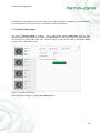
5.2.5. Firmware upgrade
In section
Firmware, firmware of your device can be upgraded. New versions are available at http://
www.koukaam.se/showproduct.php?article_id=1479.
Warning: use Chrome browser and static IP address configuration, otherwise the upgrade process may fail.
Select file with new firmware (.bin extension) and continue by clicking Upgrade button.
Figure 15. Select file and upgrade screen
NETIO will restart several times during upgrade. Do not turn it off, otherwise there is threat of permanent failure.
You will be continuously notified about upgrade progress until it is finished.
21
Control and configuration
Figure 16. NETIO restarts after finished upgrade
Login screen after restart indicates, that upgrade process has successfully finished.
22
Control and configuration
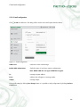
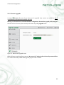
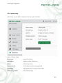
5.2.6. System settings
In this section, you can do basic settings and view basic system parameters.
Figure 17. System settings
Device name:
Name of your device.
MAC address:
Hardware address of this device.
Uptime:
Time from last restart.
Firmware version:
Current firmware version and upgrade link.
Switch delay:
Delay between turn on of two and more outlets.
Restore factory defaults
Reload default settings.
23
Control and configuration
5.3. Control of the device via Telnet or CGI
5.3.1. Encrypted login
For login with secure password, you must first get the hash code from the device. You get this either in the return
code after connection via KSHELL or the CGI command hash. For calculation, the MD5 sum is used that has been
calculated as the following sum <name><password><hash>. This is a 128b number (32 characters) transmitted
in a hexadecimal format.
5.3.2. Communication via KSHELL interface
The connection procedure is shown in the following example:
1. Open the window with command line
2. Enter the command telnet 192.168.10.100 1234 (enter the address after the address of your device, will
1234 with the port, which you have set for KSHELL on the device)
3. The device should list a response similar to the following: 100 HELLO EB5D61F6. The last 8 characters comprise
the hash string used for encrypted login.
4. Now you can login with the command:
login name password
where name is the username and password is your password. If you have entered the correct username and
password, the device response is 250 OK. You are now logged on and you can control the NETIO device using
the commands from the following chapter.
Every communication session via KSHELL interface has limited validity. In case of inactivity of approximate
duration one minute, the session will be terminated automatically. If you need to keep the session active, you
can use the command noop.
24
Control and configuration
5.3.3. CGI control
The NETIO-230B device can be also easily integrated into your applications using CGI commands.
CGI control of the device is executed by commands in the following format:
http://<IP address>/cgi/control.cgi?<command>&<command>
Replace the string <IP address> with the IP address of your device. The string <command> is the actual command.
CGI commands:
hash=hash
Sends a request for an encrypted login string. The command returns <html> hash </html>.
login=<p|c>:<user name>:<password>
Login to the device. Use command login=plain for unencrypted login. For encrypted login, use
command login=crypted. Other command parameters are username and password.
The return values are described in chapter Section 5.3.6, “Return values”. In case of using CGI
commands, the return value is enclosed in the HTML tags <html> a </html>.
quit=quit
Logout from the system. The return value is <html>110 BYE</html>. This command can be
used only in CGI compatible mode.
port=<list|xxxx>
The parameter list - lists the output state in the format <html> port1 port2 port3 port4 </html>,
where port1 to port4 are values 0 for output off and 1 for output on. The parameter xxxx is
a string for setting the port. Replace symbol x with 0, 1, u or i just as applies to port setting
via Telnet.
All commands can be shortened to individual symbols. For example, the command port=list can shortened to
p=l. The commands can be joined in a string using the symbol &.
Example:
http://192.168.200.84/cgi/control.cgi?login=p:admin:admin&p=10ui
This command executes login to the device at the address 192.168.200.84 with username admin, password
admin and sets the output. It switches on output 1, switches off output 2, leaves output 3 in its current state and
interrupts output 4 for the time set in the actual setting of the output.
25
Control and configuration
5.3.4. Using kshell.cgi interface to control the device
NETIO 4.0 has a new control interface. It contains both the original control.tgi (now control.cgi) and the new
kshell.cgi kshell.cgi script.
Use it as follows:
http://192.168.1.10/cgi/kshell.cgi?session=ssid {session_id}&cmd={kshell_command}
Session_id is a hexadecimal number returned during the initialization of communication. Kshell_command is one
of commands described in the table below.
Initialize
http://192.168.1.10/cgi/kshell.cgi?session=init {salt}
Use while communicating
http://192.168.1.10/cgi/kshell.cgi?session=ssid
72b4c5f313c2133df8da6581ec41b393&cmd=kshell_command
Close
http://192.168.1.10/cgi/kshell.cgi?session=close
72b4c5f313c2133df8da6581ec41b393
5.3.5. List of telnet and kshell.cgi commands
Basic commands
login <name> <password>
Sign in using the plain password. Example: Use command login admin admin to log in with
username admin a password admin.
login <name> <md5>
Sign in using the encrytped password.
version
Gets firware version.
alias
Gets the device name.
alias <name>
Set the device name.
quit
Sign out. In case of changes in system settings, perform restart of the device.
reboot
Sign out, closes the connetion and restarts the device.
26
Control and configuration
noop
Keeps the connection alive, performs no action.
uptime
Gets the current uptime.
Commands for system settings.
system time <YYYY/MM/DD,HH:MM:SS>
Sets the local time.
system time
Gets the local time in the formar YYYY/MM/DD,HH:MM:SS.
system dst <mode> <dst_start> <dst_end>
Sets the daylight saving settings.
system dst
Gets the daylight saving settings in the formar <mode> <dst_start> <dst_end>
system webport <port>
Sets the web port of the device. The default value is 80.
system webport
Gets the web port of the device.
system kshport <port>
Sets the kshell port of the device.
system kshport
Gets the kshell port of the device. The default value is 1234.
system dhcp
Gets the DHCP client parameter setting.
system dhcp hostname <enable|disable>
Enables sending the name of the DHCP server.
system dhcp sntp <enable|disable>
Enables setting the SNTP server according to the IP address set on the DHCP server.
system reset
27
Control and configuration
Restores the device to factory defaults. After posting this command, factory defaults is restored
and system restarts.
system timezone <+|-offset>
Sets local timezone. Enter the time offset in minutes.
system timezone
Gets time offset of the local time from UTC. The return value is in minutes.
system sntp
Gets SNTP client settings.
system sntp <enable|disable> <sntp_ip|domain>
Sets SNTP client. Enables or disables time synchronization with the SNTP server. The server
address can be entered as an IP address or as a domain name.
system dns <ip>
Sets the IP address of the DNS server. You have to restart the system using the command reboot
or turn off and on your Netio for the changes to take effect.
system dns
Gets the set address of the DNS server.
system swdelay <delay>
Sets the delay between turning on of two outputs. Enter the value in tenths of seconds.
system swdelay
Gets the delay between turning on of two outputs.
system discover <enable|disable>
Enables/disables network parameter settings from the discover utility.
system discover
Gets whether the system discover selection is enabled or disabled.
system eth
Gets the network interface settings in the format: <dhcp | manual> <ip_address> <mask>
<gateway>
system eth <dhcp | manual> [<ip_address> <mask> <gateway>]
Sets the network interface - IP address, network mask and gateway are set only if the manual
parameter is selected. For the changes to take effect, it is necessary to either restart the system
with the command reboot, or switch the NETIO off/on.
28
Control and configuration
Example: The system command eth manual 192.168.10.150 255.255.255.0 192.168.10.1
sets the network address 192.168.10.150, network mask 255.255.255.0 and default gateway
to 192.168.10.1.
system network
Gets network settings in the format: <webport> <kshport> <dhcpntp> <mode> <IP> <mask>
<gateway> <DNS>
system network <webport> <kshport> <dhcpntp> <mode> <IP> <mask> <gateway> <DNS>
Network settings.
system update
Switch to the upgrade firmware mode.
system mac
Gets MAC address of the device.
system reboot
Reboots the device.
Port commands
port list [xxxx]
• without parameter gets the state of all ports
• xxxx is a command for control of all ports simultaneously - in place of x enter the commands:
• 0 - deactivate output
• 1 - activate output
• i - call interruption of a given output
• u - leave output unchanged
Example: The command port list 01ui deactivates output 1, activates output 2, leaves output 3
unchanged and interrupts output 4.
port elist
Gets port settings in the format: <name> <state> <wd> <wd_ip> <mode> <wd_int> <wd_to>
<timer_mode> <on_time> <off_time> <ws>.
port setup <output> [ <output_name> <mod: manual|timer> <interrupt_delay> <PON_status> ]
Command for setting output parameters - the meaning of the parameters is as follows:
<output_name> - Entered in quotation marks (it is possible to omit the quotation marks if it does
not contain whitespaces)
29
Control and configuration
<mod: manual|timer> - Selection of output mode.
<PON status> - State after turning the device on: 0 - off / 1 on
Example: The command port setup 1 "output 1" manual 2 1 sets output 1 name of output 1,
activates manual control, sets the interruption time to 2 seconds and sets the status upon turning
on to on.
port timer <output> <time_format> [ <mode: once | daily | weekly> <on-time> <off-time>] <week_schedule>
Timer settings:
<output> - the number of the output that is being set
<time_format> - set time format
t:
HH:MM:SS
dt:
YYYY/MM/DD,HH:MM:SS
ux:
xxxxxxxx (unsigned long with prefix
0x<hex>, 0<octal> or decimal)
<mode once | daily | weekly> - Selection of timer mode.
<on-time> - time when the output will be turned on.
<off-time> - time when the output will be turned off.
<week schedule> - a series of ones and zeros; the first number represents Monday, the last
represents Sunday.
Example: The command port timer 3 t weekly 08:00:00 17:30:00 1111100 switches the timer
on at output 3. From Monday to Friday, output 3 will always be switched on at 08:00 and
switched off at 17:30.
port timer <output> <d | t | u>
Gets the timer settings in the given format for the selected port.
port wd <output>
Gets Watchdogsettings of given outlet in the following format:
<wd: enable | disable> <wd_ip_addr> <wd_timeout> <wd_PON_delay>
<ping_refresh> <max_retry> <max_retry_poff: enable|disable> <send
email: enable|disable>
port wd <output> <wd: enable|disable>
Enables or disables Watchdog function.
Example: The command port wd 4 enable activates the Watchdog function on output 4
port wd <output> <wd: enable | disable> <wd_ip_addr> <wd_timeout> <wd_PON_delay> <ping_interval>
<max_retry> <max_retry_poff: enable|disable> <send_email: enable|disable>
30
Control and configuration
Watchdog settings command. The meaning of the parameters is as follows:
<output> - number of the output you are setting
<wd: enable | disable> - enable/disable Watchdog function on the given
output
<wd_ip_addr> - IP address of the monitored device
<wd_timeout> - maximum ping timenout of the monitored device, before it
is restarted
<wd_PON_delay> - time interval (in seconds) in which the Watchdog function
will not be active after output restart. During this period, the monitored device
should start operating after restart.
<ping_interval> - interval (in seconds) in which queries will be sent to the
device
<max_retry> - maximum number of output restart attempts if the monitored
device does not respond to the ping commands. After expiry of the given
number of attempts, the output remains inactive.
<max_retry_poff: enable|disable> - enable/disable max_retry function
<send_email: enable|disable> - enable/disable e-mail report when the
monitored device is unavailable or the value of max_retry is exceeded.
Example: The command port wd 2 enable 192.168.10.101 10 30 1 3 enable enable enables
the Watchdog function on output 2. The device at the address 192.168.10.101 will be
monitored. The maximum response time of the monitored device will be 10 seconds. The ping
commands will be sent at one-second intervals. If the monitored device does not respond within
10 seconds, output 2 is switched off for 30 seconds. If the device will not respond to ping
commands after set switch-off three times in a row, the output is switched off for the fourth
time and remains off. A warning e-mail message will be sent to you each time the output is
switched off.
port mode <port_num> [<mode>]
• bez parametru <mode> vypíše aktuální režim portu,
• s parametrem nastaví režim portu.
port <output> [0 | 1 | manual | int]
Gets and sets output state:
• if you enter only the number of the output without any parameter, the command gets the
output state (0 - off / 1 - on)
• output number with parameter 0/1 - turns the output on/off
• output number with parameter 'manual' - switches output to 'manual' control
• output number with parameter 'int' - interrupts the output
31
Control and configuration
Example: The command port 2 1 activates output 2.
E-mail commands
email server
Gets the IP address or domain name of the SMTP server.
email server <ip | domain_server_address>
Sets the IP address or domain name of the SMTP server.
email message
Gets e-mail settings.
email message <sender> <receiver> <subject>
Sets e-mail settings.
email auth
Gets settings of the SMTP authentication.
email auth <enabled> <method> <username> <password>
Sets settings of the SMTP authentication.
User and privileges commands
user get
Gets user privileges of the currently signed user in the format: <id> <name> <privileges>.
id
user number, 0 - 5
name
username
privileges
Gets a list of user privileges in the format OCVMSNAUF,
the meaning of the parameters is as follows:
• O: view outlet status
• C: control outlets
• V: view outlet settings
• M: change outlet settings (timer, watchdog)
• S: view NETIO settings (time, e-mail, network)
• N: change simple settings (time, e-mail)
• A: change advanced settings (network)
• U: manage users
32
Control and configuration
• F: upgrade firmware, reset to factory defaults
user add <name> <privileges> <GUI> <passwd>
Adds new user.
GUI
Information for GUI, enter 0 if used via kshell
passwd
password
user list
Gets a list of users in the format <id> <name> <privileges> <GUI>.
user delete <id>
Deletes user.
user passwd <id> <old> <new>
Changes user password.
user update <id> <name> <privileges> <GUI> <passwd>
Updates user settings.
5.3.6. Return values
100 HELLO <hash>
Device response after connection. Hash after HELLO can be used for encrypted login.
110 BYE
You have been signed out.
120 Rebooting....
Restarting.
130 CONNECTION TIMEOUT
Connection time-out.
250 OK
Command was successfully executed. The value returned by the called command may follow.
500 INVALID VALUE
Incorrectly entered value.
501 INVALID PARAMETR
Incorrectly entered parameter.
33
Control and configuration
502 UNKNOWN COMMAND
Incorrectly entered or unknown command.
503 INVALID LOGIN
Incorrectly entered username or password.
504 ALREADY LOGGED IN
You are already signed in.
505 FORBIDDEN
You are not authorised to execute the given command. Sign in as user with higher privileges.
506 INPUT LINE TOO LONG
You have sent an input line that is too long. Shorten the command and repeat the action.
507 TOO MANY CONNECTIONS
Maximum number of connections was exceeded. Wait for someone to sign out. If inactive users
are signed in, they will be disconnected automatically upon expiry of the time limit.
5.4. Manual control
Apart from control via PC, the device can also be controlled using the four buttons on the front panel. To switch
the given output on or off, press the button for two seconds. If the output was off, it comes on, if it was on, it goes
off. The buttons correspond to the outputs 1-4, from left to right. The state of the individual ports is signaled by
the green diode above the button for the given port that either switches on or off.
5.5. Status LED diodes
The status LED diodes on the device inform the user not only about the status of the output, but also provide him
with some information about the status of the system.
The green LED diodes provide information about the actual status of the output. If diodes 1-4 are green, the
individual outputs are on. If any of the concerned diodes is not green, this specific output is off.
The red LED diodes inform the user about different statuses of the entire device. The following states are possible:
Red LED 1 is on:
initialisation of network interface; if it remains on, the network is not available.
Red LED 2 is on:
posting of query to DHCP
Red LED 3 is blinking:
firmware update in progress
Red LED 4 is on:
device is in firmware update mode
34
Control and configuration
5.6. Troubleshooting
5.6.1. Forgotten password. Reset to factory settings
If you forget your password, it is possible to reset to factory mode. This is done by pressing and holding buttons 1
and 2 with device on. Hold the buttons until the device beeps 2x. During the resetting process, all the LED diodes
are red. As soon as reset is completed, the LED diodes go off.
5.6.2. Problem with update of firmware
If a problem arises during updating the firmware (e.g. power failures, or switching off the device before the
update is completed), it is possible to force putting the device into operation in firmware update mode. You do
this by pressing button 4 with device on. Hold the button until the device beeps. After this, connect to the device IP
address via the browser. Continue to enter the firmware file as shown in the chapter which describes the firmware
update process.
5.6.3. Changing the fuse
If the NETIO-230B stops working and no indication LEDs are not shining, it is possible that the fuse has been
blown. Before actual replacement of the fuse, make sure that the NETIO-230B IS OFF and DISCONNECTED FROM
THE POWER SUPPLY. Disconnect also all devices connected to the outputs. To replace the fuse, unscrew the fuse
holder (ideally using a flat screwdriver). Always replace the fuse with a new fuse of same type (250V 10A, type
F). After insertion of the correct fuse, replace the plastic holder and screw it into place. Connect the power supply
cable and try to switch on the device. Before reconnecting all the devices to the outputs, check whether the fuse
was not blown by a fault on the connected devices.
35
Conclusion
The manufacturer bears no responsibility for any technical or printing errors and reserves the right to make any
changes in the product and in this user manual without prior notice. Any such changes will be announced via
the manufacturer's website www.koukaam.se.
The manufacturer does not provide warranties of any kind whatsoever with regard to any information given in
this user manual or any derived warranties regarding product saleability or fitness for a specific purpose.
In particular, the manufacturer does not provide any warranties for defects caused by incorrect use of the product,
failure to abide by the instructions and recommendations stated in the user manual and for any defects caused
by unprofessional activities of third parties outside the manufacturer's authorized service shop.
We believe that you will be satisfied with our product. In case of any questions or comments relating to the
functionality of the NETIO product, please do not hesitate to contact us.
The company KOUKAAM a.s. represents that all products, software and other third party components used in this
equipment were used by the company KOUKAAM a.s. on the basis of the relevant consent and pursuant to licence
agreements between the company KOUKAAM a.s. and third parties. The company KOUKAAM a.s. reserves the
right to change those licence terms and conditions, as the case may be, and such changes will be published in
the updated version of a manual available on the website of the company KOUKAAM a.s. - www.koukaam.se
The KOUKAAM Team
KOUKAAM a.s.
Kaplanova 2252/8
Prague 4, 148 00
Czech Republic
www.koukaam.se
© 2012 KOUKAAM a.s. All rights reserved.
36