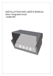
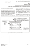
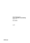
1
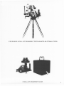
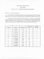
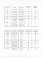
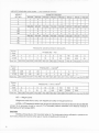
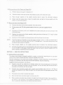
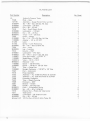
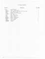
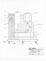
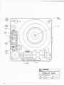
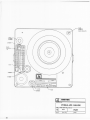
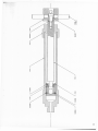
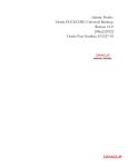
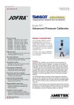
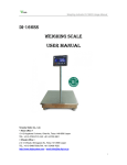
HANDBOOK
OPERATING AND SERVICE
INSTRUCTIONS
MANSFIELD & GREEN
PRESSURE TESTER
HYDRA–LITE TM DEADWEIGHT INSTRUMENTS
MODEL HL DEADWEIGHT TESTERS
MODEL HLG DEADWEIGHT GAUGES
FOR REPAIR AND RECALIBRATION
RETURN TO
8600 SOMERSET DR., LARGO, FL 33773
FORM NO. 73-17 (Rev 7)
10/97 ER 97-119
\METEK
TEST AND CALIBRATION INSTRUMENT DIVISION
Testing Equipment
INSTRUCTION
BULLETIN
HYDRA-LITE DEADWEIGHT TESTERS
AND DEADWEIGHT GAUGES
MODELS HL & HLG
l
,I
VIEW SHOWING HYDRA-LITE
DEADWEIGHT
HYDRA-LITE
TESTER MOUNTED ON OPTIONAL TRIPOD.
DEADWEIGHT GAUGE.
3
TABLE OF CONTENTS
SECTION 1 - MODEL DESCRIPTION
SECTION 2 -ASSEMBLY AND SETUP INSTRUCTIONS
SECTION 3 - OPERATING INSTRUCTIONS
SECTION 4 - SERVICE INSTRUCTIONS
SECTION 5 - CORRECTION FACTORS
SECTION 6 - RECERTIFICATION PROCEDURES
SECTION 7 - PARTS LIST
Page 6
Page 9
Page 10
Page 11
Page 12
Page 12
Page 14
ILLUSTRATIONS
FIGURE 1 FIGURE 2 FIGURE 3 FIGURE 4 FIGURE 5 -
SIDE VIEW, HYDRA-LITE TESTER
PLAN VIEW, HYDRA-LITE TESTER
SIDE VIEW, HYDRA-LITE GAUGE
PLAN VIEW, HYDRA-LIT GAUGE
PUMP ASSEMBLY
Page 19
Page 20
Page 21
Page 22
Page 23
5
OPERATIONAL INSTRUCTIONS
FOR USE WITH
HYDRA-LITE
TM
DEADWEIGHT PRESSURE INSTRUMENTS
SECTION 1 - MODEL DESCRIPTION
The HYD RA-LiTE hydraulic dead weight instruments are light weight, compact, portable and
highly accurate. HYDRA-LITE
instruments operate on the dead weight principle using only fundamental units of force and area. Fluid pressure equals the weight force divided by the piston area.
H L Models are complete dead weight testers including an oil reservoir, pump, deadweight
column, pointer puller and set, instrument post, and 1/2" NPT adapter. Model HLG deadweight gauges
include the deadweight column, instrument post and 1/2" NPT adapter. An optional conversion kit,
T-535, is available to convert a deadweight gauge to a deadweight tester. Weights and piston-cylinder
assemblies are supplied with each HYDRA-LITE
instrument as tabulated in the charts below.
MODEL
6
PISTONAREA
SQ. IN.
WEIGHT
SET NO.
RANGE
INCREMENTS
2
10-200 PSI
.1 PSI
.05
1
4
10-400 PSI
.1 PSI
.05
2
6
10-600 PSI
.1 PSI
.05
3
10
50-1000 PSI
.5 PSI
.01
1
20
50-2000 PSI
.5 PSI
.01
2
30
50-3000 PSI
.5 PSI
.01
3
12
10-200 PSI
50-1000 PSI
.1 PSI
.5 PSI
.05
.01
1
10-400 PSI
24
50-2000 PSI
.1 PSI
.5 PSI
.05
.01
2
36
10-600 PSI
50-3000 PSI
.1 PSI
.5 PSI
.05
.01
3
MODEL
INCREMENTS
RANGE
PISTON AREA
SQ. IN.
WEIGHT
SET NO.
15M
1-15KG/CM2
.005KG/CM2
.05
1M
30M
1-30KG/CM2
.005KG/CM2
.05
2M
45M
1-45KG/CM2
.005KG/CM2
.05
3M
75M
5-75 KG/CM2
.025 KG/CM2
.01
1M
150M
5-150 KG/CM2
.025 KG/CM2
.01
2M
225M
5-225 KG/CM2
.025 KG/CM2
.01
3M
90M
1-15 KG/CM2
5-75 KG/CM2
.005 KG/CM2
.025 KG/CM2
.05
.01
1M
180M
1-30 KG/CM2
5-150 KG/CM2
.005 KG/CM2
.025 KG/CM2
.05
.01
2M
270M
1-45 KG/CM2
5-225 KG/CM2
.005 KG/CM2
.025 KG/CM2
.05
.01
3M
PISTON AREA
SQ. IN.
WEIGHT
SET NO.
MODEL
RANGE
INCREMENTS
1500N
100-1500 KP A
.5KPA
.05
1N
3000N
100-3000KPA
.5KPA
.05
2N
4500N
100-4500
KP A
.5KPA
.05
3N
7500N
500-7500 KPA
2.5 KP A
.01
1N
15,OOON
500-15,000 KPA
2.5 KP A
.01
2N
22,500N
500-22,500
2.5 KP A
.01
3N
.5KPA
2.5KPA
.05
.01
IN
.5KPA
.05
9000N
18,OOON
100-1500KPA
500-7590KPA
100-3000KPA
500-15,000
100-4500
27,000N
KP A
500-22,500
KPA
KP A
KP A
2.5 KP A
.01
.5KPA
.05
2.5 KPA
.01
I
2N
3N
7
WEIGHTS FURNISHED WITH HYDRA -
WEIGHT
SET NO.
1
2
3
1M
2M
3M
1N
2N
3N
LITETESTERS& GAUGES
QUANTITY PER SET
WG-234 WG-230 WG-233 WG-231 WG-232 WG-23
WG-25 WG-229
1
4
1
1
4
3
4
0
1
4
1
1
4
3
4
2
1
4
1
1
4
3
4
4
WG-256 WG-257 WG-258 WG-259 WG-260 WG-261 WG-186 WG-255
1
5
1
1
4
4
2
1
1
5
1
1
4
4
5
1
1
5
1
1
4
4
8
1
WG-263 WG-264 WG-265 WG-266 WG-267 WG-268 WG-269 WG-262
1
5
1
1
4
4
2
1
1
5
1
1
4
4
5
1
1
5
1
1
4
4
8
1
PRESSURE
Piston
Area
1/20
1/1 00
Part No.
GENERATED
BY WEIGHTS
."" PRESSURE - PSI
.1
.2
1
2
2
10
.5
1
5
10
10
50
WG-234 WG-230 WG-233 WG-231 WG-232 WG-23
40
100
5
200
500
25
WG-25 WG-229 w/c Assy
Piston
Area
1/20
.005
.01
.05
.1
.2
1
5
1
1/1 00
.025
.05
.25
.5
1
5
25
5
WG-256
WG-257
WG-258
PRESSURE - KG/CM2
Part No.
Piston
Area
WG-259
WG-260
WG-261
WG-186 w/c Assy plus WG-255
PRESSURE - KPA, KN/M2
1/20
1/1 00
Part No.
.5
1
5
10
20
100
500
100
2.5
5
25
50
100
500
2500
500
WG-264
WG-265
WG-263
WG-266
WG-267
WG-268
WG-269 w/c Assy plus WG-262
WIC - Weight Carrier
Weights are made from a hard, non magnetic zinc alloy or wrought aluminum.
HYDRA-LITE deadweight testers and gauges are calibratedfor InternationalStandardGravity980.665
cm/sec2 to an accuracy of plus or minus 0.1% of indicated pressure traceable to the National Institute of
Standards and Technology (NIST).
CAUTION
HYDRA-LITE
test fluid is TCITypeAAAtesteroil. The instrumentsbeing calibratedor pressuremedium being measured must be either gas or liquids compatible with mineral oil.
8
ACCESSORY - the HYDRA-LITE
tripod is available.
may be tripod mounted for portable operation. An accessory
SECTION 2 - ASSEMBLY AND SETUP INSTRUCTIONS'
A.
Remove the unit from shipping carton by taking the handle and lifting it out of the carton.
B.
Place unit on a firm surface.
C.
Remove the lid and store it in a convenient place to prevent damage.
D.
Remove the shipping screw and washer from the weight stack and set aside. Temporarily remove
the weights from the tester.
E.
Install the adjustable leveling legs into the base making sure that they do not protrude above the
top of the base.
F.
Level the unit by turning the adjustable leveling legs with the aid of the bull's-eye level located
next to the column.
.G.
Replace the stack of weights removed from the unit. Add the remaining weights packed in the
bottom of the shipping carton. The draw bar with the knurled nut attached to it may now be
inserted thru the middle of the weight stack and secured by threading into the base. This draw bar
should be used to maintain the weight stack in its proper position whenever the unit is being
transported.
H.
Remove the tape from the weight carrying tube (T-522)securing it to the column.
9
SECTION 3
- OPERATING INSTRUCTIONS
3.1 Dual Range Models HLand H LG
A. Select the correct piston and cylinder to suit the required pressure range. Use the table in Section 1 or the decal attached to the tester base as a guide.
B.
To remove a piston and cylinder assembly, turn retainer nut (T-570) counter clockwise until
loose and lift off the nut and tube carrier (T-571). Remove the cylinder with a 1 inch open end
wrench.
C.
To install a piston and cylinder assembly on the column, place the 10-900140 ring in the column recess, and thread the cylinder into the column and tighten. Do not overtighten, as it may
damage the cylinder. Replace the retainer nut and tube carrier over the cylinder and thread on
finger tight.
.
3.2 Model HL, Dead Weight Tester
A.
Open both tester valves. (K-1575)
B.
Fillthe oil reservoir approximately 3/4 full with TCI AAA hydraulic tester oil from the 1/2 pint can
supplied with the unit.
C.
Close the output valve and withdraw the pump screw by turning the crank counterclockwise
until the pump is filled with oil.
D.
Open the output valve and close the reservoir valve.
E.
Slowly turn the pump screw clockwise until no air bubbles can be seen coming through the oil
as it rises in the instrument post (T-507). Adjust the oil level to the top of the instrument post.
F.
Connect the instrument to the instrument post.
[~AU;I~<]
G.
THE PRESSURERATING OF THE TUBING AND FITTINGSUSEDTO CONNECTTHE PUMP
TO THE TEST DEVICEMUST EXCEEDTHE PRESSURECAPABILITYOF THE PUMP (3,000PSI).
Place the
correct number of weightsto givethe desired pressure on the weight carrying tube.
Screw the pump in until the piston floats and rotate the weight stack 10 to 30 RPM to
reduce friction. The ideal float position is between the middle two horizontal reference
marks on the column (T-512) as indicated by the bottom of the weight carrying tube (T-522).
]
[A~TI~~
DO NOT OPEN RESERVOIR VALVE WHEN UNIT IS UNDER PRESSURE
PRESSURIZiNG THE RESERVOIR WILL BLOW THE OIL OUT OF THE TESTER.
NOTE:
The screw pump handle will become increasingly difficult to turn as higher pressures are generated. An extension arm, T-504, has been supplied for use with the pump handle and is located
next to the oil reservoir threaded into the base. The extension arm threads into the pump handle
and can be operated in much the same fashion as an indexing rachet wrench. By pulling on the
spring-loaded handle outward and away from the tester, the handle will disengage from the
threaded pump rod. The handle -may then be rotated independently of the threaded pump rod
and after indexing 90 degrees be allowed to snap back for normal operation.
10
3.3 Set-up and use of the Tester as a Gauge (H L)
A.
Perform steps A through E in Section 3.1
B.
Close the output valve and connect the pressure source at the instrument post.
C.
Place
D.
enough
weights
on the
weight
carrying
tube
to equal
the estimated
pressure.
Siow/y open the output valve, rotate the weight stack, and add or remove weights until the
piston is in the float position.
3.4 Set-up and use of the Gauge (HLG)
A.
Remove the piston and cylinder assembly from the column.
B.
Fillthe columnwithTCIAAAhydraulictesteroil fromthe Vzpint cansuppliedwith the
unit.
C.
Continue to fill slowly until no air bubbles can be seen coming thru the oil as it rises in the
instrument post.
D.
Replace the piston and cylinder assembly making sure that the face seal "0" ring is in place
and properly positioned.
E.
Continue to fill through the instrument post until the oil level is to the top.
NOTE:
The above steps are intended to prime the syste.m,purging it of air. In order to prevent loss of
prime, maintain the oil level near the top of the guage post. In the event that prime is lost
the above steps should be repeated.
F.
Place enough weights on the weight carrying tube to balance the estimated pressure.
G.
Connect the pressure source to be measured to the instrument post and slowly apply pressure
to the HYDRA-LiTE guage. Rotate the weight stack and add or subtract weights until the
piston reaches an equilibrium float conditi'on.
SECTION 4 - SERVICE INSTRUCTIONS
4.1 Cleaning Piston and Cylinder
If a piston and cylinder is shipped installed in a tester, no cleaning is required prior to use. Each
piston and cylinder shipped separately should be cleaned prior to use.
Periodic recleaning of the piston and cylinder is necessary. A lack of sensitivity to small pressure
changes is an indication that the piston and cylinder assembly requires recleaning.
Suggested cleaning procedure is as follows:
A.
Carefully wipe off any visibledirt or foreign matter from the protruding part of the piston
and slowly withdraw the piston from the cylinder. Do not use force, but be sure all dirt is
removed so that piston will slip out easily.
B.
Cylinder
bore should
be wiped with a small wood handled
wiper such as a "Q Tip" to
remove all evidence of dirt. Wipe the piston dry and clean with a lint free wiper such as "Kim
Wipe".
C.
Rinse piston and cylinder in residual free solvent.
D.
Wipe cylinder bore and piston again to remove any dirt.
E. Pick up piston by pistoncapanddip it in cleanfluid to beusedin tester,thencarefullyinsert piston in the cylinder. If any feeling of roughness or what might be grit in the annulus
area is suspected, disassemble and repeat cleaning procedure.
F.
At the same time, the dead weight column, output post and tubing should be drained and flushed with
a residual free solvent, then cleaned, dried and refilled using clean fluid,
G.
The
piston-cylinder
REMEMBER -
assembly
then
can be installed
carefully
in the
mounting
Do not touch piston with fingers or other soiled or contaminating
cleaning.
column.
surfaces after
Extremely minute particles can cause trouble in a closely fitted assembly such as this..
It is not possible to over emphasize the value of cleanliness.
SECTION 5 - CORRECTION
FACTORS
To obtain the maximum accuracy of which this tester is capable, it is essential that certain
corrections be made.
5.1 Correction for User's Gravity
All HYDRA-LITE
testers are calibrated for accuracy of output pressure at International
Standard Gravity (980.665 cm/sec2). When used in a location having a local gravity other
than 980.665 cm/sec2, the actual tester output pressure must be calculated as follows: divide
the local gravity by 980.665 and multiply the quotient by the nominal pressure increment.
EXAMPLE: Find the true pressure output at 1000 PSI at a location having a local gravity of
980.000 cm/sec2.
980.000
980.665
= 9993219
.
1000 X .9993219
= 999.3219
PSI
5.2 Fluid Head
When hydraulically pressurized, a correction is required only when the gauge height or the
reference plane of the unit being calibrated is either higher or lower than that of the
HYDRA-LITE
tester. This correction is made at a rate of 0.031 PSI per inch of head (head
being the height between the bottom of the HYDRA-LITE
piston and the gauge or reference plane of the instrument being calibrated). The HYD RA-LiTE
reference plane is
3/4" below the top edge of the instrument post when the piston is in mid stroke.
SECTION 6 - RECERTIFICATION
PROCEDURES
6.1 Introduction
The piston & cylinder, given proper care, will give satisfactory service for many years. This unit,
however, can be damaged or worn in such a manner that inaccurate pressure readings are received. A slight oil leakage between the piston & cylinder is normal and desireable to assure
proper lubrication. An unusual increase in the degree of leakage may be an indication that the
cylinder is worn. Excessive misalignment or wobbling of the weight stack during operation may
indicate that the piston is damaged. If either condition is suspected, the piston & cylinder, should
be returned to TCI Division for examination and recertification.
6.2 Freq'uency of Recertification
The recommended frequency of recertification is a direct function of the use to which the
tester is subjected. As a general rule, TCI hydraulic testers should be tested and recertified
every 12 months. Testers used frequently, or with dirty fluids, should be tested and certified
at more frequent intervals. Master units, used infrequently may be tested and certified less
frequently.
6.3 Material Necessary for Recertification
The following parts should be returned to TCI for testing and certification.
12
a. Piston / cylinder assemby (T-572and/or T-573)
b. Tube Carrier (T-271)and Tube (T-522)
c. All weights that have the same serial number as the tester
f
l
NOTE -
It is not necessary to send in the pump if it is functioning satisfactorily. All pumps sent in will
be refurbished at a nominal charge.
-
In order to reduce process time and your overall cost, please do not send in any customized
fittings, hoses, tools or small miscellaneous parts.
6.4 Packaging Instruction
All parts returned to TCI must be securely packaged to preclude damage in shipping. Pistons
and cylinders should be placed within the protective container (T-539)or other secure package. NOTE: Remove leveling legs (99-90016) before shipping to prevent damage to weights
during shipping.
6.5 Certification options for new and used testers
Before ordering a new tester or sending an old tester material back to TCI, specify one of the
following certification options and any additional requirements on your purchase order. Contact the distributor if you need any assistance.
AMETEK TCI DIVISION DEADWEIGHT TESTER CERTIFICATION OPTIONS
Option
A
Description
STANDARD CERTIFICATION OF ACCURACY TRACEABLE TO
NIST STANDARDS
(Item is repaired and calibrated, but no data is provided)
-
B
Options with Additional Cost -
'WITH DATA" - OPTION A PLUS DATA
(Item is repaired and calibrated, data is provided)
C
D
"ISO 9000 REQUIREMENTS" OPTION FOR NEW TESTERS
(Option B plus NIST and Working Standards calibration and due
dates, accuracy of standards, accuracy ratio statement, copy of
ISO certification, and a Certificate of conformance)
"AS RECEIVED / AS LEFT" DATA PLUS OPTION A
(Item is cleaned and tested with no adjustments or repairs. Then the
item is adjusted or repaired and recalibrated if necessary)
E
"AS RECEIVED / AS LEFT" PER MGP-213 PLUS OPTION A
(Same as option C, with additional information pertaining to who and
what was used to do the calibration, calibration procedures, and if
the device was in tolerance as received and what was done to
correct the out-of-tolerance condition)
F
"ISO 9000 REQUIREMENTS" OPTION FOR USED TESTERS
(Option D plus NIST and Working Standards calibration and due
dates, accuracy of standards, accuracy ratio statement copy of ISO
certification, and'a Certificate of Conformance)
13
HL PARTS LIST
Part Number
HL
T-505
1GT-99
01-90044
07 -90004
04-90022
T-518
07 -90000
04-90018
99-9001 0
T-502
01-90000
11-90009
K-1246
K-1182
03-90020
T-504
99-90016
T-512
07 -90001
01-90027
11-90007
11-90006
13-90014
99-90014
11-90008
12-90039
T-515
12-90040
T-507
T-516
T-573
T-572
T-539
T-522
T-509
T-501
T-508
99-90013
03-90027
T-570
T-571
07-90005
04-90028
MGAAA/1/2 PT
14
Description
Hydraulic Pressure Tester
Plate - Base
Assembly - Gauge Pointer Puller and Set
Scr - #8 - 32 x 3/4 Soc. Hd. Cap
Lockwasher - #8 Split
Nut - #8 - 32 Hex
Rod - Small Weight Guide
Lockwasher - 1/4 Split
Nut - 1/4 -- 20 Hex
T Nut - 1/4 - 20 Brass
Guide - Weight
Scr - 1/4 - 20 x 3/4 Soc. Hd. Cap
Adapter - 1/4 to 1/2 NPT
Level
Spring - Level Positioning
Scr - #2 - 56 x 5/16 Fil. Hd.
Arm - Lever
Leg - Leveling
Column - DWT
Lockwasher - #10 Split
Scr - #10 - 32 x 1" Soc. Hd. Cap
Long Hex Nipple - 1/8 NPT 4"
Street Elbow - 1/8 NPT
Valve - 1/8 F x 1/8 F
Reservoir - Oil
Elbow - 1/8 NPT Male
Elbow - 1/8 NPT x 1/8 00 Tube
Tube - Gauge Post
Straight Connector - 1/8 NPT x 1/8 Tube
Post - Instrument
Pump Assembly
Assembly - HL 1/100 Area Piston & Cylinder
Assembly - HL 1/20 Area Piston & Cylinder
Container, Protective
Tube - Weight Carrying
Enclosure - DWT
Bracket - Handle
Handle - Carrying Case
Catch
-
Compression Spring
Scr - #5 - 40 x 1/4 Rd Hd
Retainer Nut - Piston and Tube Carrier
Tube Carrier
Lockwasher - #5 External Tooth
Nut - #5 - 40 Hex
1/2 Pint Can of M & G AAA Tester Oil
~o. Regel.
1
1
1
1
1
1
5
4
1
1
4
1
1
1
3
1
3
1
2
2
1
1
2
1
1
1
1
1
1
1
1
1
1
1
1
1
1
2
8
1
1
8
4
1
HLG PARTS LIST
Part
--_u_-No.
D~scri pti<?.!!.
HLG
T-505
T-518
07-90000
04-90018
99-90010
T-502
01-90000
11-90009
1(-1246
1(-1182
03-90020
99-90016
T-512
07-90001
01-90027
T-117
11-90010
12-90039
T-517
12-90040
T-507
T-573
T-572
T-539
T-522
T-509
T-501
T-508
99-90013
03-90027
07-90005
04-90028
MG AAA/
T-570
T-571
Hydraulic Pressure Guage
Plate - Base
Rod - Small Weight Guide
Lockwasher - 1/4 Split
Nut - 1/4 - 20 Hex
T Nut - 1/4 - 20 Brass
Guide - Weight
Scr - 1/4 - 20 x 3/4 Soc. Hd. Cap
Adapter - 1/4 to 1/2 NPT
Level
Spring - Level Positioning
Scr - #2 - 56 x 5116 Fil. Hd.
Leg - Level ing
Column - OWT
Lockwasher - #10 - Split
Scr - #10 - 32 x 1" Soc. Hd. Cap
Pluq
Pipe Plug - 1/8 NPT Hex Socket
Elbow - 1/8 NPT x 1/8 0.0. Tube
Tube - Gauge Post
Straight Connector
-
1/8 NPT x 1/8 Tube
Post - Instrument
Assembly - HL 1/100 Area Piston & Cylinder
Assembly - HL 1/20 Area Piston & Cylinder
Container, Protective
Tube - Weight Carrying
Enclosure - OWT
Bracket - Handle
Handle - Carrying Case
Catch - Compression Spring
Scr - #5 - 40 x 1/4 Rd. Hd.
Lockwasher - #5 External Tooth
Nut - #5 - 40 Hex
1/2 PT 1/2 Pint Can of M & G AAA tester oil
Retainer Nut - Piston & Tube Carrier
Tube Carrier
No. Reqd.
1
1
5
4
1
1
4
1
1
1
3
3
1
2
2
1
1
1
1
1
1
1
1
1
1
1
1
1
2
8
8
4
1
1
1
"
15
T-516 PUMP ASSEMBLY
Part No.
--T-516
T-523
09-90004
T-513
T-524
21-90001
T-514
T-511
T -506
99-90011
99-90012
T-503
99-90009
10-90090
16
Description
Pump ':Assembly
Piston - Screw Pump
Ball - 3/8 Dia. Grade 200 Chrome Alloy Steel
Drive Screw - Pump
Washer - Screw Pump Piston
Snap Ring
Nut - Screw Pump
Body - Screw Pump
Body - Handle
Spring - Compression
Screw - Shoulder
Arm - Handle
Glide Ring
O-Ring
No. Reqd.
1
1
1
1
1
1
1
1
1
1
2
1
1
T-535 CONVERSION
KIT
HLG TO HL
Part No.
-.-.-T-535
T-504
T-515
T-516
1GT-99
01-90044
04-90022
07-90004
10-90013
11-90006
11-90007
11-90008
12-90039
12-90040
13-90014
99-90014
Description
Conversion Kit - HLG to HL
Arm - Lever
Tube -- Guage Post
Pump Assembly
Assembly - Pointer Puller & Setter
Scr - #8 - 32 x 3/4" Soc. Hd. Cap.
#8 - 32 Nut
#8 Split Lockwasher
"0" ring - Dash #016
1/8 NPT Street Elbow
Long Hex Nipple - 1/8 NPT x 4" Long
Elbow -- 1/8 NPT - Male
Elbow - 1/8 NPT x 1/8 00 Tube
Straight Connector - 1/8 NPT x 1/8 00 Tube
1/8 Female x 1/8 Female valve
Reservoir - Oil
No. Reqd.
1
1
1
1
1
1
1
1
1
1
1
1
1
2
1
17
~,
WEIGHT SET
(SEE SECTION 1)
99-90014
T-S70
T-S04
13-90014
RESERVOIR VALVE
11-90006
T-S16
0
1(}.90013
T-S05
.\METI!K
1M
DRAWIN"
nTL&
HYDRA-LITE TESTER
B
OCAU
I II
ML
,
INUI'
19
T-536 SEAL KIT
FOR HL & HLG
Part No.
---.T-536
10-90013
10-90014
10-90090
99-90009
16
Description
Seal Kit "0" Ring
"0" Ring
"0" Ring
Glide ring
HL & HLG
.614 IX x .070 W
.644 I D x .087 W Dash #016
for .750 glide ring Dash #2-112
- Teflon
No.R~
1
1
1
1
..
T-51B
99-90010
Small Weights
1GT-99
01-90044
04-90022
07-90004
Draw Bar
12.90040
Weight
Designation
Tag
T-515
13-90014
Output
Valve
0
'H$I'£C.TtlD
DEADWEIGHTP
~
AMI!TI!K
I DRAWIHG
81%"
B
!IICAUII
20
~;DRA-LiTETESTER
I COOl:
IDI:HT NO. I DW8. HO.
92,456
IRAW'"f..
HL
I.MaT
DRAW BAR
T-571
T-570
T-573
WEIGHT SET
(SEE SECTION 1)
10-90013
03-90027
07-90005
01-90027
07-90001
T-505
~
DRAWING
AMI!TI!K
n~
HYDRA-LITEGAUGE
B
8CAL8
HLG
.Mar
21
T.518
99.90010
04.90018
SMALL WEIGHTS
Q
12.90040
Weight
Designation
Tag
T.517
---
12.90039
"ODn
I
'''''AL
I
J
]
I
a_..
I
MF<>
\~- I
DEAD WEIGHr PRESSUREn:STER
T.200
Gg
DRAW'NCI
.\METI!K
TITI.&
. .....
H""'''''
IIJKA-LII
C
I
- . ""G "
~AUt
"
B ICQc";'-;;:
IZII
I
22
I
IICAL8
NO.
r
IRAW
WTf..I
DWCI. NO.
~I ~
. ....G;;
ci
§!~
~N
~
ID
.,:.
M
N
ID
~
0
§!
CI
0
.
~
l
i
23