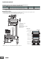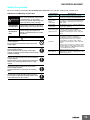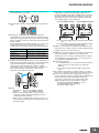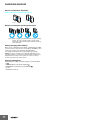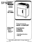
1
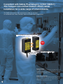
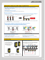
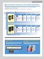
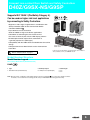
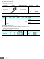
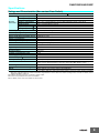
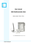
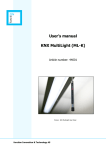
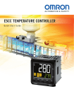
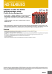
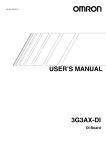
Compact Non-contact Door Switch
D40Z/G9SX-NS/G9SP
Wide range of applications
at the highest safety level
Visible safety
»
Ultimate safety level
»
Versatile applications
Compliant with Safety PLe/Category 4 (ISO 13849-1)
The compact non-contact feature allows easier
installation for a wide range of environments.
The D40Z can be used in work environments under any risk level.
Its combination with safety controllers allows for a wide range of applications.
Electromagnetic Induction Method
Actual
Size
D40Z
Operating distance
(ON
OFF) :
15 mm max.
Mounts on Either Side
Safety Categories
Different types of machines will have different levels of associated risk. As an index
for determining the function to secure safety (safety function) based on the risk
evaluation, the ISO 13849-1 which stipulates safety-related parts of control
systems, categorizes the capability to maintain safety functions in the event of
control system failures as category B to 4.
Performance Level (PL)
An index of the safety control system performance level shared by a person who
implements risk assessment and a person who designs a machine is called
Performance Level (hereinafter abbreviated as "PL") and has 5 levels of evaluation
from "a" to "e".
For details on safety category and PL, refer to page 5.
1
D40Z Features
High level of safety for a wide range of applications
ISO 13849-1 (PLe/Safety Category 4) achieved with Non-contact Door Switches
• Self-diagnostic Function
OMRON’s unique electromagnetic induction system for safety was achieved by implementing a detection function for external wiring
errors in the Switch.
• Redundant internal circuits
The thorough pursuit of safety is evident in mutual checking by double CPUs.
Series connections
• Up 30 Switches can be connected to one Controller while maintaining PLe/safety category 4.
The D40Z can be connected to G9SP or G9SX-NS
Safety Controllers. Select the best model for your application.
Previous configuration
Configuration with the D40Z
Many Controllers
One Controller
Up to 30 Switches
can be connected.
Parallel connections
Series connection
Note 1 : The G9SP supports 2 channels of 15 units each. For more information, refer to Applicable level and the number of connections according to controller
combination on page 5.
Note 2 : Refer to page 16 for details on safety categories (ISO 13849-1).
How PLe/safety category 4 was achieved with series connections
• Safety software monitoring and diagnosis to detect failures
(not possible with series connections of mechanical switches)
Series connections of mechanical switches
Series connections of the D40Z
D40Z
From Controller
D40Z
From Controller
To Controller
Activates
warning
display.
Output OFF
D40Z
To Controller
Monitoring and diagnosis by
safety software enables
detecting errors, such as
short-circuits in D40Z I/O wiring.
Faults may not be detected,
e.g., for short-circuits in
switch I/O wiring.
Electromagnetic induction method
• Enables stable detection
• No adhesion of iron particles
With these electronic switches, stable detection is possible
even when the door closes slowly.
Permanent magnets are not used, so iron is not attracted,
making maintenance easier.
Visible safety
Checking at the production site
Centralized monitoring
The switch's LED indication
patterns make identification of
abnormal condition possible at
the production sites.
Note: For more information,
refer to page 10.
Bipolar NPN/PNP allows for easy connection with any PLC.
The error location can be easily identified. Using a branch
relay for a different pole is not required.
D40Z
PLC
Red LED ON
: Door Open
Red LED Blinking : Error occurred
Auxiliary output
Yellow LED ON
: Door closed (normal)
Yellow LED Blinking : When connected in series;
Other D40Zs are turned
OFF etc.
G9SX-NS
2
For an easier and safer work
environment in all industries.
The application of the D40Z will
continue to increase in all environments.
Automotive manufacturing
(multi-axis robot)
Problem
Detecting the position of a multi-axis
robot is difficult using a limit switch.
Additionally, it is easy to disable the
function.
Solution
The non-contact door switch enables
ease in detecting the robot position
which prevents the operator from easily
disabling the function.
The maintenance work is safer than
ever as the switch conforms to ISO
13849-1 (PLe/safety category 4).
Key
factor
Wide detection area
Safety detection location
Safety detection location
ISO 13849-1 (PLe/Safety Category 4)
FPD
There are too many doors, and it takes
too long to identify the location of a
failure when it occurs.
Solution
Auxiliary output is provided for each
switch. As each switch can be
monitored, it is possible to pinpoint the
location of the failure.
Key
factor
PNP/NPN
Up to 30 units connectable
D40Z
Manufacturing process
PLC
Up to 30 units can
be connected
G9SX-NS
Auxiliary outputs
Problem
3
Position detection of a robot (hazard)
Other Application Examples
Equipment for long production lines
D40Z
D40Z application examples
The D40Z solves problems at the production sites of various industries that require safety
(FPD, automotive parts, food, packaging, multi-axis robot, etc).
The D40Z supports a wide range of risk levels, contributing to a safer environment at
production sites for various industries' applications.
Food
Problem
The machine's small size limits the
space available to install a switch.
Solution
The D40Z's compact size fits into a
narrow space (Switch: 48x48x25 mm,
Actuator: 48x48x17 mm). The D40Z can
be used at an ambient operating
temperature of up to 65°C.
Key
factor
Compact size
Improvement on ambient operating temperature
Automotive parts
Problem
Although safety is ensured with a
contact door switch, particles are
generated which affect product quality.
Solution
With the non-contact door switch D40Z,
no particles will be generated through
friction.
Material processing
D40Z
Manufacturing process for secondary batteries
Other Application Examples
Key
factor
No particles generation
Cleanrooms
D40Z
4
Selectable controllers
A wide range of choices for the versatile applications
A combination of non-contact door switches and safety controllers can be selected according to
the application or the required risk level.
Mounting compatibility with the D40A allows for standardization of machine design.
Non-contact Door Switch
PL/
Safety
Category
Applicable level and the number of connections according to controller combination
Combination
Number of connectable
PL
D40Z Series
(maximum value)
+
D40Z
4
PLe
15 x 2
channels*
G9SX-NS
+
D40Z
4
PLe
30
G9SX-NSA
+
D40Z
4
PLe
30
G9SP
PLe/4
Safety Category
D40Z
Combination
PLd/3
Safety Category
Number of connectable
PL
D40Z Series
(maximum value)
G9SP
+
D40A
3
PLd
15 x 2
channels*
G9SX-NS
+
D40A
3
PLd
30
G9SX-NSA
+
D40A
3
PLd
30
D40A
* G9SP-N10S supports 15 x 1 channel.
Safety Controller
G9SP
Non-contact Door Switch Controller
G9SX-NS
• Combine function blocks for flexible programming
• Extensive system configurations
• Decreased work hours by convenient configurator
• Easy expansion of output points with an expansion unit
• Improved maintainability with LED display
• No special programming required
Function blocks
G9SP Series Catalog
Catalog No.: J181
5
D40A/G9SX-NS Catalog
Catalog No.: C140
Compact non-contact Door Switch and Safety Controllers
D40Z/G9SX-NS/G9SP
Supports ISO 13849-1 (PLe/Safety Category 4).
Can be used on higher risk level applications
by connecting to Safety Controllers.
• Supports a wide range of applications in combination with
Safety Controller G9SP or Non-contact Door Switch
Controller G9SX-NS@.
• Up to 30 units can be connected.
Ideal for middle to large scale device applications.
• Contributes to shortening the time it takes to find
the cause of failure by the switch's LED display patterns.
• Photocoupler monitor output allows connection to
a general-purpose PLC (NPN type).
• Compatibility with the D40A allows standardization of machine
design.
• Compact Non-contact Door Switch can be mounted from
both sides.
Refer to “Safety Precautions” on page 14
Non-contact Door Switch
D40Z
Non-contact Door Switch
Controller G9SX-NS@
Safety Controller
G9SP Series
For the most recent information on models that have been certified for
safety standards, refer to your OMRON website.
Model Number Structure
Model Number Legend
Non-contact Door Switch (Switch/Actuator)
D40Z-@@@
–––
1 2 3
1 Type
1: Standard model (Switch/Actuator)
2 Auxiliary Output
C: 1 NO (Photocoupler Output)
3 Cable length
2: 2 m
5: 5 m
Note: Must be used in combination with a G9SP Safety Controller or G9SX-NS@ Non-contact Door Switch Controller.
For details, refer to G9SP Series Catalog (Cat.No.J181) or D40A/G9SX-NS Catalog (Cat.No.C140).
6
D40Z/G9SX-NS/G9SP
Ordering Information
Non-contact Door Switch
Classification
Appearance
Auxiliary monitoring output
Cable length
Model
2m
D40Z-1C2
5m
D40Z-1C5
Photocoupler outputs *1
Standard models
Note: Must be used in combination with a G9SP Safety Controller or a G9SX-NS@ Non-contact Door Switch Controller.
*1. Photocoupler output. Load current: 10 mA
Non-contact Door Switch Controller G9SX-NS@
Safety outputs *1
OFF-delayed
Instantaneous
*2
Auxiliary
monitoring
output *3
Logical AND Logical AND OFF-delayed
connection connection Max. OFF-delay
input
output
time *4
--
0
2
(Semiconductors)
Rated
voltage
2
(Semiconductors)
1
1
2
(Semiconductors)
24 VDC
3.0 s
Terminal
block type
Model
Screw
terminals
G9SX-NS202-RT
Spring-cage
terminals
G9SX-NS202-RC
Screw
terminals
G9SX-NSA222-T03-RT
Spring-cage
terminals
G9SX-NSA222-T03-RC
Note: For details, refer to the D40A/G9SX-NS Catalog (C140).
*1. P channel MOS FET transistor output
*2. The OFF-delayed output becomes an instantaneous output by setting the OFF-delay time to 0 s.
*3. PNP transistor output
*4. The OFF-delay time can be set in 16 steps as follows:
0/0.2/0.3/0.4/0.5/0.6/0.7/0.8/0.9/1.0/1.2/1.4/1.8/2.0/2.5/3.0 s
Safety Controller G9SP Series
No. of I/O points
Name
Safety Controller
Safety
inputs
Test
outputs
Standard
outputs
10
4
Semiconductor outputs: 4
4
10
6
Semiconductor outputs: 16
--
20
6
Semiconductor outputs: 8
--
Note: For details, refer to the G9SP Catalog (F090).
7
Safety outputs
Unit version
Model
G9SP-N10S
Ver.2.0
G9SP-N10D
G9SP-N20S
D40Z/G9SX-NS/G9SP
Specifications
Ratings and Characteristics (Non-contact Door Switch)
Item
Model
Operating distance (OFF --> ON)
Operating
characteristics
D40Z-1C@
5 mm min. *1
Operating distance (ON --> OFF)
15 mm max. *1
Differential travel
20% or less of operating distance at 23 °C (maximum 2.5mm)
Influence of temperature
20% or less of operating distance at 23 °C within temperature range of -10 to 65 °C
Repeat accuracy
±10% of operating distance at 23 °C
Response time (ON --> OFF) *2
25 ms max.
Operating time (OFF --> ON) *2
100 ms max. (Distance between the switch and actuator is 5 mm)
Ambient operating temperature
-10 to 65 °C (with no icing or condensation)
Ambient operating humidity
25% to 85%
Insulation resistance (between charged parts and case) 50 MΩ max. (at 500 VDC)
Dielectric strength (between charged parts and case)
1,000 VAC for 1 min
Degree of contamination
3
Electromagnetic compatibility
IEC/EN 60497-5-3 compliant
Vibration resistance
10 to 55 to 10 Hz (single amplitude: 0.75 mm, double amplitude: 1.5 mm)
Shock resistance
300 m/s2 min.
Degree of protection
IP67
Material
PBT resin
Mounting method
M4 screws
Terminal screw tightening torque
1 N·m
Power supply voltage
24 V DC +10%/-15%
Power consumption *3
0.5 W max.
Auxiliary monitoring output
Photocoupler output: 24 V DC, load current: 10 mA
LED indicators
Actuator not detected (lights in red); error occurred (blinks in red), actuator detected (lights in
yellow), actuator detected and Non-contact Door Switch input OFF (blinks in yellow)
Connecting cables
2 m, 5 m
Number of connectable switches *4
30 max. (wiring length: 100 m max.)
Weight
Switch: approx. 175 g, actuator: approx. 20 g (D40Z-1C5)
*1. This is the distance where the switch operates from OFF to ON when approaching and the distance where the switch operates from ON to
OFF when separating when the switch and actuator target marks are on the same axis, and the sensing surface coincide. For details, refer to
“Engineering Data” on page 9.
*2. Indicates the value of the non-contact door switch output.
*3. Power to be provided to the load is not included.
*4. For details, refer to item "Precautions for Correct Use".
8
D40Z/G9SX-NS/G9SP
Engineering Data
Guaranteed value and typical data of operating characteristics
15mm *
5mm * 0mm
ON
OFF
* When the switch and actuator target
marks are on the same axis, and the
sensing surfaces coincide.
Unstable range
18
OFF range
16
Operating distance Y (mm)
Operating distance Y (mm)
18
Maximum
operating distance
(ON to OFF)
14
Main lobes
Engineering Data
(ON to OFF)
12
10
Engineering Data
(OFF to ON)
8
Minimum
operating distance
(OFF to ON)
6
OFF range
16
14
Main lobes
12
Engineering Data
(ON to OFF)
10
Engineering Data
(OFF to ON)
8
Minimum
operating distance
(OFF to ON)
6
4
4
Side lobe
(Y<3mm)
2
Side lobe
(Y<3mm)
ON range
2
ON range
0
0
–35 –30 –25 –20 –15 –10 –5
0
5
10
15 20
25
30
–30 –25 –20 –15 –10 –5
35
14
OFF
0
5
10
15 20
25
30
Distance from the target mark on the switch Z (mm)
Distance from the target mark on the switch X (mm)
Operating distance Y (mm)
Maximum
operating distance
(ON to OFF)
Engineering Data
(ON to OFF)
X
Sensing surface
12
ON
10
Engineering Data
(OFF to ON)
8
6
Z*
Y
4
X=0, Z=0
2
Target marks
0
–10°C
23°C
65°C
* The movement of the arrow
direction indicates the positive
direction on the graph.
Effect of ambient temperature (°C)
Note: 1. The operating distance is the distance between the switch and actuator sensing surfaces.
2. Data in the diagram is typical data at an ambient temperature of 23. Actual operating values may vary. The operating distance may be
affected by ambient metal, magnet catches, and temperature.
3. Detection may occur other than on the detection surfaces of the switch and actuator. Before you use the switch and actuator, refer to
“Switch and Actuator Operation” on page 17 to set the detection surfaces of the switch and actuator face to face.
Connections
Internal Connection
D40Z-1C@
Internal circuit
Brown
Blue
White
Black
Yellow
Gray
9
D40Z/G9SX-NS/G9SP
Troubleshooting
LED
indicator
Causes and corrective actions *1
Power supply input may be improperly wired. Check and correct wiring of brown and blue lines. Refer
to “Wiring of Inputs and Outputs” on page 11.
OFF
Fault in power supply
input (brown/blue)
Power supply voltage to D40Z may be insufficient.
Check the power supply voltage (between brown and blue lines) of D40Z fills ratings.
Refer to “Specifications” on page 8.
The wiring length or size of the wire may not be to the specification.
Check the wiring length and size of the wire. Refer to "Precautions for Correct Use".
Noise or
D40Z failure
Red
continuously
Fault in power supply
blinking
input (brown/blue)
Red blinks
once for 2s
Fault in Non-contact
door switch output
(black)
Red blinks Sensing fault
twice for 2s
Fault in Non-contact
Red blinks door switch input
thrice for 2s (white)
Yellow
blinking
There may be excessive noise. Check and correct ambient noise environment.
There may be a failure in internal circuit. Replace with a new D40Z.
Power supply voltage to D40Z may be insufficient.
Check the power supply voltage (between brown and blue cables) of D40Z fills ratings.
Refer to “Specifications” on page 8.
The wiring length or size of the wire may not be to the specification.
Check the wiring length and size of the wire. Refer to "Precautions for Correct Use".
Black line may be shorted to other line.
Check and correct wiring of black line if the black line is shorted to other lines. Refer to “Wiring of Inputs
and Outputs” on page 11.
Invalid actuator may be in a close range to switch.
Use the dedicated actuator.
Faulty signal may be input to white line.
Check and correct wiring of white line. Refer to “Wiring of Inputs and Outputs” on page 11.
OFF state of another
D40Z
Another D40Z may be in OFF state.
Check status of another D40Z connected to the white line and the wiring.
Refer to “Switch and Actuator Operation” on page 17 or “Wiring of Inputs and Outputs” on page 11.
Fault in Non-contact
door switch input
(white)
White line may be disconnected.
Check and correct wiring of white line. Refer to “Wiring of Inputs and Outputs” on page 11.
Red
Actuator fault
Solid-ON *2
Fault in Non-contact
door switch input
(white)
Yellow
Solid-ON *3 Fault in Non-contact
door switch output
(black)
There may be a failure in actuator. Replace with a new D40Z.
White line connected to D1 terminal (test output terminal of G9SP) of G9SX-NS@ may be shorted to
other line. Check and correct wiring of white line connected to D1 terminal (test output terminal of G9SP)
of G9SX-NS@ if the white line is shorted to other lines. Refer to “Wiring of Inputs and Outputs” on
page 11.
Black line connected to D2 terminal (safety input terminal of G9SP) of G9SX-NS@ may be
disconnected. Check and correct wiring of black line connected to D2 terminal (safety input terminal of
G9SP) of G9SX-NS@. Refer to “Wiring of Inputs and Outputs” on page 11.
*1.Another possible cause is a failure in internal circuit. In this case, replace with a new D40Z.
Yet another possible cause is excessive noise. In this case, check and correct ambient noise environment.
*2. The case where the guard door is closed (Switch detects actuator) is indicated.
*3. The case where the system stops though the guard door is closed (Switch detects actuator) is indicated.
10
D40Z/G9SX-NS/G9SP
Dimensions/Wiring
(Unit: mm)
Non-contact Door Switch
D40Z-1C2
D40Z-1C5
Indicator
Cable diameter:
4.2 dia.
Target mark
Sensing surface
Sensing surface
Target mark
1.5
2
12 17
20 25
(7.2 dia.)
(7.2 dia.)
Two 4.2 dia.
Two 7.2 dia.
38
48
7
16
Two 7.2 dia.
38
48
(Actuator)
5.5
10.5
Two 4.2 dia.
16
(Switch)
Non-contact Door Switch D40Z and Non-contact Door Switch Controller G9SX-NS@ or Safety
Controller G9SP Wiring
Example of connection to G9SX-NS@ (Single connection)
Blue
Black
Brown
White
D40Z-1C@
D1 D2 D3 D4
G9SX-NS202
G9SX-NSA222
Example of connection to multiple switches
Example of auxiliary outputs
Connect up to 30 Non-contact Door Switches.
Yellow
24 VDC
COM
Blue
Brown
White
Black
Blue
Brown
White
Black
Blue
Brown
Black
White
PLC etc.
Gray
IN
Yellow
IN
PLC etc.
Gray
COM
24 VDC
Note: The auxiliary output load current must be 10 mA max.
Wrong connection may lead to a failure of the auxiliary output
circuit.
D1 D2 D3 D4
G9SX-NS202
G9SX-NSA222
Wiring of Inputs and Outputs
Signal name
Non-contact Door Switch
power supply input
Cable color
+
Brown
-
Blue
Non-contact door switch input
Non-contact door switch output
Auxiliary monitoring output
11
Description of operation
Supplies power to the D40Z.
White
To set non-contact door switch output in ON state,
non-contact door switch signal input must be in ON state.
Black
Output status depends on statuses of actuator and non-contact door switch signal input.
Yellow
Output status depends on status of actuator.
When a fault is detected, turns into OFF state regardless of actuator status.
Gray
D40Z/G9SX-NS/G9SP
Application Examples
G9SP-N20S(24 VDC) (2-channel Emergency Stop Switch Inputs + Non-contact Door Switch/Manual Reset)
G9SP-N20S
V1
Si0
Si1
Si2
Si3
Si4
G1
T0
T1
T2
T3
T4
Si5
V2
G2
24 VDC
11
S1
S2
21
12
DC24V
Guard
KM1
-NC
KM2
-NC
22
So1
So0
KM1
KM2
S3
Black
White
Brown
Blue
Yellow
Gray
24 VDC
GND
IN
COM
PLC etc.
KM1
GND
KM2
S1: Emergency Stop Switch
S2: Non-contact Door Switch (D40Z)
S3: Reset Switch
KM1, KM2: Contactor
M1: 3-phase motor
M1
Note: 1. The PL and category that correspond to this circuit example vary depending on the program configured to the G9SP-N20S.
For details, refer to "G9SP Series User's Manual (Cat.No.Z922)".
2. For details on terminal arrangement, refer to "G9SP Series User's Manual (Cat.No.Z922)".
3. Wire auxiliary outputs correctly. Incorrect wiring may lead to a failure of the auxiliary output circuit.
G9SX-NSA222-T03-@ (24 VDC) (2-channel Emergency Stop Switch Inputs + Non-contact Door Switch/Manual Reset)
PL/safety category
Model
Stop category
Reset
1
Manual
Non-contact Door Switch D40Z
Non-contact Door Switch Controller G9SX-NSA222-T03-@ (24 VDC)
PLe/4 equivalent
Note: 1. The above PL is only the evaluation result of the example. The PL must be evaluated in an actual application by the customer after confirming the usage conditions.
2. The above PL is the evaluation result concerning the guard. The PL for emergency stop switch and other safety functions must be
separately evaluated.
3. Stopping time is required between when an opening of the guard is detected and when the motor M stops. Use after risk assessment to
prevent operators from approaching hazardous areas too closely during this period.
●Application Overview
•
•
•
•
The S2 monitors the guard, and stop command is sent to the motor controller when the guard is opened.
The power supply to the motor M is turned OFF after OFF-delay time.
The power supply to the motor M is kept OFF while the guard is opened.
The power supply to the motor M is turned ON again when the reset switch S3 is pressed while the guard is closed.
Feedback Loop
KM1
S2
Guard
KM2
11
21
12
22
S2
Blue
Brown
Black
+24 V
White
S1
NC NC
NC
A1
T11 T12 T21 T22
T31 T32 T33
Y1
D1
D2
D3
D4
T41 T42
G9SX-NSA222-T03
AND
Control circuit
OFF
Emergency stop
switch operation
Timing chart
Emergency stop switch S1
A2
S14 S24
S44 S54
L1
X1
X2
D40Z
PLC etc.
24 VDC
KM1 KM2
S14
Motor controller
Reset switch S3
–
KM1, KM2 N.C. contact
KM1
GND
Motor controller
(Operation command)
S1: Emergency Stop Switch
S2: Non-contact Door Switch (D40Z)
S3: Reset Switch
KM1, KM2: Contactor
M1: 3-phase motor
KM1, KM2 N.O. contact
KM2
Operation command
Rotation of motor
M1
OFF-delay time
OFF-delay time
Note: For details, refer to “Safety Category (ISO 13849-1)” on page 16.
12
D40Z/G9SX-NS/G9SP
G9SX-BC202 (24 VDC) (2-channel Emergency Stop Switch Inputs/Manual Reset) +
G9SX-NS202-@ (24 VDC) (Non-contact Door Switch/Auto Reset)
PL/safety category
Model
Stop category
Reset
0
Auto
Non-contact Door Switch D40Z
Non-contact Door Switch Controller G9SX-NSA222-T03-@ (24 VDC)
PLe/4 equivalent
Note: 1. The above PL is only the evaluation result of the example. The PL must be evaluated in an actual application by the customer after confirming the usage conditions.
2. The above PL is the evaluation result concerning the guard. The PL for emergency stop switch and other safety functions must be
separately evaluated.
●Application Overview
• The S3 monitors the guard, and the power supply to the motor M2 is turned OFF immediately when the guard is opened.
• The power supply to the motor M2 is kept OFF while the guard is opened.
• The power supply to the motor M2 is turned ON again when the guard is closed.
11
21
KM1 Feedback Loop
12
22
KM2
S1
S2
+24 V
NC
A1 T11 T12 T21 T22 T31 T32 T33 Y1
KM1
G9SX-BC202
KM2
+24 V
Control circuit
–
M1
A2
S14 S24
L1 L2
KM1 KM2
X1 X2
PLC etc.
Feedback Loop
S3
S1: Emergency Stop Switch
S2: Reset Switch
KM1, KM2: Contactor
M1: 3-phase motor
S3: Non-contact Door Switch (D40Z)
KM3, KM4: Contactor
M2: 3-phase motor
Timing chart
KM3
Guard
KM4
G9SX-BC202 (Upper unit)
Emergency stop switch S1
KM1, KM2 N.C. contact
Blue
Brown
Black
White
Reset switch S2
+24 V
KM1, KM2 N.O. contact
A1
D1
D2
D3
D4
T31 T32 T33
T41 T42
Logical AND output L1
G9SX-NS202
AND
Control circuit
A2
S14 S24
L1
X1
OFF
Rotation of motor M1
G9SX-NS202-@(Lower unit)
X2
Logical AND input T41
PLC etc.
24 VDC
KM3 KM4
KM3
D40Z
–
KM4
KM3, KM4 N.C. contact
KM3, KM4 N.O. contact
GND
M2
Note: For details, refer to “Safety Category (ISO 13849-1)” on page 16
13
Rotation of motor M2
Emergency stop
switch operation
D40Z/G9SX-NS/G9SP
Safety Precautions
Be sure to read the precautions for All Safety Door Switches in the website at:http://www.ia.omron.com/.
Indication and Meaning for Safe Use
WARNING
Indicates a potentially hazardous situation
which, if not avoided, will result in minor
or moderate injury, or may result in
serious injury or death. Additionally there
may be significant property damage.
Precautions
for Safe Use
Supplementary comments on what to do
or avoid doing, to use the product safely.
Precautions
for Correct
Use
Supplementary comments on what to do
or avoid doing, to prevent failure to
operate, or undesirable effect on product
performance.
Control device
Use approved device with direct opening
mechanism complying with IEC/EN 60947-5-1.
Safety
Door Switch,
Safety
Limit Switch
Use approved device with direct opening
mechanism complying with IEC/EN 60947-5-1
and capable of switching micro loads of 24
VDC, 5 mA.
Non-contact
Door Switch
The G9SX-NS must be used with D40Z Noncontact Door Switches.
Relay with forcibly
guided contacts
Use approved devices with forcibly guided
contacts complying with EN 50205.
For feedback, use devices with contacts
capable of switching micro loads of 24 VDC,
5 mA.
Contactor
Use contactors with forcibly guided
mechanism to input the signal to the
Feedback/Reset input of the G9SX-NS
through the NC contact of the contactor.
For feedback, use devices with contacts
capable of switching micro loads of 24 VDC,
5 mA.
Failure to open contacts of a contactor cannot
be detected by connecting NC contact of the
contactor without a forcibly guided mechanism
to the Feedback/Reset input.
Other devices
Evaluate whether devices used are
appropriate to satisfy the requirements of the
safety category level.
WARNING
Serious injury may possibly occur due to breakdown
of safety outputs.
Do not connect loads beyond the rated value to the
safety outputs.
Serious injury may possibly occur due to loss of
required safety functions.
Wire the Edge Controller properly so that supply
voltages or voltages for loads do NOT touch the safety
outputs accidentally.
Requirements
Emergency Stop
Switch
Serious injury may possibly occur due to breakdown
of safety outputs.
Apply protection circuitry against back electromotive
force in case connecting inductive loads to safety
outputs.
Serious injury may possibly occur due to loss of
required safety functions.
Use appropriate devices referring to the following
table.
The machine may start operating and may result in
serious injury or death. Do not put the actuator close
to the switch when the door is open.
14
D40Z/G9SX-NS/G9SP
Precautions for Safe Use
Precautions for Correct Use
1. Disconnect the G9SX-NS from the power supply when wiring the
D40Z.Devices connected to the product may operate
unexpectedly.
2. Do not operate the product in atmospheres containing flammable
or explosive gas.
3. Wire conductors correctly and verify the operation of the product
before using the system in which the product is incorporated.
Incorrect wiring may lead to loss of safety functions.
4. Auxiliary monitoring outputs are NOT safety outputs. Do not use
auxiliary monitoring outputs as safety outputs. Such incorrect use
will cause loss of safety function of D40Z and peripheral devices.
5. After installing the D40Z, qualified personnel must confirm the
installation, and must conduct test operations and maintenance.
The qualified personnel must be qualified and authorized to secure
safety at each phases of design, installation, running,
maintenance, and disposal of the system.
6. A qualified person in charge, who is familiar with the machine in
which the D40Z is to be installed, must conduct and verify the
installation.
7. Be sure to inspect the D40Z daily and every 6 months. Otherwise,
serious injury may possibly occur due to system malfunctions.
8. Do not dismantle, repair, or modify the product. Doing so may lead
to loss of safety functions.
9. Do not apply DC voltages exceeding the rated voltages, nor any
AC voltages to D40Z.
10.Use a DC supply satisfying the requirements given below to
prevent electric shock.
- A DC power supply with double or reinforced insulation, for
example, according to IEC/EN 60950 or EN 50178, or a
transformer according to IEC/EN 61558.
- A DC supply satisfying the requirements for class 2 circuits or
limited voltage/current circuits stated in UL 508.
11.Connect the D40Z to only appropriate components or devices
complying with relevant safety standards corresponding to the
required level of safety category. Conformity to requirements of
the safety category must be determined for the entire system. It is
recommended to consult an authorized certification body
regarding assessment of conformity to the required safety level.
1. The D40Z must be used with a designated actuator and controller
to comply with EN ISO 13849-1.
2. Handle with care
Do not drop the product or expose it to excessive vibration or
mechanical shock. The product may be damaged and may not
function properly.
3. Storage and operating conditions
Do not store or use the products under the following conditions.
1.In direct sunlight
2.At ambient temperatures not between -10 and 65°C
3.At relative humidity not between 25% and 85%
4.In corrosive or combustible gases
5.Where subject to vibration or mechanical shock beyond the
rated values
6.Where subject to contact with oil or chemicals
7.In an atmosphere containing excessive dust, saline, or metal
powder
8.Where iron filings or powder may fall on the product
4. Do not use D40Z at altitudes over 1,000 meters.
5. Do not use to connect other switches or sensors to the wire
conductors of D40Z.
6. Disconnect D40Z and the controller connected to D40Z from
power supply when replacing D40Z. Failure to do so may cause
unexpected operation of devices connected to D40Z.
7. Keep D40Z from solvent such as alcohol, thinner, trichloroethane
or gasoline. Such solvents make the marking on D40Z illegible and
cause deterioration of parts.
8. Do not use D40Z in the magnetic field of 1.5 mT or more, otherwise
D40Z may not function properly.
9. Do not use D40Z in the water or continuous water exposure
environment, otherwise water may leak into D40Z. (An enclosure
of IP67 rating, which D40Z is rated, protects against temporary
immersion in water.)
10.Do not use D40Z switch or actuator as a stopper. Use a stopper to
protect the switch and the actuator. Keep a distance of at least 1
mm between the switch and the actuator.
11.Be sure to install D40Z switch and actuator in such as appropriate
distance that does not create a gap accessible to the hazard.
15
D40Z/G9SX-NS/G9SP
12.When installing two or more adjacent switches, keep a distance of
at least 50 mm from one another.
50 mm min.
17.Use cables of a total length of 100 m max. to connect multiple
D40Z switches. However, the total length of 200 m max. is
possible depending on the number of D40Z switches connected.
The supply voltage to D40Z may decrease by the voltage drop
depending on the cable or the wiring configuration. Check the
power-supply voltage is in the rated range.
30 or less D40Z connected
15 or less D40Z connected
13.Be sure that the machine is stopped whenever the guard door is
open.
(Note 1)
Total wiring length 200 m max.
Total wiring length 100 m max.
14.Mounting the switch and actuator on metal may affect the
operating distance. If there nearby devices that generate strong
radio waves or magnetic fields, they may also affect the operating
distance through the metal. Do not mount the switch and actuator
directly on metal.
When installing them on a metallic material, be sure to verify such
an effect before using. Refer to the following table for the
estimated effects of mounting on metal on the operating distance.
Type of metal
Operating distance
Iron
Approx. 75% of normal distance
Aluminum
Approx. 85% of normal distance
Stainless steel
Approx. 85% of normal distance
We recommend that you separate the switch and actuator at least
10 mm from all nearby metal.
15.Use M4 screws with a maximum diameter of 7mm and washers to
install the switch and actuator. Tighten the screws with a specified
torque. After installing and commissioning, coat the switchactuator fixing screws with tamper-proof varnish or similar
compound for locking. Using anaerobic locking compounds can
have a detrimental effect on the plastic switch case if the
compounds contact with the switch case.
Actuator
1.0N·m
Switch
(Note 1)
(Note 1)
D1 D2 D3 D4
(Note 2)
G9SX-NS202
G9SX-NSA222
D1 D2 D3 D4
(Note 2)
G9SX-NS202
G9SX-NSA222
Note 1.The wiring length between the products must be 100 m
max.
Note 2.For details on connection terminal and wiring of G9SP,
refer to the G9SP Manual (Cat.No.Z922).
18.D40Z is a class A product. In residential areas D40Z may cause
radio interference, in which case the user may be required to take
adequate measures to reduce interference.
19.D40Z may not function properly in surrounding environment with
strong electromagnetic equipment such as RFID system,
proximity sensor, motor, inverter, and switching power supply. If
you use D40Z near such equipment, be sure to verify effects of
such equipment on D40Z before using.
20.Handle cables with care:
1. For bending cables, it is recommended to bend them with a
radius of bend no less than six times the cable outer
diameter.
2. Do not apply a tensile strength of 50N or greater to the
cables.
21.To determine safety distance to hazards, take into account the
delay of non-contact door switch output caused the response time.
22.If there is any machine that has a large surge current (e.g., a
motor) near D40Z, connected a surge absorber to D40Z between
the blue and the other cables (white, black and brown)
respectively, or between the yellow cable and gray cable.
Suggested surge absorber's specification is as follows:
- Peak pulse power: 600 W (10/1000 μs) or more
(Per IEC 61000-4-5 (surge immunity))
- Breakdown voltage: 27-33 V
16.Wiring
1. Stranded wire : 0.2 to 2.5 mm AWG24 to AWG12
Solid wire
: 0.2 to 2.5 mm AWG24 to AWG12
2. When not using auxiliary output, cut off the unused
conductors and protect by insulating-taping to prevent
contacting with other terminals.
3. When you use an additional cable of 20 m or longer, use a
multiconductor cable to group the white, black, brown, and
blue lines together.
16
D40Z/G9SX-NS/G9SP
Switch and Actuator Operation
Switch and Actuator Mounting Directions
Switch
Switch
Actuator
Actuator
Switch and actuator operating directions
Note 1
Note 1.When using the operating direction along the sensing
surface, be sure to provide a gap of at least 3 mm
between the switch and actuator to eliminate the effects
of the side lobes.
Safety Category (ISO 13849-1)
When used in combination with the G9SP or G9SX-NS@, the D40Z
can be used for the environments corresponding to performance level
e and safety category 4 as required by EN ISO 13849-1.
The settings are determined by circuit examples provided by
OMRON, however, and may not be applicable depending on the
operating conditions. Performance levels and safety categories are
determined for the safety control system as a whole. You must
confirm conformity for the entire system.
Approved Standards
- EN ISO 13849-1: 2008 PLe/Safety Category 4 (used with G9SXNS@)
- IEC/EN 61508 SIL 3 (used with G9SX-NS@)
- IEC/EN 60947-5-3 PDF-M (used with G9SX-NS@)
- UL 508
- CAN/CSA C22.2 No.14
17
Terms and Conditions of Sale
1. Offer; Acceptance. These terms and conditions (these "Terms") are deemed
part of all quotes, agreements, purchase orders, acknowledgments, price lists,
catalogs, manuals, brochures and other documents, whether electronic or in
writing, relating to the sale of products or services (collectively, the "Products")
by Omron Electronics LLC and its subsidiary companies (“Omron”). Omron
objects to any terms or conditions proposed in Buyer’s purchase order or other
documents which are inconsistent with, or in addition to, these Terms.
2. Prices; Payment Terms. All prices stated are current, subject to change without notice by Omron. Omron reserves the right to increase or decrease prices
on any unshipped portions of outstanding orders. Payments for Products are
due net 30 days unless otherwise stated in the invoice.
3. Discounts. Cash discounts, if any, will apply only on the net amount of invoices
sent to Buyer after deducting transportation charges, taxes and duties, and will
be allowed only if (i) the invoice is paid according to Omron’s payment terms
and (ii) Buyer has no past due amounts.
4. Interest. Omron, at its option, may charge Buyer 1-1/2% interest per month or
the maximum legal rate, whichever is less, on any balance not paid within the
stated terms.
5. Orders. Omron will accept no order less than $200 net billing.
6. Governmental Approvals. Buyer shall be responsible for, and shall bear all
costs involved in, obtaining any government approvals required for the importation or sale of the Products.
7. Taxes. All taxes, duties and other governmental charges (other than general
real property and income taxes), including any interest or penalties thereon,
imposed directly or indirectly on Omron or required to be collected directly or
indirectly by Omron for the manufacture, production, sale, delivery, importation, consumption or use of the Products sold hereunder (including customs
duties and sales, excise, use, turnover and license taxes) shall be charged to
and remitted by Buyer to Omron.
8. Financial. If the financial position of Buyer at any time becomes unsatisfactory
to Omron, Omron reserves the right to stop shipments or require satisfactory
security or payment in advance. If Buyer fails to make payment or otherwise
comply with these Terms or any related agreement, Omron may (without liability and in addition to other remedies) cancel any unshipped portion of Products sold hereunder and stop any Products in transit until Buyer pays all
amounts, including amounts payable hereunder, whether or not then due,
which are owing to it by Buyer. Buyer shall in any event remain liable for all
unpaid accounts.
9. Cancellation; Etc. Orders are not subject to rescheduling or cancellation
unless Buyer indemnifies Omron against all related costs or expenses.
10. Force Majeure. Omron shall not be liable for any delay or failure in delivery
resulting from causes beyond its control, including earthquakes, fires, floods,
strikes or other labor disputes, shortage of labor or materials, accidents to
machinery, acts of sabotage, riots, delay in or lack of transportation or the
requirements of any government authority.
11. Shipping; Delivery. Unless otherwise expressly agreed in writing by Omron:
a. Shipments shall be by a carrier selected by Omron; Omron will not drop ship
except in “break down” situations.
b. Such carrier shall act as the agent of Buyer and delivery to such carrier shall
constitute delivery to Buyer;
c. All sales and shipments of Products shall be FOB shipping point (unless otherwise stated in writing by Omron), at which point title and risk of loss shall
pass from Omron to Buyer; provided that Omron shall retain a security interest in the Products until the full purchase price is paid;
d. Delivery and shipping dates are estimates only; and
e. Omron will package Products as it deems proper for protection against normal handling and extra charges apply to special conditions.
12. Claims. Any claim by Buyer against Omron for shortage or damage to the
Products occurring before delivery to the carrier must be presented in writing
to Omron within 30 days of receipt of shipment and include the original transportation bill signed by the carrier noting that the carrier received the Products
from Omron in the condition claimed.
13. Warranties. (a) Exclusive Warranty. Omron’s exclusive warranty is that the
Products will be free from defects in materials and workmanship for a period of
twelve months from the date of sale by Omron (or such other period expressed
in writing by Omron). Omron disclaims all other warranties, express or implied.
(b) Limitations. OMRON MAKES NO WARRANTY OR REPRESENTATION,
EXPRESS OR IMPLIED, ABOUT NON-INFRINGEMENT, MERCHANTABIL-
14.
15.
16.
17.
18.
ITY OR FITNESS FOR A PARTICULAR PURPOSE OF THE PRODUCTS.
BUYER ACKNOWLEDGES THAT IT ALONE HAS DETERMINED THAT THE
PRODUCTS WILL SUITABLY MEET THE REQUIREMENTS OF THEIR
INTENDED USE. Omron further disclaims all warranties and responsibility of
any type for claims or expenses based on infringement by the Products or otherwise of any intellectual property right. (c) Buyer Remedy. Omron’s sole obligation hereunder shall be, at Omron’s election, to (i) replace (in the form
originally shipped with Buyer responsible for labor charges for removal or
replacement thereof) the non-complying Product, (ii) repair the non-complying
Product, or (iii) repay or credit Buyer an amount equal to the purchase price of
the non-complying Product; provided that in no event shall Omron be responsible for warranty, repair, indemnity or any other claims or expenses regarding
the Products unless Omron’s analysis confirms that the Products were properly handled, stored, installed and maintained and not subject to contamination, abuse, misuse or inappropriate modification. Return of any Products by
Buyer must be approved in writing by Omron before shipment. Omron Companies shall not be liable for the suitability or unsuitability or the results from the
use of Products in combination with any electrical or electronic components,
circuits, system assemblies or any other materials or substances or environments. Any advice, recommendations or information given orally or in writing,
are not to be construed as an amendment or addition to the above warranty.
See http://www.omron247.com or contact your Omron representative for published information.
Limitation on Liability; Etc. OMRON COMPANIES SHALL NOT BE LIABLE
FOR SPECIAL, INDIRECT, INCIDENTAL, OR CONSEQUENTIAL DAMAGES,
LOSS OF PROFITS OR PRODUCTION OR COMMERCIAL LOSS IN ANY
WAY CONNECTED WITH THE PRODUCTS, WHETHER SUCH CLAIM IS
BASED IN CONTRACT, WARRANTY, NEGLIGENCE OR STRICT LIABILITY.
Further, in no event shall liability of Omron Companies exceed the individual
price of the Product on which liability is asserted.
Indemnities. Buyer shall indemnify and hold harmless Omron Companies and
their employees from and against all liabilities, losses, claims, costs and
expenses (including attorney's fees and expenses) related to any claim, investigation, litigation or proceeding (whether or not Omron is a party) which arises
or is alleged to arise from Buyer's acts or omissions under these Terms or in
any way with respect to the Products. Without limiting the foregoing, Buyer (at
its own expense) shall indemnify and hold harmless Omron and defend or settle any action brought against such Companies to the extent based on a claim
that any Product made to Buyer specifications infringed intellectual property
rights of another party.
Property; Confidentiality. Any intellectual property in the Products is the exclusive property of Omron Companies and Buyer shall not attempt to duplicate it
in any way without the written permission of Omron. Notwithstanding any
charges to Buyer for engineering or tooling, all engineering and tooling shall
remain the exclusive property of Omron. All information and materials supplied
by Omron to Buyer relating to the Products are confidential and proprietary,
and Buyer shall limit distribution thereof to its trusted employees and strictly
prevent disclosure to any third party.
Export Controls. Buyer shall comply with all applicable laws, regulations and
licenses regarding (i) export of products or information; (iii) sale of products to
“forbidden” or other proscribed persons; and (ii) disclosure to non-citizens of
regulated technology or information.
Miscellaneous. (a) Waiver. No failure or delay by Omron in exercising any right
and no course of dealing between Buyer and Omron shall operate as a waiver
of rights by Omron. (b) Assignment. Buyer may not assign its rights hereunder
without Omron's written consent. (c) Law. These Terms are governed by the
law of the jurisdiction of the home office of the Omron company from which
Buyer is purchasing the Products (without regard to conflict of law principles). (d) Amendment. These Terms constitute the entire agreement between
Buyer and Omron relating to the Products, and no provision may be changed
or waived unless in writing signed by the parties. (e) Severability. If any provision hereof is rendered ineffective or invalid, such provision shall not invalidate
any other provision. (f) Setoff. Buyer shall have no right to set off any amounts
against the amount owing in respect of this invoice. (g) Definitions. As used
herein, “including” means “including without limitation”; and “Omron Companies” (or similar words) mean Omron Corporation and any direct or indirect
subsidiary or affiliate thereof.
Certain Precautions on Specifications and Use
1. Suitability of Use. Omron Companies shall not be responsible for conformity
with any standards, codes or regulations which apply to the combination of the
Product in the Buyer’s application or use of the Product. At Buyer’s request,
Omron will provide applicable third party certification documents identifying
ratings and limitations of use which apply to the Product. This information by
itself is not sufficient for a complete determination of the suitability of the Product in combination with the end product, machine, system, or other application
or use. Buyer shall be solely responsible for determining appropriateness of
the particular Product with respect to Buyer’s application, product or system.
Buyer shall take application responsibility in all cases but the following is a
non-exhaustive list of applications for which particular attention must be given:
(i) Outdoor use, uses involving potential chemical contamination or electrical
interference, or conditions or uses not described in this document.
(ii) Use in consumer products or any use in significant quantities.
(iii) Energy control systems, combustion systems, railroad systems, aviation
systems, medical equipment, amusement machines, vehicles, safety equipment, and installations subject to separate industry or government regulations.
(iv) Systems, machines and equipment that could present a risk to life or property. Please know and observe all prohibitions of use applicable to this Product.
NEVER USE THE PRODUCT FOR AN APPLICATION INVOLVING SERIOUS
RISK TO LIFE OR PROPERTY OR IN LARGE QUANTITIES WITHOUT
ENSURING THAT THE SYSTEM AS A WHOLE HAS BEEN DESIGNED TO
2.
3.
4.
5.
ADDRESS THE RISKS, AND THAT THE OMRON’S PRODUCT IS PROPERLY RATED AND INSTALLED FOR THE INTENDED USE WITHIN THE
OVERALL EQUIPMENT OR SYSTEM.
Programmable Products. Omron Companies shall not be responsible for the
user’s programming of a programmable Product, or any consequence thereof.
Performance Data. Data presented in Omron Company websites, catalogs
and other materials is provided as a guide for the user in determining suitability and does not constitute a warranty. It may represent the result of Omron’s
test conditions, and the user must correlate it to actual application requirements. Actual performance is subject to the Omron’s Warranty and Limitations
of Liability.
Change in Specifications. Product specifications and accessories may be
changed at any time based on improvements and other reasons. It is our practice to change part numbers when published ratings or features are changed,
or when significant construction changes are made. However, some specifications of the Product may be changed without any notice. When in doubt, special part numbers may be assigned to fix or establish key specifications for
your application. Please consult with your Omron’s representative at any time
to confirm actual specifications of purchased Product.
Errors and Omissions. Information presented by Omron Companies has been
checked and is believed to be accurate; however, no responsibility is assumed
for clerical, typographical or proofreading errors or omissions.
OMRON AUTOMATION AND SAFETY • THE AMERICAS HEADQUARTERS • Chicago, IL USA • 847.843.7900 • 800.556.6766 • www.omron247.com
OMRON CANADA, INC. • HEAD OFFICE
Toronto, ON, Canada • 416.286.6465 • 866.986.6766 • www.omron247.com
OMRON ARGENTINA • SALES OFFICE
Cono Sur • 54.11.4783.5300
OMRON ELECTRONICS DE MEXICO • HEAD OFFICE
México DF • 52.55.59.01.43.00 • 01-800-226-6766 • [email protected]
OMRON CHILE • SALES OFFICE
Santiago • 56.9.9917.3920
OMRON ELECTRONICS DE MEXICO • SALES OFFICE
Apodaca, N.L. • 52.81.11.56.99.20 • 01-800-226-6766 • [email protected]
OTHER OMRON LATIN AMERICA SALES
54.11.4783.5300
OMRON ELETRÔNICA DO BRASIL LTDA • HEAD OFFICE
São Paulo, SP, Brasil • 55.11.2101.6300 • www.omron.com.br
OMRON EUROPE B.V. • Wegalaan 67-69, NL-2132 JD, Hoofddorp, The Netherlands. • +31 (0) 23 568 13 00 • www.industrial.omron.eu
Authorized Distributor:
Automation Control Systems
• Machine Automation Controllers (MAC) • Programmable Controllers (PLC)
• Operator interfaces (HMI) • Distributed I/O • Software
Drives & Motion Controls
• Servo & AC Drives • Motion Controllers & Encoders
Temperature & Process Controllers
• Single and Multi-loop Controllers
Sensors & Vision
• Proximity Sensors • Photoelectric Sensors • Fiber-Optic Sensors
• Amplified Photomicrosensors • Measurement Sensors
• Ultrasonic Sensors • Vision Sensors
Industrial Components
• RFID/Code Readers • Relays • Pushbuttons & Indicators
• Limit and Basic Switches • Timers • Counters • Metering Devices
• Power Supplies
Safety
• Laser Scanners • Safety Mats • Edges and Bumpers • Programmable Safety
Controllers • Light Curtains • Safety Relays • Safety Interlock Switches
C227I-E-01
02/15
Note: Specifications are subject to change.
Printed on recycled paper.
© 2015 Omron Electronics LLC
Printed in U.S.A.