1
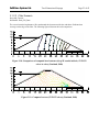
2D / 3D Seepage Modeling Software
Verification Manual
ED-5C
Date: January 27, 2006
Written by:
Robert Thode, B.Sc.G.E.
Jason Stianson, B.Sc.C.E.
Edited by:
Murray Fredlund, Ph.D., P.Eng.
SoilVision Systems Ltd.
Saskatoon, Saskatchewan, Canada
Software License
The software described in this manual is furnished under a license agreement. The software may be used or
copied only in accordance with the terms of the agreement.
Software Support
Support for the software is furnished under the terms of a support agreement.
Copyright
Information contained within this Verification Manual is copyrighted and all rights are reserved by SoilVision
Systems Ltd. The SVFLUX software is a proprietary product and trade secret of SoilVision Systems. The
User’s Manual may be reproduced or copied in whole or in part by the software licensee for use with running
the software. The User’s Manual may not be reproduced or copied in any form or by any means for the
purpose of selling the copies.
Disclaimer of Warranty
SoilVision Systems Ltd. reserves the right to make periodic modifications of this product without obligation to
notify any person of such revision. SoilVision does not guarantee, warrant, or make any representation
regarding the use of, or the results of, the programs in terms of correctness, accuracy, reliability, currentness, or
otherwise; the user is expected to make the final evaluation in the context of his (her) own problems.
Trademarks
Windows™ is a registered trademark of Microsoft Corporation.
SoilVision® is a registered trademark of SoilVision Systems Ltd.
SVFLUX ® is a trademark of SoilVision Systems Ltd.
FlexPDE® is a registered trademark of PDE Solutions Inc.
Surfer® is a registered trademark of Golden Software Inc.
Slicer Dicer® is a registered trademark of Visualogic Inc.
Copyright © 2006
by
SoilVision Systems Ltd.
Saskatoon, Saskatchewan, Canada
ALL RIGHTS RESERVED
Printed in Canada
SoilVision Systems Ltd.
1
2
3
4
5
6
Table of Contents
Page 3 of 62
INTRODUCTION ......................................................................................................................... 4
ONE-DIMENSIONAL SEEPAGE................................................................................................ 5
2.1
TRANSIENT STATE......................................................................................................... 5
2.1.1 Haverkamp (1977) ....................................................................................................... 5
2.1.2 Celia (1990)................................................................................................................. 6
2.1.3 1D Mass Balance ....................................................................................................... 6
2.1.4 SoilCover Comparison................................................................................................. 7
2.1.5 Evaporation – Wilson (1990).................................................................................... 12
2.1.6 Evapotranspiration – Tratch (1995).......................................................................... 14
TWO-DIMENSIONAL SEEPAGE ............................................................................................. 17
3.1
STEADY STATE............................................................................................................. 17
3.1.1 2D Cutoff ................................................................................................................... 17
3.1.2 2D Earth Fill Dam ................................................................................................... 21
3.1.3 X Component of Left to Right Flow..................................................................... 24
3.1.4 Simple Water Balance.............................................................................................. 26
3.1.5 Decreasing Pipe Size............................................................................................... 27
3.1.6 Axisymmetric Verification........................................................................................... 28
3.1.7 Drain-Down Verification ............................................................................................. 29
3.1.8 Highway Subgrade Infiltration................................................................................... 32
3.1.9 Refraction Flow Example.......................................................................................... 38
3.1.10 Axisymmetric Aquifer Pumping Well ....................................................................... 39
3.1.11 Dam Flow .................................................................................................................. 39
3.1.12 Dupuit Problem.......................................................................................................... 40
3.2
TRANSIENT STATE....................................................................................................... 42
3.2.1 Transient Reservoir Filling........................................................................................ 42
3.2.2 Celia Infiltration Example.......................................................................................... 47
3.2.3 Evapotranspiration – Triangular and Rectangular Root Distributions................... 49
THREE-DIMENSIONAL SEEPAGE.......................................................................................... 52
4.1
STEADY STATE............................................................................................................. 52
4.1.1 Flux Section Verification........................................................................................... 52
4.1.2 Wedge Example ........................................................................................................ 53
4.1.3 Cube, Wedge, and Toe Example........................................................................... 55
4.2
TRANSIENT STATE....................................................................................................... 55
4.2.1 Cube, Wedge, and Toe Transient Example.......................................................... 56
4.2.2 Drain-Down Example................................................................................................. 56
4.2.3 Cube Drain-Down Example ...................................................................................... 57
REFERENCES.......................................................................................................................... 59
INDEX ....................................................................................................................................... 61
SoilVision Systems Ltd.
Introduction
Page 4 of 62
1 INTRODUCTION
Extesnive work has gone into the verification of the SVFlux software package. The following problems
represent comparisons made to textbook solutions, hand calculations, and other software packages. We at
SoilVision Systems, Ltd. are dedicated to providing our clients with reliable and tested software. While the
following list of example problems is comprehensive, it does not reflect the entirety of problems which may be
posed to the SVFlux software. It is our recommendation that water balance checking be performed on all model
runs prior to presentation of results. It is also our recommendation that the modeling processmove from simple
to complex models with simpler models being verified through the use of hand calculations or simple
spreadsheet calculations.
SoilVision Systems Ltd.
One-Dimensional Seepage
Page 5 of 62
2 ONE-DIMENSIONAL SEEPAGE
The following examples compare the results of SVFlux against published 1D solutions presented in textbooks
or journal papers. One-dimensional scenarios were entered in SVFlux through the use of a thin 1D column.
2.1 TRANSIENT STATE
Transient or time-dependent problems allow the benchmarking of time-stepping aspects of the SVFlux
software.
2.1.1
Haverkamp (1977)
The Haverkamp (1977) problem involves infiltration into a 1D column of soil. A series of infiltration
experiments were performed by Haverkamp in the laboratory using a plexiglass column uniformly packed with
sand to verify the numerical results. The problem was originally solved using 1D finite element and 1D finite
difference solution methods. Time-steps used in the analysis were varied in the original work to determine their
effect on the solution. The best solution presented is with small time-steps (10 seconds) and a dense grid.
The soil properties used in Haverkamp’s analysis were custom equations defined in terms of elevation head
rather than soil suction. The problem was initially set up in SVFlux and then minor modifications were made to
the finite element script file to duplicate the solution exactly. The script file presenting the exact comparison of
results can be provided upon request.
The results of the comparison may be seen in Figure 2-1. Previous issues with varying timesteps are rendered
insignificant given the automatic time-step refinement present in the SVFlux software. It can be seen that the
mesh selected by SVFlux automatically duplicates the best results presented by the Haverkamp solution. The
solution took 26 seconds on a P-4 2.8GHz computer and used a total of 604 nodes.
-10
Pressure head (cm)
-20
-30
dt = 10 sec
dt = 30 sec
dt = 120 sec
-40
Dense Grid
SVFlux
-50
-60
-70
0
5
10
15
20
25
30
35
40
Depth (cm)
Figure 2-1 Comparison between SVFlux and Haverkamp (1977) as presented by Celia (1990)
in Fig. 1b
SoilVision Systems Ltd.
2.1.2
One-Dimensional Seepage
Page 6 of 62
Celia (1990)
Celia (1990) performed comparisons of 1D solvers by varying the time-steps and the solution methods (finite
difference or finite element). His results are considered classic solutions and are commonly used to benchmark
the validity of 1D infiltration problems. The solution presented by Celia used the H-based formulation of
Richard’s equation and a Newton-Raphson iterative method.
A replica of Celia’s problem was set up using the SVFlux software. Celia presented the soil properties for the
problem as van Genuchten’s equation for the soil-water characteristic curve and as van Genuchten and
Mualem’s equation for representing the unsaturated hydraulic conductivity curve. Since both methods are
implemented in the SVFlux software the parameters used for the soil could be input directly.
The results of the comparison may be seen in Figure 2-2. As in the previous problem it can be seen that the
automatic mesh generation and automatic time-step refinement allow quick convergence to the correct solution.
A solution for this problem was achieved in 43 minutes using an average of 897 nodes.
Project:?
Problem:?
0
Pressure head (cm)
-200
Dense Grid
-400
dt = 20 sec
dt = 2.4 min
-600
dt = 12 min
dt = 60 min
-800
SVFlux
-1000
-1200
0
20
40
60
80
100
Depth (cm)
Figure 2-2 Comparison between SVFlux and results presented by Celia (1990)
2.1.3
1D Mass Balance
An infiltration problem was created which verifies the mass-balance of a simulated rainfall for a period of 1
day. A single storm event is input into SVFlux and a 24-hour period is run. The reported total flow into the 1D
column should be equal to the amount of rainfall if calculations are correct. Zero flux boundaries on three sides
of the problem disallow any flux in or out of the problem with the exception of the top boundary.
SoilVision Systems Ltd.
One-Dimensional Seepage
Page 7 of 62
Project:VerifyPrecipitation
Problem: Day1
Precipitation: 0.1 m3/day/m2
Soil: Grey Till
ksat: 0.9 m/day
Laboratory Interpolated
Fredund and Xing Fit
Laboratory Data
0.45
0.4
0.35
0.3
0.25
0.2
0.15
0.1
0.05
0
1e-3
1e-2
1e-1
1e+0
1e+1
1e+2
1e+3
1e+4
1e+5
1e+6
Soil suction (kPa)
Figure 2-3 Soil-water characteristic curve for 1D mass-balance problem
The results of the 1D problem may be summarized as follows:
Application:
Intensity:
0.1 m3/day/m2 x 0.1m = 0.01 m3/day
start 9:00 am
end 17:00 (5:00pm)
Reported flux in:
0.010043 m3/day
Error:
0.43%
2.1.4
SoilCover Comparison
The question of how the results of SVFlux compare to the traditionally accepted SoilCover program
has surfaced in the past while. The purpose of this set of benchmark problems is to explain the
SoilVision Systems Ltd.
One-Dimensional Seepage
Page 8 of 62
similarities and differences between the two software packages. The primary theoretical difference
is that the current version of SVFlux does not couple in heat flow. How significant is thermal
coupling in standard problems? Two examples are set up and the results of the two programs are
compared in order to attempt to determine computational differences.
A cover scenario was chosen for the comparison and the results are presented in the following
paragraphs.
In this example a 1m cover is placed over a 3m tailings material. The bottom boundary is forced to a
constant suction of –10kPa. The initial conditions are considered hydrostatic through the suction of
–10kPa at elevation zero.
The soil properties for the cover material are as follows.
0.450
1.00E-01
User Points
0.400
1.00E-02
Curve Fit
1.00E-03
Slope Function
0.300
1.00E-04
0.250
1.00E-05
0.200
1.00E-06
0.150
1.00E-07
0.100
1.00E-08
0.050
1.00E-09
0.000
0
0
1
10
100
1000
10000
100000
1.00E-10
1000000
Matric Suction (kPa)
Figure 4 Soil-water characteristic curve for Cover material
Slope Function (1/kPa)
Water Content (dec.)
0.350
SoilVision Systems Ltd.
One-Dimensional Seepage
Page 9 of 62
Matric Suction (kPa)
0
1
10
100
1000
10000
100000
1.00E+00
1.00E-01
1000000
0.50
0.45
1.00E-03
0.40
1.00E-04
0.35
1.00E-05
0.30
1.00E-06
0.25
1.00E-07
1.00E-08
0.20
1.00E-09
1.00E-10
0.15
1.00E-11
0.10
Volumetric Water Content
Relative Permeability
1.00E-02
1.00E-12
0.05
1.00E-13
1.00E-14
0.00
Figure 5 Hydraulic conductivity for the Cover material (ksat=5e-2 cm/s)
Likewise the soil properties for the tailings material are as follows.
1.00E-01
0.500
User Points
0.450
1.00E-02
Curve Fit
1.00E-03
Slope Function
0.350
1.00E-04
0.300
1.00E-05
0.250
1.00E-06
0.200
1.00E-07
0.150
1.00E-08
0.100
1.00E-09
0.050
0.000
0
0
1
10
100
1000
10000
100000
1.00E-10
1000000
Matric Suction (kPa)
Figure 6 Soil-water characteristic curve for the Tailings material
Slope Function (1/kPa)
Water Content (dec.)
0.400
SoilVision Systems Ltd.
0
1.00E+00
1.00E-01
One-Dimensional Seepage
1
10
Matric Suction (kPa)
100
1000
10000
Page 10 of 62
100000
1000000
0.50
0.45
1.00E-03
0.40
1.00E-04
0.35
1.00E-05
1.00E-06
1.00E-07
1.00E-08
0.30
0.25
0.20
1.00E-09
1.00E-10
0.15
1.00E-11
0.10
Volumetric Water Content
Relative Permeability
1.00E-02
1.00E-12
1.00E-13
1.00E-14
0.05
0.00
Figure 7 Hydraulic conductivity for the Tailings material (ksat=5.7e-5 cm/s)
The model is run for a total of 184 days with relative humidity set at 60%. A total of 87 nodes are
used for the SoilCover analysis. Ground temperatures are calculated within SoilCover by looking up
latitudes. Evapotranspiration is included in the SoilCover analysis but does not significantly affect
the end result. Vegetative and freeze/thaw options were turned off in the SoilCover analysis. The
cumulative results of the SoilCover analysis may be seen in the following figure.
SoilVision Systems Ltd.
One-Dimensional Seepage
Page 11 of 62
500
400
300
Flux (mm)
200
100
0
-100
-200
-300
-400
-500
-600
0
20
40
60
PE
AE
PT
80
AT
100
Day
ET
120
Precip
140
160
Run Off
Figure 8 SoilCover results of numerical model with cover
180
Infil.
200
Flux (m)
SoilVision Systems Ltd.
One-Dimensional Seepage
Page 12 of 62
0.5
0.4
0.3
0.2
0.1
0
-0.1
-0.2
-0.3
-0.4
-0.5
-0.6
0
50
100
150
200
Time (days)
PE
AE
Precipitation
Net Flux
Figure 9 SVFLUX results of numerical model with cover
Items to note regarding the comparative analysis are as follows:
•
•
AE separates quickly from PE at around day 33 in the SoilCover analysis. This is
impossible because there has not been enough potential evaporation at this time to drive
suctions up past 3000 kPa. AE and PE only separate past a suction of 3000 kPa (Wilson,
1997)
Generally the results are the same and indicate good agreement between SoilCover and
SVFlux
The source of the difference in the initial split was investigated. It was found that AE and PE split
on approximately day 30 in SoilCover while not splitting until day 38-40 in SVFlux. This variation
results in the difference in the predicted AE between the two packages. The suction profiles at day
46 were plotted for each software package and it was found that the cause of the difference is due to
a single node going to a very high suction (18,000 kPa) in SoilCover. This is an error caused by a
lack of nodal resolution near the upper boundary.
2.1.5
Evaporation – Wilson (1990)
The classic solution to the coupling of soil-atmosphere equations is presented by Wilson (1990). In the PhD
thesis a column of sand was subjected to drying in a laboratory environment in which the temperature and
relative humidity were controlled. Measurements of actual evaporation and the distributions of temperature
SoilVision Systems Ltd.
One-Dimensional Seepage
Page 13 of 62
along the column depth were obtained, providing several measures that can be used for the verification of the
numerical model. A Modified Penman approach to the calculation of actual evaporation was presented in the
thesis. Wilson (1990) coded a 1D finite element package termed “Flux” in order to compare the physical results
to a numerical solution. The geometry and configuration of the column may be seen in the following figure.
Figure 10 Numerical simulation of the drying column test (Wilson, 1990)
An initial comparison to the results obtained by Wilson (1990) was performed by Gitirana (2004) using the
FlexPDE solver used by SVFlux. The FlexPDE formulation presented by Gitirana included full coupling of the
temperature partial differential equations. The results of this work are presented in Figure 11.
Figure 11 Results of Gitirana (2004) as compared to Wilson (1990)
SoilVision Systems Ltd.
One-Dimensional Seepage
Page 14 of 62
The formulation presented in the thesis of Gitirana (2004) was subsequently implemented in the SVFlux
software package. Full coupling of the temperature equations was omitted in the SVFlux implementation as the
influence of temperature flow within the soil is most often a small influence on the evaporative process. The
effect of heat movement within the soil is often negligible unless an extremely large time-frame is being
considered in the analysis.
The experimental results obtained by Wilson (1990) were then again compared to SVFlux. The results are
shown in Figure 12. It can be seen from the results that excellent comparison is obtained. Small “bumps” in the
solution are largely due to the extremely nonlinear nature of this problem.
Project:?
Problem:?
9
Evaporation rate, mm/day
8
7
Potential Evaporation
6
Actual Evaporation, Column A
5
AE, Column B
AE, Flux program (Wilson, 1990)
4
SVFlux
3
2
1
0
0
5
10
15
20
25
30
35
40
Time, Day
Figure 12 Results of SVFlux comparison to laboratory data and finite element program
produced by Wilson (1990)
Solution of the Wilson (1990) problem documents the proper calculation of actual evaporation by SVFlux. It
documents the proper separation between potential evaporation (PE) and actual evaporation (AE).
2.1.6
Evapotranspiration – Tratch (1995)
ProjectID: Evapotranspiration
ProblemID: TratchThesis1D_Final
The evapotranspiration simulations performed by Tratch (1995) examine the effects of a vegetation cover on a
column of soil. The plant cover was allowed to develop over an entire growing season and the measured
evapotranspiration fluxes were used to calibrate a 1D finite element computer model, SoilCover (Mend 1993).
SoilVision Systems Ltd.
One-Dimensional Seepage
Page 15 of 62
The evapotranspiration features of SVFlux were used to duplicate the experimental and numerical results. A
vertical 1D model was set up with a 0.6m depth. An error limit of 0.0001 and 437 nodes were used in the
SVFlux solver to achieve the desired accuracy. The problem was run for an 86 day time period allowing
SVFlux to automatically adjust the time-steps as required.
The base of the model consists of a flow boundary condition using the data from the Tratch thesis in table B.5.
During the experiment the base of the column was held at a constant head, therefore the basal flow rates
represent the water that entered the problem from a reservoir. An initial head = 0 kPa was entered into SVFlux,
which means that the column is fully saturated at the start of the analysis.
An evapotranspiration boundary condition was applied to the top of the model. This caused an evaporative flux
to be applied to the top node and additionally a transpiration sink to be applied below the surface. The
evaporative flux data was entered as potential evaporation as presented by Tratch, then SVFlux computes the
actual evaporation after Wilson (1997). A constant temperature of 20oC and a constant relative humidity of
85% were used in SVFlux instead of the exhaustive diurnal datasets used by Tratch.
The transpiration sink is applied below the surface to a depth corresponding to the root zone. A triangular root
zone distribution was used. The root depth was held at 0 for 2 days and then increased linearly as the growing
season progressed to 0.6m at day 86. The transpiration sink is also a function of the vegetative parameters of
the plant cover. The leaf-area index (LAI) vs. time data (Figure 2-13) modifies the potential evaporation to give
the potential evapotranspiration. The plant limiting function (PLF) determined from moisture limiting point of
100 kPa and a plant wilting point of 200 kPa. As the suction increases in the model the PLF decreases from 1 at
the limiting point to 0 at the wilting point. The calculated transpiration sink in a function of the potential
evapotranspiration, PLF, and active root zone.
5
4.5
4
3.5
LAI
3
2.5
2
1.5
1
0.5
0
0
10
20
30
40
50
60
70
80
90
Time (days)
Figure 2-13 Leaf-Area Index for Evapotranspiration Verification
The column was filled with a uniform silt. Tratch estimated the soil-water characteristic curve (SWCC) for the
silt. The SWCC data was fit with the Fredlund and Xing fit in SVFlux. The resulting parameters are a saturated
volumetric water content of 0.371, an air-entry value of 25, an n parameter of 3, m parameter of 0.58, and hr of
SoilVision Systems Ltd.
One-Dimensional Seepage
Page 16 of 62
137 kPa. A saturated hydraulic conductivity, ksat, of 0.001296 m/day was used for the silt and the unsaturated
hydraulic conductivity is estimated from the SWCC data using the Modified Campbell method with a p = 8 and
a minimum hydraulic conductivity of 1E-9 m/day.
Figure 2-14 shows the results of the SVFlux analysis compared to the measured and computed values presented
by Tratch. The problem was solved in 45 minutes on a Pentium 4 - 2.8 GHz computer. The SVFlux values
compare well to the Tratch analyses. The difference between the evaporation curves is likely due to choice of
exact soil properties and curve fitting parameters. The model is particularly sensitive to hydraulic conductivity
parameters. The lower value of the transpiration sink calculated by SVFlux can be attributed to the same
effects. The divergence of the SVFlux transpiration from the measured values after day 70 is likely due to the
upper limit on the active root zone not considered for the sake of simplicity. Tratch documents a trial and error
method used to calibrate the active root zone in SoilCover to match the measured data.
0.007
Measured potential evaporation
0.006
Computed Evapotranspiration
Flux (m/day)
0.005
0.004
0.003
Computed Transpiration
0.002
SVFlux Transpiration
Measured
Evapotranspiration
0.001
SVFlux Evaporation
Computed Evaporation
0
0
10
20
30
40
50
60
70
Time (days)
Figure 2-14 Comparisons between SVFlux and results presented by Tratch (1995)
80
90
SoilVision Systems Ltd.
Two-Dimensional Seepage
Page 17 of 62
3 TWO-DIMENSIONAL SEEPAGE
An assorted allotment of problems are used to verify the validity of the solutions provided by the SVFlux
software. Comparisons are made either to textbook solutions, journal-published solutions, or other software
packages.
3.1 STEADY STATE
The first steady state problem used to compare the two software packages involves flow beneath a concrete
gravity dam. The second problem involves flow through an earth fill dam. Each scenario begins with a brief
description of the problem followed by a comparison of the results from Seep/W and SVFlux.
3.1.1
2D Cutoff
ProjectID: ExamplesDataOld
ProblemID: Cutoff
Figure 3-1: Mesh from SVFLUX solver (Pentland, 2000)
SoilVision Systems Ltd.
Two-Dimensional Seepage
Page 18 of 62
Figure 3-2: Mesh from Seep/W (Pentland, 2000)
On the left hand side of the problem a reservoir is simulated by applying a head of 60m while on the right side
the water table is placed at the ground surface by setting a head of 40m. All other boundaries are set to zero
flow. Figure 1 provides a view of the mesh automatically created by the SVFLUX solver. With manual
preparation of data for a large and complex problem, the processes of subdivision and generation of error-free
input may be much more costly and time-consuming than the computer execution of the problem according to
Desai and Abel (1972). Automatic mesh generation not only saves time in problem creation but can also show
where the problem gradients are high. In seepage analysis a rapidly changing head can result in high gradients
and these are of utmost importance when analyzing a concrete gravity dam.
Seep/W (version 5.0 and earlier) does not provide fully automatic mesh generation and requires the user to
draw and refine their own mesh. The user may encounter two problems if they do not correctly identify areas
of high gradients and refine the mesh accordingly. The first problem will involve a lack of mesh resolution in
areas of high gradients. Lack of proper mesh refinement decreases the chances of convergence and overall
solution accuracy. The second problem may involve refining the mesh in areas where gradients are minimal.
Unnecessary refinement can result in more nodes than necessary and the problem takes longer than necessary
to solve.
The SVFLUX solver ensure that there is a proper number of nodes at the beginning of the problem. The
SVFLUX solver also goes one step further by offering automatic mesh refinement while the problem is being
analyzed. This ensures that at any time during the problem solution the users can be assured that the
requirements of solution accuracy are being met. These is also a greater assurance that there will be a proper
convergence of your seepage problem.
SoilVision Systems Ltd.
Two-Dimensional Seepage
Page 19 of 62
Figure 3-3: Comparison of computed head contours (Seep/W results in black, SVFLUX solver
in color) (Pentland, 2000)
The comparison of computed head shows that there is good agreement between the SVFLUX solver and
Seep/W. However, attention should be given to two details in Figure 3. The first is the agreement in computed
head near the downstream toe of the dam. From the problem description it can be seen that the mesh drawn in
SVFLUX near the downstream toe has greater resolution than the mesh provided by Seep/W. However, the
heads computed by both software packages are essentially the same. It can be concluded that Seep/W used
more nodes than required to provide the necessary accuracy and solution efficiency in this area. A second
detail is the increasing difference in computed head closer to the cutoff. From Figure 1 and Figure 2 in the
problem description it can be seen that the SVFLUX solver has provided a much denser mesh than Seep/W in
this area. The accuracy of a finite element solution can be improved by one of two methods: either by refining
the mesh, or by selecting higher order displacement models (Desai and Abel, 1972). It appears that the
difference in the solved heads are the result of the denser mesh provided by the SVFLUX solver. While the
differences are small in this problem, the differences may become more apparent in a more complex problem.
SoilVision Systems Ltd.
Two-Dimensional Seepage
Page 20 of 62
Figure 3-4: Computed vectors for SVFLUX solver (Pentland, 2000)
Figure 3-5: Computed vectors for Seep/W (Pentland, 2000)
The comparison of computed gradients shows general agreement between the two software packages.
Hydraulic gradient, according to Darcy’s law is the change in head over a change in length, i = dh / dl (Freeze
and Cherry, 1979). It may be hard to detect in Figure 4 and Figure 5 but there appears to be differences in the
computed gradients for the same reason as stated for the comparison of the computed heads.
SoilVision Systems Ltd.
Two-Dimensional Seepage
Page 21 of 62
Figure 3-6: Comparison of computed pressure contours (Seep/W results in black, SVFLUX
solver in color) (Pentland, 2000)
Pressure is calculated as u = γ * (h − y ) , where γ (Kg/m3) is the unit weight of water, h is hydraulic head (m)
and y (m) is the elevation in a two dimensional analysis. Because the calculation of pressure depends on the
variable, head, it can be expected that there will be slight differences in the calculated pressures for the same
reasons as there are differences in the comparison of head.
3.1.2
2D Earth Fill Dam
The second steady state example used to compare SVFLUX and Seep/W is an earth fill dam. The earth fill
dam is analyzed on two scenarios. The first scenario does not include a filter material near the toe of the dam
and involves the use of a review boundary condition on the downstream face of the dam to determine the length
of the seepage face. The second scenario involves the use of a filter material to ensure that water does not exit
the dam on the downstream face.
3.1.2.1 Review Boundary
ProjectID: ExamplesDataOld
ProblemID: Earth_Dam
The first scenario involves the use of a review by pressure calculation of the olcation of the downstream exit
point. The comparison results may be seen in the following figures.
SoilVision Systems Ltd.
Two-Dimensional Seepage
Page 22 of 62
Figure 3-7: Comparison of computed head contours (Seep/W results in black, SVFLUX solver
in color) (Pentland, 2000)
Figure 3-8: Computed vectors (SVFLUX solver) (Pentland, 2000)
Figure 3-9: Computed vectors (Seep/W) (Pentland, 2000)
SoilVision Systems Ltd.
Two-Dimensional Seepage
Page 23 of 62
3.1.2.2 Filter Scenario
ProjectID: Tutorial
ProblemID: Earth_Fill_Dam
The second scenario implements a filter underneath the downstream side the earth dam. Gradients then
converge on the edge of the filter. The following figures illustrate the result comparison.
Figure 3-10: Comparison of computed head contours (Seep/W results in black, SVFLUX
solver in color) (Pentland, 2000)
Figure 3-11: Computed vectors (SVFLUX solver) (Pentland, 2000)
SoilVision Systems Ltd.
Two-Dimensional Seepage
Page 24 of 62
Figure 3-12: Comparison of computed pressure contours (Seep/W results in black, SVFLUX
solver in color) (Pentland, 2000)
3.1.3
X Component of Left to Right Flow
ProjectID: VerifyFlux
ProblemID: FS_Q1_LeftRight
The following problem verifies the correct calculation of the x component (i.e., horizontal flow) of left-right
flow. This steady-state problem is verified using hand calculations.
SoilVision Systems Ltd.
Two-Dimensional Seepage
Page 25 of 62
Figure 3-13 Setup of left-to-right flow.
Flow calculations by hand are as follows.
Q = kiA Q = kiA
Q = 1E-4 m/s x (4m-3m)/(10m-0m) x 4m x 1m
Q = 4E-5 m3/s
Resultant x flux calculated by SVFLUX across sections Flux 1 and Flux 5 is 4E-5 m3/s (Error = 0.00%)
SoilVision Systems Ltd.
3.1.4
Two-Dimensional Seepage
Page 26 of 62
Simple Water Balance
ProjectID: VerifyFlux
ProblemID: NatBCTest02
The following problem illustrates the verification of flow across a flux section with a slightly irregular shaped
problem. Flow through Flux Section 1 must equal flow out of Flux Section 2 as well as the flux applied to the
boundary at Flux Section 1.
Figure 3-14 Confirmation of flow in and out across flux sections
The total flux applied at Flux Section 1 is equal to 0.01m3/s/ m2 x 2.5m x 1m = 0.025 m3/s. The results of the
flux section comparison are as follows:
Flux_1: -0.02451 m3/s
Flux_2: 0.024821 m3/s
Error: 2.0%
Error: 0.7%
SoilVision Systems Ltd.
3.1.5
Two-Dimensional Seepage
Page 27 of 62
Decreasing Pipe Size
ProjectID: VerifyFlux
ProblemID: Wedge
This example confirms that mass is not lost through a decreasing pipe size. The pipe is 60m high on the left
side and 10m high on the right side. If a mass of water is not lost, then Flux_1 and Flux_2 should be equal. The
total flow through the pipe can also be calculated by hand calculations.
Figure 3-15 Decreasing pipe problem setup.
The computed flow through the problem is:
Q = kiA Q = kiA
Q = 5E-3 m/day x (60m-10m)/(80 m) x (60-(80/3) x 50/80
Q = 5e −3 m / day * (60m − 10m) / 80m * (60 − (1 / 3 * 80) * (50 / 80)
Q = 0.135417 m 3 / day
Results of the analysis are as follows:
Flux_2: 0.136796 m 3 / day Error: -1.0 %
Flux_1: 0.136880 m 3 / day Error: +1.1%
SoilVision Systems Ltd.
3.1.6
Two-Dimensional Seepage
Page 28 of 62
Axisymmetric Verification
ProjectID: Verify
ProblemID: GradChange
This example illustrates the design of a simple box taking the form of an Axisymmetric problem. A head
boundary condition of 11m is placed on the right-hand side of the problem and a head boundary condition of
10m is placed on the left side of the problem. The box dimensions are 10m x 10m.
If the axisymmetric portion of the analysis is being properly considered then two aspects can be observed,
namely:
1.
2.
The gradient in the x direction will increase from right to left, and
The flux sections will display the same value.
Flux 3
Flux 2
Figure 3-16 Axisymmetric analysis check.
The final results from the flux section computations are as follows:
Flux_1: 0.026200 m 3 / s
Flux 1
SoilVision Systems Ltd.
Two-Dimensional Seepage
Page 29 of 62
Flux_2: 0.026189 m 3 / s
3
Flux_3: 0.025805 m / s
The resultant gradient distribution is shown in the following figure. The contours show a constant increase in
flow velocity from right to left.
Figure 3-17 Gradient change in a Axisymmetric problem.
3.1.7
Drain-Down Verification
“Drain down” of water in an unsaturated problem can be particularly prone to errors in water balance
calculations. SVFLUX uses a mass-conservative formulation of the unsaturated flow equation (Celia,
Bouloutas, and Zarba, 1990) intended to minimize the error associated with water balance calculations.
SoilVision Systems Ltd.
Two-Dimensional Seepage
Page 30 of 62
For verification of this problem a square box is described with dimensions of 1m x 1m. Initial conditions are
saturated and water is allowed to drain out of the lower right of the problem by slowly decreasing the head over
the lower 0.1m section of wall. The final head boundary condition on the lower right section is 0.1m. It should
be noted that the drainage boundary condition applied to the lower right should be applied slowly. If the
boundary condition head equal to 0.1m is applied instantaneously at time equal to zero, numerical instability
can result.
A series of five scenarios with five different soil properties were defined and run. The resultant water-balance
error and soil properties are presented in the following tables and figures.
Project:?
Problem:?
Table 1 Scenarios and resultant problem errors.
Problem Title
BoxDrainT1
BoxDrainT2
BoxDrainT3
BoxDrainT5
BoxDrainT6
Start (m^3)
0.350
0.242
0.320
0.301
0.315
End (m^3)
0.0707
0.241888
0.313
0.201
0.2397
Error
3.7%
2.3%
6.2%
4.4%
1.0%
Table 2 Soil properties for case BoxDrainT1.
Laboratory Interpolated
Fredund and Xing Fit
Laboratory Data
Modified Campbell
0.35
1e-3
0.3
1e-4
0.25
1e-5
0.2
1e-6
0.15
1e-7
0.1
1e-8
0.05
0
1e-3
1e-9
1e-2
1e-1
1e+0
1e+1
1e+2
Soil suction (kPa)
1e+3
1e+4
1e+5
1e+6
1e-3
1e-2
1e-1
1e+0
1e+1
1e+2
Soil suction (kPa)
1e+3
1e+4
1e+5
1e+6
SoilVision Systems Ltd.
Two-Dimensional Seepage
Page 31 of 62
Table 3 Soil properties for case BoxDrainT2.
Laboratory Interpolated
Fredund and Xing Fit
Laboratory Data
Modified Campbell
0.25
1e+3
1e+2
1e+1
0.2
1e+0
1e-1
1e-2
0.15
1e-3
1e-4
0.1
1e-5
1e-6
1e-7
0.05
1e-8
1e-9
0
1e-1
1e-10
1e+0
1e+1
1e+2
1e+3
1e+4
1e+5
1e+6
1e+7
1e+8
1e-1
1e+0
1e+1
1e+2
1e+3
Soil suction (psf)
1e+4
1e+5
1e+6
1e+7
1e+8
1e+5
1e+6
1e+7
1e+8
1e+5
1e+6
1e+7
1e+8
Soil suction (psf)
Table 4 Soil properties for case BoxDrainT3.
Laboratory Interpolated
Fredund and Xing Fit
Laboratory Data
Modified Campbell
0.35
1e+2
1e+1
0.3
1e+0
1e-1
0.25
1e-2
0.2
1e-3
1e-4
0.15
1e-5
1e-6
0.1
1e-7
1e-8
0.05
1e-9
0
1e-1
1e-10
1e+0
1e+1
1e+2
1e+3
1e+4
1e+5
1e+6
1e+7
1e+8
1e-1
1e+0
1e+1
1e+2
Soil suction (psf)
1e+3
1e+4
Soil suction (psf)
Table 5 Soil properties for case BoxDrainT5.
Laboratory Interpolated
Fredund and Xing Fit
Laboratory Data
Modified Campbell
0.35
1e+3
1e+2
0.3
1e+1
1e+0
0.25
1e-1
1e-2
0.2
1e-3
1e-4
0.15
1e-5
1e-6
0.1
1e-7
0.05
1e-8
0
1e-10
1e-9
1e-1
1e+0
1e+1
1e+2
1e+3
1e+4
Soil suction (psf)
1e+5
1e+6
1e+7
1e+8
1e-1
1e+0
1e+1
1e+2
1e+3
1e+4
Soil suction (psf)
SoilVision Systems Ltd.
Two-Dimensional Seepage
Page 32 of 62
Table 6 Soil properties for case BoxDrainT6.
Laboratory Interpolated
Fredund and Xing Fit
Laboratory Data
Modified Campbell
0.35
1e+2
1e+1
0.3
1e+0
1e-1
0.25
1e-2
1e-3
0.2
1e-4
0.15
1e-5
1e-6
0.1
1e-7
1e-8
0.05
1e-9
1e-10
0
1e-1
1e+0
1e+1
1e+2
1e+3
1e+4
1e+5
1e+6
1e+7
Soil suction (psf)
3.1.8
1e+8
1e-1
1e+0
1e+1
1e+2
1e+3
1e+4
1e+5
1e+6
1e+7
Soil suction (psf)
Highway Subgrade Infiltration
The following scenarios are comparisons to Seep/W solutions previously published at the Canadian
Geotechnical Conference in Toronto (Barbour, Fredlund, Gan, and Wilson, 1991). A typical cross-section of a
highway was created and various infiltration rates were applied to the shoulders of the highway. The resultant
plots of pore-water pressure were presented. The results obtained when using SVFLUX show reasonable
agreement to the previously calculated pore-water pressures. Slight difference between the computed water
pressures beneath the highway can be attributed to the increased mesh density generated by SVFLUX. The
results also indicate agreement between the calculation of runoff computed by SVFLUX and Seep/W.
Project:?
Problem:?
Case 1 – Steady-State Infiltration of 0.17 mm/day
Figure 3-18 Seep/W results as presented in Figure 6 of Barbour et al, 1991.
1e+8
SoilVision Systems Ltd.
Two-Dimensional Seepage
Figure 3-19 Pore-water pressures as computed by SVFLUX.
Page 33 of 62
SoilVision Systems Ltd.
Two-Dimensional Seepage
Page 34 of 62
Case 2 – Steady State Infiltration of 1.7 mm/day
Figure 3-20 Seep/W results as presented in Figure 7 of Barbour et al, 1991.
Figure 3-21 Pore-water pressures as computed by SVFLUX.
SoilVision Systems Ltd.
Two-Dimensional Seepage
Page 35 of 62
Case 3 – Steady State Infiltration of 17 mm/day – Runoff Included
Figure 3-22 Seep/W results as presented in Figure 8 of Barbour et al, 1991.
Figure 3-23 Pore-water pressures as computed by SVFLUX.
SoilVision Systems Ltd.
Two-Dimensional Seepage
Page 36 of 62
Case 4 – Transient Infiltration of –2.0 mm/day – Day 1
Figure 3-24 Seep/W results as presented in Figure 10a of Barbour et al, 1991.
Figure 3-25 Pore-water pressures as computed by SVFLUX.
SoilVision Systems Ltd.
Two-Dimensional Seepage
Page 37 of 62
Case 5 – Transient Infiltration of –2.0 mm/day – Day 10
Figure 3-26 Seep/W results as presented in Figure 10c of Barbour et al, 1991.
Figure 3-27 Pore-water pressures as computed by SVFLUX.
SoilVision Systems Ltd.
3.1.9
Two-Dimensional Seepage
Page 38 of 62
Refraction Flow Example
This problem provides verification of the “refraction law” when water passes from one material to another. The
solution can be verified using either the flow lines or equipotentials since these lines are perpendicular in the
steady-state solutions when k is isotropic. A square domain of 10m x 10m is set up. The outer perimeter is
impervious with the exception of the specified head boundary conditions. The layer thicknesses are 4, 3, and
3m. The problem was documented by Crespo (1993).
Project:?
Problem:?
Figure 3-28 Verification of the refraction law using SVFLUX.
SoilVision Systems Ltd.
Two-Dimensional Seepage
Page 39 of 62
3.1.10 Axisymmetric Aquifer Pumping Well
This example problem describes a pumping well that intersects a confined aquifer which is horizontal with a
thickness, b. The aquifer is recharged by a constant-head lake at a distance R from the well center (Fig 4.4 of
Todd, 1980). The problem was solved analytically almost 130 years ago. The problem is also presented by
Chapuis, 2001.
Project:?
Problem:?
35
Hydraulic head h (m)
30
25
20
Todd, 1980
SVFlux
15
10
5
0
0.1
1
10
100
Radial distance r (m)
Figure 3-29 Comparison between SVFLUX and results calculated by Todd (1980).
3.1.11 Dam Flow
Two problems are presented to show verification of flow through a dam cross-section. The solution was
published by Bowles (1984). Results are presented in the following figure.
Problem:?
Project:?
SoilVision Systems Ltd.
Two-Dimensional Seepage
Page 40 of 62
Figure 3-30 Steady-state conditions in a homogeneous dam for comparison of numerical
results with approximate results of Bowles (1984).
−3 3
Bowles estimated the flow rate Q by two approximate methods that yielded 1.10e m /(min* m) and
1.28e −3 m 3 /(min* m) . SVFLUX yielded a flow rate of 1.41e −3 m 3 /(min* m) . The emergence of the water
table on the downstream slope is at an elevation of approximately 10.0m whereas Bowles estimated the exit
point at approximately 6.5m.
3.1.12 Dupuit Problem
The following problem illustrates calibration of SVFLUX to the solution originally presented by Dupuit in
1863. The problem examines an unconfined aquifer with an effective infiltration W of 0.4 m3/(m2xyear). The
aquifer is 35 m thick and 3000 m long. The approximate solution to the problem may be found in many
textbooks as:
h22 − h12 =
(
W 2
x1 − x 22
K
)
[1]
A transformation changing the long dimension from 3000 m to 300 m was applied to both the Seep/W solution
and the SVFLUX solution. The reduction allows a significant reduction in the number of elements which are
needed in the solution. The results are presented in the following figures.
Project:?
Problem:?
SoilVision Systems Ltd.
Two-Dimensional Seepage
Page 41 of 62
Figure 3-31 Steady-state seepage as calculated by Seep/W for an unconfined aquifer (ksat=1.0
x 10-4 m/s) recharged by an effective infiltration W (Chapuis, 2001): (a) finite element mesh of
210 elements, (b) finite element mesh of 3660 elements.
Figure 3-32 Steady-state seepage calculated by SVFLUX for an unconfined aquifer recharged
by an effective infiltration W.
SoilVision Systems Ltd.
Two-Dimensional Seepage
Page 42 of 62
Figure 3-33 Finite element mesh refined according to areas of critical gradients in the
unsaturated zone. A total of 1589 nodes were used to achieve the above solution.
3.2 TRANSIENT STATE
A number of transient problems were used to verify the SVFlux software. The following problems demonstrate
the successful ability of the SVFlux software to provide accurate transient solutions.
3.2.1
Transient Reservoir Filling
The problem involves the filling of a reservoir. This section begins with a brief description of the problem
followed by a comparison of the results obtained from both software packages.
14
12
10
8
6
4
2
0
-2
Q=0
Qo=0, H=10
Ho=4
H=0
Q=0
0
4
8
12
16
20
24
28
32
36
40
44
48
52
56
Figure 3-34: Reservoir filling description (Pentland, 2000)
The earth fill dam considered is 28m high 52m in length and incorporates a filter on the downstream toe of the
dam. The initial conditions of head were obtained by first solving a steady state run of the problem with the
head on the upstream face of the dam set to 4m and a head of 0m on the lower portion of the filter. All other
SoilVision Systems Ltd.
Two-Dimensional Seepage
Page 43 of 62
boundaries were set to zero flow. The results from the steady state analysis were then imported as the initial
conditions for the transient analysis.
While the soil properties remain the same in the transient flow problem, the boundary conditions change
slightly. A head of 10 m is set on the upstream face of the dam to simulate a full reservoir condition. The
problem is run for 16,383 hours. Below, the results from times 15, 255, 1023, 4095, and 16383 hours are
provided.
1.E-02
Hydraulic conductivity (m/s)
1.E-03
1.E-04
1.E-05
Dam material
1.E-06
Toe Drain Material
1.E-07
1.E-08
1.E-09
1.E-10
1.E-11
1.E-12
100
50
0
-50
-100
Pore water pressure (kPa)
Figure 3-35: Soil Properties (Pentland, 2000)
-150
-200
SoilVision Systems Ltd.
•
Two-Dimensional Seepage
Page 44 of 62
Results
Figure 3-36: Comparison of computed head contours at time 15 hours (Seep/W results in black,
SVFLUX solver in color) (Pentland, 2000)
Figure 3-37: Comparison of computed pore-water pressure contours at time 15 hours (Seep/W results in
black, SVFLUX solver in color) (Pentland, 2000)
Figure 3-38: Comparison of computed pore-water head contours at time 255 hours (Seep/W results in
black, SVFLUX solver in color) Pentland (2000)
SoilVision Systems Ltd.
Two-Dimensional Seepage
Page 45 of 62
Figure 3-39: Comparison of computed pore-water pressure contours at time 255 hours (Seep/W results
in black, SVFLUX solver in color) (Pentland, 2000)
Figure 3-40: Comparison of computed head contours at time 1023 hours (Seep/W results in black,
SVFLUX solver in color) (Pentland, 2000)
Figure 3-41: Comparison of computed pore-water pressure contours at time 1023 hours (Seep/W results
in black, SVFLUX solver in color) (Pentland, 2000)
SoilVision Systems Ltd.
Two-Dimensional Seepage
Page 46 of 62
Figure 3-42: Comparison of computed head contours at time 4095 hours (Seep/W results in black,
SVFLUX solver in color) (Pentland, 2000)
Figure 3-43: Comparison of computed pressure contours at time 4095 hours (Seep/W results in black,
SVFLUX solver in color) (Pentland, 2000)
Figure 3-44: Comparison of computed head contours at time 16383 hours (Seep/W results in black,
SVFLUX solver in color) (Pentland, 2000)
SoilVision Systems Ltd.
Two-Dimensional Seepage
Page 47 of 62
Figure 3-45: Comparison of computed pressure contours at time 16383 hours (Seep/W results in black,
SVFLUX solver in color) (Pentland, 2000)
It can be seen from the above figures that there is good agreement between the results from the packages.
Some differences appear, likely due to differences in temporal and spatial discretization between the two
programs (Pentland, 2000).
3.2.2
Celia Infiltration Example
Celia (1990) presented an infiltration example comparing finite difference and finite element solutions. The
example represents an approximate description of a field site in New Mexico. The problem involved
unsaturated infiltration into a column of 100cm in depth. The paper by Celia outlines the solution offered by
both finite difference and finite element methods. The time-steps are varied to illustrate the possible variation in
solution profiles. The resulting profiles presented by Celia are shown in Figure 3-46.
Project:?
Problem:?
SoilVision Systems Ltd.
Two-Dimensional Seepage
Page 48 of 62
Figure 3-46 (a) Finite difference and (b) finite element solutions using h-based equations with
data of (13). Finite difference solution using ∆t=2.4 min did not converge in nonlinear iteration
(Celia (1990)).
SoilVision Systems Ltd.
Two-Dimensional Seepage
Page 49 of 62
The problem was duplicated in the SVFlux software package. Soil properties presented in the paper were
converted from a functional to a digital representation. The results of SVFlux as compared to the finite element
results presented by Celia are shown in Figure 3-47. Preliminary sensitivity analysis indicates that differences
between the solutions can be attributed to differences in the representation of soil properties. SVFlux results
indicate correct solution of the infiltration problem. The results also validate the automatic time-step selection
used by SVFlux in solving transient problems. Numerical oscillations commonly encounted by the selection of
large time-steps in finite element solvers can be minimized using SVFlux.
Dense grid
0
Pressure head (cm)
dt = 20 sec
-200
dt = 2.4 min
dt = 12 min
-400
dt = 60 min
SVFlux
-600
-800
-1000
-1200
0
20
40
60
80
100
120
Depth (cm)
Figure 3-47 Difference between finite element solutions presented by Celia and the solution
obtained using SVFlux.
3.2.3
Evapotranspiration – Triangular and Rectangular Root Distributions
SVFLUX supports 2 methods for specifying the distribution of roots in a model in which evapotranspiration is
applied. The triangular distribution method assumes the soil area occupied by roots is 0 at the maximum root
depth and increases linearly to the ground surface or top of the active root zone. The rectangular distribution
method assumes a constant area occupied by the roots within the root zone. Figure 3-48 and Figure 3-49
illustrate the triangular and rectangular root distributions respectively. The hypothesis for this test is that both
distributions should pull the same amount of water from the problem.
SoilVision Systems Ltd.
Two-Dimensional Seepage
Page 50 of 62
Figure 3-48 Triangular Potential Root Uptake
Figure 3-49 Rectangular Potential Root Uptake
The triangular and rectangular root distribution method both result in the same potential root uptake. The same
volume of water will be pulled from the soil independent of which method is used. The models
T2DExampleET and T2DExampleETRect have been created to verify the above condition.
SoilVision Systems Ltd.
Two-Dimensional Seepage
Page 51 of 62
The model consists of a single rectangular soil region in 2D, 6m wide and 3m deep. An evapotranspiration
boundary has been applied to the right half of the top boundary. A head boundary condition exists at the base of
the model.
Model T2DExampleET using a triangular root distribution calculates a total transpiration flux of –0.684442
m3/day while model T2DExampleETRect using a rectangular root distribution calculates a total transpiration
flux of –0.688750 m3/day. This gives a percent difference of only 0.63%. Eventhough the total water pulled
form the model is the same the following contour plots show how the water is being pulled out at different rates
depending on depth for the triangular distribution while being pulled out at the same rate for the rectangular
distribution.
Figure 3-50Triangular Root Distribution – Transpiration Sink Contour
Figure 3-51 Rectangular Root Distribution – Transpiration Sink Contour
SoilVision Systems Ltd.
Three-Dimensional Seepage
Page 52 of 62
4 THREE-DIMENSIONAL SEEPAGE
Three-dimensional seepage problems are presented in this chapter to provide a forum to compare the results of
the SVFLUX solver to the results of other seepage software and other documented examples. Both SteadyState and Transient problems are considered.
4.1 STEADY STATE
The following problems are presented as steady-state verification when time is assumed to be infinite.
4.1.1
Flux Section Verification
The following example defines a cube of unit dimensions. Three vertical flux sections are then placed through
the problem. The hydraulic conductivity is input as 0.1 m/s. All flux sections should yield the same results if
the problem is being solved properly.
Project:?
Problem?
SoilVision Systems Ltd.
Three-Dimensional Seepage
Page 53 of 62
Figure 4-1 2-D cross-section of 3-D cube.
3
Flux 1: 0.6 m /s
Flux 2: 0.6 m3/s
Flux 3: 0.6 m3/s
4.1.2
Error: 0.00%
Error: 0.00%
Error: 0.00%
Wedge Example
The following problem illustrates the use of a wedge to perform calculations for a three-dimensional analysis.
Flux sections are placed at various points in the problem to compute water flow volumes. The hydraulic
conductivity was set at 0.1 m/s. The error limit of the software had to be decreased to 0.00001 m/s in order to
increase the solution accuracy.
SoilVision Systems Ltd.
Three-Dimensional Seepage
Project: ?
Problem:?
Figure 4-2 Wedge problem geometry.
Page 54 of 62
SoilVision Systems Ltd.
Flux 1: 48.260 m3/s
Flux 2: 48.230 m3/s
Flux 3: 48.228 m3/s
Flux 4: 47.705 m3/s
4.1.3
Three-Dimensional Seepage
Page 55 of 62
Error: 0.00%
Error: 0.06%
Error: 0.07%
Error: 1.15%
Cube, Wedge, and Toe Example
The following problem tests flow through a problem containing a cube, a wedge, and a toe section. A toe
section may be added to irregular problems to increase the accuracy of the flux calculations.
Project:?
Problem:?
Figure 4-3 Geometry of cube and wedge problem.
3
Flux input: 0.1 m /s
Flux 2: 0.1000 m3/s
Flux 3: 0.09856 m3/s
Flux 4: 0.1002 m3/s
Error: 0.00%
Error: 1.44%
Error: 0.20%
4.2 TRANSIENT STATE
Transient state or time dependent problems are presented in the following sections.
SoilVision Systems Ltd.
4.2.1
Three-Dimensional Seepage
Page 56 of 62
Cube, Wedge, and Toe Transient Example
A flux of 0.001 m3/s/m2 was applied to the top of the geometry shown below. If flow is properly calculated,
then the results of flux sections 2, 3, and 4 should all display 0.00036 m3/s.
Project:?
Problem:?
Figure 4-4 Application of flux in a 3-D transient problem.
Flux 2: 3.560e-4 m3/s
Flux 3: 3.407e-4 m3/s
Flux 4: 3.426e-4 m3/s
4.2.2
Error: 1.11%
Error: 5.36%
Error: 4.83%
Drain-Down Example
The drain-down example illustrates the use of the software to calculate drainage rates out of a problem. The
problem is initially saturated and then allowed to drain down to a residual saturation level. The water leaving
the problem past the “Flux 4” flux section is compared to the integrated volume of water in the problem at the
start and at the end of a specified time. The difference in integrated volumes should equal the flux reported. It is
assumed for this problem that the volume integrals provide an accurate account of the total amount of water in
the problem at any given time. The geometry and the location of flux sections are the same as presented in
Figure 4-4.
SoilVision Systems Ltd.
Three-Dimensional Seepage
Page 57 of 62
Project:?
Problem:?
Table 7 Process of accuracy improvement.
Trial #
1
2
3
4
Initial Volume Final Volume of Difference Flux 4
Comments
of Water (m^3) Water (m^3)
(m^3)
(m^3)
First try - error limit = 0.1
0.3913
0.3682
0.0231 0.019165
Increase error limit to 0.01
0.3913
0.3682
0.0231
0.01938
Increase error limit to 0.001
0.3913
0.36831
0.02299 0.019912
Increase error limit to 0.0001
0.3913
0.36899
0.02231 0.021313
Error
-17%
-16%
-13%
-4%
It can be noted that the accuracy of the water balance calculations is related to the error limit specified. It
should also be noted that the flux estimated as crossing the flux section was generally calculated as being less
than the actual flow indicated by the volume integrals. Convergence of the problem was also greatly improved
by applying the outlet head boundary condition as a function over time.
4.2.3
Cube Drain-Down Example
A cube of unit dimensions under initially saturated conditions was created for this example problem. A head
boundary condition of 0.2 was placed along a strip on the right hand side of the y-z plane of 0.2 m height.
Water was then allowed to drain out of the problem and the difference between the water volume integral and
the values reported by a flux section along the opening was compared.
SoilVision Systems Ltd.
Three-Dimensional Seepage
Project:?
Problem:?
Figure 4-5 Geometry of the cube-drainage problem.
Page 58 of 62
SoilVision Systems Ltd.
References
Page 59 of 62
5 REFERENCES
Barbour, S.L., Fredlund, D.G., Gan, J. K-M., Wilson, G.W., (1991). Prediction of Moisture
Movement in Highway Subgrade Soils, 45th Canadian Geotechnical Conference, Toronto,
ON., Canada
Bowles, J.e. 1984. Physical and geotechnical properties of soils. 2nd ed. McGraw-Hill, New York.
Celia, M.A., Bouloutas, E.T., 1990, A General Mass-Conservative Numerical Solution for the
Unsaturated Flow Equation. Water Resources Research, Vol. 26, No. 7, pp. 1483-1496,
July
Chandrakant S. Desai and John F. Abel, (1972). Introduction to the Finite Element Method. Van
Nostrand Reinhold Company, New York, N.Y.
Chapuis, Robert P., Chenaf, D., Bussiere, B., Aubertin, M., Crespo, R. (2001). A user’s approach to
assess numerical codes for saturated and unsaturated seepage conditions. Canadian
Geotechnical Journal, 38: 1113-1126.
Crespo, R. (1993). Modelisation par elements finis des ecoulements a travers les ouvrages de
retenue et de confinement des residus miniers. M.Sc.A. thesis, Ecole Polytechnique de
Montreal, Montreal.
Dupuit, J. 1863. Etudes theoriques et pratiques sur le mouvement des eaux dans les canaux
decouverts et a travers les terrains permeables. 2nd ed. Dunod, Paris.
Gitirana, Gilson, 2004. Weather-Related Geo-Hazard Assessment Model for Railway Embankment
Stability, PhD Thesis, University of Saskatchewan, Saskatoon, SK. Canada
Haverkamp, R., Vauclin, M., Touma, J., Wierenga, P.J., and Vachaud, G., 1977, A Comparison of
Numerical Simulation Models for One-Dimensional Infiltration, Soil Science Society of
America Journal, Vol. 41, No. 2.
MEND 1993. SoilCover user’s manual for evaporative flux model. University of Saskatchewan,
Saskatoon, SK, Canada.
Pentland, J.S. (2000). “Use of a General Partial Differential Equation Solver for Solution of Heat
and Mass Transfer Problems in Soils,” University of Saskatchewan, Saskatoon,
Saskatchewan.
R. Allan Freeze and John A. Cherry, (1979). Groundwater. Prentice –Hall, Inc., Englewood Cliffs,
New Jersey
Todd, D.K. (1980). Groundwater hydrology, 2nd ed. John Wiley & Sons, New York.
SoilVision Systems Ltd.
References
Page 60 of 62
Tratch, D.J. (1995). “A Geotechnical Engineering Approach to Plant Transpiration and Root Water
Uptake,” University of Saskatchewan, Saskatoon, Saskatchewan.
Tratch, D.J., Wilson, G.W., and Fredlund, D.G., 1995. An introduction to analytical modeling of
plant transpiration for geotechnical engineers, Proceedings, 48th Canadian Geotechnical
Conference, Vancouver, BC, Canada, Vol. 2, pp. 771-780
Wilson, Ward, 1990. Soil Evaporative Fluxes for Geotechnical Engineering Problems. PhD Thesis,
Department of Civil Engineering, University of Saskatchewan, Saskatoon, SK. Canada
SoilVision Systems Ltd.
Index
Page 61 of 62
6 INDEX
Axisymmetric, 23, 24, 33
Component, 19
Fill, 16
Flux Section, 20, 46
Geometry, 49, 52
Gradient, 15, 24
Heat, 53
ksat, 35
Mass, 53
Mesh, 12, 13
Mualem, 5
Problem, 12, 21, 25, 34, 36
Problems, 53
Properties, 37
Review, 17
Seepage, 1, 4, 12, 46
Simple, 20
Slicer Dicer, 2
Soil, 25, 26, 37, 43, 53
Soils, 53, 54
Solution, 53
Steady-State, 27, 46
SVFLUX, 2, 12, 13, 14, 15, 16, 17, 18, 19,
24, 27, 28, 29, 30, 31, 32, 33, 34, 35, 36,
38, 39, 40, 46
Time, 4
Transient, 4, 30, 31, 36, 46, 49, 50
van Genuchten, 5
SoilVision Systems Ltd.
This page is left blank intentionally.
Index
Page 62 of 62