1
DL05 DirectSOFT6
IBox Instructions
PLC User Manual Supplement
Manual Number: DL05-DS6IBOX-S
WARNING Thank you for purchasing automation equipment from Automationdirect.com™, doing business as
AutomationDirect. We want your new automation equipment to operate safely. Anyone who installs or
uses this equipment should read this publication (and any other relevant publications) before installing or
operating the equipment.
To minimize the risk of potential safety problems, you should follow all applicable local and national
codes that regulate the installation and operation of your equipment. These codes vary from area to area
and usually change with time. It is your responsibility to determine which codes should be followed, and
to verify that the equipment, installation, and operation is in compliance with the latest revision of these
codes.
At a minimum, you should follow all applicable sections of the National Fire Code, National Electrical
Code, and the codes of the National Electrical Manufacturer's Association (NEMA). There may be local
regulatory or government offices that can also help determine which codes and standards are necessary
for safe installation and operation.
Equipment damage or serious injury to personnel can result from the failure to follow all applicable codes
and standards. We do not guarantee the products described in this publication are suitable for your
particular application, nor do we assume any responsibility for your product design, installation, or
operation.
Our products are not fault-tolerant and are not designed, manufactured or intended for use or resale as
on-line control equipment in hazardous environments requiring fail-safe performance, such as in the
operation of nuclear facilities, aircraft navigation or communication systems, air traffic control, direct life
support machines, or weapons systems, in which the failure of the product could lead directly to death,
personal injury, or severe physical or environmental damage ("High Risk Activities"). AutomationDirect
specifically disclaims any expressed or implied warranty of fitness for High Risk Activities.
For additional warranty and safety information, see the Terms and Conditions section of our catalog. If
you have any questions concerning the installation or operation of this equipment, or if you need
additional information, please call us at 770-844-4200.
This publication is based on information that was available at the time it was printed. At
AutomationDirect we constantly strive to improve our products and services, so we reserve the right to
make changes to the products and/or publications at any time without notice and without any
obligation. This publication may also discuss features that may not be available in certain revisions of the
product.
Trademarks
This publication may contain references to products produced and/or offered by other companies. The
product and company names may be trademarked and are the sole property of their respective owners.
AutomationDirect disclaims any proprietary interest in the marks and names of others.
Copyright 2014, Automationdirect.com™ Incorporated
All Rights Reserved
No part of this manual shall be copied, reproduced, or transmitted in any way without the prior, written
consent of Automationdirect.com™ Incorporated. AutomationDirect retains the exclusive rights to all
information included in this document.
AVERTISSEMENT Nous vous remercions d'avoir acheté l'équipement d'automatisation de Automationdirect.com™, en faisant des
affaires comme AutomationDirect. Nous tenons à ce que votre nouvel équipement d'automatisation fonctionne en
toute sécurité. Toute personne qui installe ou utilise cet équipement doit lire la présente publication (et toutes les
autres publications pertinentes) avant de l'installer ou de l'utiliser.
Afin de réduire au minimum le risque d'éventuels problèmes de sécurité, vous devez respecter tous les codes locaux et
nationaux applicables régissant l'installation et le fonctionnement de votre équipement. Ces codes diffèrent d'une
région à l'autre et, habituellement, évoluent au fil du temps. Il vous incombe de déterminer les codes à respecter et
de vous assurer que l'équipement, l'installation et le fonctionnement sont conformes aux exigences de la version la
plus récente de ces codes.
Vous devez, à tout le moins, respecter toutes les sections applicables du Code national de prévention des incendies,
du Code national de l'électricité et des codes de la National Electrical Manufacturer's Association (NEMA). Des
organismes de réglementation ou des services gouvernementaux locaux peuvent également vous aider à déterminer
les codes ainsi que les normes à respecter pour assurer une installation et un fonctionnement sûrs.
L'omission de respecter la totalité des codes et des normes applicables peut entraîner des dommages à l'équipement
ou causer de graves blessures au personnel. Nous ne garantissons pas que les produits décrits dans cette publication
conviennent à votre application particulière et nous n'assumons aucune responsabilité à l'égard de la conception, de
l'installation ou du fonctionnement de votre produit.
Nos produits ne sont pas insensibles aux défaillances et ne sont ni conçus ni fabriqués pour l'utilisation ou la revente
en tant qu'équipement de commande en ligne dans des environnements dangereux nécessitant une sécurité absolue,
par exemple, l'exploitation d'installations nucléaires, les systèmes de navigation aérienne ou de communication, le
contrôle de la circulation aérienne, les équipements de survie ou les systèmes d'armes, pour lesquels la défaillance du
produit peut provoquer la mort, des blessures corporelles ou de graves dommages matériels ou environnementaux
(«activités à risque élevé»). La société AutomationDirect nie toute garantie expresse ou implicite d'aptitude à l'emploi
en ce qui a trait aux activités à risque élevé.
Pour des renseignements additionnels touchant la garantie et la sécurité, veuillez consulter la section Modalités et
conditions de notre documentation. Si vous avez des questions au sujet de l'installation ou du fonctionnement de cet
équipement, ou encore si vous avez besoin de renseignements supplémentaires, n'hésitez pas à nous téléphoner au
770-844-4200.
Cette publication s'appuie sur l'information qui était disponible au moment de l'impression. À la société
AutomationDirect, nous nous efforçons constamment d'améliorer nos produits et services. C'est pourquoi nous nous
réservons le droit d'apporter des modifications aux produits ou aux publications en tout temps, sans préavis ni
quelque obligation que ce soit. La présente publication peut aussi porter sur des caractéristiques susceptibles de ne
pas être offertes dans certaines versions révisées du produit.
Marques de commerce
La présente publication peut contenir des références à des produits fabriqués ou offerts par d'autres entreprises. Les
désignations des produits et des entreprises peuvent être des marques de commerce et appartiennent exclusivement à
leurs propriétaires respectifs. AutomationDirect nie tout intérêt dans les autres marques et désignations.
Copyright 2014, Automationdirect.com™ Incorporated
Tous droits réservés
Nulle partie de ce manuel ne doit être copiée, reproduite ou transmise de quelque façon que ce soit sans le
consentement préalable écrit de la société Automationdirect.com™ Incorporated. AutomationDirect conserve les
droits exclusifs à l'égard de tous les renseignements contenus dans le présent document.
DirectSOFT6 IBox Instructions for DL05 PLCs
1
2
3
4
S
6
7
8
9
10
11
12
13
14
A
B
C
D
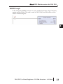
Please include the Manual Number and the Manual Issue, both shown
below, when communicating with Technical Support regarding this
publication.
Manual Number:
DL05-DS6IBOX-S (Supplement to D0-USER-M)
Issue:
Original Edition
Issue Date:
7/14
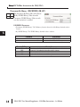
Publication History
4
Issue
Date
1st Edition
7/14
Description of Changes
Original Edition
DL05 PLC User Manual Supplement - DS6 IBox Instructions - 1st Edition
DirectSOFT6 IBox Instructions for DL05 PLCs
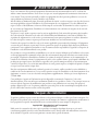
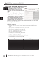
Overview
The Ibox Instructions listed in this supplement are in addition to the Standard RLL and
IBOX Instructions found in Chapter 5 of the DL05 User Manual. These new instructions are
available when using DirectSOFT6 to program your DL05 PLC. For more information on
DirectSOFT6 and to download our Free version, please visit our Web site at:
www.automationdirect.com
Analog Helper IBoxes
Instruction
Filter Over Time - BCD Double (FILTERD)
Hi/Lo Alarm - Binary Double (HILOALBD)
Hi/Lo Alarm - BCD Double (HILOALD)
Memory IBoxes
Instruction
Move Range of V Using MOV (MOVRANGE)
Move Range of V Using FOR/NEXT (MOVEFOR)
Ibox #
Page
IB-425
IB-404
IB-424
06
08
10
Ibox #
Page
IB-203
IB-204
12
14
Ibox #
Page
IB-504
IB-507
IB-526
IB-527
IB-505
IB-524
IB-525
IB-509
16
18
20
22
24
26
28
30
Ibox #
Page
IB-742
IB-743
32
36
Ibox #
Page
IB-1015
IB-1016
IB-1017
IB-1018
IB-1019
IB-1020
38
40
42
44
46
48
Math IBoxes
Instruction
Absolute Value - Binary (ABSBIN)
Decrement By Binary (DECBYBIN)
Decrement By BCD (DECBYBCD)
Decrement By BCD Double (DECBYBCDD)
Increment By Binary (INCBYBIN)
Increment By BCD (INCBYBCD)
Increment By BCD Double (INCBYBCDD)
Scale Value - Unsigned Binary (SCALEB)
Communication IBoxes
Instruction
ECOM100 Read PEERLINK Status (ECRDPL)
ECOM100 Write PEERLINK Pause (ECWRPLPA)
Counter I/O IBoxes
Instruction
CTRIO Edit Level (CTRELVL)
CTRIO Register Read (CTRRGRD)
CTRIO Register Write (CTRRGWR)
CTRIO Velocity Mode 2 (CTRVEL2)
CTRIO Run to Limit Mode 2 (CTRRTLM2)
CTRIO Run to Position Mode 2 (CTRRTPM2)
DL05 PLC User Manual Supplement - DS6 IBox Instructions - 1st Edition
5
1
2
3
4
S
6
7
8
9
10
11
12
13
14
A
B
C
D
DirectSOFT6 IBox Instructions for DL05 PLCs
Filter Over Time - BCD Double (FILTERD) (IB-425)
1
2
3
4
S
6
7
8
9
10
11
12
13
14
A
B
C
D
DS6
Used
HPP
N/A
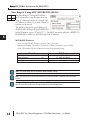
The Filter Over Time - BCD Double IBox
performs a first-order filter on the specified 32bit Raw BCD Data value using the specified
time interval.
A first order is essentially a lag function, so the
FDC (Filter Divisor Constant) represents the
amount of desired lag. A Value of 1 represents
no lag, a value of 100 represents the maximum
amount of lag.
The formula used is:
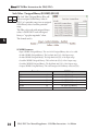
FILTERD Parameters
• Filter Freq Timer: The PLC Timer used to generate the calculation time intervals.
• Filter Freq Time (0.01 sec): The timer preset value in tens of milliseconds (BCD) which specifies
the rate at which the calculations take place.
• Raw Data (BCD Double): The first V-Memory of two successive V-Memory locations where the
32-bit BCD input data value is stored.
• Filter Divisor: This value specifies the amount of desired lag (BCD).
• Filter Value (BCD Double): The first V-Memory of two successive V-Memory locations where the
new 32-bit filtered output value will be stored.
Parameter
Filter Freq Timer . . . . . . . . . . . . . . . . . . . . . . . . T
Filter Freq Time . . . . . . . . . . . . . . . . . . . . . . . V, K
Raw Data . . . . . . . . . . . . . . . . . . . . . . . . . . . . . . V
Filter Divisor . . . . . . . . . . . . . . . . . . . . . . . . . . V, K
Filter Value . . . . . . . . . . . . . . . . . . . . . . . . . . . . . V
6
DL05 Range
T0-T377
K0-9999, All V Memory
All V Memory
K1-100, All V Memory
All V Memory
DL05 PLC User Manual Supplement - DS6 IBox Instructions - 1st Edition
DirectSOFT6 IBox Instructions for DL05 PLCs
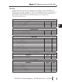
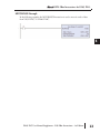
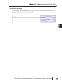
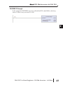
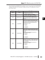
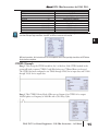
FILTERD Example
In the following example, the FILTERD instruction is used to filter a double word BCD
value that is in V2054-V2055. Timer(T1) is set to 0.5 sec, the rate at which the filter
calculation will be performed. The filter constant is set to 2. A larger value will increase the
smoothing effect of the filter. A value of 1 results in no filtering. The filtered value will be
placed in V2056-V2057.
DL05 PLC User Manual Supplement - DS6 IBox Instructions - 1st Edition
1
2
3
4
S
6
7
8
9
10
11
12
13
14
A
B
C
D
7
DirectSOFT6 IBox Instructions for DL05 PLCs
Hi/Lo Alarm - Binary Double (HILOALBD) (IB-404)
1
2
3
4
S
6
7
8
9
10
11
12
13
14
A
B
C
D
DS6
Used
HPP
N/A
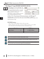
The Hi/Lo Alarm - Binary Double IBox
monitors the 32-bit binary (decimal) value that
is stored in two successive V-Memory locations
and sets the appropriate alarm states based on
the alarm limit values.
When you enter the alarm limit values you must
ensure that the High-High limit ≥ the High limit
≥ the Low limit ≥ the Low-Low limit.
The alarm limits are inclusive. For example, the
High and High-High alarm bits will be ON
when the Monitoring Value ≥ High-High limit
and the Monitoring Value ≥ High limit. The
Low and Low-Low alarm bits will be ON when the Monitoring Value ≤ Low limit and the
Monitoring Value ≤ Low-Low limit.
HILOALBD Parameters
• Monitoring Value (Binary Double): The first V-Memory location of the 32-bit binary (decimal)
value to monitor.
• High-High Limit: The High-High alarm limit value (binary double).
• High-High Alarm: The High-High alarm output BIT.
• High Limit: The High alarm limit value (binary double).
• High Alarm: The High alarm output BIT.
• Low Limit: The Low alarm limit value (binary double).
• Low Alarm: The Low alarm output BIT.
• Low-Low Limit: The Low-Low alarm limit value (binary double).
• Low-Low Alarm: The Low-Low alarm output BIT.
Parameter
Monitoring Value . . . . . . . . . . . . . . . . . . . . . . . V
High-High Limit . . . . . . . . . . . . . . . . . . . . . . . V, K
High-High Alarm . . . . . . . . . . . X, Y, C, GX,GY, B
High Limit . . . . . . . . . . . . . . . . . . . . . . . . . . . V, K
High Alarm . . . . . . . . . . . . . . . . X, Y, C, GX,GY, B
Low Limit . . . . . . . . . . . . . . . . . . . . . . . . . . . V, K
Low Alarm . . . . . . . . . . . . . . . . X, Y, C, GX,GY,B
Low-Low Limit . . . . . . . . . . . . . . . . . . . . . . . V, K
Low-Low Alarm. . . . . . . . . . . . . X, Y, C, GX,GY, B
8
DL05 Range
All V Memory
K0-4294967295; All V Memory
All Bit Memory
K0-4294967295; All V Memory
All Bit Memory
K0-4294967295; All V Memory
All Bit Memory
K0-4294967295; All V Memory
All Bit Memory
DL05 PLC User Manual Supplement - DS6 IBox Instructions - 1st Edition
DirectSOFT6 IBox Instructions for DL05 PLCs
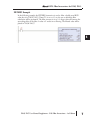
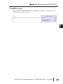
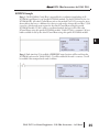
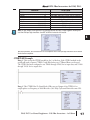
HILOALBD Example
In the following example, the HILOALBD instruction is used to monitor a double word
binary value that is in V2026-V2027. If the value in V2026-V2027 meets/exceeds the high
limit of K80000, C46 will turn ON. If the value continues to increase to meet/exceed the
high-high limit of K90000, C45 will turn ON. Both bits would be ON in this case. The high
and high-high limits and alarms can be set to the same value if one “high” limit or alarm is
desired to be used.
If the value in V2026-V2027 meets or falls below the low limit of K20000, C47 will turn
ON. If the value continues to decrease to meet or fall below the low-low limit of K10000,
C50 will turn ON. Both bits would be ON in this case. The low and low-low limits and
alarms can be set to the same value if one “low” limit or alarm is desired to be used.
DL05 PLC User Manual Supplement - DS6 IBox Instructions - 1st Edition
9
1
2
3
4
S
6
7
8
9
10
11
12
13
14
A
B
C
D
DirectSOFT6 IBox Instructions for DL05 PLCs
Hi/Lo Alarm - BCD Double (HILOALD) (IB-424)
1
2
3
4
S
6
7
8
9
10
11
12
13
14
A
B
C
D
DS6
Used
HPP
N/A
The Hi/Lo Alarm - BCD Double IBox monitors
the 32-bit BCD value that is stored in two
successive V-Memory locations and sets the
appropriate alarm states based on the alarm limit
values.
When you enter the alarm limit values you must
ensure that the High-High limit ≥ the High limit
≥ the Low limit ≥ the Low-Low limit.
The alarm limits are inclusive. For example, the
High and High-High alarm bits will be ON
when the Monitoring Value ≥ High-High limit
and the Monitoring Value ≥ High limit. The
Low and Low-Low alarm bits will be ON when the Monitoring Value ≤ Low limit and the
Monitoring Value ≤ Low-Low limit.
HILOALD Parameters
• Monitoring Value (BCD Double): The first V-Memory location of the 32-bit BCD value to
monitor.
• High-High Limit: The High-High alarm limit value (BCD double).
• High-High Alarm: The High-High alarm output BIT.
• High Limit: The High alarm limit value (BCD double).
• High Alarm: The High alarm output BIT.
• Low Limit: The Low alarm limit value (BCD double).
• Low Alarm: The Low alarm output BIT.
• Low-Low Limit: The Low-Low alarm limit value (BCD double).
• Low-Low Alarm: The Low-Low alarm output BIT.
Parameter
Monitoring Value . . . . . . . . . . . . . . . . . . . . . . . V
High-High Limit . . . . . . . . . . . . . . . . . . . . . . . V, K
High-High Alarm . . . . . . . . . . . X, Y, C, GX,GY, B
High Limit . . . . . . . . . . . . . . . . . . . . . . . . . . . V, K
High Alarm . . . . . . . . . . . . . . . . X, Y, C, GX,GY, B
Low Limit . . . . . . . . . . . . . . . . . . . . . . . . . . . V, K
Low Alarm . . . . . . . . . . . . . . . . X, Y, C, GX,GY,B
Low-Low Limit . . . . . . . . . . . . . . . . . . . . . . . V, K
Low-Low Alarm. . . . . . . . . . . . . X, Y, C, GX,GY, B
10
DL05 Range
All V Memory
K0-99999999; All V Memory
All Bit Memory
K0-99999999; All V Memory
All Bit Memory
K0-99999999; All V Memory
All Bit Memory
K0-99999999; All V Memory
All Bit Memory
DL05 PLC User Manual Supplement - DS6 IBox Instructions - 1st Edition
DirectSOFT6 IBox Instructions for DL05 PLCs
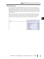
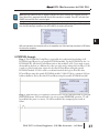
HILOALD Example
In the following example, the HILOALD instruction is used to monitor a double word BCD
value that is in V2026-V2027. If the value in V2026-V2027 meets/exceeds the high limit of
K80000, C41 will turn ON. If the value continues to increase to meet/exceed the high-high
limit of K90000, C40 will turn ON. Both bits would be ON in this case. The high and highhigh limits and alarms can be set to the same value if one “high” limit or alarm is desired to be
used.
If the value in V2026-V2027 meets or falls below the low limit of K20000, C42 will turn
ON. If the value continues to decrease to meet or fall below the low-low limit of K10000,
C43 will turn ON. Both bits would be ON in this case. The low and low-low limits and
alarms can be set to the same value if one “low” limit or alarm is desired to be used.
DL05 PLC User Manual Supplement - DS6 IBox Instructions - 1st Edition
11
1
2
3
4
S
6
7
8
9
10
11
12
13
14
A
B
C
D
DirectSOFT6 IBox Instructions for DL05 PLCs
Move Range of V using MOV (MOVRANGE) (IB-203)
1
2
3
4
S
6
7
8
9
10
11
12
13
14
A
B
C
D
DS6
Used
HPP
N/A
The Move Range of V using MOV will use a
MOV instruction to copy the values from one
range of V-Memory locations to a second range
of V-Memory locations. Up to 4095 V-Memory
locations can be moved.
The MOV instruction has special behavior in
the DL05 when dealing with the FLASH ROM
backed V-Memory regions (V7400-V7577). The MOV instruction will cause a WRITE TO
FLASH ROM in addition to the RAM copy of the V-Memory.
MOVRANGE Parameters
• Start of Source: The first V-Memory location of the source range.
• Number of Elements: The number of consecutive V-Memory locations to process (BCD).
• Start of Destination: The first V-Memory location of the destination range.
Parameter
Start of Source . . . . . . . . . . . . . . . . . . . . . . . . . V
Number of Elements . . . . . . . . . . . . . . . . . . . . V,K
Start of Destination . . . . . . . . . . . . . . . . . . . . . . V
DL05 Range
All V Memory
K1 - 4095, All V Memory
All V Memory
Note: The Source Range and the Destination Range CAN NOT overlap.
Note: If the instruction will be moving double-word values the Number of Elements must be an even
number.
Note: All of the locations will be moved in the same PLC scan, which will cause an increase in the scan
time. Be aware this increase may be large enough to trip with watchdog timer.
12
DL05 PLC User Manual Supplement - DS6 IBox Instructions - 1st Edition
DirectSOFT6 IBox Instructions for DL05 PLCs
MOVRANGE Example
In the following example, the MOVRANGE instruction is used to move 8 words of data
from V2050-V2057 to V2060-V2067.
DL05 PLC User Manual Supplement - DS6 IBox Instructions - 1st Edition
1
2
3
4
S
6
7
8
9
10
11
12
13
14
A
B
C
D
13
DirectSOFT6 IBox Instructions for DL05 PLCs
Move Range of V using FOR/NEXT (MOVEFOR) (IB-204)
1
2
3
4
S
6
7
8
9
10
11
12
13
14
A
B
C
D
DS6
Used
HPP
N/A
The Move Range of V using FOR/NEXT will
use a FOR/NEXT loop to copy the values from
one range of V-Memory locations to a second
range of V-Memory locations. Up to 4095 VMemory locations can be moved.
The DL05 has a range of V-Memory locations
that are backed by ROM-based memory
(V7400 - V7577). This instruction will only move the values to the RAM copy if the
destination range is in this specific range. Use the Move Range of V using MOV
(MOVRANGE) instruction to move the value to both the RAM and ROM copies of this
specific destination range
MOVEFOR Parameters
• Start of Source: The first V-Memory location of the source range.
• Number of Elements: The number of consecutive V-Memory locations to process (BCD).
• Start of Destination: The first V-Memory location of the destination range.
Parameter
Start of Source . . . . . . . . . . . . . . . . . . . . . . . . . V
Number of Elements . . . . . . . . . . . . . . . . . . . . V,K
Start of Destination . . . . . . . . . . . . . . . . . . . . . . V
DL05 Range
All V Memory
K1 - 4095, All V Memory
All V Memory
Note: The Source Range and the Destination Range CAN NOT overlap.
Note: If the instruction will be moving double-word values the Number of Elements must be an even
number.
Note: All of the locations will be moved in the same PLC scan, which will cause an increase in the scan
time. Be aware this increase may be large enough to trip with watchdog timer.
14
DL05 PLC User Manual Supplement - DS6 IBox Instructions - 1st Edition
DirectSOFT6 IBox Instructions for DL05 PLCs
MOVEFOR Example
In the following example, the MOVEFOR instruction is used to move 8 words of data from
V2070-V2077 to V3000-V3007.
DL05 PLC User Manual Supplement - DS6 IBox Instructions - 1st Edition
15
1
2
3
4
S
6
7
8
9
10
11
12
13
14
A
B
C
D
DirectSOFT6 IBox Instructions for DL05 PLCs
Absolute Value - Binary (ABSBIN) (IB-504)
1
2
3
4
S
6
7
8
9
10
11
12
13
14
A
B
C
D
DS6
Used
HPP
N/A
The Absolute Value - Binary IBox returns the
absolute value of the number Binary (decimal)
found in the specified V-Memory location. If the
Value is negative, it negates the Value to make it
positive and stores it in Result and turns the Is
Negative bit ON. Otherwise, it returns the Value
unchanged and the Is Negative bit is OFF.
For example:
If V2046 = 31415 the result in V2052/V2053 would be 31415, and the Is Negative bit (C40)
would be OFF.
If V2046 = -31415 the result in V2052/V2053 would be 31415, and the Is Negative bit
(C40) would be ON.
ABSBIN Parameters
• Value (WORD Binary): The V-Memory location where the 16-bit Binary (decimal) value is located.
• Result (DWORD Binary): The first V-Memory location where the 32-bit Binary (decimal) absolute
value will be stored.
• Is Negative: If Value (WORD binary) is negative this bit will be ON. If Value (WORD binary) is
not negative (e.g. zero or positive) this bit will be OFF.
Parameter
Value . . . . . . . . . . . . . . . . . . . . . . . . . . . . . . . . . V
Result . . . . . . . . . . . . . . . . . . . . . . . . . . . . . . . . V
Is Negative . . . . . . . . . . . . . . . . . . X,Y,C,GX,GY,B
16
DL05 Range
All V Memory
All V Memory
All Bit Memory
DL05 PLC User Manual Supplement - DS6 IBox Instructions - 1st Edition
DirectSOFT6 IBox Instructions for DL05 PLCs
ABSBIN Example
In this example the ABSBIN instruction is used to calculate the absolute value of the binary
number stored in V2046. The result is stored in V2052-V2053 and C40 will be set if the
value of V2046 was negative.
DL05 PLC User Manual Supplement - DS6 IBox Instructions - 1st Edition
17
1
2
3
4
S
6
7
8
9
10
11
12
13
14
A
B
C
D
DirectSOFT6 IBox Instructions for DL05 PLCs
Decrement By Binary (DECBYBIN) (IB-507)
1
2
3
4
S
6
7
8
9
10
11
12
13
14
A
B
C
D
DS6
Used
HPP
N/A
The Decrement By Binary IBox will subtract
the By (WORD Binary) Value from the
Decrement (WORD Binary) Value on each
scan the instruction is enabled.
DECBYBIN Parameters
• Decrement (WORD Binary): The V-Memory location where the 16-bit Binary (decimal) value is
located.
• By (WORD Binary): The WORD Binary (decimal) value to subtract.
Parameter
Decrement . . . . . . . . . . . . . . . . . . . . . . . . . . . . . V
By . . . . . . . . . . . . . . . . . . . . . . . . . . . . . . . . . . V,K
18
DL05 Range
All V Memory
K0 - 65535, All V Memory
Discrete Bit Flags
Description
SP63
SP64
SP65
SP70
On when the result of the instruction causes the value in the accumulator to be zero.
On when the 16- bit subtraction instruction results in a borrow
On when the 32-bit subtraction instruction results in a borrow
On anytime the value in the accumulator is negative.
DL05 PLC User Manual Supplement - DS6 IBox Instructions - 1st Edition
DirectSOFT6 IBox Instructions for DL05 PLCs
DECBYBIN Example
In this example the DECBYBIN instruction will subtract the value K100 from the binary
value in V2112 on every scan that C0 is ON.
DL05 PLC User Manual Supplement - DS6 IBox Instructions - 1st Edition
1
2
3
4
S
6
7
8
9
10
11
12
13
14
A
B
C
D
19
DirectSOFT6 IBox Instructions for DL05 PLCs
Decrement By BCD (DECBYBCD) (IB-526)
1
2
3
4
S
6
7
8
9
10
11
12
13
14
A
B
C
D
DS6
Used
HPP
N/A
The Decrement By BCD IBox will subtract the
By (WORD BCD) Value from the Decrement
(WORD BCD) Value on each scan the
instruction is enabled.
DECBYBCD Parameters
• Decrement (WORD BCD): The V-Memory location where the 16-bit BCD value is located.
• By (WORD BCD): The WORD BCD value to subtract.
Parameter
Decrement . . . . . . . . . . . . . . . . . . . . . . . . . . . . . V
By . . . . . . . . . . . . . . . . . . . . . . . . . . . . . . . . . . V,K
20
DL05 Range
All V Memory
K0 - 9999, All V Memory
Discrete Bit Flags
Description
SP63
SP64
SP65
SP70
SP75
On when the result of the instruction causes the value in the accumulator to be zero.
On when the 16- bit subtraction instruction results in a borrow
On when the 32-bit subtraction instruction results in a borrow
On anytime the value in the accumulator is negative.
On when a BCD instruction is executed and a NON–BCD number was encountered.
DL05 PLC User Manual Supplement - DS6 IBox Instructions - 1st Edition
DirectSOFT6 IBox Instructions for DL05 PLCs
DECBYBCD Example
In this example the DECBYBCD instruction will subtract the BCD value K9900 from the
BCD value in V2116 on every scan that C0 is ON.
DL05 PLC User Manual Supplement - DS6 IBox Instructions - 1st Edition
1
2
3
4
S
6
7
8
9
10
11
12
13
14
A
B
C
D
21
DirectSOFT6 IBox Instructions for DL05 PLCs
Decrement By BCD Double (DECBYBCDD) (IB-527)
1
2
3
4
S
6
7
8
9
10
11
12
13
14
A
B
C
D
DS6
Used
HPP
N/A
The Decrement By BCD Double IBox will
subtract the By (DWORD BCD) Value from
the Decrement (DWORD BCD) Value on
each scan the instruction is enabled.
DECBYBCDD Parameters
• Decrement (DWORD BCD): The V-Memory location where the 32-bit BCD value is located.
• By (DWORD BCD): The DWORD BCD value to subtract.
Parameter
Decrement . . . . . . . . . . . . . . . . . . . . . . . . . . . . . V
By . . . . . . . . . . . . . . . . . . . . . . . . . . . . . . . . . . V,K
22
DL05 Range
All V Memory
K0 - 99999999, All V Memory
Discrete Bit Flags
Description
SP63
SP64
SP65
SP70
SP75
On when the result of the instruction causes the value in the accumulator to be zero.
On when the 16- bit subtraction instruction results in a borrow
On when the 32-bit subtraction instruction results in a borrow
On anytime the value in the accumulator is negative.
On when a BCD instruction is executed and a NON–BCD number was encountered.
DL05 PLC User Manual Supplement - DS6 IBox Instructions - 1st Edition
DirectSOFT6 IBox Instructions for DL05 PLCs
DECBYBCDD Example
In this example the DECBYBCDD instruction will subtract the BCD value K99009900
from the double word BCD value in V2120-V2121 on every scan that C0 is ON.
DL05 PLC User Manual Supplement - DS6 IBox Instructions - 1st Edition
1
2
3
4
S
6
7
8
9
10
11
12
13
14
A
B
C
D
23
DirectSOFT6 IBox Instructions for DL05 PLCs
Increment By Binary (INCBYBIN) (IB-505)
1
2
3
4
S
6
7
8
9
10
11
12
13
14
A
B
C
D
DS6
Used
HPP
N/A
The Increment By Binary IBox will add the By
(WORD Binary) Value to the Increment
(WORD Binary) Value on each scan the
instruction is enabled.
INCBYBIN Parameters
• Increment (WORD Binary): The V-Memory location where the 16-bit Binary (decimal) value is
located.
• By (WORD Binary): The WORD Binary (decimal) value to add.
Parameter
Increment . . . . . . . . . . . . . . . . . . . . . . . . . . . . . V
By . . . . . . . . . . . . . . . . . . . . . . . . . . . . . . . . . . V,K
24
DL05 Range
All V Memory
K0 - 65535, All V Memory
Discrete Bit Flags
Description
SP63
SP66
SP67
SP70
SP73
On when the result of the instruction causes the value in the accumulator to be zero.
On when the 16-bit addition instruction results in a carry.
On when the 32-bit addition instruction results in a carry.
On anytime the value in the accumulator is negative.
On when a signed addition or subtraction results in an incorrect sign bit.
DL05 PLC User Manual Supplement - DS6 IBox Instructions - 1st Edition
DirectSOFT6 IBox Instructions for DL05 PLCs
INCBYBIN Example
In this example the INCBYBIN instruction will add the value K10 to the binary value in
V2100 on every scan that C0 is ON.
DL05 PLC User Manual Supplement - DS6 IBox Instructions - 1st Edition
1
2
3
4
S
6
7
8
9
10
11
12
13
14
A
B
C
D
25
DirectSOFT6 IBox Instructions for DL05 PLCs
Increment By BCD (INCBYBCD) (IB-524)
1
2
3
4
S
6
7
8
9
10
11
12
13
14
A
B
C
D
DS6
Used
HPP
N/A
The Increment By BCD IBox will add the By
(WORD BCD) Value to the Increment
(WORD BCD) Value on each scan the
instruction is enabled.
INCBYBCD Parameters
• Increment (WORD BCD): The V-Memory location where the 16-bit BCD value is located.
• By (WORD BCD): The WORD BCD value to add.
Parameter
Increment . . . . . . . . . . . . . . . . . . . . . . . . . . . . . V
By . . . . . . . . . . . . . . . . . . . . . . . . . . . . . . . . . . V,K
26
DL05 Range
All V Memory
K0 - 9999, All V Memory
Discrete Bit Flags
Description
SP63
SP66
SP67
SP70
SP73
SP75
On when the result of the instruction causes the value in the accumulator to be zero.
On when the 16-bit addition instruction results in a carry.
On when the 32-bit addition instruction results in a carry.
On anytime the value in the accumulator is negative.
On when a signed addition or subtraction results in an incorrect sign bit.
On when a BCD instruction is executed and a NON–BCD number was encountered.
DL05 PLC User Manual Supplement - DS6 IBox Instructions - 1st Edition
DirectSOFT6 IBox Instructions for DL05 PLCs
INCBYBCD Example
In this example the INCBYBCD instruction will add the BCD value K9999 to the binary
value in V2106 on every scan that C0 is ON.
DL05 PLC User Manual Supplement - DS6 IBox Instructions - 1st Edition
1
2
3
4
S
6
7
8
9
10
11
12
13
14
A
B
C
D
27
DirectSOFT6 IBox Instructions for DL05 PLCs
Increment By BCD Double (INCBYBCDD) (IB-525)
1
2
3
4
S
6
7
8
9
10
11
12
13
14
A
B
C
D
DS6
Used
HPP
N/A
The Increment By BCD Double IBox will add
the By (DWORD BCD) Value to the
Increment (DWORD BCD) Value on each
scan the instruction is enabled.
INCBYBCDD Parameters
• Increment (DWORD BCD): The V-Memory location where the 32-bit BCD value is located.
• By (DWORD BCD): The DWORD BCD value to add.
Parameter
Increment . . . . . . . . . . . . . . . . . . . . . . . . . . . . . V
By . . . . . . . . . . . . . . . . . . . . . . . . . . . . . . . . . . V,K
28
DL05 Range
All V Memory
K0 - 99999999, All V Memory
Discrete Bit Flags
Description
SP63
SP66
SP67
SP70
SP73
SP75
On when the result of the instruction causes the value in the accumulator to be zero.
On when the 16-bit addition instruction results in a carry.
On when the 32-bit addition instruction results in a carry.
On anytime the value in the accumulator is negative.
On when a signed addition or subtraction results in an incorrect sign bit.
On when a BCD instruction is executed and a NON–BCD number was encountered.
DL05 PLC User Manual Supplement - DS6 IBox Instructions - 1st Edition
DirectSOFT6 IBox Instructions for DL05 PLCs
INCBYBCDD Example
In this example the INCBYBCDD instruction will add the BCD value K99999999 to the
BCD value in V2110-V2111 on every scan that C0 is ON.
DL05 PLC User Manual Supplement - DS6 IBox Instructions - 1st Edition
1
2
3
4
S
6
7
8
9
10
11
12
13
14
A
B
C
D
29
DirectSOFT6 IBox Instructions for DL05 PLCs
Scale Value - Unsigned Binary (SCALEB) (IB-509)
1
2
3
4
S
6
7
8
9
10
11
12
13
14
A
B
C
D
DS6
Used
HPP
N/A
The Scale Value Unsigned Binary IBox will
scale an unsigned 16-bit Binary value (065535) of a particular range into an unsigned
16-bit Binary value of another particular
range.
This IBox only works with unsigned binary
values, it DOES NOT work with signed
binary or "sign plus magnitude" values.
The formula used is:
SCALEB Parameters
• Input (WORD Unsigned Binary): The raw 16-bit Unsigned Binary value to be scaled.
• In Min (WORD Unsigned Binary): The low limit (0-65535) of the Input range.
• In Max (WORD Unsigned Binary): The high limit (0-65535) of the Input range.
• Out Min (WORD Unsigned Binary): The low limit (0-65535) of the Output range.
• Out Max (WORD Unsigned Binary): The high limit (0-65535) of the Output range.
• Output (WORD Unsigned Binary): The scaled unsigned 16-bit Binary value (0-65535).
Parameter
30
DL05 Range
Input . . . . . . . . . . . . . . . . . . . . . . . . . . . . . . . . . V
All V Memory
In Min . . . . . . . . . . . . . . . . . . . . . . . . . . . . . . . V,K
K0 - 65535, All V Memory
In Max . . . . . . . . . . . . . . . . . . . . . . . . . . . . . . V,K
K0 - 65535, All V Memory
Out Min . . . . . . . . . . . . . . . . . . . . . . . . . . . . . . V,K
K0 - 65535, All V Memory
Out Max . . . . . . . . . . . . . . . . . . . . . . . . . . . . . V,K
Output . . . . . . . . . . . . . . . . . . . . . . . . . . . . . . . . V
K0 - 65535, All V Memory
All User V Memory
DL05 PLC User Manual Supplement - DS6 IBox Instructions - 1st Edition
DirectSOFT6 IBox Instructions for DL05 PLCs
SCALEB Example
In this SCALEB example a single word unsigned binary value from a 12 bit analog card in
V2000 is being scaled from the 0 – 4095 raw value to 0 – 100 engineering units and the
result is being stored in V2100 as a single word unsigned binary value. For example, if V2000
has a value of 2048 then the resulting value stored in V2100 is 50.
DL05 PLC User Manual Supplement - DS6 IBox Instructions - 1st Edition
31
1
2
3
4
S
6
7
8
9
10
11
12
13
14
A
B
C
D
DirectSOFT6 IBox Instructions for DL05 PLCs
ECOM100 Read PEERLINK Status (ECRDPL) (IB-742)
1
2
3
4
S
6
7
8
9
10
11
12
13
14
A
B
C
D
DS6
Used
HPP
N/A
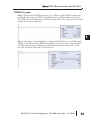
The ECOM100 Read PEERLINK Status
IBox will read the PEERLINK operation's
runtime status information from an
ECOM100 that is configured to be part of a
PEERLINK network. This IBox will return
6 registers that contain information about
current PEERLINK status and
configuration.
It references the ECOM100 # of the
ECOM100 Config IBox that is controlling
the ECOM100 module in a specific slot. The ECOM100 Config contains built-in
interlocking logic that is used to synchronize the processing of this IBox with all of the other
IBoxes in the ladder program that are being processed by the same ECOM100.
A PEERLINK network is a data sharing network that consists of any number of
DirectLOGIC PLC and/or Do-more PLC systems using ECOM100 modules and/or the Domore PLC's onboard Ethernet port. Each member of the data sharing network can receive
data from the other members on the data sharing network by "subscribing to" them, or send
data to the other members of the network by electing to "publish" one or more blocks of
PEERLINK memory.
When PEERLINK is configured in an ECOM100 the user specifies a section of V-Memory
that is allocated for exclusive use by the PEERLINK operation. This memory contains 256
locations. These 256 locations are divided into 16 blocks. Each of these 16 data blocks
consists of 16-Bit registers. Theses blocks provide the local storage for the data that is sent and
received over the data-sharing network.
PEERLINK uses the verbs 'publishing' and 'subscribing' to describe how data is exchanged
with ECOM100s on the data sharing network. Publishing is analogous to sending data, and
is done only if the PEERLINK configuration is set to 'publish' one or more of its own data
blocks. If so configured, the ECOM100 will broadcast a packet that contains all of the data
from the V-Memory blocks. There are sixteen unique data blocks, and each data block can
only be published by one ECOM100 or Do-more PLC. This means there can be a maximum
of sixteen unique ECOMs configured to publish blocks of data. A single ECOM100 can be
configured so that it publishes none of the blocks, one block, some of the blocks, or even all
16 of the blocks.
Subscribing is analogous to receiving data, and is accomplished by 'subscribing to' the data
blocks of all the other controllers on the data sharing network. Once PEERLINK is enabled,
it listens to the network for PEERLINK broadcasts messages from other ECOM100s or Domore PLCs. When it receives one, it examines the data from that packet, and for blocks that
are configured as "Subscribe To", it stores that data in the controller's local V-Memory in the
appropriate block.
The PEERLINK network uses TCP/IP broadcast packets to publish the blocks of data to the
network. One caveat with the use of broadcast packets is that it limits the scope of the shared
data network to the local broadcast domain.
32
DL05 PLC User Manual Supplement - DS6 IBox Instructions - 1st Edition
DirectSOFT6 IBox Instructions for DL05 PLCs
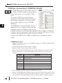
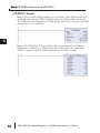
The ECOM100 Read PEERLINK Status IBox retrieves 6 status values from the ECOM100
and places those values in 6 consecutive V-Memory locations. The definitions of those 6
status values follows:
Number
Name
Word 1
Paused
Word 2
PEERLINK Enabled
Word 3
PEERLINK Address
Word 4
Word 5
Word 6
Description
1 = PEERLINK processing is Paused in this ECOM100
0 = PEERLINK processing is Active
1 = PEERLINK is Enabled in this ECOM100
0 = PEERLINK is NOT Enabled in this ECOM100
The first of the 256 V-Memory locations that the
PEERLINK operation uses for storing the data that is
sent and received through the Publish and Subscribe
operations
Ignored Blocks
Indicates which of the 16 PEERLINK blocks are being
ignored by this ECOM100. If the bit is ON the block is
being ignored, if the bit is OFF the block is NOT ignored.
Each of the 16 bits in this Word corresponds to a
PEERLINK block as follows:
Bit 0 = Block 0
Bit 1 = Block 1
...
Bit 14 = Block 14
Bit 15 = Block 15
Published Blocks
Indicates which of the 16 PEERLINK blocks are being
published by this ECOM100. If the bit is ON the block is
being published, if the bit is OFF the block is NOT being
published.
Each of the 16 bits in this Word corresponds to a
PEERLINK block as follows:
Bit 0 = Block 0
Bit 1 = Block 1
...
Bit 14 = Block 14
Bit 15 = Block 15
Subscribed Blocks
Indicates which of the 16 PEERLINK blocks this
ECOM100 is subscribing to. If the bit is ON the block is
being subscribed to, if the bit is OFF the block is NOT
being subscribed to.
Each of the 16 bits in this Word corresponds to a
PEERLINK block as follows:
Bit 0 = Block 0
Bit 1 = Block 1
...
Bit 14 = Block 14
Bit 15 = Block 15
DL05 PLC User Manual Supplement - DS6 IBox Instructions - 1st Edition
33
1
2
3
4
S
6
7
8
9
10
11
12
13
14
A
B
C
D
DirectSOFT6 IBox Instructions for DL05 PLCs
ECRDPL Parameters
• ECOM100#: This is a logical number associated with this specific ECOM100 module in the
specified slot. All other ECxxxx IBoxes that need to reference this ECOM100 module must
reference this logical number.
1
2
3
4
S
6
7
8
9
10
11
12
13
14
A
B
C
D
• Workspace: A V-Memory register that is used internally by this IBox. It must not be used by any
other instructions in the PLC.
• Success: This BIT will be ON if the ECRDPL succeeds and OFF if the ECRDPL fails.
• Error: This BIT will be OFF if the ECRDPL succeeds and ON if the ECRDPL fails.
• PEERLINK Status (6 Words): The first of the 6 consecutive V-Memory registers where the
PEERLINK Status values will be stored.
Parameter
ECOM100# . . . . . . . . . . . . . . . . . . . . . . . . . . . . K
Workspace . . . . . . . . . . . . . . . . . . . . . . . . . . . . V
Success . . . . . . . . . . . . . . . . . . . . X,Y,C,GX,GY,B
Error . . . . . . . . . . . . . . . . . . . . . . . X,Y,C,GX,GY,B
PEERLINK Status . . . . . . . . . . . . . . . . . . . . . . . V
DL05 Range
K0-255
All User V Memory
All Bit Memory
All Bit Memory
All User V Memory
Note: When the ECRDPL IBox is allowed to execute, the Success and Error BITs are both set to OFF. One of
these Bits is guaranteed to be ON after the IBox execution is complete. These BITs will retain their ON/OFF
value until the IBox is executed again.
Note: The gray triangle at the right end of an input leg indicates the input is edge triggered. Meaning that
each time the input logic transitions from OFF to ON this instruction will execute.
With each execution, this instruction will run to completion even if the input logic transitions to OFF before
the instruction completes.
34
DL05 PLC User Manual Supplement - DS6 IBox Instructions - 1st Edition
DirectSOFT6 IBox Instructions for DL05 PLCs
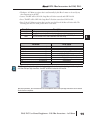
ECRDPL Example
Rung 1: The ECOM100 Config IBox is responsible for coordination/interlocking of all
ECOM100 type IBoxes for one specific ECOM100 module. Tag the ECOM100 in slot 3 as
ECOM100# K1. All other ECxxxx IBoxes refer to this module # as K1. If you need to move
the module in the base to a different slot, then you only need to change this one IBox. V1501
is used as a global result status register for the other ECxxxx IBoxes using this specific
ECOM100 module. V1502 is used to coordinate/interlock the logic in all of the other
ECxxxx IBoxes using this specific ECOM100 module. V1400-V1500 is a common 130 byte
buffer available for use by the other ECxxxx IBoxes using this specific ECOM100 module.
Rung 2: Each time that C0 is enabled, 6 PEERLINK status locations will be read from the
ECOM100 and stored in V2000-V2005. C1 will be enabled if the read is a success, C2 will
be enabled if the attempted read results in failure.
DL05 PLC User Manual Supplement - DS6 IBox Instructions - 1st Edition
35
1
2
3
4
S
6
7
8
9
10
11
12
13
14
A
B
C
D
DirectSOFT6 IBox Instructions for DL05 PLCs
ECOM100 Write PEERLINK Pause (ECWRPLPA) (IB-743)
1
2
3
4
S
6
7
8
9
10
11
12
13
14
A
B
C
D
DS6
Used
HPP
N/A
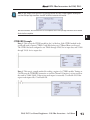
The ECOM100 Write PEERLINK Pause
IBox will Enable and/or Disable the
PEERLINK processing in the specified
ECOM100.
It references the ECOM100 # of the
ECOM100 Config IBox that is controlling
the ECOM100 module in a specific slot.
The ECOM100 Config contains built-in
interlocking logic that is used to synchronize
the processing of this IBox with all of the
other IBoxes in the ladder program that are being processed by the same ECOM100.
ECWRPLPA Parameters
• ECOM100#: This is a logical number associated with this specific ECOM100 module in the
specified slot. All other ECxxxx IBoxes that need to reference this ECOM100 module must
reference this logical number.
• Workspace: A V-Memory register that is used internally by this IBox. It must not be used by any
other instructions in the PLC.
• Success: This BIT will be ON if the Write operation succeeds and OFF if the Write operation fails.
• Error: This BIT will be OFF if the Write operation succeeds and ON if the Write operation fails.
• Error Code: A V-Memory register that stores the Return Code from the ECOM100 if the Write
operation fails. It must not be used by any other instructions in the PLC.
The possible Error Return Codes are:
0 = No Error
126 = Write Protect Error - the ECOM100 is configured to use DIP Switch 5 to write
protect the ECOM100, and DIP 5 is ON
• PEERLINK Pause: The value to write, either a constant or a V-Memory location that contains the
following values:
0 = Allow PEERLINK operation
1 = Pause PEERLINK operation
Parameter
ECOM100# . . . . . . . . . . . . . . . . . . . . . . . . . . . . K
Workspace . . . . . . . . . . . . . . . . . . . . . . . . . . . . V
Success . . . . . . . . . . . . . . . . . . . . X,Y,C,GX,GY,B
Error . . . . . . . . . . . . . . . . . . . . . . . X,Y,C,GX,GY,B
Error Code . . . . . . . . . . . . . . . . . . X,Y,C,GX,GY,B
PEERLINK Pause . . . . . . . . . . . . . . . . . . . . . . V,K
36
DL05 Range
K0-255
All User V Memory
All Bit Memory
All Bit Memory
All Bit Memory
K0-1, All User V Memory
DL05 PLC User Manual Supplement - DS6 IBox Instructions - 1st Edition
DirectSOFT6 IBox Instructions for DL05 PLCs
Note: When the ECWRPLPA IBox is allowed to execute, the Success and Error BITs are both set to OFF.
One of these Bits is guaranteed to be ON after the IBox execution is complete. These BITs will retain their
ON/OFF value until the IBox is executed again.
Note:The gray triangle at the right end of an input leg indicates the input is edge triggered. Meaning that
each time the input logic transitions from OFF to ON this instruction will execute.
With each execution, this instruction will run to completion even if the input logic transitions to OFF before
the instruction completes.
ECWRPLPA Example
Rung 1: The ECOM100 Config IBox is responsible for coordination/interlocking of all
ECOM100 type IBoxes for one specific ECOM100 module. Tag the ECOM100 in slot 3 as
ECOM100# K1. All other ECxxxx IBoxes refer to this module # as K1. If you need to move
the module in the base to a different slot, then you only need to change this one IBox. V1501
is used as a global result status register for the other ECxxxx IBoxes using this specific
ECOM100 module. V1502 is used to coordinate/interlock the logic in all of the other
ECxxxx IBoxes using this specific ECOM100 module. V1400-V1500 is a common 130 byte
buffer available for use by the other ECxxxx IBoxes using this specific ECOM100 module.
Rung 2: Each time that C0 is enabled, K1 will be sent to the ECOM100 module to pause the
PEERLINK feature. A K0 would need to be sent to resume PEERLINK operation. C1 will
be enabled if the pause is a success, C2 will be enabled if the attempted pause results in
failure.
DL05 PLC User Manual Supplement - DS6 IBox Instructions - 1st Edition
37
1
2
3
4
S
6
7
8
9
10
11
12
13
14
A
B
C
D
DirectSOFT6 IBox Instructions for DL05 PLCs
CTRIO Edit Level (CTRELVL) (IB-1015)
1
2
3
4
S
6
7
8
9
10
11
12
13
14
A
B
C
D
DS6
Used
HPP
N/A
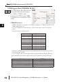
The CTRIO Edit Level IBox will configure the
Level Mode behavior for a Discrete Output of a
CTRIO module.
It references the CTRIO # in the CTRIO
Config IBox that is controlling the CTRIO
module.
CTRELVL Parameters
• CTRIO#: This number corresponds to the
CTRIO # specified in the CTRIO Config IBox
for the CTRIO module being used.
• Output #: Identifies which CTRIO Output to
configure.
• Function (selectable option): ON when greater than Level Rate Setting/ON when less than Level
Rate Setting/OFF when greater than Level Rate Setting/OFF when less than Level Rate Setting.
• Level: The DWORD count value at which the Function above will be active (decimal).
• Deadband (Tenths of %): The value above and below the Level at which the Function will be active
(BCD).
• Workspace: A V-Memory register that is used internally by this IBox. It must not be used by any
other instructions in the PLC.
• Success: This BIT will be ON if the Edit Level succeeds and OFF if the Edit Level fails.
• Error: This BIT will be OFF if the Edit Level succeeds and ON if the Edit Level fails.
Parameter
CTRIO# . . . . . . . . . . . . . . . . . . . . . . . . . . . . . . . K
Output# . . . . . . . . . . . . . . . . . . . . . . . . . . . . . . K
Level . . . . . . . . . . . . . . . . . . . . . . . . . . . . . . . V,K
Deadband# . . . . . . . . . . . . . . . . . . . . . . . . . . V,K
Workspace . . . . . . . . . . . . . . . . . . . . . . . . . . . . V
Success . . . . . . . . . . . . . . . . . . . . X,Y,C,GX,GY,B
Error . . . . . . . . . . . . . . . . . . . . . . . X,Y,C,GX,GY,B
DL05 Range
K0-255
K0-3
K0-2147483647, All User V Memory
K0-1000, All User V Memory
All User V Memory
All Bit Memory
All Bit Memory
Note:The gray triangle at the right end of an input leg indicates the input is edge triggered. Meaning that
each time the input logic transitions from OFF to ON this instruction will execute.
With each execution, this instruction will run to completion even if the input logic transitions to OFF before
the instruction completes.
38
DL05 PLC User Manual Supplement - DS6 IBox Instructions - 1st Edition
DirectSOFT6 IBox Instructions for DL05 PLCs
CTRELVL Example
Rung 1: This sets up the CTRIO module in slot 2 of the base. Each CTRIO module in the
system will need a separate CTRIO Config IBox before any CTRxxxx IBoxes can be used.
The CTRIO has been configured to use V2000 through V2025 for its input data, and V2100
through V2131 for its output data.
Rung 2: This rung is a sample method for configuring the level behavior of a CTRIO output.
Turning on C0 will cause the CTRELVL instruction to set the first output of the module to
ON when the level setting of K1000 is exceeded. If the level request is successful, C1 will
turn ON. If the level request fails, C2 will turn ON.
DL05 PLC User Manual Supplement - DS6 IBox Instructions - 1st Edition
39
1
2
3
4
S
6
7
8
9
10
11
12
13
14
A
B
C
D
DirectSOFT6 IBox Instructions for DL05 PLCs
CTRIO Register Read (CTRRGRD) (IB-1016)
1
2
3
4
S
6
7
8
9
10
11
12
13
14
A
B
C
D
DS6
Used
HPP
N/A
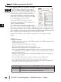
The CTRIO Register Read IBox will
retrieve the value from the specified register
in a CTRIO or CTRIO2 module.
It references the CTRIO # in the CTRIO
Config IBox that is controlling the CTRIO
module.
CTRRGRD Parameters
• CTRIO#: This number corresponds to the
CTRIO # specified in the CTRIO Config IBox for the CTRIO module being used.
• Source Register (selectable option):
0 - Ch1Fn1 Accumulator
1 - Ch1Fn2 Accumulator
10 - Ch2Fn1 Reset Value
11 - Ch2Fn2 Reset Value
2 - Ch2Fn1 Accumulator
12 - Ch1A Filter Time (CTRIO2)
3 - Ch2Fn2 Accumulator
13 - Ch1B Filter Time (CTRIO2)
4 - Out0 Position
14 - Ch1C Filter Time (CTRIO2)
5 - Out1 Position
15 - Ch1D Filter Time (CTRIO2)
6 - Out2 Position
7 - Out3 Position
8 - Ch1Fn1 Reset Value
9 - Ch1Fn2 Reset Value
16 - Ch2A Filter Time (CTRIO2)
17 - Ch2B Filter Time (CTRIO2)
18 - Ch2C Filter Time (CTRIO2)
19 - Ch2D Filter Time (CTRIO2)
• Destination: A DWORD that is used to store the value read from the specified register.
• Workspace: A V-Memory register that is used internally by this IBox. It must not be used by any
other instructions in the PLC.
• Success: This BIT will be ON if the Register Read succeeds and OFF if the Register Read fails.
• Error: This BIT will be OFF if the Register Read succeeds and ON if the Register Read fails.
Parameter
CTRIO# . . . . . . . . . . . . . . . . . . . . . . . . . . . . . . . K
Destination . . . . . . . . . . . . . . . . . . . . . . . . . . . V
Workspace . . . . . . . . . . . . . . . . . . . . . . . . . . . . V
Success . . . . . . . . . . . . . . . . . . . . X,Y,C,GX,GY,B
Error . . . . . . . . . . . . . . . . . . . . . . . X,Y,C,GX,GY,B
40
DL05 Range
K0-255
All User V Memory
All User V Memory
All Bit Memory
All Bit Memory
DL05 PLC User Manual Supplement - DS6 IBox Instructions - 1st Edition
DirectSOFT6 IBox Instructions for DL05 PLCs
Note:The gray triangle at the right end of an input leg indicates the input is edge triggered. Meaning that
each time the input logic transitions from OFF to ON this instruction will execute.
With each execution, this instruction will run to completion even if the input logic transitions to OFF before
the instruction completes.
CTRRGRD Example
Rung 1: This sets up the CTRIO module in slot 2 of the base. Each CTRIO module in the
system will need a separate CTRIO Config IBox before any CTRxxxx IBoxes can be used.
The CTRIO has been configured to use V2000 through V2025 for its input data, and V2100
through V2131 for its output data.
Rung 2: This rung is a sample method for reading a register of a CTRIO module. Turning on
C0 will cause the CTRRGRD instruction to read the Channel 1 Function 1 register and store
the result in V3000-V3001. If the register read request is successful, C1 will turn ON. If the
register read request fails, C2 will turn ON.
DL05 PLC User Manual Supplement - DS6 IBox Instructions - 1st Edition
41
1
2
3
4
S
6
7
8
9
10
11
12
13
14
A
B
C
D
DirectSOFT6 IBox Instructions for DL05 PLCs
CTRIO Register Write (CTRRGWR) (IB-1017)
1
2
3
4
S
6
7
8
9
10
11
12
13
14
A
B
C
D
DS6
Used
HPP
N/A
The CTRIO Register Write IBox will write
the specified value to the selected register
in a CTRIO or CTRIO2 module.
It references the CTRIO # in the CTRIO
Config IBox that is controlling the CTRIO
module.
CTRRGWR Parameters
• CTRIO#: This number corresponds to the CTRIO # specified in the CTRIO Config IBox for the
CTRIO module being used.
• Source: A DWORD that contains the value or a Hex constant value to write to the specified
register.
• Destination Register (selectable option):
0 - Ch1Fn1 Accumulator
1 - Ch1Fn2 Accumulator
10 - Ch2Fn1 Reset Value
11 - Ch2Fn2 Reset Value
2 - Ch2Fn1 Accumulator
12 - Ch1A Filter Time (CTRIO2)
3 - Ch2Fn2 Accumulator
13 - Ch1B Filter Time (CTRIO2)
4 - Out0 Position
14 - Ch1C Filter Time (CTRIO2)
5 - Out1 Position
15 - Ch1D Filter Time (CTRIO2)
6 - Out2 Position
7 - Out3 Position
8 - Ch1Fn1 Reset Value
9 - Ch1Fn2 Reset Value
16 - Ch2A Filter Time (CTRIO2)
17 - Ch2B Filter Time (CTRIO2)
18 - Ch2C Filter Time (CTRIO2)
19 - Ch2D Filter Time (CTRIO2)
• Workspace: A V-Memory register that is used internally by this IBox. It must not be used by any
other instructions in the PLC.
• Success: This BIT will be ON if the Register Write succeeds and OFF if the Register Write fails.
• Error: This BIT will be OFF if the Register Write succeeds and ON if the Register Write fails.
Parameter
CTRIO# . . . . . . . . . . . . . . . . . . . . . . . . . . . . . . . K
Source . . . . . . . . . . . . . . . . . . . . . . . . . . . . . K,V
Workspace . . . . . . . . . . . . . . . . . . . . . . . . . . . . V
Success . . . . . . . . . . . . . . . . . . . . X,Y,C,GX,GY,B
Error . . . . . . . . . . . . . . . . . . . . . . . X,Y,C,GX,GY,B
42
DL05 Range
K0-255
K0-FFFFFFFF, All V Memory
All User V Memory
All Bit Memory
All Bit Memory
DL05 PLC User Manual Supplement - DS6 IBox Instructions - 1st Edition
DirectSOFT6 IBox Instructions for DL05 PLCs
Note:The gray triangle at the right end of an input leg indicates the input is edge triggered. Meaning that
each time the input logic transitions from OFF to ON this instruction will execute.
With each execution, this instruction will run to completion even if the input logic transitions to OFF before
the instruction completes.
CTRRGWR Example
Rung 1: This sets up the CTRIO module in slot 2 of the base. Each CTRIO module in the
system will need a separate CTRIO Config IBox before any CTRxxxx IBoxes can be used.
The CTRIO has been configured to use V2000 through V2025 for its input data, and V2100
through V2131 for its output data.
Rung 2: This rung is a sample method for writing a register of a CTRIO module. Turning on
C0 will cause the CTRRGWR instruction to write the value stored in V3000-V3001 to the
Channel 1 Function 1 accumulator register. If the register write request is successful, C2 will
turn ON. If the register write request fails, C3 will turn ON.
DL05 PLC User Manual Supplement - DS6 IBox Instructions - 1st Edition
43
1
2
3
4
S
6
7
8
9
10
11
12
13
14
A
B
C
D
DirectSOFT6 IBox Instructions for DL05 PLCs
CTRIO Velocity Mode 2 (CTRVEL2) (IB-1018)
1
2
3
4
S
6
7
8
9
10
11
12
13
14
A
B
C
D
DS6
Used
HPP
N/A
The CTRIO Velocity Mode 2 IBox will setup the
CTRIO or CTRIO2 module to perform a Velocity
Mode operation on the specified CTRIO output. This
runtime function generates the desired number of
output pulses as defined by the frequency and duty
cycle. A Step Count value of -1 instructs the CTRIO
to continuously generate output pulses.
The specified CTRIO output must already be
configured as a Pulse Output. This configuration is
done via CTRIO Workbench.
The CTRIO Velocity Mode IBox will take multiple
PLC scans to complete. Each time this IBox is triggered it will run to completion exactly one
time. It will start running on the rising edge of the input circuit and once triggered, it will
run to completion. Any rising edges generated before the IBox completes will be ignored. The
IBox is complete when the either the Success bit or Error bit are set ON.
It references the CTRIO # in the CTRIO Config IBox that is controlling the CTRIO
module.
CTRVEL2 Parameters
• CTRIO#: This number corresponds to the CTRIO # specified in the CTRIO Config IBox for the
CTRIO module being used.
• Output#: Identifies which CTRIO Output to configure.
• Frequency: Specifies the pulse output frequency in Hertz.
• Duty Cycle: Specifies the duty cycle of the output pulses (0 = 50%).
• Step Count: This DWORD value specifies the number of pulses to output. A Step Count value of
-1 (or 0xFFFFFFFF) causes the CTRIO to output pulses continuously. Negative Step Count values
must be V-Memory references.
• Workspace: A V-Memory register that is used internally by this IBox. It must not be used by any
other instructions in the PLC.
• Success: This BIT will be ON if the Setup Velocity Mode succeeds and OFF if it fails.
• Error: This BIT will be OFF if the Setup Velocity Mode succeeds and ON if it fails.
• Error Code: A V-Memory register that is used to store the Error if the Setup Velocity Mode fails.
The following table has a list of the possible Error Code values:
Error Code
0
2002
2003
44
Description
No Error
Output Enable was already ON when the Instruction was enabled.
The CTRIO module reported an error. Use the CTRIO Read Error (CTRRDER) IBox to read
the CTRIO module's error code to determine what went wrong.
DL05 PLC User Manual Supplement - DS6 IBox Instructions - 1st Edition
DirectSOFT6 IBox Instructions for DL05 PLCs
Parameter
CTRIO# . . . . . . . . . . . . . . . . . . . . . . . . . . . . . . . K
Output# . . . . . . . . . . . . . . . . . . . . . . . . . . . . . . K
Frequency . . . . . . . . . . . . . . . . . . . . . . . . . . . . V,K
Duty Cycle . . . . . . . . . . . . . . . . . . . . . . . . . . . V,K
Step Count . . . . . . . . . . . . . . . . . . . . . . . . . . . K,V
Workspace . . . . . . . . . . . . . . . . . . . . . . . . . . . . V
Success . . . . . . . . . . . . . . . . . . . . X,Y,C,GX,GY,B
Error . . . . . . . . . . . . . . . . . . . . . . . X,Y,C,GX,GY,B
Error Code . . . . . . . . . . . . . . . . . . . . . . . . . . . . . V
DL05 Range
K0-255
K0-3
K20-20000, K20-65535 (CTRIO2), All User V Memory
K0-99, All User V Memory
K0-2147483647, All User V Memory
All User V Memory
All Bit Memory
All Bit Memory
All V Memory
Note:The gray triangle at the right end of an input leg indicates the input is edge triggered. Meaning that
each time the input logic transitions from OFF to ON this instruction will execute.
With each execution, this instruction will run to completion even if the input logic transitions to OFF before
the instruction completes.
CTRVEL2 Example
Rung 1: This sets up the CTRIO module in slot 2 of the base. Each CTRIO module in the
system will need a separate CTRIO Config IBox before any CTRxxxx IBoxes can be used.
The CTRIO has been configured to use V2000 through V2025 for its input data, and V2100
through V2131 for its output data.
Rung 2: This CTRIO Velocity Mode 2 IBox sets up Output #3 in CTRIO #1 to output
100,000 pulses at a Frequency of 1000 Hz with a 50% Duty Cycle.
DL05 PLC User Manual Supplement - DS6 IBox Instructions - 1st Edition
45
1
2
3
4
S
6
7
8
9
10
11
12
13
14
A
B
C
D
DirectSOFT6 IBox Instructions for DL05 PLCs
CTRIO Run to Limit Mode 2 (CTRRTLM2) (IB-1019)
1
2
3
4
S
6
7
8
9
10
11
12
13
14
A
B
C
D
DS6
Used
HPP
N/A
The CTRIO Run to Limit Mode 2 IBox will setup
the CTRIO or CTRIO2 module to perform a Run to
Limit Mode operation on the specified CTRIO
output.
The specified CTRIO Output must already be
configured as a Pulse Output and the specified Input
must already be configured as a Limit. This
configuration is done via CTRIO Workbench.
The CTRIO Run To Limit Mode IBox will take
multiple PLC scans to complete. Each time this IBox
is triggered it will run to completion exactly one time.
It will start running on the rising edge of the input circuit and once triggered, it will run to
completion. Any rising edges generated before the IBox completes will be ignored. The IBox
is complete when the either the Success bit or Error bit are set ON.
It references the CTRIO # in the CTRIO Config IBox that is controlling the CTRIO
module.
CTRRTLM2 Parameters
• CTRIO#: This number corresponds to the CTRIO # specified in the CTRIO Config IBox for the
CTRIO module being used.
• Output#: Identifies which CTRIO Output to configure.
• Frequency: Specifies the pulse output frequency in Hertz.
• Limit: Specifies which CTRIO Input resource is the
Limit and which level of that Limit to use. See the table
on right for a list of the valid Limit values.
Value
• Duty Cycle: Specifies the duty cycle of the output
pulses (0 = 50%).
• Workspace: A V-Memory register that is used internally
by this IBox. It must not be used by any other
instructions in the PLC.
• Success: This BIT will be ON if the Run to Limit
succeeds and OFF if it fails.
00
10
01
11
02
12
03
13
Description
Ch1/C
Ch1/C
Ch1/D
Ch1/D
Ch2/C
Ch2/C
Ch2/D
Ch2/D
High (ON)
Low (OFF)
High (ON)
Low (OFF)
High (ON)
Low (OFF)
High (ON)
Low (OFF)
• Error: This BIT will be OFF if the Run to Limit succeeds and ON if it fails.
• Error Code: A V-Memory register that is used to store the Error if the Run to Limit fails. The
following table has a list of the possible Error Code values.
Error Code
0
2002
2003
46
Description
No Error
Output Enable was already ON when the Instruction was enabled.
The CTRIO module reported an error. Use the CTRIO Read Error (CTRRDER) IBox to read
the CTRIO module's error code to determine what went wrong.
DL05 PLC User Manual Supplement - DS6 IBox Instructions - 1st Edition
DirectSOFT6 IBox Instructions for DL05 PLCs
Parameter
CTRIO# . . . . . . . . . . . . . . . . . . . . . . . . . . . . . . . K
Output# . . . . . . . . . . . . . . . . . . . . . . . . . . . . . . K
Frequency . . . . . . . . . . . . . . . . . . . . . . . . . . . . V,K
Limit . . . . . . . . . . . . . . . . . . . . . . . . . . . . . . . . V,K
Duty Cycle . . . . . . . . . . . . . . . . . . . . . . . . . . . V,K
Workspace . . . . . . . . . . . . . . . . . . . . . . . . . . . . V
Success . . . . . . . . . . . . . . . . . . . . X,Y,C,GX,GY,B
Error . . . . . . . . . . . . . . . . . . . . . . . X,Y,C,GX,GY,B
Error Code . . . . . . . . . . . . . . . . . . . . . . . . . . . . . V
DL05 Range
K0-255
K0-3
K20-20000, K20-65535 (CTRIO2), All User V Memory
K0-FF, All User V Memory
K0-99, All User V Memory
All User V Memory
All Bit Memory
All Bit Memory
All V Memory
Note:The gray triangle at the right end of an input leg indicates the input is edge triggered. Meaning that
each time the input logic transitions from OFF to ON this instruction will execute.
With each execution, this instruction will run to completion even if the input logic transitions to OFF before
the instruction completes.
CTRRTLM2 Example
Rung 1: This sets up the CTRIO module in slot 2 of the base. Each CTRIO module in the
system will need a separate CTRIO Config IBox before any CTRxxxx IBoxes can be used.
The CTRIO has been configured to use V2000 through V2025 for its input data, and V2100
through V2131 for its output data.
Rung 2: This CTRIO Run To Limit Mode 2 IBox sets up Output #2 in CTRIO #1 to
output pulses at a Frequency of 1000 Hz with a 50% Duty Cycle until Limit #0 comes ON.
DL05 PLC User Manual Supplement - DS6 IBox Instructions - 1st Edition
47
1
2
3
4
S
6
7
8
9
10
11
12
13
14
A
B
C
D
DirectSOFT6 IBox Instructions for DL05 PLCs
CTRIO Run to Position Mode 2 (CTRRTPM2) (IB-1020)
1
2
3
4
S
6
7
8
9
10
11
12
13
14
A
B
C
D
DS6
Used
HPP
N/A
The CTRIO Run to Position Mode 2 IBox will setup
the CTRIO or CTRIO2 module to perform a Run to
Position Mode operation on the specified CTRIO
output.
The specified CTRIO Output must already be
configured as a Pulse Output and the specified Input
must already be configured as a Counter or Quad
Counter. This configuration is done via CTRIO
Workbench.
The CTRIO Run To Position Mode IBox will take
multiple PLC scans to complete. Each time this IBox
is triggered it will run to completion exactly one time.
It will start running on the rising edge of the input circuit and once triggered, it will run to
completion. Any rising edges generated before the IBox completes will be ignored. The IBox
is complete when the either the Success bit or Error bit are set ON.
It references the CTRIO # in the CTRIO Config IBox that is controlling the CTRIO
module.
CTRRTPM2 Parameters
• CTRIO#: This number corresponds to the CTRIO # specified in the CTRIO Config IBox for the
CTRIO module being used.
• Output#: Identifies which CTRIO Output to configure.
• Frequency: Specifies the pulse output frequency in Hertz.
• Function: Specifies which CTRIO Input resource and the comparison operator that determines
when the target position is reached. The following is a list of the valid resource/comparison
operators:
Value
Description
00
Less Than Ch1/Fn1
10
Greater Than Ch1/Fn1
01
Less Than Ch1/Fn2
11
Greater Than Ch1/Fn2
02
Less Than Ch2/Fn1
12
Greater Than Ch2/Fn1
03
13
Less Than Ch2/Fn2
Greater Than Ch2/Fn2
• Duty Cycle: Specifies the duty cycle of the output pulses (0 = 50%).
• Position: This DWORD value specifies the target position. Positive/Negative target position values
are used in concert with the Greater-than/Less-than comparison operators to determine when the
target position has been reached. Negative target position values must be V-Memory references.
48
DL05 PLC User Manual Supplement - DS6 IBox Instructions - 1st Edition
DirectSOFT6 IBox Instructions for DL05 PLCs
• Workspace: A V-Memory register that is used internally by this IBox. It must not be used by any
other instructions in the PLC.
• Success: This BIT will be ON if the Setup Run to Position succeeds and OFF if it fails.
• Error: This BIT will be OFF if the Setup Run To Position succeeds and ON if it fails.
• Error Code: A V-Memory register that is used to store the Error if the Run to Position fails. The
following table has a list of the possible Error Code values:
Error Code
0
2002
2003
Description
No Error
Output Enable was already ON when the Instruction was enabled.
The CTRIO module reported an error. Use the CTRIO Read Error (CTRRDER) IBox to read
the CTRIO module's error code to determine what went wrong.
Parameter
CTRIO# . . . . . . . . . . . . . . . . . . . . . . . . . . . . . . . K
Output# . . . . . . . . . . . . . . . . . . . . . . . . . . . . . . K
Frequency . . . . . . . . . . . . . . . . . . . . . . . . . . . . V,K
Function . . . . . . . . . . . . . . . . . . . . . . . . . . . . . V,K
Duty Cycle . . . . . . . . . . . . . . . . . . . . . . . . . . . V,K
Position . . . . . . . . . . . . . . . . . . . . . . . . . . . . . V,K
Workspace . . . . . . . . . . . . . . . . . . . . . . . . . . . . V
Success . . . . . . . . . . . . . . . . . . . . X,Y,C,GX,GY,B
Error . . . . . . . . . . . . . . . . . . . . . . . X,Y,C,GX,GY,B
Error Code . . . . . . . . . . . . . . . . . . . . . . . . . . . . . V
DL05 Range
K0-255
K0-3
K20-20000, K20-65535 (CTRIO2), All User V Memory
See table on previous page, All User V Memory
K0-99, All User V Memory
K0-2147434528, All User V Memory
All User V Memory
All Bit Memory
All Bit Memory
All V Memory
Note:The gray triangle at the right end of an input leg indicates the input is edge triggered. Meaning that
each time the input logic transitions from OFF to ON this instruction will execute.
With each execution, this instruction will run to completion even if the input logic transitions to OFF before
the instruction completes.
DL05 PLC User Manual Supplement - DS6 IBox Instructions - 1st Edition
49
1
2
3
4
S
6
7
8
9
10
11
12
13
14
A
B
C
D
DirectSOFT6 IBox Instructions for DL05 PLCs
CTRRTPM2 Example
Rung 1: This sets up the CTRIO module in slot 2 of the base. Each CTRIO module in the
system will need a separate CTRIO Config IBox before any CTRxxxx IBoxes can be used.
The CTRIO has been configured to use V2000 through V2025 for its input data, and V2100
through V2131 for its output data.
1
2
3
4
S
6
7
8
9
10
11
12
13
14
A
B
C
D
Rung 2: This CTRIO Run To Position Mode 2 IBox sets up Output #2 in CTRIO #1 to
output pulses at a Frequency of 1000 Hz with a 50% Duty Cycle, use the 'Greater than
Ch1/Fn1' comparison operator, until the input position of 15,000 is reached.
50
DL05 PLC User Manual Supplement - DS6 IBox Instructions - 1st Edition