1
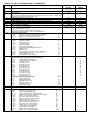
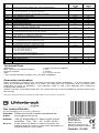
Table of CVs (Configuration Variables)
CV
Description
1
Locomotive address
2
3
Minimum Speed
Acceleration
1 means that every 5 ms the actual speed is increased by 1
If the internal maximum speed is set to 200 (CV5=50 or CV94 = 200), then
acceleration time from 0 to Fmax is 1sec.
Braking inertia (time factor CV3)
Maximum speed (must be greater than CV2)
Middle speed (must be greater than CV2 and less than CV5)
Software version (The processor can be updated)
Manufacturer ID
Long locomotive address
17 = high byte / 18 = low byte
Consist address (double traction)
0 = Consist address inactive
When bit 7=1 the driving direction is reversed
The desired speed CADR + 128 = reverse direction
RailCom Configuration
0*
Bit 0=0
Channel 1 not free for address broadcast
1
Bit 0=1
Channel 1 free for address broadcast
0
Bit 1=0
Channel 2 no data transmission
2
*
Bit 1=1
Channel 2 data transmission allowed
Configuration for DCC
Value
0*
Bit 0=0
Normal direction
1
Bit 0=1
reversed travel
0
Bit 1=0
14 speed steps
2
*
Bit 1=1
28 speed steps
0
Bit 2=0
Only digital operation
4*
Bit 2=1
automatic analog/digital switching
0*
Bit 3=0
RailCom Off
8
Bit 3=1
RailCom On
0*
Bit 4=0
Speed steps using CV 2, CV 5, and CV 6
16
Bit 4=1
Characteristics using CV 67 to CV 94
0*
Bit 5=0
Short address (CV 1)
32
Bit 5=1
Long address (CV 17/18)
Allocation of the function outputs, which are to be activated with
function keys like light and special functions
CV33
Light operation forwards
CV34
Light operation backwards
CV35
Function key f1
CV36
Function key f2
CV37
Function key f3
CV38
Function key f4
CV39
Function key f5
CV40
Function key f6
CV41
Function key f7
CV42
Function key f8
CV43
Function key f9
CV44
Function key f10
CV45
Function key f11
CV46
Function key f12
Assignment of the individual Bits
Value
1
Light output front
Bit 0
2
Bit 1
Light output back
4
Bit 2
Special function A1
8
Special function A2
Bit 3
Shunting mode
16
Bit 4
Start/brake inertia
32
Bit 5
Speed correction forwards
Speed correction reverse
Locomotive decoder configuration
Value
Bit 0=0
Motor load regulation On
0*
Bit 0=1
Motor load regulation Off
1
Bit 1=0
SUSI configured for Sound module
0*
Bit 1=1
SUSI configured for LISSY Mini transmitter
2
Bit 2=0
brakes to 0 in brake section
0*
Bit 2=1
brakes to speed step in CV52
4
Bit 3=0
Data format DCC and Motorola
0*
Bit 3=1
Data format only DCC
8
Bit 4=0
Data format DCC and Motorola
0*
Bit 4=1
Data format only Motorola
16
Bit 5=0
Dimming for A1 and A2 Off
0*
Bit 5=1
Dimming for A1 and A2 On
32
Bit 6=0
Light outputs not swapped
0*
Bit 6=1
Light outputs swapped
64
Bit 7=0
Brake only with brake signal
0*
Bit 7=1
Brake with analog potential
128
4
5
6
7
8
17
18
19
28
29
33-46
47
48
49
Value
range
Default
value
DCC 1-127
Mot 1-80
1-63
1-63
1
2
1-63
1-63
1-63
1-9999
199-231/0-255
1-127
2
48
24
varies
85
2000
199/208
0
3
3
0-255
6
0-63
1
2
4
8
16
32
0
0
0
0
0
0
0
0
0-63
0-63
0-255
32
32
32