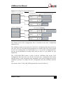
1
xOEMcore IMU navigation sensor fusion module User Manual Confidently. Accurately. Legal Notices Information furnished is believed to be accurate and reliable. However, Oxford Technical Solutions Limited assumes no responsibility for the consequences of use of such information nor for any infringement of patents or other rights of third parties which may result from its use. No license is granted by implication or otherwise under any patent or patent rights of Oxford Technical Solutions Limited. Specifications mentioned in this publication are subject to change without notice and do not represent a commitment on the part of Oxford Technical Solutions Limited. This publication supersedes and replaces all information previously supplied. Oxford Technical Solutions Limited products are not authorised for use as critical components in life support devices or systems without express written approval of Oxford Technical Solutions Limited. All brand names are trademarks of their respective holders. The software is provided by the contributors “as is” and any express or implied warranties, including, but not limited to, the implied warranties of merchantability and fitness for a particular purpose are disclaimed. In no event shall the contributors be liable for any direct, indirect, incidental, special, exemplary, or consequential damages (including, but not limited to, procurement of substitute goods or services; loss of use, data, or profits; or business interruption) however caused and on any theory of liability, whether in contract, strict liability, or tort (including negligence or otherwise) arising in any way out of the use of this software, even if advised of the possibility of such damage. Copyright Notice © Copyright 2015, Oxford Technical Solutions. Revision Document Revision: 150709 (See Revision History for detailed information). Contact Details Oxford Technical Solutions Limited 77 Heyford Park Upper Heyford Oxfordshire OX25 5HD United Kingdom 2 Tel: +44 (0) 1869 238 015 Fax: +44 (0) 1869 238 016 Web: http://www.oxts.com Email: [email protected] Oxford Technical Solutions OEM User Manual Warranty Oxford Technical Solutions Limited warrants OEM products to be free of defects in materials and workmanship, subject to the conditions set forth below, for a period of one year from the Date of Sale. ‘Date of Sale’ shall mean the date of the Oxford Technical Solutions Limited invoice issued on delivery of the product. The responsibility of Oxford Technical Solutions Limited in respect of this warranty is limited solely to product replacement or product repair at an authorised location only. Determination of replacement or repair will be made by Oxford Technical Solutions Limited personnel or by personnel expressly authorised by Oxford Technical Solutions Limited for this purpose. In no event will Oxford Technical Solutions Limited be liable for any indirect, incidental, special or consequential damages whether through tort, contract or otherwise. This warranty is expressly in lieu of all other warranties, expressed or implied, including without limitation the implied warranties of merchantability or fitness for a particular purpose. The foregoing states the entire liability of Oxford Technical Solutions Limited with respect to the products herein. Revision: 150709 3 Table of contents Scope of delivery 6 Introduction 7 External sensor measurements 7 Reference documents 8 Steps to running with an xOEMcore as a navigation system States of an xOEMcore 9 9 XCOM 10 Start-up state NAV configuration files Hardware configuration file Reading the NAV configuration files 12 13 14 15 Initialising state Initialising using GNSS Aiding updates 15 16 17 Locking state 17 Locked state 17 CCOM 18 CCOM checksum calculation 18 CCOM packet types CCOM_TYP_COMMAND CCOM_TYP_CONFIG CCOM_TYP_GPS CCOM_TYP_TACH CCOM_TYP_TRIG 19 20 21 24 26 28 SCOM SCOM packet types SCOM_STATUS_MSG SCOM_TIME_STAMP_MSG SCOM_REQ_CFG_MSG SCOM_GPS1_CMD_MSG, SCOM_GPS2_CMD_MSG RD files XCOM:RD stream 4 30 30 30 31 31 33 34 34 Oxford Technical Solutions xOEMcore User Manual GNSS aiding 36 Primary GNSS measurements 36 Secondary GNSS processing 38 gx/ix™ compatible receivers Settings for u-blox receivers Settings for Topcon B110 receivers Settings for Novatel OEM6 receivers 40 40 45 47 Other receivers Settings for NMEA receivers 48 48 RTCM V3 implementation 50 Revision history 52 Revision: 150709 5 Scope of delivery xOEMcore products are supplied individually in anti-static packaging. No other components or connectors are supplied. The parts are listed in Table 1. Table 1. Summary of xOEMcore delivery Description Qty. xOEMcore 1 The basic xOEMcore is an inertial measurement unit. For additional functionality, it may be delivered with different software options already programmed. The software options available are listed in Table 2. Table 2. Software options Part Description xOEMnav Navigation option added to xOEMcore. xOEMpp Logging and post-processing option added to xOEMcore, requires xOEMnav option. xOEMgxix Differential and gx/ix™ tight-coupling option added to xOEMcore, requires xOEMnav option. xOEMrtk RTK gx/ix™ tight-coupling option added to xOEMcore, requires xOEMnav and xOEMgxix options. Figure 1. xOEMcore delivery 6 Oxford Technical Solutions xOEMcore User Manual Introduction Congratulations on choosing the xOEMcore, a complete inertial measurement unit, inertial navigation system and sensor fusion in one compact package. The inertial measurement unit measures accelerations and rotations; the navigation system integrates these to give position, velocity and orientation; sensor fusion algorithms combine the measurements with other sensors to make all the measurements accurate and avoid errors in the integrated measurements getting larger (drift). Inertial navigation systems are a great way of improving the measurements of other position sensors. The benefits of combining your sensors with an xOEMcore are: High-speed, 100Hz output rate, regardless of the update rate of your sensors. Low-latency, <3 ms output delay, regardless of the latency of your sensors. Continuous position, velocity and orientation, even if your sensors do not output. Smooth position, velocity and orientation, even if your sensors are noisy. Validation of your sensor data, remove erroneous measurements. Fuse multiple sensors in one organised, optimal system. Best of all, you don't need to become a navigation expert to get great results. OxTS has a long history of combining inertial measurements with other sensors and we have put our expertise into the xOEMcore for you to use and benefit from. The xOEMcore is the central navigation component in our own proven products, so you can trust it to deliver great results for you too. External sensor measurements You may be aware that inertial navigation systems give very good short-term results, but drift relatively quickly in the long term. To combat this other sensors (e.g. GNSS) are required to keep the long-term measurements accurate; these are referred to as aiding measurements or aiding updates. The sensor fusion in the xOEMcore uses the aiding measurements to keep all of the inertial measurements as accurate as possible. This distinguishes the xOEMcore from an IMU, where you would have to write the navigation and the sensor fusion algorithms yourself. What is not normally obvious is that the sensor fusion is able to infer indirect corrections from aiding measurements. For example, if you give the xOEMcore position measurements (and nothing else) then it is able to keep roll and pitch accurate; it is able to improve heading when there is horizontal acceleration. Revision: 150709 7 Reference documents This manual describes the operation of the xOEMcore. You will need other OxTS documentation as well in order to use an xOEMcore. The additional documentation is listed in Table 3. Table 3. Other reference documents Ref. Document NDA Description ref. 1 xOEMcore datasheet No The xOEMcore datasheet contains the electrical and mechanical characteristics of the xOEMcore. It should be used when designing hardware that includes the xOEMcore. It also includes all the information needed to use the xOEMcore as an inertial measurement unit (IMU). ref. 2 XCOM description manual No The XCOM description manual describes the XCOM format. XCOM is the container format that is used to create many logical output streams from the single physical serial port on the xOEMcore. ref. 3a NCOM description manual MCOM description manual No The most comprehensive output format from OxTS is NCOM (and MCOM). This is a binary format with all the navigation information in it and most status information. In the xOEMcore you need to separate the logical stream in XCOM that contains NCOM and then decode NCOM to interpret the measurements. ref. 4 NAV configuration manual Yes NAV configuration files and NAV commands are used with all the OxTS products for real-time and post-processing. The xOEMcore needs NAV configuration files at start-up so it knows how to configure itself. The NAV configuration manual describes the NAV configuration files and NAV commands and their contents. It includes the hardware configuration file. ref. 5 Inertial+ integration manuals No The integration manuals are optional, but may give additional information about how to configure the GNSS receiver. They are normally used with the Inertial+ products, where the GNSS receiver is external. Find the integration manuals from the Inertial+ page on the OxTS website. ref. 6 xOEM500 DevKit technical note Yes The description, source code and the schematic diagrams for the xOEM500. ref.3b Where a document is marked “yes” in the NDA column, a non-disclosure agreement is required before OxTS will share the document. 8 Oxford Technical Solutions xOEMcore User Manual Steps to running with an xOEMcore as a navigation system In its basic mode the xOEMcore is an inertial measurement unit (IMU). However, by using the navigation and sensor fusion functions, you get far more benefits. Most of this manual describes how to use the xOEMcore as a navigation system. The xOEMcore datasheet [ref. 1] covers the operation as an IMU. As an overview, the steps to using an xOEMcore as a navigation system are: 1. Turn it on and wait for the configuration request. 2. Send the configuration, followed by the end of configuration command. 3. Start passing the aiding updates (GNSS, wheel speed, other). 4. Send additional information required for initialisation (if needed). That's it, just keep passing aiding updates to improve the outputs. States of an xOEMcore The xOEMcore goes through several states before it is running correctly. These are described in Table 4. Revision: 150709 9 Table 4. xOEMcore states State Description Booting Immediately after power is applied the xOEMcore boots. During this time new firmware can be downloaded (see xOEMcore datasheet [ref. 1] for details). Start-up During start-up the xOEMcore will request and accept NAV configuration files. After the NAV configuration files are acknowledged the xOEMcore will move to the Raw IMU state. Initialising In the initialising state the xOEMcore is waiting for enough information so that it can begin to navigate. To navigate the xOEMcore requires suitable estimates of time, position, velocity and orientation. Using the measurements from the primary GNSS receiver, the xOEMcore can initialise time, position and velocity and it can estimate roll and pitch; the only measurement that cannot be estimated is heading. Heading can be estimated by motion, i.e. be assuming that the vehicle moves in a forward direction. Using dual-GPS the xOEMcore can estimate heading by solving the carrier-phase ambiguities between the two antennas (static initialisation); or heading can be set using a command. While initialising the xOEMcore outputs are delayed by 1 s. Locking When all the conditions for initialisation are available, the xOEMcore starts to navigate. Because the outputs are delayed by 1 s, the xOEMcore needs to “catch up”. This happens over a 10 s period. Locked After the 10 s locking period the xOEMcore runs normally with very low latency. XCOM Before doing anything you are going to have to interpret XCOM, which is the output format of the xOEMcore. XCOM is a container format based on the standard Ogg container format. You can write an XCOM decoder yourself, you can use the standard Ogg libraries, or you can use the libraries in the xOEM500 source code. Refer to the XCOM manual [ref. 2] for detailed information on the XCOM format. Only an overview is presented here. We use a container format to output from the xOEMcore so we can multiplex several data streams on one serial port. The xOEMcore only has one serial port. By using XCOM we can simulate several serial ports, rather than just one. This is shown in Figure 2. 10 Oxford Technical Solutions xOEMcore User Manual Figure 2. XCOM container NCOM SCOM NMEA xOEMcore STX at 1.5 Mbaud NCOM → Ethernet SCOM → Application CPU NMEA → RS232 XCOM RD RD → SD card CAN CAN → CAN bus Logical streams Physical stream Logical streams The role of XCOM is to combine the data streams in the xOEMcore so that they can be transmitted on the xOEMcore's serial port (as a physical stream) and then separated into different logical streams (your data streams) by your application. Once the data streams are separated, you still have to decode them so that they make sense. For example, NMEA can be configured on one of the logical streams. You use XCOM to work out which part of the physical stream is the right NMEA data, then you have to interpret the NMEA to get your latitude, longitude, altitude or any other quantity you want. In Ogg or XCOM terminology, you decode NMEA, NCOM or other message types using a codec. This is shown in Figure 3. Figure 3. XCOM codecs NCOM SCOM NMEA xOEMcore STX at 1.5 Mbaud XCOM NMEA RD Time Latitude Longitude etc. CAN Logical streams Physical stream Logical streams Codec Real meaning In the current implementation of the xOEMcore there are several logical streams and they are intended for specific destinations. Each logical stream has a unique serial ID so your application can route its data to the appropriate codec, or pass it out of the appropriate port (as suggested in Figure 2). The logical streams and serial IDs are listed in Table 5. Revision: 150709 11 Table 5. XCOM serial IDs Serial ID Destination Description 0000 0000h (host) SCOM, which contains LED information, configuration requests, management of raw data files, etc. 0000 0001h SD card RD, raw data. Write this information to a file as it arrives and use it for post-processing. 0000 0010h ser1 The bytes in this data stream are passed straight out of serial port 1. 0000 0050h udp1 The packets in this data stream are broadcast on UPD port 3000 and are normally in NCOM or MCOM formats (depending on the configuration). 0000 0060h udp2 If you want to output XCOM from your application, take the XCOM pages, without decoding them and output them. This is how OxTS outputs XCOM broadcast on UDP 50475 in the xNAV products. Note that this use of serial IDs is different to the Ogg standard; see XCOM manual [ref. 2] for details. The destination listed in Table 5 is not mandatory; this is how we have implemented the xNAV products. The SCOM is normally used by the host microcontroller and deals with configuration and management tasks. The SD card, with RD/raw data in its stream, is intended for a file so that the OxTS post-processing software will work. ser1 is intended for an RS232 or RS422 serial port, but could be used internally by your application, as can udp1 and udp2. To begin using the xOEMcore, start by looking at SCOM and ignore the other logical streams. Start-up state After the firmware in the xOEMcore boots it will configure the serial port at 1.5 Mbaud, 8 data bits, no parity and 1 stop bit. The boot cycle takes about 17 s (TB3 on datasheet). The first output packets are XCOM:SCOM of type SCOM_REQ_CFG_MSG. This is to let you know that the xOEMcore is ready to receive NAV configuration files. NAV configuration files are sent using the CCOM packet CCOM_TYP_CONFIG. See the CCOM_TYP_CONFIG section for information on how to send the NAV configuration files and see the section SCOM_REQ_CFG_MSG for information on how the configuration is requested and acknowledged. The NAV configuration files are not stored in the xOEMcore and must be programmed every time the xOEMcore is turned on. 12 Oxford Technical Solutions xOEMcore User Manual The xOEMcore will leave the start-up state when the NAV configuration files have been received successfully (after you send a CCOM_SUB_END packet). An SCOM_REQ_CFG_MSG packet will be sent with the acknowledgement payload. NAV configuration files The best way to get a set of NAV configuration files is to start with the OxTS PC software called NAVconfig. This generates NAV configuration files for applications using GNSS receivers, but it is still a good starting point for other applications. NAVconfig is shown in Figure 4. Figure 4. NAVconfig product selection page Start with the xNAV family and use the xNAV500 model. Click on the “Save/Finish” link on the left to jump straight to the finish page where the configuration can be saved. The configuration includes several files and should be saved to an empty folder (for clarity). The listing of the folder will be similar to Figure 5. Revision: 150709 13 Figure 5. NAV configuration files The file “mobile.cfg” contains most of the configuration information. The other files contain vectors that describe aspects of the configuration. For example, the “mobile.gap” file contains the lever-arm from the inertial measurement unit to the GNSS antenna; the “mobile.vat” file contains the rotations from the inertial measurement unit axes to the vehicle axes. For the OxTS products the filename is always “mobile” with different file extensions. When sending the configuration to the xOEMcore only the file extension is sent. For example “cfg”, “vat”, etc. The NAV configuration files are described in the NAV configuration manual [ref. 4]. Hardware configuration file There is a special configuration file that is not created by NAVconfig. This is the hardware configuration file. It tells the xOEMcore information about the hardware in your system. Currently this is used to configure the GNSS cards and the serial numbers. OxTS has some reserved fields for use with our own products, for example to record and output what types of PCBs are fitted to our products. Although it does not matter what order the NAV configuration files are sent, we recommend sending the hardware configuration file first. Your hardware configuration file will look similar to Figure 6. 14 Oxford Technical Solutions xOEMcore User Manual Figure 6. Hardware configuration file The serial number can be anything from 0 to 65534. (Do not use “xxxx” as shown in Figure 6). The fields in the hardware configuration file are described in the NAV configuration manual [ref. 4]. This document includes the optional fields. Reading the NAV configuration files Once the xOEMcore leaves its start-up state, the NAV configuration files that have been programmed will be output in the auxiliary headers of the XCOM:RD stream (with some additional framing information). The auxiliary headers can be used to check and verify the configuration that the xOEMcore is using. OxTS has some command line tools that can be used to extract the NAV configuration files from an RD file. Contact OxTS for additional information. Initialising state Once the NAV configuration files have been sent and acknowledged, the xOEMcore enters the initialising state. In this state the xOEMcore is waiting for sufficient information so it can initialise. Table 6 lists the requirements or the xOEMcore to initialise. Table 6. Requirements for initialisation Requirement Description 1PPS A 1PPS pulse is required so that the xOEMcore has an accurate time reference. Time The xOEMcore needs to know the time of the 1PPS pulses. Position The latitude, longitude and altitude of the xOEMcore at a specific time. Velocity The north, east and down velocity of the xOEMcore at a specific time. Orientation The heading, pitch and roll of the xOEMcore at a specific time. Note: the time for the position, velocity and orientation measurements needs to be the same. Revision: 150709 15 While the xOEMcore is in the initialising state, the navigation system buffers up the inertial measurements and runs with a 1 s delay. Transmitting and decoding the position, velocity and orientation is not instant. If the xOEMcore does not buffer and delay the inertial measurements then position, etc. from aiding sensors will be old by the time the xOEMcore has received it and so it cannot be used with the current inertial measurements. By delaying by 1 s, you have about 750 ms to make the measurements and to send them to the xOEMcore. This is shown diagrammatically in Figure 7. Figure 7. Example delay before initialisation to synchronise all measurements Real speed at t = 0 Inertial data buffered for 1s Speed, etc. Time Delayed speed, etc. Measurement e.g. in GPS Serial transmission and decoding Buffered Real speed at t = 0, available in xOEMcore at t = ~0.3 Real speed at t = 0, used to initialise in xOEMcore at t = 1 Initialisation All the outputs from the xOEMcore will be delayed by 1 s during this time. If you move the xOEMcore, it will take 1 s for this movement to be seen in the acceleration and angular rate fields. If time is valid, it will be delayed by 1 s to match the inertial measurements. Initialising using GNSS For systems that use GNSS, the requirements for initialisation are decoded automatically through the normal GNSS processing. You do not need to decode the GNSS information yourself and send the information, just send the GNSS packets and the xOEMcore will initialise itself automatically when it finds the information it needs. The information for initialising using GNSS that the xOEMcore uses is summarised in Table 7. 16 Oxford Technical Solutions xOEMcore User Manual Table 7. Initialisation using GNSS Requirement Description 1PPS The GNSS supplies the 1PPS pulse. Time The xOEMcore decodes the GNSS messages to find the time. It is important that the messages from GNSS are not delayed by too much (e.g. more than 750 ms), or the wrong time will be associated with the 1PPS pulse. Do not buffer any GNSS packets at the start while waiting for the xOEMcore to boot. Position The latitude, longitude and altitude of the primary GNSS antenna are used as an approximate position for the xOEMcore. Velocity The north, east and down velocities of the primary GNSS antenna are used as an approximate position for the xOEMcore. Orientation The pitch and roll are either set to zero (option “vehicle_level”) or are estimated by averaging the Xv and Yx accelerations (option “vehicle_not_level). For most applications setting pitch and roll to zero works very well and the xOEMcore is able to quickly compute better estimates. The heading can either be estimated by forward (or backward) motion, or it can be estimated by a static initialisation (ambiguity search) in a dual-antenna system. Aiding updates During the initialisation state the aiding updates should be sent. For example, wheel speed updates can be sent using CCOM. The xOEMcore cannot normally initialise without some aiding measurements. Locking state When the information to initialise is available, the xOEMcore will start navigating. At this point in time it still has a 1 s delay. During the locking state the xOEMcore will catch up so that it reaches real-time. The xOEMcore always takes 10 s to catch up. Locked state The locked state is the normal operating mode of the xOEMcore. In this mode time is locked and all outputs are available as normal in real time. Aiding updates should continue as normal and can still be delayed by up to about 750 ms. The xOEMcore will continue to navigate until it is reset or the power is turned off. Revision: 150709 17 CCOM CCOM is the format that the xOEMcore uses to receive commands, sensor measurements and other information. It has a variable length and can contain different packet types. It is transmitted as a sequence of 8-bit bytes. A header is used to synchronise and validate the payload data that needs to be sent. The packet structure for CCOM is listed in Table 8. Table 8. CCOM packet format Bytes Format Description 0 uint8 Sync byte, which always has the value 40h. It signals the start of a new CCOM packet and allows resynchronisation of CCOM. Note that 40h can be in other parts of the packet so care has to be taken to correctly identify a sync byte. The CCOM format works best in lossless communication channels where there are rarely any dropped bytes. 1 uint8 Reserved. Should always be 00h in the current implementation. 2 unit8 Header checksum. Checksum of the header (bytes 0 − 7) arranged so that the sum of all the bytes in the header modulo 255 are zero. See checksum calculation code below. 3 uint8 Packet checksum. Checksum of the header bytes 3 − 7 and all the payload data bytes, arranged so that the sum of all the bytes modulo 255 is zero. See checksum calculation code below. 4−5 uint16 Payload data length, transmitted in little endian format. The length includes the 8 bytes of the header, so the payload data can be from 0 to 65527 bytes long. 6, 7 uint8, uint8 Packet sub-type, packet type respectively. (These appear reversed so they can be interpreted as a little-endian uint16). The packet type gives the xOEMcore information on which internal module in the xOEMcore will process the payload data. The packet sub-type tells the module what the payload data contains. For example, all GNSS packets have one packet type; the sub-type can be for the primary GNSS, secondary GNSS, etc. 8− Payload data. The payload data is "payload data length" minus 8 bytes long. CCOM checksum calculation There are two checksums in CCOM and these must be calculated in the correct order. Figure 8 shows example C code for computing the checksum and organising the CCOM packet. 18 Oxford Technical Solutions xOEMcore User Manual Figure 8. CCOM checksum calculation code int WriteCComPkt( unsigned char type, unsigned char subtype, unsigned char* data, unsigned int length ) { unsigned int PktLength = length + 8; unsigned char ccom_header[8] = {CCOM_SYNC, CCOM_RES, 0x0, 0x0, (unsigned char) (PktLength & 0xFF), (unsigned char) ((PktLength & 0xFF00) >> 8), subtype, type}; unsigned char checksum_header = 0; unsigned char checksum_packet = 0; uint16_t i_count = 0; if(PktLength & 0xFFFF0000) { return 0; // 65535 length maxium } // Calculate first part of packet checksum from end of header for(i_count = 4; i_count < 8; i_count++) checksum_packet += ccom_header[i_count]; // Calculate the remaining part of the packet checksum on the data for (i_count = 0; i_count < length; i_count++) checksum_packet += data[i_count]; // Packet checksum so that the total sum is zero ccom_header[3] = (~checksum_packet)+1; // Calculate the header checksum for(i_count = 0; i_count < 8; i_count++) checksum_header += ccom_header[i_count]; // Header checksum so the total sum is zero ccom_header[2] = (~checksum_header)+1; // Write it to the serial port (application specific) WriteToSerialPort(ccom_header, 8); WriteToSerialPort(data, length); return 1; // Success, assuming WriteToSerialPort functions worked. } CCOM packet types The xOEMcore uses different packet types to receive different information and commands. The packet type categorises the information and the packet sub-type defines the specific contents of the payload data. The different packet types are described in Table 9. Revision: 150709 19 Table 9. CCOM packet types Packet type Packet name Description 02h CCOM_TYP_COMMAND Contains a command, see NAV configuration manual [ref. 4]. 05h CCOM_TYP_CONFIG Used to send NAV configuration files. These are used during start-up to configure the xOEMcore. 06h CCOM_TYP_GPS Used to send GNSS measurements. These are sent regularly and are a special set of aiding messages for the sensor fusion algorithms. 07h CCOM_TYP_TACH Used to send wheel speed odometer (tacho) measurements. These are sent regularly and are a special set of aiding messages for the sensor fusion algorithms. 08h CCOM_TYP_TRIG Used to send event trigger information. These can be used to create interpolated measurements that are asynchronous with the normal update epochs. Each of the CCOM packet types in Table 9 are described in the sections below. CCOM_TYP_COMMAND The CCOM_TYPE_COMMAND is used to send commands to the xOEMcore. Commands can be used to initialise the xOEMcore, to change some output formats, etc. Commands make immediate changes to the xOEMcore whereas the configuration is set at start-up. There is only one sub-type in the CCOM_TYP_COMMAND packet type, as listed in Table 10. Table 10. CCOM_TYP_COMMAND packet sub-types Packet sub-type Packet name Description 01h CCOM_SUB_ASCII Used to send ASCII command to the xOEMcore. The commands are described in the NAV configuration manual [ref. 4]. Commands are sent in the payload data portion of the CCOM packet. Commands always start with an exclamation mark, ("!", 21h) and any characters before the exclamation mark are ignored. Commands always end with a carriage return ("\r", 0Dh) or a line feed ("\n", 0Ah). The exclamation mark can be part of the command, so it will not reset the command interpreter. A command does not need to be sent in one packet but can be spread over multiple packets. 20 Oxford Technical Solutions xOEMcore User Manual For example Table 11 shows some sequences of packets and whether they work or not. Table 11. CCOM_TYP_COMMAND packet sub-types Packets (hexadecimal) Payload in ASCII Effect 40 00 18 95 10 00 01 02 0A 21 72 65 73 65 74 0A \n!reset\n Accepted "!reset" 40 00 35 7B 0D 00 01 02 0A 21 72 65 73 40 00 A6 04 13 00 01 02 65 74 0D \n!res et\r None Accepted "!reset" 40 00 AE FC 13 00 01 02 0A 31 32 33 21 72 65 73 65 74 0A \n123!reset\n Accepted "!reset" 40 00 C2 EB 10 00 01 02 0A 21 72 65 40 00 0E 9C 13 00 01 02 21 72 65 73 65 74 0A \n!re !reset\n None Rejected "!re!reset" If NCOM or MCOM is being output then the interpretation of the command messages by the xOEMcore can be seen in the status message fields "command characters received", "command characters skipped", "command packets received" and "command packet errors". CCOM_TYP_CONFIG The CCOM_TYP_CONFIG packet type is used to send and manage the NAV configuration files that configure the xOEMcore. Historically all the OxTS products were configured using a set of files, which were generated by NAVconfig. This scheme has been carried forward to the xOEMcore. Since the xOEMcore does not have a file system, the NAV configuration files must be stored (or created) by the external application and sent to the xOEMcore after it boots. NAV configuration files can only be sent at start-up. Within the CCOM_TYP_CONFIG packet type there are several sub-types, which are listed in Table 12. Table 12. CCOM_TYP_CONFIG packet sub-types Packet sub-type Packet name Description 01h CCOM_SUB_HWCFG Used to send hardware configuration file to the xOEMcore. 02h CCOM_SUB_FILE Used to send normal or "mobile" NAV configuration files to the xOEMcore. FFh CCOM_SUB_END Used to tell the xOEMcore that all the NAV configuration files have been sent. Revision: 150709 21 A new configuration file must start at the beginning of a CCOM packet; several NAV configuration files cannot be sent in the same CCOM packet. Not all the file needs to be transmitted in one packet, but the packets for one file must be sequential. The maximum length for any file is 65535 bytes and files longer than this should not be sent and cannot be used. (Currently a big "cfg" file is about 1 kB so this limitation is not very restrictive.) The format for the payload data is listed in Table 13. Table 13. CCOM_TYP_CONFIG payload data format Bytes Format Description 0 uint8 File counter. Must start at 0 for the first file and must increment whenever a new file starts. 1 uint8 Packet counter. Must start at 0 at the beginning of a file and must increment each time another packet for the same file is sent. 2− File contents. Although CCOM supports packets with data up to 65527, OxTS recommends and tests with packets up to 512 bytes of file data in each CCOM packet. The CCOM_SUB_HWCFG packet is used to send the hardware configuration file. This is a special type of file that tells the xOEMcore about hardware that might be connected to it. This file is essential and the xOEMcore will not run unless it is sent. The format for sending the hardware configuration file is listed in Table 13 and overview is shown in Figure 9. The CCOM_SUB_FILE packet is used for sending the normal NAV configuration files. The first payload packet must contain the file extension as a null-terminated string so that the xOEMcore knows which file is being sent. The format for sending the normal NAV configuration files is listed in Table 13 and is shown in Figure 9. 22 Oxford Technical Solutions xOEMcore User Manual Figure 9. Dividing files into CCOM packets Hardware configuration file CCOM packets Packet sub-type, type 40 00 … 00 00 40 00 … 01 00 40 00 … 02 00 Normal configuration file File extension 40 00 … 00 01 40 00 … 01 01 40 00 … 02 01 cfg\0 The format for the NAV configuration files is described in the NAV configuration manual [ref 4]. The xOEMcore many not run unless all of the NAV configuration files that it needs are sent. The "cfg" file is essential and, depending on its contents, other files will be needed as well. As a starting point, use NAVconfig to save a set of NAV configuration files, then use the documentation to modify these until you arrive at a set suitable for your application. The CCOM_SUB_END packet is used to tell the xOEMcore that all the NAV configuration files have been sent. Do not send any more configuration file packets after this packet is sent. Afterwards only commands can be used to change the way the xOEMcore operates. To change the NAV configuration files the xOEMcore must be reset. The format of the CCOM_SUB_END payload data is listed in Table 14. Revision: 150709 23 Table 14. CCOM_SUB_END payload data format Bytes Format Description 0 uint8 Number of files sent. 1 uint8 Always 00h. 2 uint8 Total number of CCOM_TYP_CONFIG packets sent. CCOM_TYP_GPS The CCOM_TYP_GPS packet type is used for a special form of sensor update, one that comes from GNSS receivers. The xOEMcore contains a vast library of advanced GPS processing, including tight-coupling and differential processing. It is much better to use our GPS processing libraries rather than using generic updates with standard GNSS measurements. Note that this message type may change name to COM_TYP_GNSS in the future but the numeric value may not change. Within the CCOM_TYP_GPS packet type there are different sub-types, which are listed in Table 15. Table 15. CCOM_TYP_GPS packet sub-types Packet sub-type Packet name Description 01h CCOM_SUB_GPS_PRI Pass the data from the primary GNSS receiver in this packet. The format should be configured using the hardware configuration file at start-up. The primary GNSS receiver is used for position and velocity updates. If gx/ix processing is configured then the raw measurements can be combined with the differential corrections in CCOM_SUB_GPS_DIF. 02h CCOM_SUB_GPS_SEC Pass the data from the secondary GNSS receiver in this packet. The format should be configured using the hardware configuration file at start-up. The secondary GNSS receiver is used for heading calculation. Only the raw measurements are used. The primary receiver must also have raw measurements. Ephemeris can come from either receiver. 05h CCOM_SUB_GPS_DIF Pass RTCM V3 differential corrections in this packet. With gx/ix processing the differential corrections will be used to give differential or RTK GPS solutions. The byte data from the GNSS receiver should be sent to the xOEMcore using this packet without modification. It is not necessary for your application to decode the data from the GNSS receiver or RTCM V3 differential reference station. The data in the 24 Oxford Technical Solutions xOEMcore User Manual CCOM packet does not need to contain a full packet from the GNSS receiver or be aligned to the GNSS receiver's packets in any way. The byte data will be interpreted one byte at a time in the xOEMcore without using any packet alignment information from CCOM. Typically your application would send all the new bytes you have received from the GNSS on a regular basis. For example, send all the new bytes received every 50ms. The sensor fusion in the xOEMcore is delayed compared to the real-time processing. The aiding data from GNSS will be accepted up to about 750ms after its measurement time. Timing of the GNSS measurements will come from a timestamp in the GNSS receiver's packet so no additional timestamp is required and the xOEMcore does not use the arrival time to accurately time the GNSS measurements. If NCOM or MCOM is being output by the xOEMcore then there are several fields that can be used to monitor how the xOEMcore is interpreting the GNSS information. These are: Primary GPS characters received Primary GPS characters skipped Primary GPS packets received Primary GPS number of packets too old Secondary GPS characters received Secondary GPS characters skipped Secondary GPS packets received Secondary GPS number of packets too old Differential GPS characters received Differential GPS characters skipped Differential GPS packets received See the NCOM description manual [ref. 3a] or the MCOM description manual [ref. 3b] for additional details. If GNSS is being used to update the xOEMcore then the 1PPS from the GNSS receiver needs to be used as the 1PPS input to the xOEMcore and the xOEMcore time needs to be aligned to GNSS time. It is not possible to have two timing references in the current implementation. Revision: 150709 25 CCOM_TYP_TACH The CCOM_TYP_TACH packet is used to send wheel speed odometer (tachometer) measurements to the xOEMcore. These measurements are included in the sensor fusion algorithms and reduce the drift in position, velocity and attitude. Two Kalman filter updates are used: a body frame velocity update when moving and a zero velocity update when stationary. The lever-arm from IMU measurement point to the centre of the wheel must be specified using the wsp and wsa NAV configuration files. The scaling and accuracy must be configured using the “wheelspeed” and “wspeed_noise” options in the cfg configuration file. An additional configuration option, “fix_position” can be used to freeze the measurement of position that is output when stationary. The CCOM_TYP_TACH packet contains one sub-type, which is listed in Table 16. Table 16. CCOM_TYP_TACH packet sub-types Packet sub-type Packet name Description 02h CCOM_SUB_TACH_PPS Pass wheel speed odometer counts and timing in this packet. The measurements are normally derived from an encoder that is fitted to the wheel of the vehicle. The encoder counts how the wheel is rotating using pulses. As the wheel rotates faster, more pulses can be counted in a fixed period of time. Both single encoders and quadrature encoders (giving direction) can be used. The wheel speed odometer measurements require: the time of the measurement; the period; the number of counts during the period. These are shown in Figure 10. 26 Oxford Technical Solutions xOEMcore User Manual Figure 10. Wheel speed odometer timing 1PPS Time from 1PPS to centre of period Gaps OK Measurement period Count pulses Measurement periods can be consecutive and do not need to have the same duration The time of the measurement period is from the latest 1PPS pulse and a full timestamp, including hours, minutes, seconds, etc. should not be used. The time of the centre of the measurement period should be used. The number of pulses should be counted during the measurement period; for quadrature systems negative numbers should be used when going backwards. There can be gaps between measurement periods or the periods can be consecutive; they should not overlap. Note: in the current implementation of the xOEMcore the quadrature information is not used. However, this is planned in the future. Currently the xOEMcore decides whether it is going forwards or backwards itself and does not use or need direction information. For best results: Timing is very important and should be accurate to 1ms or better. A 10ms timing error can result in the position drift doubling. The wheel speed odometer should be updated every 100ms for best results. Use at least 100 pulses per metre. The format for the CCOM_SUB_TACH_PPS payload data is listed in Table 17. Revision: 150709 27 Table 17. CCOM_SUB_TACH_PPS payload data format Bytes Format Description 0 uint8 Time validity. Bit 0: reserved, set to 0. Bit 1: 0: time is valid; 1: time is invalid and measurement will be ignored. Bits 2 – 7: reserved, set to 0. 1 uint8 Reserved. Set to 00h. 2–9 uint64 Time since last 1PPS pulse given to the xOEMcore of the centre of the wheel speed odometer count period in nanoseconds. 10 – 13 uint32 Time accuracy estimate in nanoseconds. 14 – 17 uint32 Period of wheel speed odometer count measurement. 18 – 21 int32 Number of wheel speed odometer counts in the period. If NCOM or MCOM is being output by the xOEMcore then there are several fields that can be used to monitor how the sensor fusion in the xOEMcore is using the wheel speed odometer information. These are: Innovation wheel speed Wheel speed scale factor Wheel speed scale factor accuracy Wheel speed time of last change Wheel speed duration since last change Wheel speed count See the NCOM description manual [ref. 3a] or the MCOM description manual [ref. 3b] for details. Other quantities are computed by the NCOM decoders. CCOM_TYP_TRIG The CCOM_TYP_TRIG packet is used to send trigger events to the xOEMcore. These events can be used to generate asynchronous measurements, e.g. an NCOM packet or NMEA sentence that is not aligned to the normal inertial measurement sampling. The xOEMcore will use linear interpolation to compute the measurements at the time of the trigger event. The trigger event is also sent out of the XCOM:RD stream so it can be stored in an RD file and used by the post-processing software. The xOEMcore needs the time measurement of the trigger event so it can compute the measurements at this exact time. The CCOM_TYP_TRIG packet must be received by 28 Oxford Technical Solutions xOEMcore User Manual the xOEMcore within 50 ms, otherwise the measurements needed for interpolation may have left the buffers. Both rising edge and falling edge times are supported. There is one CCOM_TYP_TRIG sub-packets, which is listed in Table 18. Table 18. CCOM_TYP_TRIG packet sub-types Packet sub-type Packet name Description 03h CCOM_SUB_TRIG1_PPS Timing for trigger event. The format for the trigger event packets is listed in Table 19. Table 19. CCOM_SUB_TRIG1_PPS payload data format Bytes Format Description 0 uint8 Time validity. Bit 0: reserved, set to 0. Bit 1: 0: time is valid; 1: time is invalid and measurement will be ignored. Bits 2 – 7: reserved, set to 0. 1 uint8 Reserved. Set to 00h. 2–9 uint64 Time since last 1PPS pulse given to the xOEMcore in nanoseconds. 10 – 13 uint32 Time accuracy estimate in nanoseconds. 14 uint8 Trigger type. The trigger type is a number from 0 – 4 that is passed to the NCOM (or MCOM) message. It can be used to identify different trigger events. For example, OxTS uses 0 for Trigger 1 falling; 1 for Trigger 1 rising, etc. 15 – 18 int32 Reserved. Set to -1. Revision: 150709 29 SCOM SCOM is the format that the xOEMcore uses to transmit status and management information. SCOM can only be transmitted in a container format (XCOM) since it relies on the container format to align the packets, for error checking and for the length of the packet. SCOM is transmitted as a sequence of 8-bit bytes. SCOM packet types All SCOM packets are in the format listed in Table 20. Table 20. SCOM packet format Bytes Format Description 0−7 uint64 Reserved. 8−9 uint16 Packet type. 10 − Payload data, dependent on the packet type. Note that the length is known from the XCOM decoder. The different packet types are listed in Table 21. Table 21. SCOM packet types Packet type Packet name Description 0000h SCOM_STATUS_MSG Contains the information for updating the LEDs. 0001h SCOM_TIME_STAMP_MSG Contains a timestamp string, which is used for the name of new RD files. 0606h SCOM_REQ_CFG_MSG Request or acknowledge NAV configuration files. 3147h SCOM_GPS1_CMD_MSG The payload data contains a binary string that should be sent to GNSS1. 3247h SCOM_GPS2_CMD_MSG The payload data contains a binary string that should be sent to GNSS2. Note: the xOEMcore will output other messages, which should be ignored. SCOM_STATUS_MSG The SCOM_STATUS_MSG packet is used by OxTS to configure the colour of the LEDs on the front of the xNAV products. The format for the payload data in the SCOM_STATUS_MSG packet is listed in Table 22. 30 Oxford Technical Solutions xOEMcore User Manual Table 22. SCOM_STATUS_MSG packet format Bytes Format Description 10 uint8 Colour for LED1, labelled SDNav. 11 uint8 Colour for LED2, labelled GNSS. 12 uint8 Reserved for future LEDs. 13 uint8 Reserved for future LEDs. Note that the bytes column gives the offset into the SCOM message; see Table 20 for bytes 0 – 9. The colour for the LEDs is encoded using two unsigned 4-bit nibbles so that the LEDs can be configured to flash. The colour during the two periods of the flash is given in each nibble. Typically the flash period is 1 s, or 500 ms in each state. Normally OxTS uses LED colours listed in Table 23. Table 23. Typical LED colours Value Description 0h Off 1h Red 2h Green 3h Orange (or yellow) Orange is created with the red and green LEDs on. For example, the byte would contain 13h for flashing red (1) – orange (3). SCOM_TIME_STAMP_MSG The SCOM_TIME_STAMP_MSG packet is used by OxTS to create the filename for the RD files. OxTS names RD files in the format yyMMdd_hhmmss.rd, i.e. with the year (yy), month (MM), day (dd), hour (hh), minutes (mm) and seconds (ss). This is the approximate start time, in GPS time, for the RD file. The message may not make sense unless the xOEMcore has GPS time. It is not essential to name RD files in this format. The payload data for the SCOM_TIME_STAMP_MSG packet is always 16 characters starting at byte offset 10. It is in the format yyyyMMdd_hhmmss\0. The terminating null is transmitted. Unlike the OxTS RD filename, the full 4-digit year is transmitted. SCOM_REQ_CFG_MSG The SCOM_REQ_CFG_MSG packet is used by the xOEMcore to request (and acknowledge) the NAV configuration files. It is an essential part of the xOEMcore’s start-up sequence. Revision: 150709 31 After booting, the xOEMcore will output the SCOM_REQ_CFG_MSG packet. This lets the host microcontroller know that the xOEMcore has booted and that the xOEMcore is waiting for the NAV configuration files to be sent (using the CCOM_TYP_CONFIG packet types). The xOEMcore will repeat the SCOM_REG_CFG_MSG packet periodically if nothing is received from the host microcontroller for 5 s. The operation of the SCOM_REQ_CFG_MSG is shown in Figure 11. Figure 11. SCOM_REQ_CFG_MSG operation Time 5s xOEMcore (STX) Host (SRX) Req 5s Req Req Config Ack Config End Config ignored Once the CCOM_SUB_END packet is received the xOEMcore will send an SCOM_REQ_CFG_MSG packet with the payload data indicating an acknowledgement, rather than as a request. The CCOM_SUB_END packet lets the xOEMcore know how many files and packets should have been received. If the correct numbers are not received then the xOEMcore will send an SCOM_REQ_CFG_MSG packet without the acknowledgement set after the CCOM_SUB_END packet is received. If this happens then the configuration needs to be sent again from the start. After the SCOM_REG_CFG_MSG packet is sent with the acknowledgement payload data, no more NAV configuration files will be interpreted; they will be ignored; no more SCOM_REG_CFG_MSG packets will be sent; the xOEMcore will leave its startup state. The different payload data for the SCOM_REG_CFG_MSG is listed in Table 24. 32 Oxford Technical Solutions xOEMcore User Manual Table 24. SCOM_CFG_REQ_MSG payload data Payload data Length Description 00h 1 Request configuration. FFh 00h 2 Acknowledge all NAV configuration files received correctly. FFh 01h 2 Reserved. xOEMcore will not be operating as expected if you receive this. Reset it and check you have configured it as expected. Note that the payload data starts at byte offset 10 in the SCOM_CFG_REQ_MSG. SCOM_GPS1_CMD_MSG, SCOM_GPS2_CMD_MSG The SCOM_GPS1_CMD_MSG packet and the SCOM_GPS2_CMD_MSG packet are used to allow the xOEMcore to send messages to the GNSS receivers. Typically these are used to request ephemeris for the gx/ix processing. The xOEMcore will not pass through options for the GNSS receiver in the cfg file, nor will it pass through the commands that are for the GNSS receiver. These have to be captured by the host microcontroller and sent to the GNSS receiver separately. For example, in the cfg file, the line: ->gps1:hello will not result in an SCOM_GPS1_CMD_MSG being sent out of the xOEMcore. The host microcontroller must ensure that all payload data in these packets are sent straight to the GNSS receivers without modification or re-ordering. The payload data can be ASCII or binary. Revision: 150709 33 RD files To use the advanced post-processing software the RD stream in XCOM has to be captured and written to a file correctly. There are several reasons for including this in your application, including: Reduce drift by processing forwards and backwards in time, then combining the two time-directions. This halves the amount of time that you need to rely on inertial measurements between aiding measurements. For GPS processing with gx/ix™, include RINEX differential correction files, which significantly improves the position accuracy. Recover customer data. In our experience, the main problem with customer data is incorrect configuration. Using post-processing the configuration can be changed and the customer’s data can be fixed. Diagnose customer problems. The RD files have all of the configuration, as well as all the raw measurements, so it is easier to diagnose and fix problems. The xOEMcore writes out the RD file data in a stream in XCOM. The payload data for the stream can be captured and written straight to a file, which will be a valid RD file. The format of the RD file is not disclosed by OxTS and can only be processed using our post-processing software (blended.exe). XCOM:RD stream Like all XCOM or Ogg streams, the XCOM:RD stream will contain: Stream header packet Auxiliary header packets RD payload data Stream footer packet These packets are shown diagrammatically in Figure 12. 34 Oxford Technical Solutions xOEMcore User Manual Figure 12. XCOM:RD packets Do not write to RD file Write all auxiliary headers at the start of an RD file (after removing the pattern <OxTS-RD-Log> from the start) Write all payload data to the RD file RD: Auxiliary header 1 (Other packets) RD: Initial header (Other packets) RD: Footer (Other packets) (Other packets) RD: Payload data (Other packets) (Other packets) RD: Payload data (Other packets) RD: Auxiliary header n (Other packets) RD: Auxiliary header 2 (Other packets) RD: Auxiliary header 1 (Other packets) (Other packets) RD: Initial header XCOM physical stream on STX Do not write to RD file Do not write aux. payload in the middle of an RD file The xOEMcore periodically restarts the XCOM:RD stream (about once every 5 seconds). This allows your application to start a new RD file as required. Note that, for best performance, it is better to have long, continuous RD files rather than lots of smaller files. Each RD file will require initialisation conditions so the xOEMcore can start to navigation and it will have a warm-up period while the sensor fusion tunes the performance. RD files are not robust against dropped characters or incorrect characters since there is only very basic framing information in the file. Do not modify any characters or miss any characters. Occasional missed packets may result in an acceptable RD file but the post-processing software will complain about them. Revision: 150709 35 GNSS aiding GNSS is a very good aiding source for the sensor fusion algorithms and most outdoor applications will benefit from using GNSS. If GNSS is being used in the xOEMcore then it is essential to use GPS Time as the time reference and to use a 1PPS pulse that is aligned to GPS as the master clock reference. It is not currently possible to have a fixed or variable time offset between the xOEMcore time and GPS Time. Primary GNSS measurements There are two ways to use GNSS in the xOEMcore. These are: Feed the position and velocity measurements from the GNSS to the xOEMcore. This is often referred to as loose coupling. Feed the raw satellite pseudo-range and carrier phase measurements from the GPS to the xOEMcore. This is often referred to as tight coupling and our implementation is called gx/ix™ processing. In the current implementation of gx/ix™ processing only raw GPS measurements, and no other satellite systems, are used. However, it is still often better to use gx/ix processing, with fewer satellites, than to use GPS and GLONASS processed by the receiver. GLONASS processing is in development at the moment and will be available soon. In open sky environments there is little difference between loose coupling and tight coupling. The advantages of tight coupling are: Better satellite rejection. The xOEMcore is able to use its prior knowledge of the antenna’s position to reject satellite measurements that are inaccurate. By contrast, the GNSS receiver has to decide which satellites are good or poor only using satellite measurements; in poor GNSS conditions the receiver often rejects the wrong satellites or has to use satellites with poor measurements anyway. Sensor fusion using less than 4 satellites. The xOEMcore is able to update the navigation solution even if there are less than 4 satellites in view. Although this may not be a full 3D update, it does constrain the navigation system in some directions and reduces drift rate. Using the tight coupling algorithms the xOEMcore is able to estimate the velocity more accurately than GNSS receivers. Many receivers use velocity filters, or noisy Doppler estimates, or have poor timing for velocity measurements. Using the raw measurements the xOEMcore is able to mitigate these problems and has much better control of velocity. This control is important: if you have a velocity error of 36 Oxford Technical Solutions xOEMcore User Manual 3 cm/s then, without GNSS, you will drift by at least 3 cm in 1 second, or 30 cm in 10 seconds. With a 1 cm/s velocity error the drift is 3 times lower. Velocity has a big influence on drift rate and its measurement, calculation and timing are very important. Using the raw data from GPS and the OxTS gx/ix™ processing, you can have differential and inertially-aided RTK, which give significantly better positioning than the normal standard positioning service (SPS) of GNSS. We call our tight coupling algorithms the gx/ix™ processing and the differential processing is included in these algorithms. Where possible, OxTS recommends using raw data from GPS and using the gx/ix™ processing. The gx/ix™ processing can only be enabled if the correct feature codes have been programmed into the xOEMcore. The processing method selected for GPS measurements is configured using the options starting “rcvgps” and “rawgps” in the “cfg” configuration file. See the NAV configuration manual [ref. 4] for a description of the options. Although it is possible to enable both the GPS receiver’s measurements and the gx/ix™ measurements, this is not recommended and it will make the sensor fusion over confident in its position and velocity measurements. There are several other configuration options that can be used to configure how the GNSS measurements are used. These include: high_accuracy, low_accuracy and poor_accuracy low_vibration, high_vibration and very_high_vibration gpsposrej_lim, gpsvelrej_lim The lever-arm from the inertial measurement unit to the phase-centre of the primary GNSS antenna is configured using the “gap” configuration file and the accuracy of this measurement is configured using the “gaa” configuration file. See the NAV configuration manual [ref. 4] for a description of these files. The sensor fusion algorithms will try to improve the lever-arm measurement. The sensor fusion algorithms work much better with RTK quality position measurements than with differential or standard positioning service quality measurements. The actual lever-arm being used by the sensor fusion algorithms can be monitored using the following NCOM outputs: GPS antenna lever-arm Xi GPS antenna lever-arm Yi GPS antenna lever-arm Zi Revision: 150709 37 GPS antenna lever-arm accuracy Xi GPS antenna lever-arm accuracy Yi GPS antenna lever-arm accuracy Zi Note that these are in the inertial measurement unit’s co-ordinate frame and not the vehicle’s co-ordinate frame. Before turning off the xOEMcore, it is possible to check that these improvements are reasonable and to update the “gap” and “gaa” files using these improved measurements so that the xOEMcore starts with better measurements next time it is turned on. Secondary GNSS processing The xOEMcore is able to use the measurements from two GNSS antennas to compute a heading measurement. Normally two separate GNSS receivers are used, one for each antenna. This functionality only works if: Both antennas and GNSS receivers are the same type. Raw GPS measurements are output by both receivers for the same time epoch. The raw data from the receivers is supported by OxTS (i.e. the receiver can be used for gx/ix™ processing). Typically the antennas should be within 5 m of each other. The accuracy of the heading measurement improves as the antennas are further apart and is typically 0.2° per metre of horizontal separation. The xOEMcore measures the relative position of the secondary antenna compared to the primary antenna using RTK ambiguity resolution and carrier phase measurements. The xOEMcore can resolve the RTK ambiguities using both single frequency (L1) and dual-frequency (L1/L2) measurements, giving a measurement that is sub-centimetre accurate. The secondary receiver can be a single frequency receiver, which is generally much less expensive than a dual-frequency receiver. Since the receivers should be the same type, this is normally achieved by only purchasing a single frequency software license on a dual-frequency capable receiver. In normal operation the heading ambiguities are resolved using the inertial measurements; an ambiguity search is not required and the L2 signal has no benefit. The benefits of using an L2 signal are: 1. When you first start the xOEMcore and heading is not known. The xOEMcore can use “static initialisation”, which is an RTK ambiguity search, to measure heading. This is much quicker and more reliable with L1/L2 receivers, especially with larger antenna separations. 38 Oxford Technical Solutions xOEMcore User Manual 2. When you first start, the xOEMcore does not normally know the heading angle of the GNSS antennas compared to the heading angle of the inertial measurement unit. Even if the xOEMcore knows the heading of the inertial measurement unit, it cannot compute an accurate angle for the GNSS antennas. This prevents the xOEMcore from using inertial heading to resolve the RTK ambiguities and a normal ambiguity search is required (where L2 is much quicker). Once the inertial heading and the GPS-heading is known then the offset angle can be found and, in the future, the RTK ambiguities can be resolved using the inertial measurements; L2 has no significant benefit. The sensor fusion algorithms in the xOEMcore are very good at measuring this offset angle. On a system where the antennas cannot change angle compared to the inertial measurement unit, the offset angle measured by the sensor fusion algorithms can be programmed into the NAV configuration files so that it does not need to be found next time and item (2) does not occur. The options that configure the dual-antenna system are: blength heading_never, heading_postinit, heading_nosearch, heading_always gps_pitch See the NAV configuration manual [ref 4.] for a description of the options. By default, the xOEMcore needs to know the separation between the antennas more accurately than 5 cm. The offset angles of the GNSS antennas compared to the inertial measurement unit are configured using the “att” file and the accuracy of this measurement is configured using the “ata” configuration file. Typically OxTS uses an accuracy of 5°, which works well with separations up to 2 m; above 2 m it is sometimes necessary to measure more accurately in order to avoid item (2) above. The sensor fusion algorithms will try to improve the offset angles. Since this angle is virtually impossible to measure, it is much better to let the sensor fusion algorithms estimate the angles rather than try to measure it accurately. Typically the sensor fusion can measure the offset angles with an accuracy of 0.02° or better. The actual offset angles being used by the sensor fusion algorithms can be monitored using the following NCOM outputs: Dual antenna heading offset Dual antenna pitch offset Dual antenna heading offset accuracy Revision: 150709 39 Dual antenna pitch offset accuracy Dual antenna baseline length Dual antenna baseline length accuracy Note that in the current implementation the baseline length (separation) is estimated internally but the output is the configured value, not the value computed internally. The accuracy is the configured accuracy. The offset angles are configured and output as the rotation from the inertial measurement unit to the GNSS antenna angles; this can include a singularity when the pitch angle is ±90°. The algorithms in the xOEMcore are robust to this but it can cause problems for customers and the accuracy is hard to define or interpret. gx/ix™ compatible receivers For a receiver to be compatible with the gx/ix™ processing algorithms OxTS must have interpreted its raw data and must have built a suitable sensor fusion model. The receivers that can be used with the gx/ix™ processing algorithms are listed in Table 25. Table 25. gx/ix™ compatible receivers Manufacturer Model Description u-blox LEA6T Low-cost, very capable L1-only receiver. Achieves 50 cm CEP position accuracy using differential corrections. Topcon B110 Small L1/L2 receiver. Achieves 2 cm CEP position accuracy using differential corrections. Requires careful configuration as raw measurements can be filtered, causing problems. Novatel OEM6 Various form-factors. Achieves 1 cm CEP position accuracy using differential corrections. OxTS has tested other receivers, particularly some from Trimble and NavCom, with our other products. If there is a receiver that you particularly want to use then please contact OxTS. We may be able to support it relatively easily. Settings for u-blox receivers To configure the xOEMcore to expect u-blox receivers set the fields in the hardware configuration file as shown in Table 26. 40 Oxford Technical Solutions xOEMcore User Manual Table 26. u-blox LEA6 hardware configuration file settings Setting Description gps1=LEA6 Configure the primary GNSS as a u-blox LEA6 receiver. gps2=LEA6 Configure the secondary GNSS as a u-blox LEA6 receiver. If no secondary GNSS is fitted then use “gps2=None”. Gps1PosRate=4Hz Set the expected update rate for position measurements to 4Hz. Other rates are supported but this is the recommended update rate. This setting will only be used if the receiver’s position is being used. It is not used with the gx/ix™ processing. Gps1VelRate=4Hz Set the expected update rate for velocity measurements to 4Hz. Other rates are supported but this is the recommended update rate. This setting will only be used if the receiver’s velocity is being used. It is not used with the gx/ix™ processing. Gps1RawRate=4Hz Set the expected update rate for raw measurements to 4Hz. Other rates are supported but this is the recommended update rate. This setting affects the gx/ix™ processing and the heading processing, but not the processing of the receiver’s calculations. Gps2RawRate=4Hz Set the expected update rate for raw measurements of the secondary receiver to 4Hz. Other rates are supported by this is the recommended update rate. This setting affects the gx/ix™ processing and the heading processing, but not the processing of the receiver’s calculations. The u-blox LEA6 working as the primary GNSS should be configured from its default settings using the following commands. MON-VER - 0A 04 46 00 37 2E 30 33 20 28 34 35 39 37 30 29 00 00 00 00 00 00 00 00 00 00 00 00 00 00 00 00 00 00 30 30 30 34 30 30 30 37 00 00 37 2E 30 33 20 28 34 35 39 36 39 29 00 00 00 00 00 00 00 00 00 00 00 00 00 00 00 00 00 00 CFG-ANT - 06 13 04 00 1F 00 2D A2 CFG-DAT - 06 06 2C 00 00 00 00 40 A6 54 58 41 88 6D 74 96 1D A4 72 40 00 00 00 00 00 00 00 00 00 00 00 00 00 00 00 00 00 00 00 00 00 00 00 00 00 00 00 00 CFG-FXN - 06 0E 24 00 1C 00 00 00 C0 D4 01 00 C0 D4 01 00 C0 27 09 00 C0 27 09 00 A0 8C 00 00 40 77 1B 00 00 00 00 00 00 84 0C 24 CFG-INF - 06 02 0A 00 00 00 00 00 00 00 87 00 00 00 CFG-INF - 06 02 0A 00 01 00 00 00 00 87 00 87 87 87 CFG-INF - 06 02 0A 00 03 00 00 00 00 00 00 00 00 00 CFG-ITFM - 06 39 08 00 F3 AC 62 2D 1E 03 00 00 CFG-MSG - 06 01 08 00 01 01 00 00 00 00 00 00 CFG-MSG - 06 01 08 00 01 02 00 01 00 00 00 00 CFG-MSG - 06 01 08 00 01 03 00 01 00 00 00 00 CFG-MSG - 06 01 08 00 01 04 00 01 00 00 00 00 CFG-MSG - 06 01 08 00 01 06 00 01 00 00 00 00 CFG-MSG - 06 01 08 00 01 11 00 00 00 00 00 00 CFG-MSG - 06 01 08 00 01 12 00 01 00 00 00 00 CFG-MSG - 06 01 08 00 01 20 00 01 00 00 00 00 CFG-MSG - 06 01 08 00 01 21 00 00 00 00 00 00 CFG-MSG - 06 01 08 00 01 22 00 00 00 00 00 00 CFG-MSG - 06 01 08 00 01 30 00 01 00 00 00 00 CFG-MSG - 06 01 08 00 01 31 00 00 00 00 00 00 CFG-MSG - 06 01 08 00 01 32 00 00 00 00 00 00 CFG-MSG - 06 01 08 00 02 10 00 01 00 00 00 00 CFG-MSG - 06 01 08 00 02 11 00 00 00 00 00 00 CFG-MSG - 06 01 08 00 02 20 00 00 00 00 00 00 CFG-MSG - 06 01 08 00 02 23 00 00 00 00 00 00 Revision: 150709 41 CFG-MSG - 06 01 08 00 02 30 00 00 00 00 00 00 CFG-MSG - 06 01 08 00 02 31 00 01 00 00 00 00 CFG-MSG - 06 01 08 00 0A 02 00 00 01 00 00 00 CFG-MSG - 06 01 08 00 0A 05 00 00 01 00 00 00 CFG-MSG - 06 01 08 00 0A 06 00 00 00 00 00 00 CFG-MSG - 06 01 08 00 0A 07 00 00 00 00 00 00 CFG-MSG - 06 01 08 00 0A 08 00 00 01 00 00 00 CFG-MSG - 06 01 08 00 0A 09 00 01 00 00 00 00 CFG-MSG - 06 01 08 00 0A 0A 00 00 00 00 00 00 CFG-MSG - 06 01 08 00 0A 20 00 00 00 00 00 00 CFG-MSG - 06 01 08 00 0A 21 00 00 00 00 00 00 CFG-MSG - 06 01 08 00 0B 00 00 00 00 00 00 00 CFG-MSG - 06 01 08 00 0B 05 00 00 00 00 00 00 CFG-MSG - 06 01 08 00 0B 30 00 00 00 00 00 00 CFG-MSG - 06 01 08 00 0B 31 00 00 00 00 00 00 CFG-MSG - 06 01 08 00 0B 32 00 00 00 00 00 00 CFG-MSG - 06 01 08 00 0B 33 00 00 00 00 00 00 CFG-MSG - 06 01 08 00 0D 01 00 00 00 00 00 00 CFG-MSG - 06 01 08 00 0D 03 00 01 00 00 00 00 CFG-MSG - 06 01 08 00 0D 06 00 00 00 00 00 00 CFG-MSG - 06 01 08 00 0D 04 00 00 00 00 00 00 CFG-MSG - 06 01 08 00 F0 00 00 00 00 01 01 01 CFG-MSG - 06 01 08 00 F0 01 00 00 00 01 01 01 CFG-MSG - 06 01 08 00 F0 02 00 00 00 01 01 01 CFG-MSG - 06 01 08 00 F0 03 00 00 00 01 01 01 CFG-MSG - 06 01 08 00 F0 04 00 00 00 01 01 01 CFG-MSG - 06 01 08 00 F0 05 00 00 00 01 01 01 CFG-MSG - 06 01 08 00 F0 06 00 00 00 00 00 00 CFG-MSG - 06 01 08 00 F0 07 00 00 00 00 00 00 CFG-MSG - 06 01 08 00 F0 08 00 00 00 01 01 01 CFG-MSG - 06 01 08 00 F0 09 00 00 00 00 00 00 CFG-MSG - 06 01 08 00 F0 0A 00 00 00 00 00 00 CFG-MSG - 06 01 08 00 F1 00 00 00 00 00 00 00 CFG-MSG - 06 01 08 00 F1 03 00 00 00 00 00 00 CFG-MSG - 06 01 08 00 F1 04 00 00 00 00 00 00 CFG-NAV5 - 06 24 24 00 FF FF 08 02 00 00 00 00 10 27 00 00 05 00 FA 00 FA 00 64 00 2C 01 00 00 00 00 00 00 00 00 00 00 00 00 00 00 CFG-NAVX5 - 06 23 28 00 00 00 FF FF 03 00 00 00 03 02 04 10 0A 00 01 01 00 00 F8 05 00 00 00 00 01 01 00 00 00 64 78 00 00 00 00 00 00 00 00 00 CFG-NMEA - 06 17 04 00 00 23 00 02 CFG-PM - 06 32 18 00 00 06 00 00 04 81 00 00 E0 03 1C 00 80 FC 0A 00 80 3A 09 00 24 00 78 00 CFG-PM2 - 06 3B 2C 00 01 06 00 00 00 81 00 00 E0 03 1C 00 80 FC 0A 00 80 3A 09 00 24 00 78 00 2C 01 00 00 4F C1 03 00 86 02 00 00 FE 00 00 00 64 40 01 00 CFG-PRT - 06 00 14 00 00 00 42 00 84 00 00 00 00 00 00 00 00 00 00 00 00 00 00 00 CFG-PRT - 06 00 14 00 01 00 00 00 C0 08 00 00 00 C2 01 00 01 00 01 00 00 00 00 00 CFG-PRT - 06 00 14 00 02 00 42 00 C0 08 00 00 80 25 00 00 00 00 00 00 00 00 00 00 CFG-PRT - 06 00 14 00 03 00 42 00 00 00 00 00 00 00 00 00 03 00 03 00 00 00 00 00 CFG-PRT - 06 00 14 00 04 00 00 00 00 32 00 00 00 00 00 00 07 00 07 00 00 00 00 00 CFG-RATE - 06 08 06 00 FA 00 01 00 01 00 CFG-RINV - 06 34 18 00 00 4E 6F 74 69 63 65 3A 20 6E 6F 20 64 61 74 61 20 73 61 76 65 64 21 00 CFG-RXM - 06 11 02 00 08 00 CFG-SBAS - 06 16 08 00 00 00 00 00 00 00 00 00 CFG-TMODE - 06 1D 1C 00 00 00 00 00 00 00 00 00 00 00 00 00 00 00 00 00 00 00 00 00 00 00 00 00 00 00 00 00 42 Oxford Technical Solutions xOEMcore User Manual CFG-TMODE2 - 06 3D 1C 00 00 00 00 00 00 00 00 00 00 00 00 00 00 00 00 00 00 00 00 00 00 00 00 00 00 00 00 00 CFG-TP - 06 07 14 00 40 42 0F 00 E8 03 00 00 FF 01 00 00 32 00 00 00 00 00 00 00 CFG-TP5 - 06 31 20 00 00 29 03 00 32 00 00 00 40 42 0F 00 40 42 0F 00 00 00 00 00 E8 03 00 00 00 00 00 00 B7 00 00 00 CFG-TP5 - 06 31 20 00 01 29 03 00 32 00 00 00 0A 00 00 00 05 00 00 00 01 00 00 00 20 08 40 00 F7 05 21 00 10 00 00 00 CFG-USB - 06 1B 6C 00 46 15 A4 01 00 00 00 00 64 00 02 00 75 2D 62 6C 6F 78 20 41 47 00 00 00 00 00 00 00 00 00 00 00 00 00 00 00 00 00 00 00 00 00 00 00 41 4E 54 41 52 49 53 28 72 29 20 34 20 20 2D 20 20 47 50 53 20 52 65 63 65 69 76 65 72 00 00 00 00 00 00 00 00 00 00 00 00 00 00 00 00 00 00 00 00 00 00 00 00 00 00 00 00 00 00 00 00 00 00 00 The u-blox LEA6 working as the secondary GNSS should be configured from its default settings using the following commands. MON-VER - 0A 04 46 00 37 2E 30 33 20 28 34 35 39 37 30 29 00 00 00 00 00 00 00 00 00 00 00 00 00 00 00 00 00 00 30 30 30 34 30 30 30 37 00 00 37 2E 30 33 20 28 34 35 39 36 39 29 00 00 00 00 00 00 00 00 00 00 00 00 00 00 00 00 00 00 CFG-ANT - 06 13 04 00 1F 00 2D A2 CFG-DAT - 06 06 2C 00 00 00 00 40 A6 54 58 41 88 6D 74 96 1D A4 72 40 00 00 00 00 00 00 00 00 00 00 00 00 00 00 00 00 00 00 00 00 00 00 00 00 00 00 00 00 CFG-FXN - 06 0E 24 00 1C 00 00 00 C0 D4 01 00 C0 D4 01 00 C0 27 09 00 C0 27 09 00 A0 8C 00 00 40 77 1B 00 00 00 00 00 00 84 0C 24 CFG-INF - 06 02 0A 00 00 00 00 00 00 00 87 00 00 00 CFG-INF - 06 02 0A 00 01 00 00 00 00 87 00 87 87 87 CFG-INF - 06 02 0A 00 03 00 00 00 00 00 00 00 00 00 CFG-ITFM - 06 39 08 00 F3 AC 62 2D 1E 03 00 00 CFG-MSG - 06 01 08 00 01 01 00 00 00 00 00 00 CFG-MSG - 06 01 08 00 01 02 00 01 00 00 00 00 CFG-MSG - 06 01 08 00 01 03 00 01 00 00 00 00 CFG-MSG - 06 01 08 00 01 04 00 01 00 00 00 00 CFG-MSG - 06 01 08 00 01 06 00 01 00 00 00 00 CFG-MSG - 06 01 08 00 01 11 00 00 00 00 00 00 CFG-MSG - 06 01 08 00 01 12 00 01 00 00 00 00 CFG-MSG - 06 01 08 00 01 20 00 01 00 00 00 00 CFG-MSG - 06 01 08 00 01 21 00 00 00 00 00 00 CFG-MSG - 06 01 08 00 01 22 00 00 00 00 00 00 CFG-MSG - 06 01 08 00 01 30 00 01 00 00 00 00 CFG-MSG - 06 01 08 00 01 31 00 00 00 00 00 00 CFG-MSG - 06 01 08 00 01 32 00 00 00 00 00 00 CFG-MSG - 06 01 08 00 02 10 00 01 00 00 00 00 CFG-MSG - 06 01 08 00 02 11 00 00 00 00 00 00 CFG-MSG - 06 01 08 00 02 20 00 00 00 00 00 00 CFG-MSG - 06 01 08 00 02 23 00 00 00 00 00 00 CFG-MSG - 06 01 08 00 02 30 00 00 00 00 00 00 CFG-MSG - 06 01 08 00 02 31 00 01 00 00 00 00 CFG-MSG - 06 01 08 00 0A 02 00 00 01 00 00 00 CFG-MSG - 06 01 08 00 0A 05 00 00 01 00 00 00 CFG-MSG - 06 01 08 00 0A 06 00 00 00 00 00 00 CFG-MSG - 06 01 08 00 0A 07 00 00 00 00 00 00 CFG-MSG - 06 01 08 00 0A 08 00 00 01 00 00 00 CFG-MSG - 06 01 08 00 0A 09 00 01 00 00 00 00 CFG-MSG - 06 01 08 00 0A 0A 00 00 00 00 00 00 CFG-MSG - 06 01 08 00 0A 20 00 00 00 00 00 00 CFG-MSG - 06 01 08 00 0A 21 00 00 00 00 00 00 CFG-MSG - 06 01 08 00 0B 00 00 00 00 00 00 00 CFG-MSG - 06 01 08 00 0B 05 00 00 00 00 00 00 CFG-MSG - 06 01 08 00 0B 30 00 00 00 00 00 00 CFG-MSG - 06 01 08 00 0B 31 00 00 00 00 00 00 Revision: 150709 43 CFG-MSG - 06 01 08 00 0B 32 00 00 00 00 00 00 CFG-MSG - 06 01 08 00 0B 33 00 00 00 00 00 00 CFG-MSG - 06 01 08 00 0D 01 00 00 00 00 00 00 CFG-MSG - 06 01 08 00 0D 03 00 01 00 00 00 00 CFG-MSG - 06 01 08 00 0D 06 00 00 00 00 00 00 CFG-MSG - 06 01 08 00 0D 04 00 00 00 00 00 00 CFG-MSG - 06 01 08 00 F0 00 00 00 00 01 01 01 CFG-MSG - 06 01 08 00 F0 01 00 00 00 01 01 01 CFG-MSG - 06 01 08 00 F0 02 00 00 00 01 01 01 CFG-MSG - 06 01 08 00 F0 03 00 00 00 01 01 01 CFG-MSG - 06 01 08 00 F0 04 00 00 00 01 01 01 CFG-MSG - 06 01 08 00 F0 05 00 00 00 01 01 01 CFG-MSG - 06 01 08 00 F0 06 00 00 00 00 00 00 CFG-MSG - 06 01 08 00 F0 07 00 00 00 00 00 00 CFG-MSG - 06 01 08 00 F0 08 00 00 00 01 01 01 CFG-MSG - 06 01 08 00 F0 09 00 00 00 00 00 00 CFG-MSG - 06 01 08 00 F0 0A 00 00 00 00 00 00 CFG-MSG - 06 01 08 00 F1 00 00 00 00 00 00 00 CFG-MSG - 06 01 08 00 F1 03 00 00 00 00 00 00 CFG-MSG - 06 01 08 00 F1 04 00 00 00 00 00 00 CFG-NAV5 - 06 24 24 00 FF FF 08 02 00 00 00 00 10 27 00 00 05 00 FA 00 FA 00 64 00 2C 01 00 00 00 00 00 00 00 00 00 00 00 00 00 00 CFG-NAVX5 - 06 23 28 00 00 00 FF FF 03 00 00 00 03 02 04 10 0A 00 01 01 00 00 F8 05 00 00 00 00 01 01 00 00 00 64 78 00 00 00 00 00 00 00 00 00 CFG-NMEA - 06 17 04 00 00 23 00 02 CFG-PM - 06 32 18 00 00 06 00 00 04 81 00 00 E0 03 1C 00 80 FC 0A 00 80 3A 09 00 24 00 78 00 CFG-PM2 - 06 3B 2C 00 01 06 00 00 00 81 00 00 E0 03 1C 00 80 FC 0A 00 80 3A 09 00 24 00 78 00 2C 01 00 00 4F C1 03 00 86 02 00 00 FE 00 00 00 64 40 01 00 CFG-PRT - 06 00 14 00 00 00 42 00 84 00 00 00 00 00 00 00 00 00 00 00 00 00 00 00 CFG-PRT - 06 00 14 00 01 00 00 00 C0 08 00 00 00 C2 01 00 01 00 01 00 00 00 00 00 CFG-PRT - 06 00 14 00 02 00 42 00 C0 08 00 00 80 25 00 00 00 00 00 00 00 00 00 00 CFG-PRT - 06 00 14 00 03 00 42 00 00 00 00 00 00 00 00 00 03 00 03 00 00 00 00 00 CFG-PRT - 06 00 14 00 04 00 00 00 00 32 00 00 00 00 00 00 07 00 07 00 00 00 00 00 CFG-RATE - 06 08 06 00 FA 00 01 00 01 00 CFG-RINV - 06 34 18 00 00 4E 6F 74 69 63 65 3A 20 6E 6F 20 64 61 74 61 20 73 61 76 65 64 21 00 CFG-RXM - 06 11 02 00 08 00 CFG-SBAS - 06 16 08 00 00 00 00 00 00 00 00 00 CFG-TMODE - 06 1D 1C 00 00 00 00 00 00 00 00 00 00 00 00 00 00 00 00 00 00 00 00 00 00 00 00 00 00 00 00 00 CFG-TMODE2 - 06 3D 1C 00 00 00 00 00 00 00 00 00 00 00 00 00 00 00 00 00 00 00 00 00 00 00 00 00 00 00 00 00 CFG-TP - 06 07 14 00 40 42 0F 00 E8 03 00 00 FF 01 00 00 32 00 00 00 00 00 00 00 CFG-TP5 - 06 31 20 00 00 29 03 00 32 00 00 00 40 42 0F 00 40 42 0F 00 00 00 00 00 E8 03 00 00 00 00 00 00 B7 00 00 00 CFG-TP5 - 06 31 20 00 01 29 03 00 32 00 00 00 0A 00 00 00 05 00 00 00 01 00 00 00 20 08 40 00 F7 05 21 00 10 00 00 00 CFG-USB - 06 1B 6C 00 46 15 A4 01 00 00 00 00 64 00 02 00 75 2D 62 6C 6F 78 20 41 47 00 00 00 00 00 00 00 00 00 00 00 00 00 00 00 00 00 00 00 00 00 00 00 41 4E 54 41 52 49 53 28 72 29 20 34 20 20 2D 20 20 47 50 53 20 52 65 63 65 69 76 65 72 00 00 00 00 00 00 00 00 00 00 00 00 00 00 00 00 00 00 00 00 00 00 00 00 00 00 00 00 00 00 00 00 00 00 00 44 Oxford Technical Solutions xOEMcore User Manual Although the LEA6 may be able to operate at 10Hz, there is no benefit to the xOEMcore with running at this rate. Its outputs will not be more accurate. The xOEMcore can only accept u-blox binary packets; do not add any NMEA or other non-ublox packet formats. All binary packets will be output in the XCOM:RD stream so that they can be stored in an RD file. Settings for Topcon B110 receivers To configure the xOEMcore to expect Topcon B110 receivers set the fields in the hardware configuration file as shown in Table 27. Table 27. Topcon B110 hardware configuration file settings Setting Description gps1=B110 Configure the primary GNSS as a Topcon B110 receiver. gps2=B110 Configure the secondary GNSS as a Topcon B110 receiver. If no secondary GNSS is fitted then use “gps2=None”. Gps1PosRate=5Hz Set the expected update rate for position measurements to 5Hz. Other rates are supported but this is the recommended update rate. This setting will only be used if the receiver’s position is being used. It is not used with the gx/ix™ processing. Gps1VelRate=5Hz Set the expected update rate for velocity measurements to 5Hz. Other rates are supported but this is the recommended update rate. This setting will only be used if the receiver’s velocity is being used. It is not used with the gx/ix™ processing. Gps1RawRate=5Hz Set the expected update rate for raw measurements to 5Hz. Other rates are supported but this is the recommended update rate. This setting affects the gx/ix™ processing and the heading processing, but not the processing of the receiver’s calculations. Gps2RawRate=5Hz Set the expected update rate for raw measurements of the secondary receiver to 5Hz. Other rates are supported by this is the recommended update rate. This setting affects the gx/ix™ processing and the heading processing, but not the processing of the receiver’s calculations. The Topcon B110 working as the primary GNSS should be configured from its default settings using the following commands. These commands assume that serial port “c” is used to send packets to the xOEMcore and serial port “d” is used for differential corrections. Other serial port combinations may be used. set,/par/ant/rcv/inp,ext set,/par/dev/pps/a/edge,fall set,/par/dev/pps/a/time,gps set,/par/raw/pll/band,30 set,/par/raw/pll/order,3 set,/par/raw/dopp/band,7 set,/par/raw/msint,100 set,/par/pos/msint,100 dm,/dev/ser/d set,/par/dev/ser/d/rate,115200 Revision: 150709 45 set,/par/dev/ser/d/imode,rtcm3 set,/par/lock/waas/sat,off set,/par/pos/cd/src/sbas,off set,pos/mode/cd,y set,pos/mode/cur,cd set,pos/pd/mode,extrap set,/par/pos/rtk/dynamic,kinematic set,/par/pos/pd/dyn,1 set,pos/mode/cur,pd em,/dev/ser/c,jps/RT:0.2 em,/dev/ser/c,jps/RD:0.2 em,/dev/ser/c,jps/TO:0.2 em,/dev/ser/c,jps/BP:0.2 em,/dev/ser/c,jps/ST:0.2 em,/dev/ser/c,jps/SG:0.2 em,/dev/ser/c,jps/VG:0.2 em,/dev/ser/c,jps/DP:0.2 em,/dev/ser/c,jps/PS:0.2 em,/dev/ser/c,jps/PG:0.2 em,/dev/ser/c,jps/DL:1.0 em,/dev/ser/c,jps/SI:0.2 em,/dev/ser/c,jps/rc:0.2 em,/dev/ser/c,jps/cp:0.2 em,/dev/ser/c,jps/DC:0.2 em,/dev/ser/c,jps/EC:0.2 em,/dev/ser/c,jps/2r:0.2 em,/dev/ser/c,jps/2p:0.2 em,/dev/ser/c,jps/D2:0.2 em,/dev/ser/c,jps/E2:0.2 em,/dev/ser/c,jps/F2:0.2 em,/dev/ser/c,jps/FC:0.2 em,/dev/ser/c,jps/TC:0.2 em,/dev/ser/c,jps/UO em,/dev/ser/c,jps/GE em,/dev/ser/c,jps/NE em,/dev/ser/c,jps/IO em,/dev/ser/c,jps/ET:0.2 The Topcon B110 working as the secondary GNSS should be configured from its default settings using the following commands. These commands assume that serial port “c” is used to send packets to the xOEMcore. Other serial ports may be used. set,/par/ant/rcv/inp,ext set,/par/raw/pll/band,30 set,/par/raw/pll/order,3 set,/par/raw/dopp/band,7 set,/par/raw/msint,100 set,/par/pos/msint,100 set,pos/mode/sp,y set,/par/pos/mode/cur,sp em,/dev/ser/c,jps/RT:0.2 em,/dev/ser/c,jps/RD:0.2 em,/dev/ser/c,jps/TO:0.2 em,/dev/ser/c,jps/BP:0.2 em,/dev/ser/c,jps/ST:0.2 em,/dev/ser/c,jps/SG:0.2 em,/dev/ser/c,jps/VG:0.2 em,/dev/ser/c,jps/DP:0.2 em,/dev/ser/c,jps/PS:0.2 em,/dev/ser/c,jps/PG:0.2 em,/dev/ser/c,jps/SI:0.2 46 Oxford Technical Solutions xOEMcore User Manual em,/dev/ser/c,jps/rc:0.2 em,/dev/ser/c,jps/cp:0.2 em,/dev/ser/c,jps/DC:0.2 em,/dev/ser/c,jps/EC:0.2 em,/dev/ser/c,jps/FC:0.2 em,/dev/ser/c,jps/TC:0.2 em,/dev/ser/c,jps/UO em,/dev/ser/c,jps/GE em,/dev/ser/c,jps/NE em,/dev/ser/c,jps/IO em,/dev/ser/c,jps/ET:0.2 Although the Topcon B110 may be able to operate faster than 5Hz, there is no benefit to the xOEMcore with running at a higher rate. Its outputs will not be more accurate. Do not change the PLL settings from the ones suggested in this configuration. The xOEMcore has been tuned using these settings and other settings may reduce the performance. The xOEMcore can only accept Topcon packets in the GRIL format. Do not add any other packet formats. All GRIL packets will be output in the XCOM:RD stream so that they can be stored in an RD file. Settings for Novatel OEM6 receivers To configure the xOEMcore to expect Novatel OEM6 receivers set the fields in the hardware configuration file as shown in Error! Reference source not found.. Table 28. Novatel OEM6 hardware configuration file settings Setting Description gps1=OEM6 Configure the primary GNSS as a Novatel OEM6 receiver. gps2=OEM6 Configure the secondary GNSS as a Novatel OEM6 receiver. If no secondary GNSS is fitted then use “gps2=None”. Gps1PosRate=5Hz Set the expected update rate for position measurements to 5Hz. Other rates are supported but this is the recommended update rate. This setting will only be used if the receiver’s position is being used. It is not used with the gx/ix™ processing. Gps1VelRate=5Hz Set the expected update rate for velocity measurements to 5Hz. Other rates are supported but this is the recommended update rate. This setting will only be used if the receiver’s velocity is being used. It is not used with the gx/ix™ processing. Gps1RawRate=5Hz Set the expected update rate for raw measurements to 5Hz. Other rates are supported but this is the recommended update rate. This setting affects the gx/ix™ processing and the heading processing, but not the processing of the receiver’s calculations. Gps2RawRate=5Hz Set the expected update rate for raw measurements of the secondary receiver to 5Hz. Other rates are supported by this is the recommended update rate. This setting affects the gx/ix™ processing and the heading processing, but not the processing of the receiver’s calculations. Revision: 150709 47 The Novatel OEM6 receiver working as the primary GNSS should be configured from its default settings using the following commands. UNDULATION EGM96 LOG BESTVELB ONTIME 0.2 LOG BESTPOSB ONTIME 0.2 LOG RANGECMPB ONTIME 0.2 LOG TIMEB ONTIME 1.0 LOG PSRDOPB ONTIME 1.0 LOG TERRASTARINFOB ONTIME 1.0 LOG TERRASTARSTATUSB ONTIME 1.0 LOG HWMONITORB ONTIME 10.0 LOG SATVISB ONTIME 5.0 LOG IONUTCB ONCHANGED LOG RAWEPHEMB ONCHANGED SAVECONFIG The Novatel OEM6 working as the secondary GNSS should be configured from its default settings using the following commands. UNDULATION EGM96 LOG RANGECMPB ONTIME 0.2 LOG HWMONITORB ONTIME 10.0 LOG BESTPOSB ONTIME 1.0 SAVECONFIG Although the OEM6 may be able to operate at 20Hz, there is no benefit to the xOEMcore with running at this rate. Its outputs will not be more accurate. The xOEMcore can only accept Novatel binary packets; do not use the ASCII packet format. All binary packets will be output in the XCOM:RD stream so that they can be stored in an RD file. Other receivers Receivers that are not gx/ix™ compatible probably need to use the NMEA format. If you have a receiver that is not listed as gx/ix™ compatible in Table 25 then contact OxTS before choosing to use NMEA. Other receivers have been integrated into other products but we have not tested them explicitly with the xOEMcore, so they are not listed in this manual. It may still be possible to use them. Settings for NMEA receivers Where possible the NMEA format should be avoided and a binary format should be used instead. The gx/ix™ processing and backward post-processing cannot be used with NMEA receivers. Dual-antenna heading cannot be used. The tuning of the sensor fusion is not optimised. Overall the performance using NMEA is lower than using optimised binary inputs. 48 Oxford Technical Solutions xOEMcore User Manual To configure the xOEMcore to expect an NMEA receiver on the primary, set the fields in the hardware configuration file as shown in Table 29. A secondary receiver cannot be used. Table 29. NMEA hardware configuration file settings Setting Description gps1=Generic Configure the primary GNSS as an NMEA receiver. gps2=None A secondary GNSS receiver cannot be used with a primary NMEA receiver. Gps1PosRate=1Hz Set the expected update rate for position measurements to 1Hz. Other rates are supported but this is the recommended update rate. Gps1VelRate=5Hz Set the expected update rate for velocity measurements to 5Hz. Other rates are supported but this is the recommended update rate. In addition, it is necessary to specify the offset from UTC to GPS time if an NMEA receiver is being used. The offset from UTC to GPS time is set in the “cfg” configuration file using the option "gps1_utc_offset_fixed”. The xOEMcore uses GPS time as its reference (and outputs GPS time in many of its formats). NMEA uses UTC time. Without being told the offset between the two, the xOEMcore cannot work out the correct GPS time. If the UTC offset is not known then most functions will work correctly if the gps1_utc_offset_fixed is set to zero; just accept that the GPS time output by the xOEMcore will not be correct. The NMEA receiver (on the primary) should be configured to output the messages described in Table 30. Table 30. NMEA sentences Sentence Data rate Description GPGGA 1 Hz Required for Latitude, Longitude, Altitude, Number of Satellites. The sentence must have at least one decimal place in the seconds field. GPZDA 1 Hz Required for the date. GPVTG 5 Hz Required for horizontal speed and track Angle. GPGSA 1 Hz Required for DOP values. Note: Accuracy will be worse if the VTG sentence is output at a lower rate than 5 Hz. Using a higher rate will not improve the accuracy and should not be used. It is also possible to use the GPRMC sentence, rather than the GPVTG message. See the Inertial+ NMEA integration manual [ref. 5] for additional details. Revision: 150709 49 The xOEMcore will only accept NMEA sentences; do not include any packets that do not conform to the NMEA standard. All NMEA sentences will be output in the XCOM:RD format so that they can be stored in an RD file. RTCM V3 implementation The gx/ix™ processing in the xOEMcore can use the industry standard RTCM V3 for differential corrections. Table 31 lists the RTCM V3 messages that the xOEMcore decodes. Table 31. RTCM V3 messages decoded Message Rate Description 1001 1 Hz L1-only GPS RTK observables (pseudo-range and carrier phase). 1003 1 Hz L1 & L2 GPS RTK observables (pseudo-range and carrier phase). 1004 1 Hz Extended L1 & L2 GPS RTK observables (pseudo-range, carrier phase and noise). 1005 10 Hz Stationary RTK reference station ARP. The antenna model is not applied by the xOEMcore. This is assumed to be the measurement point of the antenna. 1006 10 Hz Stationary RTK reference station ARP with antenna height. The antenna height is ignored. The antenna model is not applied by the xOEMcore. This is assumed to be the measurement point of the antenna. Note the rate is the “recommended rate”. Other rates can be used successfully. The xOEMcore does not decode or use any antenna description information and these messages will be ignored. It is important that the stationary RTK reference station coordinates are the antenna’s phase centre. It is important to use antennas where the L1 and L2 phase centres are close. It is important that the antennas’ phase centre location is no highly dependent on the satellite’s elevation or azimuth. For RTK position measurements within 2 cm this is not normally a problem and most L1/L2 antennas are suitable. Antenna models are needed for sub-centimetre positioning of static antennas; the purpose of the xOEMcore is in moving applications where averaging cannot be used to achieve sub-centimetre position measurements. There are some restrictions on the RTCM V3 implementation. Many other manufacturers have similar restrictions and interpretations. Our restrictions are: The xOEMcore only works with one base-station and does not support multiple base-stations. Only send the observations from one base-station. Only send one of 1001, 1003 or 1004 messages. Sending two or three of these messages may result in unexpected results. 50 Oxford Technical Solutions xOEMcore User Manual Only send one of 1005 or 1006 messages. Sending both of these messages may result in unexpected results. If you have problems with cross-compatibility with other systems, please contact OxTS as we might have solutions to your problems. Revision: 150709 51 Revision history Table 32. Revision history Revision Comments 150115 Initial release. 150122 Corrections to CCOM format description. 150709 Updated for Spring 2015 release of NAVsuite. 52 Oxford Technical Solutions