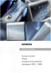
1
SIMATRIX NEO V2
User Manual
Building Technologies
Fire Safety & Security Products
Liefermöglichkeiten und technische Änderungen vorbehalten.
Data and design subject to change without notice. / Supply subject to availability.
© 2008 Copyright by
Siemens Building Technologies
Wir behalten uns alle Rechte an diesem Dokument und an dem in ihm dargestellten Gegenstand vor. Der Empfänger erkennt diese Rechte
an und wird dieses Dokument nicht ohne unsere vorgängige schriftliche Ermächtigung ganz oder teilweise Dritten zugänglich machen oder
außerhalb des Zweckes verwenden, zu dem es ihm übergeben worden ist.
We reserve all rights in this document and in the subject thereof. By acceptance of the document the recipient acknowledges these rights
and undertakes not to publish the document nor the subject thereof in full or in part, nor to make them available to any third party without our
prior express written authorization, nor to use it for any purpose other than for which it was delivered to him.
Contacting us
If you have questions or suggestions regarding the product or this documentation,
please contact our Customer Support Center.
Intranet:
Customer Support Center
Internet:
Worldwide contacts
E-Mail:
[email protected]
Tel.:
+49 89 9221 8000
Copyright
Copyright 2007 © Siemens Fire & Security Products GmbH & Co. oHG.
All rights reserved.
Siemens Fire & Security Products GmbH & Co. oHG confers upon the purchaser
the right to use the software.
It is not permitted to reproduce this manual in whole or in part or translate it into
another language without our written consent.
Contents
1
1.1
1.2
1.2.1
1.2.2
1.2.3
1.2.4
1.2.5
1.3
1.4
Safety .......................................................................................................5
Target readers...........................................................................................5
Work safety information ............................................................................5
Transport...................................................................................................6
Setup.........................................................................................................6
Installation .................................................................................................6
Installation .................................................................................................6
Service and maintenance .........................................................................6
Meaning of the written warning notices ....................................................7
Meaning of the hazard symbols ................................................................7
2
Directives and standards .......................................................................8
3
3.1
3.2
Technical data .........................................................................................9
Video .........................................................................................................9
Control.......................................................................................................9
4
Ordering information ............................................................................11
5
5.1
5.1.1
5.1.1.1
5.1.1.2
5.1.2
5.1.2.1
5.1.2.2
5.1.3
5.1.4
5.1.5
5.1.5.1
5.1.5.2
5.1.5.3
5.1.5.4
5.1.6
5.1.7
5.1.7.1
5.1.7.2
5.2
5.2.1
5.2.2
5.2.3
5.2.4
5.2.5
5.3
5.4
5.4.1
5.4.2
5.5
5.5.1
5.5.2
5.5.3
Operation ...............................................................................................12
Basic program .........................................................................................14
Manual camera image display on a monitor ...........................................14
Using keyboard 1 (master device) ..........................................................14
Using keyboards 2, 3 and 4 ....................................................................14
Starting and stopping a camera image sequence ..................................15
Using keyboard 1 (master device) ..........................................................15
Using keyboards 2, 3 and 4 ....................................................................15
Controlling cameras with pan/tilt and lens drives....................................15
Position control........................................................................................16
Camera image sequences ......................................................................16
Revoking password protection for camera image sequences ................16
Re-establishing password protection ......................................................16
Camera image sequence using keyboard 1 (master device) .................17
Camera image sequence using keyboards 2, 3 and 4 ...........................17
Entering or changing positions................................................................18
Macros ....................................................................................................18
Recording a macro..................................................................................18
Executing a macro ..................................................................................18
Alarm program 2 (factory setting) ...........................................................19
Alarm processing in alarm program 2 .....................................................20
Revoking password protection for detection group activation ................21
Re-establishing password protection ......................................................21
Activating detection groups.....................................................................21
Deactivating detection groups.................................................................23
Switching system time to summer/normal time settings .........................25
Resetting and initial system boot ............................................................25
System reset ...........................................................................................25
Rebooting the system (to alarm program 2 factory settings)..................25
Network configuration and firmware update ...........................................26
Configuring the network ..........................................................................26
Updating the firmware.............................................................................27
Activating write protection for network configuration and firmware
update .....................................................................................................28
3
Siemens Building Technologies
Fire Safety & Security Products
04.2008
6
Maintenance...........................................................................................29
7
Disposal .................................................................................................30
8
8.1
8.2
Appendix ................................................................................................31
Glossary ..................................................................................................31
Summary of basic and alarm program features......................................32
4
Siemens Building Technologies
Fire Safety & Security Products
04.2008
Safety
1
Safety
1.1
Target readers
The instructions in this document are designed only for the following target
readers:
1.2
Reader group
Qualification
Activity
Condition of the
product
Operator
Has read and understood
the instructions in the
documentation regarding
operation. No particular
basic training is required,
although some instruction
by technical specialists may
be necessary.
Performs only the
procedures for proper
operation of the product,
device or system.
The product is installed
and set up.
Service personnel
Technical training for
building or electrical
installations.
Checks the product at
regular intervals to
ensure that it is in good
working order, services
the product and repairs it.
Product already in use
and requiring servicing.
Work safety information
z Read the general safety precautions before operating the device.
z Follow all warnings and instructions marked on the device.
z Keep this document for reference.
z Always pass this document on together with the product.
z Any national or local safety standards or laws that apply to the development,
design, installation, operation or disposal of a product must be adhered to in
addition to the instructions in the product documentation.
Liability claim
z Do not connect the device if it is damaged or any parts are missing.
z Do not make any changes or modifications to the device unless they are
expressly mentioned in this manual and have been approved by the
manufacturer. Unauthorized changes will void the user's authority to operate the
equipment.
z Use only spare parts and accessories approved by the manufacturer.
Radio interference with other devices in the environment
z This is a Class A device. This equipment may cause radio interference in a
residential installation. In this case the user is encouraged to perform
appropriate measures to correct the interference.
5
Siemens Building Technologies
Fire Safety & Security Products
04.2008
Safety
1.2.1
Transport
Damage during transport
z Keep the packaging material for future transportation.
z Do not expose the device to mechanical vibrations or shocks.
1.2.2
Setup
Damage due to unsuitable mounting location
z Observe the environmental requirements recommended by the manufacturer.
z Do not operate the device close to sources of powerful electromagnetic
radiation.
z Protect the device against moisture.
z Do not operate the device in excessively dusty places.
z Do not expose the device to mechanical vibrations or shocks.
Liability claim
z For reasons of electromagnetic compatibility RS232, USB, audio in/out and
power supply cables must not exceed 3 meters length.
Damage to the device due to overvoltage
z Connect the device only to power sources with the specified voltage. Voltage
supply requirements can be found on the power supply unit/type label.
1.2.3
Installation
Cable damage due to mechanical load
z When connecting the cables, do not apply tensile force and make sure not to
bend or damage them.
1.2.4
Installation
Data loss after update
z The device is designed to work with TN power system only.
z Only use power supply cables that have been approved in your country.
1.2.5
Service and maintenance
Risk of electric shock during maintenance
z Always disconnect the power cable and other cables from the device before
performing maintenance.
Danger of electrical shock while cleaning the device
z Disconnect the device from the mains supply before cleaning it.
z Do not use liquid cleaners or sprays that contain alcohol, spirit or ammonia.
6
Siemens Building Technologies
Fire Safety & Security Products
04.2008
Safety
1.3
Meaning of the written warning notices
The severity of a hazard is indicated by the following written warning notices.
Signal word
Type of risk
DANGER
Dangerous situation
Death or severe bodily injury may result.
CAUTION
Dangerous situation
Severe bodily injury may result.
NOTE
Technical or operating information
Disregarding this information may lead to damage to the product or property in
the product’s vicinity.
1.4
Meaning of the hazard symbols
The nature of the hazard is indicated by icons.
Dangerous situation
Tips and information
Important operating step or action
For example: the system, components or controls must be at zero potential.
7
Siemens Building Technologies
Fire Safety & Security Products
04.2008
Directives and standards
2
Directives and standards
This product complies with the requirements of the European Directives
2004/108/EEC “Directive of Electromagnetic Compatibility” and 2006/95/EEC “Low
Voltage Directive”. The EU declaration of conformity is available to the responsible
agencies at:
Siemens Building Technologies
Fire & Security Products GmbH & Co. oHG
76181 Karlsruhe
European Directive 2004/108/EEC "Electromagnetic Compatibility"
Compliance with the European Directive 2004/108/EEC has been proven by
testing according to the following standards:
Electromagnetic emission
EN 55022 Class A
Electromagnetic
compatibility
EN 50130-4
European Directive 2006/95/EEC „Low-Voltage Directive”
Compliance with the European Directive 2006/95/EEC has been proven by testing
according to the following standards:
Safety:
EN 60950-1
8
Siemens Building Technologies
Fire Safety & Security Products
04.2008
Technical data
3
Technical data
3.1
Video
Video inputs
BNC sockets
Uss=1V video, 75 Ω, with plug-in jumpers and switchable
terminations
Video outputs
BNC sockets
Uss=1V video, 75 Ω
Video signal failure recognition
Vertical synchronisation pulse monitoring
Text overlay
Complete IBM character set,
internal synchronisation,
character display: white background, black frame
Field size:
12 text lines of 24 characters each
Character height:
18 screen lines
Cross-talk attenuation
≥ 56 dB at 5 MHz
Differential amplification
≤ 1%
Differential phase
≤ 0,6°
Frequency response characteristic
-0.5 dB at 6 MHz
Switching point change-over time after
command signal reception at the video matrix
80 ms (typical), 200 ms (max.)
3.2
Control
Control computer
6 RISC-Controller
Interfaces for
Progr.-PC, IVM-NT, TELEMAT, SIPASS, LMS
3 x V.24 interfaces
Baud rate:
1200 – 19,200 bit/s
Connection:
3 x 9-pin Sub-D connectors
Keyboards
8 x TTY(20mA) interfaces with built-in electrical supply for 8
keyboards, (supply max. 800mA total)
Cable length:
up to 2 km, wire diameter 0.8 mm
Baud rate:
1200 – 9600 bit/s
Connection:
8 x RJ12 sockets
PTZ control (CDC)
16 x CDC(20mA) interfaces
Cable length:
up to 2 km, wire diameter 0.8 mm
Baud rate:
1200 – 9600 bit/s
Control of Telemetrie devices
4 x RS422/RS485-Ports;
Protocols:
CCDA, SCU, SIVIS, PELCO-D
Connection:
4 x RJ11-Buchse / Port
Sensor groups
Alarm sensors, alarm contacts
32 x alarm inputs for detection groups
Cable length:
up to 10 m
Connection:
2 x 37-pin Sub-D socket
9
Siemens Building Technologies
Fire Safety & Security Products
04.2008
Technical data
Control computer
6 RISC-Controller
Video recorder, Picture storage
8 control outputs (open-collector); max. 30 V, max. 50 mA
Relay with 2 voltage-free change-over contacts for collective alarm
signalling; max. 48 V, 250 mA;
Connection:
1 x 25-pin Sub-D socket
LAN / Ethernet
8P8C modular plug (RJ45) with 10/100 Base-T Ethernet port for
configuration via network, connection of LAN components, status
request via integrated Web server
Power supply
115 – 230 V AC, tolerance: +10%/-15%
Switching power supply, 50 to 60 Hz
The mains socket is fitted with two microfuses (1.6 A slow-blow)
Power requirement
Maximum system size: 55 VA
per 16 input coupler PCB: 1.4 VA
per 8 output coupler PCB: 2.8 VA
Operating temperature
5 to 45 °C
Relative humidity
30 to 85 %, non-condensing
Construction
19 inch chassis, 6 HU
Dimensions (w x h x d, chassis without 19”mount)
441 x 266 x 217 mm
10
Siemens Building Technologies
Fire Safety & Security Products
04.2008
Ordering information
4
Ordering information
Order reference
Short
designation
Product
Weight
(approx.
In kg)
2GF2211-8AA
SIMNEO-168
SIMATRIX NEO 168, complete, 19" base module, 6 HU, PAL model*, incl. CPU,
16 video inputs, 8 video outputs, 32 alarm inputs
6.5
*Note: NTSC model available on request
Extension options
2GF2211-8AB
SIMNEO-EXT
SIMATRIX NEO 19" extension bay, 6 HU,
incl. 32 video inputs, 16 video outputs
6.3
2GF2211-8CA
SIMNEO-IM
Video input module, 16 extra video inputs
0.24
2GF2211-8DA
SIMNEO-OM
Video output module with text overlay,
upgrade for the base module with 8 extra video outputs
0.03
2GF2211-8DB
SIMNEO-SOM
Video output module without text overlay,
8 extra video output upgrade for the extension bay
0.03
2GF2211-8EA
SIMNEO-A128
Alarm box, 128 alarm inputs, 19" module, 1 HU
2.50
2GF2400-8EA
CKA 3210
Keyboard without joystick
0.9
2GF2400-8EB
CKA 4810
Keyboard with joystick
1.05
2GF2400-8DA
SUT 48
Keyboard with keys (customer-specified lettering) and joystick
1.2
2GF1800-8BE
PSU230-12
Plug-in power supply unit
for the external power supply of the keyboards,
230 V, 50 Hz/12 V DC, 640 mA,
for interior use, complete with 2 m DC cable with open, tinned ends
0.53
2GF2207-8AE
2GF2207-8AF
2GF2207-8AG
SIM-CC3
SIM-CC7
SIM-CC10
2GF2208-8AG
SIM-PC
Accessories
- 3 m connection cable for keyboard
- 7 m connection cable for keyboard
- 10 m connection cable for keyboard
Connection cable for external computers with 9-pin AT connector, 2 m long, for
programming the video matrix and loading the alarm program.
2GF5505-8BA
CAC0101
TTY/TTL interface converter
0.1
S24245-F5046-A1
CAC0103
DOME converter
0.6
2GF5505-8AK
TTY1X8
TTY distributor, 8 port
0.2
S24245-B5015-A1
CDC0501
PTZ drive control unit for pan/tilt camera heads without presets
2.85
S24245-B5017-A1
CDC0502
PTZ drive control unit for pan/tilt camera heads with position memory for 64 presets
2.85
2GF1708-8EA
CDD2410
PTZ drive
7.0
11
Siemens Building Technologies
Fire Safety & Security Products
04.2008
Operation
5
Operation
All the set-up profiles supplied are suitable for the following system configurations:
– IVM-NT systems (on COM2, COM3, COM4)
– 4 keyboards
– 48 Cameras with pan/tilt and lens drives
(video inputs 1-48)
– 48 CDCs with position control
– 32 Detection groups
Fig. 1
Keyboard 1 (key layout SUT 48; monitors 1 to 4)
Fig. 2
Keyboard 1 (key layout CKAxx; monitors 1 to 4)
The labels should be removed from any keys that are not required for keyboards 2
to 4.
12
Siemens Building Technologies
Fire Safety & Security Products
04.2008
Operation
Fig. 3
Keyboard 2 (key layout SUT 48; identical to keyboards 3 to 4; each
device controls a single monitor)
Fig. 4
Keyboard 2 (key layout CKAxx; identical to keyboards 3 to 4; each
device controls a single monitor)
13
Siemens Building Technologies
Fire Safety & Security Products
04.2008
Operation
5.1
Basic program
No alarm processing takes place in the basic program.
The description of the basic program below also applies to alarm program 2.
The keyboard has a 10-digit keypad and a function pad with 22 grey keys.
Number sequences of up to 3 digits can be entered using the digit keypad.
All the functions are entered using one of the grey function keys.
5.1.1
Manual camera image display on a monitor
5.1.1.1 Using keyboard 1 (master device)
A set key sequence entered via keyboard 1 allows the image from each camera to
be switched to each monitor.
Key sequence:
1.
Enter the camera number using the digit keys(X).
Î
2.
The word Entry and the entered camera number will appear on monitor 1.
Select the monitor of your choice by keying MON Y
(e.g. MON 2 for monitor 2).
Î
The selected monitor will display the image of the selected camera.
The display on monitor 1 will go blank. If no monitor key is pressed, the
display on monitor 1 will go blank after about 5 seconds.
5.1.1.2 Using keyboards 2, 3 and 4
When using keyboards 2, 3 and 4, it is only possible to display the image from the
chosen camera on the monitor that has been allocated to the keyboard in question.
Key sequence:
1.
Enter the camera number using the digit keys(X).
Î
2.
The word Entry and the entered camera number will appear on monitor 1.
Key in MON Y.
14
Siemens Building Technologies
Fire Safety & Security Products
04.2008
Operation
5.1.2
Starting and stopping a camera image sequence
5.1.2.1 Using keyboard 1 (master device)
Key sequence:
3.
Start the desired picture cycle by pressing a SEQ key, e.g. SEQ 2.
4.
Stop the sequence by manually switching a camera to this monitor or by
pressing the associated monitor key, e.g. MON 2.
Î
The monitor screen will go blank.
5.1.2.2 Using keyboards 2, 3 and 4
When using keyboards 2, 3 and 4, it is only possible to start a camera sequence
that has been allocated to the keyboard in question.
Key sequence:
1.
Start the picture cycle using the SEQ key. In the case of keyboard 2 this
would be SEQ 2.
2.
Stop the sequence by manually switching a camera to this monitor or by
pressing the monitor key, e.g. MON 2.
Î
5.1.3
The monitor screen will go blank.
Controlling cameras with pan/tilt and lens drives
It is possible to remotely control cameras with pan/tilt and lens drives manually.
This always applies to the camera that was last selected using the keyboard.
Key sequence:
1.
User the ← → ↑ ↓ keys or the joystick to tilt the camera horizontally or
vertically.
2.
Adjust the focal length using the Z+ and Z– keys
3.
Use the ∞ and 0 keys to adjust focus.
15
Siemens Building Technologies
Fire Safety & Security Products
04.2008
Operation
5.1.4
Position control
If the camera head drive incorporates a position control facility (e.g. CDC0402 or
SCU-302), the camera can be moved to preset positions. In the case of keyboard
1, this applies to the camera that is currently switched to monitor 1. In the case of
the other keyboards, this always applies to the camera that was last switched to
monitor in question.
Key sequence:
5.1.5
1.
Enter the number of the desired position using the digit keys(X).
2.
Press P.
Camera image sequences
A password is required to set or change camera sequences (factory setting is
1234, refer to the programming manual to change this setting). The password must
be entered to enable storing or changing of camera image sequences. When
finished, you must re-establish password protection.
5.1.5.1 Revoking password protection for camera image sequences
Key sequence:
1.
Enter digit 1 and 2 of the password.
2.
Press the Alarm ON key
3.
Enter digit 3 and 4 of the password.
4.
Press the Alarm ON key.
Î
5.
The monitor will display the following instruction: Password
You can now enter new sequences or make changes.
5.1.5.2 Re-establishing password protection
When you have finished entering a new sequence or making changes, you must
re-establish password protection to prevent unauthorised intervention.
Key sequence:
– Enter 254
6.
Press the Alarm ON key.
Î
The on-screen instruction, Password, disappears.
16
Siemens Building Technologies
Fire Safety & Security Products
04.2008
Operation
5.1.5.3 Camera image sequence using keyboard 1 (master device)
Camera image sequences for monitors 1 to 4 can be stored using keyboard 1.
Key sequence:
1.
Enter the camera number using the digit keys (X).
2.
Select the monitor of your choice by keying MON Y (e.g. MON 2 for monitor
2).
Î
The selected monitor will display the image of the selected camera.
3.
Enter the number of the monitor (Y) where you want to display the camera
image sequence.
4.
Add the camera to the chosen camera image sequence by keying SEQ + C.
Deleting a camera from a camera image sequence
Key sequence:
1.
Enter the camera number using the digit keys (X).
2.
Select the monitor where you want to display the camera image sequence by
keying MON Y (e.g. MON 2 for monitor 2).
3.
Delete the camera from the chosen sequence by keying SEQ - C.
5.1.5.4 Camera image sequence using keyboards 2, 3 and 4
When using keyboards 2, 3, 4, it is only possible to enter or change a camera
image sequence for the current monitor.
Key sequence:
1.
Enter the camera number using the digit keys (X).
2.
Key in MON Y (e.g. MON 2 for monitor 2).
Î
The camera image from the chosen camera appears on the monitor.
3.
Enter the number of the monitor (Y), to which the keyboard has been
allocated
(e.g. 2 for monitor 2).
4.
Add the camera to the chosen camera image sequence using the SEQ + key
Deleting a camera from a camera image sequence
Key sequence:
1.
Enter the camera number using the digit keys(X).
2.
Key in MON Y (e.g. MON 2 for monitor 2).
3.
Delete the camera from the chosen sequence using the SEQ - key.
17
Siemens Building Technologies
Fire Safety & Security Products
04.2008
Operation
5.1.6
Entering or changing positions
Position control of the camera panning drives and lens drives is only possible if
each panning drive and lens drive has been initialised during initial system set-up
(see programming manual).
The keyboards can be used as follows to set, change and store positions for
cameras with pan/tilt drives and with lens drives:
– Keyboard 1: for the camera switched to monitor 1
– Keyboards 2, 3 and 4: for the camera that was last switched to the monitor
Key sequence:
1.
Move the panning drive and lens drive of the selected camera to the desired
position by pressing the ← → ↑ ↓ Z– Z+ 0 ∞ keys.
2.
Enter the position number using the digit keys (Z).
3.
Press S to store the position.
This saves the position for the corresponding camera head drive to memory,
allowing it to be retrieved whenever required (see chapter 3).
5.1.7
Macros
The SIMATRIX NEO can store four macros, which can then be recorded using a
keyboard. The stored macros can be triggered through keyboard operation, by a
time threshold or an alarm contact. Macros allow automation of complex special
functions.
Commands for camera head drives cannot be used in macros.
Please refer to the description of the configuration program for more details relating
to macro programming.
5.1.7.1 Recording a macro
For SIMATRIX NEO V2, the macros are defined during configuration.
Up to 32 macros with 48 functions each can be defined.
5.1.7.2 Executing a macro
– Depending on the way your have configured macro operation, either press the
predefined macro hotkey or enter the macro number and press Macro
18
Siemens Building Technologies
Fire Safety & Security Products
04.2008
Operation
5.2
Alarm program 2 (factory setting)
The same operating options offered by the basic program are also available in the alarm programs.
Alarm program 2 also offers the operating options that have been described for the
basic program. Alarm processing is offered as an addition feature. A detection
group feature is included for each camera input.
This program allows sequencing of 48 cameras, which are each identified as the
next in sequence camera relative to a previous camera
Example:
– Camera that triggers the alarm: camera 15
– next in sequence camera: camera 14.
The configuration details must be changed as indicated in the programming
manual if less than 48 cameras are installed or other sequences are required.
Detection groups can be activated and deactivated using a password.
The detection group table can be retrieved at any time by pressing the Alarm ON
key.
The table disappears when the Alarm ON key is pressed again.
If the SIMATRIX NEO V2 has been installed in combination with the Siemens
TELEMAT video alarm system, the zone from which the alarm originates will be
highlighted in the alarm image when an alarm is triggered. Acknowledging an
alarm will then also reset the TELEMAT system.
19
Siemens Building Technologies
Fire Safety & Security Products
04.2008
Operation
5.2.1
Alarm processing in alarm program 2
Alarm can be processed as follows:
– When an alarm is triggered, the alarm image (camera image of the zone from
which the alarm originates) appears on monitors 1 and 4 along with the text
ALARM!.
– The alarm can be acknowledged (turned off) by keying MON 1.
The original images will now appear on the monitors.
– if a second alarm is triggered before the first alarm can be acknowledged, the
second alarm image will appear on monitor 2.
– Each additional alarm image will overwrite one of the alarm images on display,
so that monitors 1 and 2 always display the most recent two alarm images.
– If two or more alarm images are active simultaneously, they will all appear as an
alarm image sequence on monitor 4.
Fig. 5
Display of two alarm images
AB
Alarm image
AB1-AB2
Alarm image display on monitors 1 and 2
Kx S
Selected camera image sequence on monitor 3
A
Alarm image sequence on monitor 4
VTR: 1
Video recorder for gap-free alarm image recording from output 4
– The alarm displays on monitors 1 and 2 can be acknowledged. The oldest, next
in-sequence image will then appear on the monitor where the image has just
been acknowledged. When this alarm image is acknowledged, the next oldest
alarm image appears, etc.
– Monitor 3 is still available to switch cameras manually or to play the automatic
image sequence.
– A video recorder connected to output 4 starts up automatically at the first alarm
signal.
It records the images that appear on monitor 4.
– The recorder stops when the last alarm is acknowledged or switches to the
preset long-term recording setting.
20
Siemens Building Technologies
Fire Safety & Security Products
04.2008
Operation
5.2.2
Revoking password protection for detection group activation
Key sequence:
1.
Enter digit 1 and 2 of the password.
2.
Press the Alarm ON key
3.
Enter digit 3 and 4 of the password.
4.
Press the Alarm ON key.
Î
5.
5.2.3
The monitor will display the following instruction: Password
You can now make changes.
Re-establishing password protection
When you have finished making changes, you must re-establish password
protection to prevent unauthorised intervention.
Key sequence:
6.
Enter 254
7.
Press the Alarm ON key
Î
5.2.4
The on-screen instruction, Password, disappears.
Activating detection groups
Key sequence:
1.
Press the Alarm ON key
Î
The following alarm input table appears on the monitor (example):
Fig. 6
Detection groups table
21
Siemens Building Technologies
Fire Safety & Security Products
04.2008
Operation
Key sequence:
2.
Enter the number of the detection group that you want to activate.
Î
3.
The word Entry and the entered number will appear on the monitor.
Press the Alarm ON key.
The monitor displays the table with a plus sign at the side of the active alarm
input.
Activating all alarm inputs simultaneously
Î
1.
Enter 255 to simultaneously activate all the alarm inputs
2.
Press the Alarm ON key.
Î
The following table appears on the monitor:
Fig. 7
Detection groups table: all groups activated
22
Siemens Building Technologies
Fire Safety & Security Products
04.2008
Operation
5.2.5
Deactivating detection groups
Key sequence:
1.
Press the Alarm ON key.
Î
The following alarm input table appears on the monitor (example):
Fig. 8
Detection groups table
Key sequence:
2.
Enter the number of the detection group that you want to deactivate.
Î
3.
The word Entry and the entered number will appear on the monitor.
Press the Alarm OFF key.
Î
The monitor displays the table with a minus sign at the side of the activated
alarm input.
23
Siemens Building Technologies
Fire Safety & Security Products
04.2008
Operation
Deactivating all alarm inputs simultaneously
1.
Enter 255 and press the Alarm OFF key.
Î
The following table appears on the monitor:
Fig. 9
Detection groups table: all groups deactivated (see programming
manual)
24
Siemens Building Technologies
Fire Safety & Security Products
04.2008
Operation
5.3
Switching system time to summer/normal time settings
The system time in the SIMATRIX NEO V2 can be switched to summer time, or
switched back to normal time. Repeating the key sequence switches between
summer and normal time
Key sequence:
You can check that the setting has been changed successfully in the camera text
display.
Alternatively, you can use the configuration program to set the system time in the
PC connected to the SIMATRIX NEO V2 as the system time in the video matrix
unit.
5.4
Resetting and initial system boot
Should the system become inoperable due to programming errors, it can either be
reset or rebooted to the delivery configuration, in which alarm program 2 is active.
5.4.1
System reset
Proceed as follows to reset the system:
1.
Press the red Reset button on the rear of the SIMATRIX NEO V2 for a few
seconds, until the message waiting for CPU appears in the front display.
Î
5.4.2
Resetting has the same effect as pulling out the mains plug and then turning
the device back on.
Rebooting the system (to alarm program 2 factory settings)
1.
Press in and hold down the green Default button on the back of the
SIMATRIX NEO V2.
2.
Next, briefly press the red Reset button while keeping the green Default
button depressed.
Î
3.
The text waiting for CPU, followed after a few seconds by defaults loaded
will appear on the front display.
Release the green Default button.
Î
You have successfully rebooted the system.
Caution
Next, reset the system again using the red Reset button, or switch off by pulling
out the mains plug and turn the device back on.
25
Siemens Building Technologies
Fire Safety & Security Products
04.2008
Operation
5.5
Network configuration and firmware update
5.5.1
Configuring the network
You can configure the network parameters of SIMATRIX NEO V2 and of the LAN
control units..
To configure the network parameters:
4.
Open the file VMLANcfg.exe.
Î
The window that opens provides the buttons Automatic Search and Manual
Search, as well as a list of all the SIMATRIX clients in the network. The
appearance of the search area partly depends on the net mask settings on
the configuration PC used.
The Manual Search button is needed only if the client to be configured or updated is not within the
local network and can only be reached via a router or gateway.
5.
Click on Automatic Search.
Î
6.
All the SIMATRIX clients that are available in the local network will be
displayed in the list.
Click on the desired client in the list.
Î
The display window is expanded to a second pane showing the network
configuration of the selected client, which can now be edited.
26
Siemens Building Technologies
Fire Safety & Security Products
04.2008
Operation
5.5.2
7.
To download the changes you have made to the client, click Update client.
8.
To terminate the connection without making any changes, click Abort
Connection.
Updating the firmware
Prerequisite:
z The client supports a firmware update feature.
Updating the firmware
1.
Open the file VMLANcfg.exe.
2.
Click on the desired client in the list.
3.
Click on Firmware Update.
Î
4.
The update window opens.
Click on Browse to load the update file.
27
Siemens Building Technologies
Fire Safety & Security Products
04.2008
Operation
Î
5.
Once the file has been loaded, the content and version of the update file are
displayed in the Firmware Info window.
Click on Start firmware update.
Î
The update is started; it will take about 30 seconds, and the progress is
displayed by a progress bar. When the update is completed successfully, a
message will appear on the display. This message will remain on the display
until one of the menu buttons is pressed.
Network configuration and firmware update will not be possible when the write protection mode of the
SIMATRIX client is activated (see Section 5.5.3: Activating write protection for network configuration
and firmware update).
5.5.3
Activating write protection for network configuration and firmware update
A write protection can be activated to protect the network configuration settings
and the firmware of SIMATRIX NEO V2 against unauthorized access.
Activate write protection
1.
Press the green "Default" button (next to the "Reset" button at the rear of
SIMATRIX NEO V2, Section 5.4.1) for approx. 5 to 10 seconds.
Î
When any of these buttons is pressed, a corresponding message will appear
on the display. This message will be deleted when any of the menu buttons is
pressed.
Deactivate write protection
1.
Press the green "Default" button (next to the "Reset" button at the rear of
SIMATRIX NEO V2, Section 5.4.1) for approx. 5 to 10 seconds.
Î
When any of these buttons is pressed, a corresponding message will appear
on the display. This message will be deleted when any of the menu buttons is
pressed.
In the delivery configuration the write protection is not activated, which means that the network
configuration settings can be changed and a firmware update be made via the network at any time.
28
Siemens Building Technologies
Fire Safety & Security Products
04.2008
Maintenance
6
Maintenance
Danger
When in operation, a number of components in this device are electrically live.
Inexpert handling or operation of this device could therefore result in death,
severe bodily harm or damage to property. The device may only be serviced
and maintained by suitably qualified personnel.
The device must be isolated from the electrical supply before work starts on it.
In the event of breakdown, we recommend you contact your local Siemens branch
for service and support.
The mains supply voltages and secondary voltages are fused as follows:
Electrical supply
115 - 230 V AC (+10%/-15%), 50/60 Hz, 55 VA max.
Fuses
2 x T 1.6 A 250 V,
29
Siemens Building Technologies
Fire Safety & Security Products
04.2008
Disposal
7
Disposal
All electrical and electronic products should be disposed of separately from the
municipal waste stream via designated collection facilities appointed by the
government or the local authorities.
If this symbol showing a crossed-out trash can is displayed on a product, that
product is subject to the EU Directive 2002/96/EC.
The correct disposal and separate collection of your old appliance will help
prevent potential negative consequences for the environment and human health.
It is a precondition for reuse and recycling of used electrical and electronic
equipment. For more detailed information about disposal of your old appliance,
please contact your city office, waste disposal service or the shop where you
purchased the product.
30
Siemens Building Technologies
Fire Safety & Security Products
04.2008
Appendix
8
Appendix
8.1
Glossary
Alarm image switching
An alarm image appears on the monitor until it is acknowledged
Alarm image sequence
All as yet acknowledged alarm images are shown repeatedly in sequence on a monitor
Alarm sequence
See alarm image sequence
Autoreset
The alarm image disappears from the monitor, as soon as the alarm signal resets. See also manual
reset and stack reset
Image sequence
Images from several cameras can be switched to a monitor in sequence. The image sequence can
be started or stopped by a key on the keyboard. Alternatively, the system can be configured to
display preset camera images upon start-up.
Dome cameras
Ceiling-mounted, rapid-response, remote control camera with a lens drive system. Housed in a
glass dome.
CCDA
Siemens dome cameras
CCTV
Closed Circuit Television, independent television system in a delimited area
External detection group
Group switching
A key on the keyboard is used to switch the images from a camera group to a group of monitors.
IVM-NT
Integrated Video Management System
LMS
Location planning system
Manual reset
As opposed to autoreset. The alarm image remains on display when the alarm signal resets. Alarm
events that have already been displayed are overwritten without being stored in memory. See also
autoreset and stack reset
Pelco D
3rd party supply dome camera
Serial switching, stepped
switching
When several alarm images are switched simultaneously, the most recent alarm image is displayed
on all monitors in turn. This only applies to monitors that have been configured for alarm image
switching.
transfer switching
The most recent alarm image is always displayed on the primary monitor (master monitor) in the
monitor group. When several alarm images are displayed simultaneously, the less recent images
are transferred to the other monitors.
SCU protocol
Protocol for controlling telemetry devices
SISTORE NT
Image storage system
Sivis Minidome
Siemens dome cameras
Stack alarm
New alarm images overwrite old alarm images (manual and autoreset)
Stack reset
As manual reset, but the alarm events are saved to memory before being overwritten by new alarm
events. See also autoreset and manual reset
SysLink
Serial system bus. Allows connection of the extension bay and alarm box
TELEMAT MD/MTD
Video sensor that recognises motion in the camera image
Time-lapse operation
Long-term recording of individual images
31
Siemens Building Technologies
Fire Safety & Security Products
04.2008
IVM-NT operating stations 1 to 3
TELEMAT
Cameras1 to 48
Camera head controls 1 to 48
Monitors 1 to 4
Keyboards 1 to 4
Alarm program 1
Deviation from the factory setting
Fire Safety & Security Products
Siemens Building Technologies
32
Factory settings
yes
on monitor 1
monitor 2 (neighbouring
camera) is also released
all as yet unacknowledged
alarm images on monitor 4
no
no
no
no
yes
04.2008
yes
on monitor 1
monitor 2 (neighbouring
camera) is also released
all as yet unacknowledged
alarm images on monitor 4
yes
yes
on monitors 1 and 2
next image on first free monitor
yes
no
4
per camera
configured for external
detector groups(48)
2
no
serial switching
yes
monitor 2
4
per camera
configured for external detector
groups(48)
4
using keyboard 1
using keyboards 2, 3 and 4
on monitors 1 to 4
on all monitors
on a maximum of 8 monitors
on all monitors
48 cameras via a single
operating station
pro CDC
not recommended for IVM-NT
not recommended for
TELEMAT
1 to 48
1 to 48
1 to 4
1 to 4
Alarm program 6
yes
yes
monitor 2
no
1
per camera
configured for external
detector groups(48)
1
using keyboard 1
using keyboards 2, 3 and 4
on monitors 1 to 4
on all monitors
on a maximum of 8 monitors
on all monitors
48 cameras via a single operating
station
pro CDC
not recommended for IVM-NT
not recommended for TELEMAT
1 to 48
1 to 48
1 to 4
1 to 4
Alarm program 3
alarm image 1 on monitor 1
alarm image 2 on monitor 2
alarm image 3 on monitor 1 etc.
in turn on monitors 1 and 2
1
2
Alarm image sequence all as yet unacknowledged alarm all as yet unacknowledged alarm
images on monitor 4
images on monitor 4
Switching method serial switching
(transfer/serial switching)
New alarm images overwrite older no
images
Mandatory alarm image yes
acknowledgement on monitors 1 and 2
next image on first free monitor
Alarm image display alarm image 1 on monitor 1
alarm image 2 on monitor 2
.
Most recent alarm image display in turn on monitors 1 and 2
(transfer/serial switching)
per camera
configured for external detector
groups(48)
2
per camera
configured for external detector
groups(48)
2
using keyboard 1
using keyboards 2, 3 and 4
on monitors 1 to 4
on all monitors
on a maximum of 8 monitors
on all monitors
48 cameras via a single
operating station
pro CDC
1 to 3
1 to 48
1 to 48
1 to 4
1 to 4
Alarm program 5
yes
monitor 2
monitor 4
alarm image 1 on monitor 1
alarm image 1 on monitor 1 most recent alarm image (highest most recentalarm image 1 on
and, until acknowledged, on
number) on monitor 1
monitor 1
monitor 4.
next most recent on monitors 2 to 4 alarm image 2 on monitor 3
both images simultaneously on both images simultaneously last in first out (LIFO)
last in first out (LIFO)
monitor 1 and monitor 2
on monitor 1 and monitor 2 on monitor 1
most recent on monitor 1
previous image on monitor 3
previous image on monitor 3
serial switching
serial switching
transfer switching
transfer switching
using keyboard 1
using keyboards 2, 3 and 4
on monitors 1 to 4
on all monitors
on a maximum of 8 monitors
on all monitors
48 cameras via a single
operating station
pro CDC
1 to 3
1 to 48
1 to 48
1 to 4
1 to 4
Alarm program 4
using keyboard 1
using keyboards 2, 3 and 4
on monitors 1 to 4
on all monitors
on a maximum of 8 monitors
on all monitors
48 cameras via a single operating
station
pro CDC
1 to 4
1 to 3
1 to 48
1 to 48
1 to 4
Alarm program 2
Factory setting
Summary of basic and alarm program features
Basic functions (available without alarm processing)
Central dial-up using keyboard 1
Decentral dial-up using keyboards 2, 3 and 4
Monitor sequencing on monitors 1 to 4
Camera label on all monitors
Date, time on a maximum of 8 monitors
Camera breakdown signal on all monitors
Camera and lens control using 48 cameras via a single operating
CDCs station
Camera position control per CDC
Alarm processing functions
Detector groups per camera
Detector groups input configuration configured for external detector
groups(48)
Max. no. of alarm images 2
(simultaneous display)
Max. no. of alarm events 2
(simultaneous display)
Neighbouring camera display no
Devices
Features
8.2
Appendix
Issued by
Siemens Building Technologies
Fire & Security Products GmbH & Co. oHG
D-76181 Karlsruhe
www.buildingtechnologies.siemens.com
Document no.
A6V10204880
Edition
22.04.2008
© 2008 Copyright by
Siemens Building Technologies
Data and design subject to change without notice.
Supply subject to availability.
Printed in the Federal Republic of Germany
on environment-friendly chlorine-free paper.