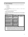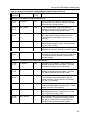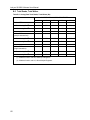
1
SLX200 Software User Manual
isoLynx™ SLX200 Software User Manual
isoLynx™ SLX200 Software User Manual
MA1025 Rev. D—November 2006
The information in this manual has been checked carefully and is believed to be accurate; however,
Dataforth assumes no responsibility for possible inaccuracies or omissions. Specifications are
subject to change without notice.
© 2005-2006 Dataforth Corporation. All rights reserved.
isoLynx is a trademark of Dataforth Corporation.
IBM, IBM PC, XT, AT, and PS/2 are trademarks or registered trademarks of
International Business Machine Corporation.
Microsoft, MS-DOS, Windows, Windows NT, Visual Studio, Visual C++, and Visual BASIC are
trademarks or registered trademarks of Microsoft Corporation.
National Instruments™ and LabVIEW™ are trademarks or registered trademarks of
National Instruments Corporation.
i
isoLynx SLX200 Software User Manual
ii
Table of Contents
1.
INTRODUCTION .........................................................................................................................................1
1.1. RELATED DOCUMENTS ............................................................................................... 1
1.2. DOCUMENT CONVENTIONS ......................................................................................... 1
2.
DEVICE OPERATION .................................................................................................................................3
2.1. DEVICE CONFIGURATION ............................................................................................ 3
2.2. ANALOG DATA ........................................................................................................... 3
2.2.1.
2.2.2.
Reading Analog Data.................................................................................................................4
Writing Analog Data..................................................................................................................5
2.3. DIGITAL DATA ............................................................................................................ 6
2.3.1.
2.3.2.
3.
Reading Digital Data .................................................................................................................6
Writing Digital Data ..................................................................................................................6
ISOLYNX SLX200 COMMUNICATION INTERFACE.............................................................................7
3.1. MODBUS PROTOCOL ................................................................................................... 7
3.1.1.
3.1.2.
3.1.3.
3.1.4.
3.1.5.
Modbus RTU .............................................................................................................................7
Modbus TCP ..............................................................................................................................7
Modbus Function Codes ............................................................................................................7
Modbus Addresses.....................................................................................................................8
Modbus Exceptions....................................................................................................................8
3.2. CHANGING THE COMMUNICATION PROTOCOL ............................................................ 9
3.3. RESETTING COMMUNICATION PARAMETERS TO FACTORY DEFAULT VALUES ............ 9
3.4. MODBUS RTU PARAMETERS .................................................................................... 10
3.4.1.
Modbus RTU Parameter Registers ..........................................................................................11
3.5. MODBUS TCP PARAMETERS ..................................................................................... 12
3.5.1.
4.
Modbus TCP Parameter Registers ...........................................................................................13
ANALOG CHANNEL CONFIGURATION...............................................................................................15
4.1. ANALOG CHANNEL STATES ...................................................................................... 16
4.1.1.
Analog Channel State Registers...............................................................................................16
4.2. ANALOG CHANNEL AVERAGE WEIGHTS ................................................................... 17
4.2.1.
Analog Channel Average Weight Registers ............................................................................17
4.3. ANALOG CHANNEL DEFAULT OUTPUTS.................................................................... 18
4.3.1.
5.
Analog Channel Default Output Registers...............................................................................18
DIGITAL CHANNEL CONFIGURATION ...............................................................................................19
5.1. DIGITAL CHANNEL STATES ....................................................................................... 20
5.1.1.
Digital Channel State Registers ...............................................................................................20
5.2. DIGITAL OUTPUT DEFAULT OUTPUTS ....................................................................... 21
5.2.1.
6.
Digital Channel Default Output Registers ...............................................................................21
DIGITAL PANEL CONFIGURATION......................................................................................................23
6.1. DIGITAL PANEL BYPASS ........................................................................................... 23
6.1.1.
7.
Digital Panel Bypass Registers ................................................................................................23
ANALOG SCAN CONFIGURATION .......................................................................................................25
7.1. SCAN MODE .............................................................................................................. 26
7.1.1.
Scan Mode Register .................................................................................................................26
7.2. USER-DEFINED SCAN PARAMETERS ......................................................................... 27
7.2.1.
User-Defined Scan Parameter Registers ..................................................................................27
iii
isoLynx SLX200 Software User Manual
8.
READING ANALOG DATA..................................................................................................................... 29
8.1. CONTINUOUS SCAN DATA ........................................................................................ 29
8.1.1.
Continuous Scan Data Registers ............................................................................................. 30
8.2. USER-DEFINED SCAN DATA ..................................................................................... 31
8.2.1.
8.2.2.
8.2.3.
8.2.4.
9.
Starting a User-Defined Scan.................................................................................................. 31
Polling the Scan Control Register ........................................................................................... 31
Reading Data from the Scan Data Register............................................................................. 31
User-Defined Scan Control/Data Registers............................................................................. 32
WRITING ANALOG DATA ..................................................................................................................... 33
9.1. WRITE ANALOG DATA REGISTERS............................................................................ 33
10. READING / WRITING DIGITAL DATA ................................................................................................. 35
10.1. DIGITAL DATA COILS/DISCRETE INPUTS .................................................................. 35
11. USER DATA .............................................................................................................................................. 37
11.1. USER DATA REGISTERS ............................................................................................ 37
12. DEVICE INFORMATION......................................................................................................................... 39
12.1. DEVICE INFORMATION REGISTERS ............................................................................ 39
13. MISCELLANEOUS STATUS AND CONTROL...................................................................................... 41
13.1. SYSTEM STATUS ....................................................................................................... 41
13.1.1. System Status Register............................................................................................................ 41
13.2. FIRMWARE RESETS ................................................................................................... 42
13.2.1. Reset Registers........................................................................................................................ 43
13.3. ERROR REGISTERS .................................................................................................... 44
13.3.1. Error Registers ........................................................................................................................ 45
13.4. ADC INPUT ............................................................................................................... 46
13.4.1. ADC Input Register ................................................................................................................ 46
APPENDIX A: ISOLYNX SLX200 MODBUS ADDRESS MAP..................................................................... 47
APPENDIX B: ISOLYNX SLX200 THROUGHPUT........................................................................................ 55
B.1
B.2
B.3
B.4
B.5
iv
TEST NETWORK ........................................................................................................ 55
THROUGHPUT DESCRIPTORS ..................................................................................... 55
COMMAND TIMES ..................................................................................................... 56
COMMAND RATES ..................................................................................................... 58
TOTAL READS, TOTAL WRITES ................................................................................. 60
About Dataforth Corporation
“Our passion at Dataforth Corporation is designing, manufacturing, and marketing the best possible
signal conditioning and data communication products. Our mission is setting new standards of
product quality, performance, and customer service.” Dataforth Corporation, with over 20 years
experience, is the worldwide leader in Instrument Class™ Industrial Electronics—rugged, high
performance signal conditioning and data communication products that play a vital role in maintaining
the integrity of industrial automation, data acquisition, and quality assurance systems. Our products
directly connect to most industrial sensors and protect valuable measurement and control signals and
equipment from the dangerous and degrading effects of noise, transient power surges, internal
ground loops, and other hazards present in industrial environments.
Dataforth spans the globe with over 50 International Distributors and US Representative Companies.
Our customers benefit from a team of over 130 sales people highly trained in the application of
precision products for industrial markets. In addition, we have a team of application engineers in our
Tucson factory ready to address and solve any in-depth application questions. Upon receipt of a
quote or order, our Customer Service Department provides fast one-day response of delivery
information. We maintain an ample inventory that allows small quantitiy orders to be shipped from
stock.
Contacting Dataforth Corporation
Contact Method
Contact Information
E-Mail:
Technical Support
[email protected]
Website:
www.dataforth.com
Phone:
520 704 1404 or 800 444 7644
Fax:
520 741 1404
Mail:
Dataforth Corporation
3331 E. Hemisphere Loop
Tucson, AZ 85706
Errata Sheets
Refer to the Technical Support area of Dataforth’s web site (www.dataforth.com) for any errata
information on this product.
v
isoLynx SLX200 Software User Manual
vi
1. Introduction
The isoLynx SLX200 is a fast, intelligent, modular, fully isolated data acquisition system providing
superior reliability, accuracy, and isolation for a wide range of rugged industrial applications. With its
ability to interface with more than 650 SCM5B analog I/O and SCMD digital I/O modules, the isoLynx
SLX200 offers maximum flexibility for factory automation, process control, test and measurement,
machine control, and data acquisition applications. The system supports up to 60 analog and 128
digital I/O channels and all I/O is channel-to-channel isolated.
Communication protocols supported are Modbus TCP and Modbus RTU over RS-232/485. The
isoLynx SLX200 is fully certified by the Modbus IDA organization. Most common Modbus function
codes are supported (1, 2, 3, 4, 5, 6, 15, 16, 23).
1.1. Related Documents
The following documents are available from Dataforth Corporation:
•
isoLynx SLX200/SLX101 Quick Start Guide, Rev A
•
isoLynx SLX200 Hardware User Manual, Rev A
The following documents are available from Modbus IDA (www.modbus.org):
•
Modbus Application Protocol Specification, V1.1a, June 2004
•
Modbus over Serial Line Specification & Implementation Guide, V1.0, November 2004
•
Modbus Messaging on TCP/IP Implementation Guide, V1.0a, June 2004
1.2. Document Conventions
This document follows the following conventions
•
Hexadecimal numbers are preceded by the ‘0x’ suffix (e.g. 0xFA02).
•
Binary numbers are preceded by ‘b’ (e.g. b1011).
•
If a given number is not preceded by a suffix, it is a decimal value (e.g. 123).
1
isoLynx SLX200 Software User Manual
2
2. Device Operation
2.1. Device Configuration
An isoLynx SLX200 system must be configured before use. Configuration is best described in
two steps: communication interface configuration, and channel configuration.
The system ships with factory default communication parameter settings. These parameters and
their factory defaults are described in Chapter 3, Communication Interface Configuration. If the
factory default settings are appropriate, communication interface configuration can be skipped. If
not, however, communication interface configuration is described in Chapter 3.
Channel configuration may not be skipped. At a minimum, channel states must be configured to
enable read or write access to them. Each channel can be configured in one of several states:
vacant, input, or output. The factory default state for all channels is vacant.
An analog channel refers to the physical slot on an analog panel that an SCM5B module may be
installed at. A digital channel refers to the physical slot on a Digital Panel an SCMD module may
be installed at. A channel should be configured as an input if an SCM5B analog input or SCMD
digital input module is installed at that location. Doing so enables read access to the channel.
Similarly, a channel should be configured as an output if an SCM5B analog output or SCMD
digital output module is installed at that location. Doing so enables write access to the channel.
Other channel parameters may be configured such as analog input average weights, and analog
and digital default output values, but it is not absolutely necessary to do so. Analog channel
parameters and their configuration are described in Chapter 5. Digital channel parameters and
their configuration are described in Chapter 6.
Analog and digital channel configurations may be reset to factory default settings by issuing reset
commands to the appropriate registers (see Section 13.2, Firmware Resets).
2.2. Analog Data
Analog data is read from analog input channels and written to analog output channels. Analog
data values are 16-bit signed numbers that represent voltages in the -10V to +10V range.
0x0000 represents 0V, and 0x7FFF represents +10V. Negative voltages are represented in two’s
complement form, so 0x8000 represents -10V, 0xC000 represents -5V and so on. Each
increment, or count, in the data value represents a ±0.305mV step in voltage.
Analog data always represents a voltage. How this value maps to actual engineering units
depends on the SCM5B module the data is read from or written to.
Example 1: Data from an SCM5B37J thermocouple input module is read. This module has a
-100°C to +760°C input range and a 0V to +10V output range. A data value of
0x0000 (0V) corresponds to an input of -100°C and a data value of 0x7FFF (+10V)
corresponds to an input of +760°C.
Example 2: Data is written to an SCM5B39-02 current output module. This module has a
-5V to +5V input range and a 4mA to 20mA output range. A data value of 0xC000 (5V) corresponds to an output of 4mA and a data value of 0x3FFF (+5V) corresponds
to an output of 20mA.
Note: The examples above are illustrative only. 5V and 10V modules should not be mixed in an
isoLynx system. Only 5V or only 10V modules should be used in an isoLynx system.
3
isoLynx SLX200 Software User Manual
2.2.1.
Reading Analog Data
Analog data may be read from analog input and analog output channels. Reading data from
an analog output channel simply returns the last value written. How data is read from analog
input channels depends on the selected scan mode. isoLynx SLX200 supports two scan
modes, each of which is described below. Reading analog data is described in more detail in
Chapter 8, Reading Analog Data.
2.2.1.1. Continuous Scan Mode
Continuous Scan Mode is the factory default mode. In this mode, the system
continuously scans all analog input channels, converting the installed SCM5B module’s
output voltage to analog data values, at a fixed 4000 samples per second scan rate (1
sample every 250us). The channels are sampled one at a time in sequential order.
Once all analog inputs have been sampled, the scan restarts at the first configured
analog input.
Since the scan rate is fixed, and all analog input channels are scanned, the rate a given
input channel is sampled is dependent on the number of configured analog inputs. The
formula for the single channel sample rate is given below:
Sample Rate (samples / second) = 1 ÷ (250us x Number of Analog Inputs)
Analog data values are stored in a circular SRAM buffer on the Processor Board. Only
one conversion result per channel is stored at a time. New conversion results overwrite a
channel’s previous conversion result. The most recent conversion results may be
retrieved at any time with a Modbus read registers command.
In addition, a running average is calculated for each analog input every time the channel
is sampled. The weight used in the running average calculation is configurable on a perchannel basis (see Chapter 4, Analog Channel Configuration). Running average results
are stored in a circular SRAM buffer and can be accessed with a Modbus read registers
command. The running average formula is:
Average = Average + ((Sampled Value – Average) ÷ Average Weight)
Maximum and minimum values are also maintained for each analog input and are also
stored in circular SRAM buffers. The maximum and minimum values can be read at any
time with a Modbus read registers command to the appropriate address. The maximum
or minimum value can also be reset at any time with a Modbus write registers command.
Note: Due to the circular buffer architecture of Continuous Scan Mode, if data from a
contiguous group of analog input channels is read there is no way to determine which
channel’s data is the most recent. The scan could be processing any one of the currently
configured analog inputs when the request is received, therefore any one the analog data
values might be the most recent. Analog data read from an input channel is guaranteed
to be the most recent conversion or calculation for that channel only.
2.2.1.2. User-Defined Scan Mode
In user-defined scan mode, analog input channels are not continuously scanned.
Instead, the scan is started and stopped at the direction of the host application. Analog
conversion results are stored in a 16K FIFO buffer and can be read either after the scan
completes or as data becomes available. In addition, tighter control of the channels
involved and the scan rate is provided.
Before a user-defined scan may be started, a scan list must be configured. A scan list is
a list of up to 64 analog input channels. Only analog input channels may be part of the
scan list. Channels may be listed in any order and may be listed more than once. The
scan list defines the channels to scan and the order in which they are scanned.
4
Device Operation
A scan interval may also be configured and defines how often the entries in the scan list
are scanned. When the time defined by the scan interval expires, a timer is reset, and
each entry in the scan list is scanned in the order listed at a fixed 250us rate. When the
last entry in the scan list is converted, the scan pauses until the next expiration of the
scan interval timer.
In addition, a scan count may be configured and defines the number of complete scans
(a scan of every entry in the scan list) to perform. The scan count can be set to a value
that indicates the scan should continue until the scan buffer becomes full.
A scan is started with a Modbus write register command to a Scan Control register. The
scan continues until one of the following occurs; 1) the number of scans defined by the
scan count is reached, 2) the scan buffer becomes full, or 3) the scan is aborted by the
user.
Due to the FIFO buffer architecture used by user-defined scan mode, conversion data is
never overwritten. This allows an application to reconstruct a highly-accurate, timecorrelated representation of the signals being measured. More details are given in
Channel 10, Analog Scan Configuration and Chapter 11, Reading Analog Data.
2.2.1.3. Deciding Which Scan Mode to Use
For most general purpose signal monitoring applications, Continuous Scan Mode is more
than adequate. Reading the most recent conversion results is like taking a snapshot in
time of one or more analog input signals. Average, maximum, and minimum values give
an indication of what the signals are doing over time. Continuous Scan Mode is also
easy to use: just configure the channels and start reading data. The drawbacks to
Continuous Scan Mode are; 1) due to the circular buffer architecture, when a block of
channels are read, there is no way to determine which channel’s data is the most recent,
and 2) timing between scans is fixed.
Applications that require better time-correlation are advised to use User-Defined Scan
Mode. Although average, maximum, and minimum values are not calculated, the user
can construct a highly accurate representation of the signals in the time-domain. Post
processing on the data can then be performed to derive FFTs, averages, maximums,
minimums, etc.
2.2.2.
Writing Analog Data
Analog data may be written to analog output channels at any time, regardless of the currently
configured scan mode. See Chapter 9, Writing Analog Data for details. Once written, an
output will stay at the given value until the system is reset or power-cycled, at which point the
channel will revert to its default output value. Default output values are configurable on a perchannel basis (see Chapter 4, Analog Channel Configuration).
There is no need to refresh analog output channels. A process internal to the isoLynx
periodically refreshes all output channels with the value that was last written.
5
isoLynx SLX200 Software User Manual
2.3. Digital Data
Digital data is read from digital input channels and written to digital output channels. Digital data
values are either 1 or 0.
2.3.1.
Reading Digital Data
Digital data may be read from digital input channels at any time. See Chapter 10, Reading /
Writing Digital Data for more details. The interpretation of the data depends on the specific
SCMD module installed at that channel. Digital data may also be read from digital output
channels, which simply returns the last value written.
2.3.2.
Writing Digital Data
Digital data may be written to digital output channels at any time. See Chapter 10, Reading /
Writing Digital Data for more details. The effect of writing a data value to a channel depends
on the function of the specific SCMD module installed at that channel.
6
3. isoLynx SLX200 Communication Interface
See the isoLynx SLX200 Hardware User Manual for communication port and cable wiring diagrams.
3.1. Modbus Protocol
The system is shipped pre-configured for use with one of the following Modbus protocols. The
protocol choice is made when the system was ordered. The presence or absence of a Modbus
TCP Industrial Communication Board indicates the protocol configuration. If no Industrial
Communication Board is present, the system will boot in Modbus RTU mode. If a Modbus TCP
Industrial Communication Board is present, the system will boot in Modbus TCP mode.
3.1.1.
Modbus RTU
Modbus RTU is supported over RS-232 and RS-485 2- or 4-wire serial links. Data rates up to
115.2 kbaud; and even, odd, and no parity are supported.
3.1.2.
Modbus TCP
An optional Industrial Communication Board is required for this protocol.
Up to four simultaneous socket connections are supported. If all available sockets are
currently used, new socket open requests will be denied. In such a case, a new socket can
be opened only if one of the current sockets is closed, either by the client that opened the
socket, or by the system’s keepalive timer expiring.
In addition to the four simultaneous socket connections, each socket can process up to four
simultaneous Modbus TCP transactions. Trying to process more will result in a Server Busy
Modbus exception response.
Some Industrial Communication Boards have dual Ethernet ports. For such boards, one port
is always designated the secondary port and the other is designated the primary port. The
secondary port is identical to the primary in most aspects, except that it has its own set of
comunication parameters and exhibits slightly worse performance than the primary. For
systems with only one Ethernet port, the single port is always designated as the primary port.
3.1.3.
Modbus Function Codes
isoLynx SLX200 supports the following Modbus function codes (commands):
•
1, Read Coils
•
2, Read Discrete Inputs
•
3, Read Holding Registers
•
4, Read Input Registers
•
5, Write Single Coil
•
6, Write Single Register
•
15, Write Multiple Coils
•
16, Write Multiple Registers
•
23, Read/Write Multiple Registers
7
isoLynx SLX200 Software User Manual
3.1.4.
Modbus Addresses
isoLynx SLX200 makes no distinction between Modbus Input Registers and Modbus Holding
Registers. Read Input Registers will return the same data that Read Holding Registers will,
as long as both commands are given the same address and quantity. Likewise, isoLynx
SLX200 makes no distinction between Modbus Coils and Modbus Discrete Inputs. Read
Coils will return the same data Read Discrete Inputs will, as long as both commands are
given the same address and quantity.
Modbus addresses described in this manual are 0-based. In other words, the first address is
0x0000 (0) and the last is 0xFFFF (65535). Using this convention, address values map
directly to address fields of all Modbus commands.
Although only a small percentage of available Modbus addresses are mapped to data and/or
control functions, isoLynx SLX200 allows accesses to the entire range of all Modbus address
spaces. If a read command accesses an address that isoLynx SLX200 does not map,
0x0000 will be returned for registers, and 0 will be returned for coils/discrete inputs. If a write
command accesses an address that isoLynx SLX200 does not map, the write will have no
effect.
Appendix B of this manual describes all Modbus addresses that isoLynx SLX200 maps. The
same information is also distributed throughout this document in the appropriate sections.
3.1.5.
Modbus Exceptions
isoLynx SLX200 will return the following Modbus exception codes under the given conditions:
8
•
1, Illegal Function
The received function code is unknown or not supported.
•
2, Illegal Address
The received address and quantity would access data beyond
address 0xFFFF.
•
3, Illegal Data
The number of bytes in the request do not match that
expected, or one or more fields of the command contain an
invalid value (e.g. a quantity field is zero or too large, a byte
count field is zero or does not agree with the quantity field,
etc.)
•
4, Slave Device Fail
A command that would access Digital Panel data or
configuration information failed. This could be due to a faulty
or non-existent connection, a faulty or nonexistent panel,
invalid panel ID, or incorrect Digital Panel jumper settings.
The error registers contain more information about the type of
failure that occurred (see Section 13.3). Digital Panels can be
bypassed to help troubleshoot this type of error (see Section
6.1).
•
6, Server Busy
This exception only occurs with Modbus TCP and indicates
that isoLynx SLX200 is already processing its maximum
number of simultaneous transactions (4) and cannot accept
more. Try the request again after a response is received from
one of the active transactions.
isoLynx SLX200 Communication Interface
3.2. Changing the Communication Protocol
Changing the communication protocol in the field is possible, but involves powering the system
down and removing or installing an appropriate Industrial Communication Board. See the
isoLynx SLX200 Hardware User Manual for details on how to accomplish this.
3.3. Resetting Communication Parameters to Factory Default Values
Note that at any time, communication parameters can be reset to factory default settings by
briefly removing then replacing the CRST jumper on the system backplane while the system is
powered up. See the isoLynx SLX200 Hardware User Manual for the location of this jumper.
This resets parameters for ALL communication protocols back to factory default settings, and is a
useful method of returning communication parameters to a known state.
9
isoLynx SLX200 Software User Manual
3.4. Modbus RTU Parameters
The following Modbus RTU parameters are configurable. Factory default settings must be used
for the initial connection.
Table 3.1 Configurable Modbus RTU Parameters
PARAMETER
VALID SETTINGS
DEFAULT SETTING
Serial Interface(1)
RS232,
RS485 2-wire,
RS485 4-wire
RS232
Baud Rate
1200, 2400, 4800, 9600,
19200, 38400, 57600, 115200
19200
Parity
Even, Odd, None
Even
Slave ID(2)
1—247
(0x01—0xF7)(3)
31 (0x1F)
(1) This parameter selects either the system’s RS232 or RS485 port.
(2) The lower 4-bits of this value are configured by address jumper settings on the
system backpanel.
(3) Although possible to configure a Slave ID of 0 or 248 to 255, these are not valid
Modbus RTU Slave IDs. If the system is configured with such a Slave ID,
communication will not be possible until a valid Slave ID is configured. Since
communication is not possible, this must be done by configuring the ADDR
jumpers on the system backpanel.
All the above parameters, except the lower 4-bits of the Slave ID, are stored in non-volatile
memory on the Processor Board and can be configured by writing the appropriate Modbus
registers. The above parameters persist across power-cycles, resets, and brown-outs.
The lower 4-bits of the Slave ID are configured by the ADDR address jumpers on the system
backplane (see the isoLynx SLX200 Hardware User Manual for jumper locations). If an ADDR
jumper is open (installed on only one pin of the two-pin header), the corresponding bit is read as
a 1. If the jumper is closed (installed on both bins of the two-pin header), the bit reads as a 0.
Slave IDs 16 to 31 (0x10 to 0x1F) can be configured on factory default systems by simply
configuring the appropriate address jumpers.
All other parameters, including the upper 4-bits of the Slave ID, can be configured by writing
appropriate registers. If the device is in Modbus RTU mode, the new settings take effect
immediately after the response to the write command is received. For this reason, if multiple RTU
parameter settings are to be configured, they should be configured as a block. Serial parameter
settings can be configured when in Modbus TCP mode, but the new settings will not take effect
until the system is booted in Modbus RTU mode.
10
isoLynx SLX200 Communication Interface
3.4.1.
Modbus RTU Parameter Registers
The following table describes Modbus addresses and data values used to configure Modbus
RTU parameters. If a value other than one specified below is written to a register, that value
is ignored and the parameter remains unchanged.
Table 3.2 Modbus RTU Parameter Registers
REGISTER
ADDRESS
DATA VALUES
Serial Interface
0x1100
0x0000 = RS232,
0x0001 = RS485 2-wire
0x0002 = RS485 4-wire
Baud Rate
0x1101
0x0000 = 1200 baud
0x0001 = 2400 baud
0x0002 = 4800 baud
0x0003 = 9600 baud
0x0004 = 19200 baud
0x0005 = 38400 baud
0x0006 = 57600 baud
0x0007 = 115200 baud
Parity
0x1102
0x0000 = None
0x0001 = Odd
0x0002 = Even
Slave ID (upper 4-bits)
0x1103
0x00—0xFF(1)(2)
(1) Upper 4-bits of the second data byte (LSB) describe the upper 4-bits of the
Slave ID. The lower 4-bits of the LSB are ignored for writes. For reads, the
value returned in the lower 4-bits is b0000.
(2) Although possible to configure a Slave ID of 0x00 or 0xF8—0xFF, these are not
valid Modbus RTU Slave IDs. If the system is configured with such a Slave ID,
communication will not be possible until a valid Slave ID is configured. Since
communication is not possible, this must be done by configuring the ADDR
jumpers on the system backpanel.
11
isoLynx SLX200 Software User Manual
3.5. Modbus TCP Parameters
The following Modbus TCP parameters are configurable for each possible Ethernet port. Factory
default settings must be used for initial configuration.
Table 3.3 Configurable Modbus TCP Parameters
PARAMETER
VALID SETTINGS
DEFAULT SETTING
IP Address
Any valid IP Address
192.168.0.215(1)
192.168.0.216(2)
Subnet Mask
Any valid Subnet Mask
255.255.255.0
Default Gateway
Any valid IP Address
127.0.0.1(3)
Keepalive Timeout
0—65535
7200 seconds (2 hours)(4)
(1) Default IP Address for the primary Ethernet port.
(2) Default IP Address for the secondary Ethernet port.
(3) This value indicates that no default gateway/router exists.
(4) This value should be kept fairly large to avoid unnecessary network congestion.
All the above parameters are stored in non-volatile memory on the Processor Board and can be
configured by writing the appropriate Modbus registers. The above parameters persist across
power-cycles, resets, and brown-outs.
If the device is in Modbus TCP mode when these parameters are configured, the changes take
effect on the next power-cycle of the device. If the device is in Modbus RTU mode, the changes
take effect the next time the device is booted in Modbus TCP mode.
IP Address
This parameter specifies the device IP address. The IP address should be configured such that it
is compatible with the network the device is to be installed on.
Subnet Mask
This parameter specifies the network’s subnet mask. This parameter needs to be configured to
match the subnet mask of the network the device is going to be installed on.
Default Gateway
This parameter specifies the IP address of the next-hop gateway or router for outgoing TCP
packets. The default value is an alias for the loopback interface, and assumes the isoLynx will
only be communicating with hosts on the local subnet. If this is not the case, the default gateway
parameter should be configured to the address of the next-hop gateway or router.
Keepalive Timeout
The keepalive timeout specifies the amount of time in seconds an open socket will wait for activity
from the client. If this time expires with no activity, the socket will poll the client side of the
connection. If the client is non-responsive, the socket is closed. This provides a mechanism for
freeing up sockets when the client side goes away (by system crash, reboot, etc.), but doesn’t
properly close the connection. Configuring a timeout of 0 disables keepalive timers.
The keepalive timeout value should be kept fairly large since a small value could result in
unnecessary network congestion due to frequent polling of the client-side.
12
isoLynx SLX200 Communication Interface
3.5.1.
Modbus TCP Parameter Registers
The following table identifies the Modbus register addresses and data values used to
configure Modbus TCP parameters. Primary Ethernet Port parameter addresses are listed
first. Secondary Ethernet Port paramater addresses are listed in parentheses.
Table 3.4 Modbus TCP Parameter Registers
REGISTER
ADDRESS
DATA VALUES
(1)
0x1110
(0x1120)
0x0000—0xFFFF(3)
0x1111(2)
(0x1121)
0x0000—0xFFFF(3)
0x1112(1)
(0x1122)
0x0000—0xFFFF(3)
0x1113(2)
(0x1123)
0x0000—0xFFFF(3)
0x1114(1)
(0x1124)
0x0000—0xFFFF(3)
0x1115(2)
(0x1125)
0x0000—0xFFFF(3)
Keepalive Timeout
0x1116
(0x1126)
0x0000—0xFFFF(4)
TCP Port(5)
0x1117
(0x1127)
0x01F6 (502)
MAC Address(5)(6)
0x1118
(0x1128)
0x0000—0xFFFF
0x1119
(0x1129)
0x0000—0xFFFF
0x111A
(0x112A)
0x0000—0xFFFF
IP Address
Subnet Mask
Default Gateway
(1) This is the first of two Modbus addresses that store a 32-bit IP Address value.
It stores the first two digits of the IP Address. Example, if the IP Address is
192.168.0.215, this location stores 0xC0A8 (192.168.).
(2) This is the second of two Modbus addresses that store a 32-bit IP Address
value. It stores the last two digits of the IP Address. Example, if the IP Address
is 192.168.0.215, this location stores 0x00D7 (0.215).
(3) Although all possible values are shown, a valid IP Address must be configured.
(4) Keepalive timeout value is in seconds. A value of 0x0000 disables keepalive
timers.
(5) This parameter is read-only.
(6) A valid value for the MAC Address (or hardware address) is returned only if an
optional Ethernet Industial Communication Board is installed.
13
isoLynx SLX200 Software User Manual
14
4. Analog Channel Configuration
Analog Channels have the following configurable parameters.
Table 4.1 Configurable Analog Channel Parameters
ANALOG CHANNEL
PARAMETER
VALID SETTINGS
DEFAULT SETTING
Channel State
Vacant, Input, Output
Vacant
Average Weight
(Input Channels Only)
Powers of 2 up to 32768.
4 (0x0004)
Default Output
(Output Channels Only)
-32768—32767
(16-bit signed)
0 (0x0000)
Analog channel parameters are stored in non-volatile memory on the Processor Board and can be
configured by writing the appropriate Modbus registers. The above parameters persist across power
cycles, resets, and brown-outs. Analog channel parameters may be reset back to factory default
values by writing the Reset Register with the appropriate value (see Section 13.2).
15
isoLynx SLX200 Software User Manual
4.1. Analog Channel States
Analog channels must be in one of the following states:
•
Vacant: Vacant channels are not enabled for read or write operations. This is the factory
default state for all channels.
•
Input: Input channels are enabled for read operations. An SCM5B input module should
be physically installed in the corresponding channel slot.
Input channels are
automatically included in the input conversion list if the system is in Continuous scan
mode. If in User-Defined scan mode, input channels are available for inclusion in the
user-defined scan list.
•
Output: Output channels are enabled for write operations. An SCM5B output module
should be physically installed in the corresponding channel slot. Output channels are
automatically included in the refresh scan list.
4.1.1.
Analog Channel State Registers
The following table identifies the Modbus register addresses and data values used to
configure analog channel states. If a value other than one specified below is written to one of
the following registers, the value will be interpreted as Vacant by isoLynx SLX200 firmware.
Table 4.2 Analog Channel State Registers
REGISTER
ADDRESS
DATA VALUES
(1)
Analog Panel 0 Channel States
(Base Unit)
0x2000—0x200B
Analog Panel 1 Channel States
0x2010—0x201F(2)
Analog Panel 2 Channel States
0x2020—0x202F(2)
Analog Panel 3 Channel States
0x2030—0x203F(2)
(2)
Vacant = 0x0000
Input = 0x0001
Output = 0x0080
(1) The Base Unit only has 12 channels. Writes to addresses 0x200C—200F are
allowed, but have no effect.
(2) The lower 4-bits of the address specify the Channel ID.
16
Analog Channel Configuration
4.2. Analog Channel Average Weights
The Average Weight parameter is configurable on a per-channel basis. An analog channel must
be configured as an input before its average weight is configured. The average weight is set to
the default setting (0x0004) whenever the channel is configured as an input.
When the system is in Continuous scan mode, a running average is calculated for each analog
input channel each time it is sampled. An input channel’s average weight value is used in this
calculation. The running average formula is:
Average = Average + ((Sampled Value – Average) ÷ Average Weight)
When in Continuous scan mode, analog input channels are sampled every 250us (4000 samples
per second). Therefore the sample rate for a given input channel is dependent on the number of
channels configured as inputs. The per-channel sample rate is given by the following formula:
Sample Rate (samples / second) = 1 ÷ (250us x Number of Analog Inputs)
4.2.1.
Analog Channel Average Weight Registers
The following table identifies the Modbus register addresses and data values used to
configure average weight parameters. The value will be ignored if the corresponding channel
is not an analog input. If a value other than one specified below is written to a register, the
value will be interpreted as the next smallest valid average weight by isoLynx SLX200
firmware.
Table 4.3 Analog Channel Average Weight Registers
REGISTER
ADDRESS
DATA VALUES
(1)
Analog Panel 0 Average Weights
(Base Unit)
0x2200—0x220B
Analog Panel 1 Average Weights
0x2210—0x221F(2)
Analog Panel 2 Average Weights
0x2220—0x222F(2)
Analog Panel 3 Average Weights
0x2230—0x223F(2)
(2)
0x0001, 0x0002,
0x0004, 0x0008,
0x0010, 0x0020,
0x0040, 0x0080,
0x1000, 0x2000,
0x4000, 0x8000
(1) The Base Unit only has 12 channels. Writes to addresses 0x220C—220F are
allowed, but have no effect.
(2) The lower 4-bits of the address specify the Channel ID.
17
isoLynx SLX200 Software User Manual
4.3. Analog Channel Default Outputs
The Default Output parameter is configurable on a per-channel basis. An analog channel must
be configured as an output before its default output is configured. The default output is set to the
factory default setting (0x0000) when the channel is configured as an output.
Analog output default outputs are the initial values output channels get set to by the system on
power-up and firmware resets.
4.3.1.
Analog Channel Default Output Registers
The following table identifies the Modbus register addresses and data values used to
configure analog default output parameters. The value will be ignored if the corresponding
channel is not an analog output.
Table 4.4 Analog Channel Default Output Registers
REGISTER
ADDRESS
DATA VALUES
Analog Panel 0 Default Outputs
(Base Unit)
0x2100—0x210B(1) (2)
0x0000—0xFFFF
Analog Panel 1 Default Outputs
0x2110—0x211F(2)
Analog Panel 2 Default Outputs
0x2120—0x212F(2)
Analog Panel 3 Default Outputs
0x2130—0x213F(2)
(1) The Base Unit only has 12 channels. Writes to addresses 0x210C—210F are
allowed, but have no effect.
(2) The lower 4-bits of the address specify the Channel ID.
18
5. Digital Channel Configuration
Digital channels have the following configurable parameters:
Table 5.1 Configurable Digital Channel Parameters
DIGITAL CHANNEL
PARAMETER
VALID SETTINGS
DEFAULT SETTING
Channel State
Vacant, Input, Output
Vacant
Default Output
(Output Channels Only)
0 or 1
0
Digital channel parameters are stored in non-volatile memory on the individual SLX101 Digital Panels
and can be configured by writing the appropriate Modbus registers. The above parameters persist
across power-cycles, resets, and brown-outs. Digital channel parameters may be reset back to
factory default values on a per-panel basis by writing the Reset Register for the corresponding Digital
Panel with the appropriate value (see Section 13.2).
19
isoLynx SLX200 Software User Manual
5.1. Digital Channel States
Digital channels must be in one of the following states:
•
Vacant: Vacant channels are not enabled for read or write operations. This is the factory
default state for all channels.
•
Input: Input channels are enabled for read operations. An SCMD input module should
be physically installed in the corresponding channel slot.
•
Output: Output channels are enabled for write operations. An SCMD output module
should be physically installed in the corresponding channel slot.
5.1.1.
Digital Channel State Registers
The following table identifies the Modbus register addresses and data values used to
configure digital channel states. If a value other than one specified below is written to one of
the following registers, the value will be interpreted as Vacant by isoLynx SLX200 firmware.
Table 5.2 Digital Channel State Registers
REGISTER
ADDRESS
DATA VALUES
Digital Panel 0 Channel States
0x8000—0x800F(1)
Digital Panel 1 Channel States
0x8010—0x801F
(1)
Digital Panel 2 Channel States
0x8020—0x802F(1)
Digital Panel 3 Channel States
0x8030—0x803F(1)
Digital Panel 4 Channel States
0x8040—0x804F(1)
Digital Panel 5 Channel States
0x8050—0x805F(1)
Digital Panel 6 Channel States
0x8060—0x806F(1)
Digital Panel 7 Channel States
0x8070—0x807F(1)
(1) The lower 4-bits of the address specify the Channel ID.
20
Vacant = 0x0000
Input = 0x0001
Output = 0x0080
Digital Channel Configuration
5.2. Digital Output Default Outputs
The Default Output parameter is configurable for each digital output channel. Default outputs are
the initial values output channels are set to on power-up and firmware reset.
5.2.1.
Digital Channel Default Output Registers
The following table identifies the Modbus register addresses and data values used to
configure digital default output parameters.
Table 5.3 Digital Channel Default Output Registers
COIL/DISCRETE INPUT
ADDRESS
DATA VALUES
Digital Panel 0 Default Outputs
0x8100—0x810F(1)
Digital Panel 1 Default Outputs
(1)
0x8110—0x811F
Digital Panel 2 Default Outputs
0x8120—0x812F(1)
Digital Panel 3 Default Outputs
0x8130—0x813F(1)
Digital Panel 4 Default Outputs
0x8140—0x814F(1)
Digital Panel 5 Default Outputs
0x8150—0x815F(1)
Digital Panel 6 Default Outputs
0x8160—0x816F(1)
Digital Panel 7 Default Outputs
0x8170—0x817F(1)
0 or 1
(1) The lower 4-bits of the address byte specify the Channel ID.
21
isoLynx SLX200 Software User Manual
22
6. Digital Panel Configuration
Digital Panels have the following configurable parameters:
Table 6.1 Configurable Digital Panel Parameters
DIGITAL PANEL
PARAMETER
VALID SETTINGS
DEFAULT SETTING
Panel Bypass
Bypassed, Not Bypassed
Not Bypassed
Digital Panel parameters are stored in non-volatile memory on the Processor Board and can be
configured by writing the appropriate Modbus registers. The above parameters persist across powercycles, brown-outs, and resets. Digital Panel parameters may be reset back to factory default values
by writing the Reset Register with the appropriate value (see Section 13.2).
6.1. Digital Panel Bypass
Digital Panels may be bypassed. When bypassed, Modbus read or write operations that would
normally access information on the panel (e.g. channel data, configuration, device information,
etc.) do not attempt communication with the panel. This capability is useful for troubleshooting
panel addressing problems or for isolating a faulty panel without physically disconnecting it from
the system. Data values of 0 are returned for read operations to a bypassed panel. Write
operations that access a bypassed panel have no effect.
6.1.1.
Digital Panel Bypass Registers
The following table identifies the Modbus register addresses and data values used to
configure Digital Panel bypass settings. If a value other than one specified below is written,
that value is interpreted as ‘Not Bypassed’ by isoLynx SLX200 firmware.
Table 6.2 Digital Panel Bypass Registers
REGISTER
ADDRESS
Digital Panel 0 Bypass
0x8F00
Digital Panel 1 Bypass
0x8F01
Digital Panel 2 Bypass
0x8F02
Digital Panel 3 Bypass
0x8F03
Digital Panel 4 Bypass
0x8F04
Digital Panel 5 Bypass
0x8F05
Digital Panel 6 Bypass
0x8F06
Digital Panel 7 Bypass
0x8F07
DATA VALUES
Not Bypassed
Bypassed
= 0x0000
= 0x0001
23
isoLynx SLX200 Software User Manual
24
7. Analog Scan Configuration
The following scan parameters are configurable.
Table 7.1 Configurable Analog Scan Parameters
SCAN PARAMETERS
VALID SETTINGS
DEFAULT SETTING
Scan Mode
Continuous or User-Defined
Continuous
Scan List(1)
Any analog input channel
ID or the end-of-list
indicator.
Empty List
Scan Interval(1)
0—65535 (milliseconds)
0(2)
Scan Count(1)
0—65535
0(3)
(1) User-defined scan mode only.
(2) Scan as fast as possible.
(3) Scan until Scan Data Buffer becomes full.
Scan parameters are stored in non-volatile memory on the Processor Board and can be configured
by writing the appropriate Modbus registers. Because the parameters are stored in non-volatile
memory, The above parameters persist across power-cycles, brown-outs, and resets. Scan
parameters may be reset back to factory default values by writing the Reset Register with the
appropriate value (see Section 13.2).
25
isoLynx SLX200 Software User Manual
7.1. Scan Mode
The Scan Mode must be one of the following:
•
Continuous: All analog inputs are scanned continuously, in sequential order, at a fixed
4000 samples per second scan rate. Channel data is placed in a circular buffer in
Processor Board SRAM. Only the most recent conversion is kept for each analog input. A
running average, maximum, and minimum value is maintained for each analog input.
Channel data is accessed by reading the appropriate Modbus registers. This is the factory
default mode.
•
User-Defined: The user defines parameters such as the Scan List, Scan Interval, and
Scan Count. The scan process is started by writing the appropriate value to the Scan
Control Register. The scan process samples each entry in the Scan List and inserts the
conversion results into a first-in first-out (FIFO) queue. Channel data is read from the FIFO
queue by reading the appropriate Modbus register.
7.1.1.
Scan Mode Register
The following table identifies the Modbus register address and data values used to configure
the analog scan mode. If a value other than one specified below is written, that value is
ignored and the analog scan mode remains unchanged.
Table 7.2 Scan Mode Register
26
REGISTER
ADDRESS
Scan Mode
0x1204
DATA VALUES
Continuous
User-Defined
=
=
0x0000
0x0001
Analog Scan Configuration
7.2. User-Defined Scan Parameters
The following parameters are only valid in User-Defined Scan Mode.
Scan List
The Scan List is a list of up to 64 analog input channel IDs terminated by an end-of-list indicator.
The Scan List defines the channels that are scanned and the order in which they are scanned.
Channels may be listed in any order and may be duplicated, but they must be analog input
channels. It is possible when building the Scan List to assign invalid channel IDs and/or leave off
the end-of-list indicator. In such situations, the scan will fail when the scan start is attempted (see
Section 8.2.1). No indication will be given when configuring the Scan List.
Scan Interval
The Scan Interval defines the number of milliseconds between the start of each complete scan of
all entries in the Scan List. A value of 0 indicates to start the next scan immediately following
completion of the current scan (i.e. 250us later, the fixed channel sample interval). Since the
system samples individual channels at a 4000 Hz rate, for Scan Lists of more than 4 entries, it is
possible for the user to specify a Scan Interval that is too fast for the system to realize. In such a
situation, the scan will fail when the scan start is attempted (see Section 8.2.1). No indication will
be given when configuring the Scan Interval.
Scan Count
The Scan Count defines the number of times to scan all entries in the Scan List. A Scan Count of
0 indicates to scan until the 16k Scan Data Buffer becomes full (or until the scan is aborted by the
user). Since the maximum Scan Count value is 64k, it is possible to specify a value that will
result in more data than the Scan Data Buffer can hold. In such situations, it is expected that the
user will read some data from the Scan Data Buffer as it becomes available and before it
becomes full (see section 8.2.3). If the Scan Data Buffer does fill up, the scan will end
immediately regardless of the Scan Count.
7.2.1.
User-Defined Scan Parameter Registers
The following table identifies the Modbus register addresses and data values used to
configure user-defined scan parameters.
Table 7.3 User-Defined Scan Parameter Registers
REGISTER
Scan List
ADDRESS
0x1300—0x1340
DATA VALUES
Channel IDs
=
0x0000—
0x003F
End-of-List
Indicator
=
0x00FF
Scan Interval
0x1341
0x0000—0xFFFF
Scan Count
0x1342
0x0000—0xFFFF
27
isoLynx SLX200 Software User Manual
28
8. Reading Analog Data
An analog channel must be configured as an input before data can be read from it. An SCM5B input
module should be installed in the corresponding channel slot. The method in which data is read from
analog input channels depends on the configured scan mode (see Section 7.1). This section
describes how to read data acquired by either mode.
8.1. Continuous Scan Data
Four types of data can be read from analog input channels while in continuous scan mode. They
are:
•
Recent
A channel’s most recent conversion result.
•
Average
A channel’s running average. The weight used in the average calculation is a
configurable parameter (see Chapter 4, Analog Channel Configuration).
•
Maximum
A channel’s largest conversion result since the maximum was last reset.
•
Minimum
A channel’s smallest conversion result since the minimum was last reset.
29
isoLynx SLX200 Software User Manual
8.1.1.
Continuous Scan Data Registers
The following table identifies the Modbus register addresses used to read continuous scan
analog data. Registers that correspond to analog input channels will return current analog
data when read, if the scan mode is continuous. If the scan mode is user-defined, registers
that correspond to analog input channels will return 0x0000. Registers that correspond to
analog output channels will return the last value written when read, regardless of the currently
configured scan mode. Registers that correspond to vacant channels will return 0x0000
when read, regardless of the currently configured scan mode.
Table 8.1 Continuous Scan Data Registers
REGISTER
Base Unit Recent Counts
ADDRESS
DATA VALUES
(1)(2)
0x8000—0x7FFF
(1)
(signed 16-bit, two’s
complement value
corresponding to ±10V)
0x0000—0x000F
Expansion Panel 1 Recent Counts
0x0010—0x001F
Expansion Panel 2 Recent Counts
0x0020—0x002F(1)
Expansion Panel 3 Recent Counts
0x0030—0x003F(1)
Base Unit Average Counts
0x0040—0x004F(1)(2)
Expansion Panel 1 Average Counts
0x0050—0x005F(1)
Expansion Panel 2 Average Counts
0x0060—0x006F(1)
Expansion Panel 3 Average Counts
0x0070—0x007F(1)
Base Unit Maximum Counts
0x0080—0x008F(1)(2)
Expansion Panel 1 Maximum Counts
0x0090—0x009F(1)
Expansion Panel 2 Maximum Counts
0x00A0—0x00AF(1)
Expansion Panel 3 Maximum Counts
0x00B0—0x00BF(1)
Base Unit Minimum Counts
0x00C0—0x00CF(1)(2)
Expansion Panel 1 Minimum Counts
0x00D0—0x00DF(1)
Expansion Panel 2 Minimum Counts
0x00E0—0x00EF(1)
Expansion Panel 3 Minimum Counts
0x00F0—0x00FF(1)
Alternate Mapping
Base Unit Counts
0x0100—0x012F(2)(3)
Expansion Panel 1 Counts
0x0140—0x017F(3)
Expansion Panel 2 Counts
0x0180—0x01BF(3)
Expansion Panel 3 Counts
0x01C0—0x01FF(3)
(1) The lower 4-bits of the address byte are the Channel ID.
(2) Although the base-unit only has 12 channels, addresses that correspond to
channels 12—15 of the base-unit are readable and will always return 0x0000.
(3) The first four addresses map to recent, average, maximum, and minimum data,
in that order, for channel 0. The second four addresses map to channel 1 in the
same fashion, and so on.
30
Reading Analog Data
8.2. User-Defined Scan Data
Before reading data from a user-defined scan, scan parameters must be set up as described in
Section 7.2. Once done, a scan can be started, after which the Scan Control Register can be
polled for scan completion. Data can be read from the Scan Data Register when the scan
completes, or as data becomes available.
8.2.1.
Starting a User-Defined Scan
To start a user-defined scan, write 0 to the Scan Control Register. If the scan parameters
described in Section 7.2 were configured correctly, the scan will start. If the parameters were
not set up correctly, an entry will be made into the Error Register and the scan will not start.
The Error Register contains a code that can be used to identify the specific error (see Section
13.3).
8.2.2.
Polling the Scan Control Register
Once the command to start the scan has been issued, the Scan Control Register should be
periodically polled to determine 1) if the scan is still in progress, and 2) the number of data
words currently available in the Scan Data Buffer.
The most significant bit of the Scan Control Register indicates whether a scan is currently in
progress or not. If it is set to 1, a scan is not currently in progress. If set to 0, a scan is in
progress. If immediately after starting a scan, the Scan Control Register indicates a scan is
not in progress, the scan more than likely failed. Read the Error Register to verify (see
Section 13.3).
A scan can be aborted by writing any 16-bit value with the most significant bit set to the Scan
Control Register. Subsequent starts will not resume where the scan left off.
The least significant bits of the Scan Control Register indicate the number of data words
currently available in the Scan Data Buffer. This value can be used in the quantity field of a
Modbus read registers command to the Scan Data Register to extract the data from the Scan
Data Buffer.
8.2.3.
Reading Data from the Scan Data Register
The Scan Data Buffer is a 16K FIFO (first-in, first-out) buffer used to store conversion results
from a user-defined scan. Conversion results are inserted into the buffer by the scan process
as entries in the Scan List are converted. A user-defined scan will stop if the Scan Data
Buffer ever becomes full.
The Scan Data Register is the host application’s interface to the Scan Data Buffer. Reads
from this register extract data from the Scan Data Buffer. Multiple words can be read with a
single command, provided they are available (see section 8.2.2). The Scan Data Register
can be read any time that words are available; while a scan is in progress or after one is
complete. If more words than are available are read from the Scan Data Buffer, 0 will be
returned for the data values that are not yet available. Starting a new scan will clear the
contents of the Scan Data Buffer.
It is possible for an error outside the system’s control to occur when reading data from the
Scan Data Buffer. EMI could corrupt the data on the communications link, or a
communications cable could be disconnected while the data is being sent. In such situations,
the host should detect the error, either by noticing a timeout or calculating a CRC different
than the one sent. When this happens, the host can write any value to the Scan Data
Register. This will restore the contents and state of the Scan Data Buffer to that just prior to
the read. The read of the Scan Data Register can then be attempted again.
31
isoLynx SLX200 Software User Manual
8.2.4.
User-Defined Scan Control/Data Registers
The following table identifies the Modbus register addresses and data values used to control
a user-defined scan, and to read analog data resulting from the scan.
Table 8.2 User-Defined Scan Control/Data Registers
REGISTER
Scan Control Register
ADDRESS
0x1343
DATA VALUES
Reads
Bit 15
(MSB)
Scan In Progress
Scan Complete
Bit 14..0
Number of words in
Scan Data Buffer
=
=
0
1
Writes
Scan Data Register
0x1344
Bit 15
(MSB)
Start Scan
Abort Scan
Bit 14..0
Not Assigned
=
=
0
1
Reads
0x8000—0x7FFF
(signed 16-bit, two’s complement value
corresponding to ±10V)
Writes
Writing any value restores Scan Data Buffer
contents to state just prior to the last read of
the Scan Data Register.
32
9. Writing Analog Data
An analog channel must be configured as an output before data can be written to it. An SCM5B
output module should be installed in the corresponding channel slot.
Writing data to an analog output channel causes the voltage represented by the data value to be
presented to the input of the SCM5B output module. isoLynx SLX200 stores the last value written to
each channel and periodically refreshes all output channels to minimize droop over time.
9.1. Write Analog Data Registers
The following table identifies the Modbus register addresses and data values used to write data to
analog output channels. Note that the same registers are used to read continuous scan analog
data from input channels.
Table 9.1 Write Analog Data Registers
REGISTER
ADDRESS
DATA VALUES
(1)(2)
Base Unit Channels
0x0000—0x000F
0x8000—0x7FFF
Expansion Panel 1 Channels
0x0010—0x001F(1)
Expansion Panel 2 Channels
0x0020—0x002F(1)
(signed 16-bit,
two’s complement value
corresponding to ±10V)
Expansion Panel 3 Channels
0x0030—0x003F(1)
Alternate Mapping
Base Unit Counts
0x0100—0x012F(2)(3)
Expansion Panel 1 Counts
0x0140—0x017F(3)
Expansion Panel 2 Counts
0x0180—0x01BF(3)
Expansion Panel 3 Counts
0x01C0—0x01FF(3)
(1) The lower 4-bits of the address byte are the Channel ID.
(2) Although the base-unit only has 12 channels, addresses that correspond to
channels 13—15 of the base-unit are writable, but writing them has no effect.
(3) The first four addresses correspond to channel 0, the second four correspond to
channel 1, etc. For analog output channels, only the first of the four locations can
be written to affect a change in the output signal. Writes to the other three locations
have no effect (for analog output channels).
33
isoLynx SLX200 Software User Manual
34
10. Reading / Writing Digital Data
Digital Panel data is accessed through a serial link between the isoLynx Processor Board and the
Digital Panels when a Modbus command to read or write Digital Panel data is received. If an error
occurs accessing this data, a Modbus Slave Device Failed exception code will be returned to the
host. An error could occur for any one of the following reasons:
•
An operation was attempted that the panel could not process (i.e. writing to a vacant or input
channel).
•
An access to a non-existent panel was attempted
•
The Digital Panel address jumper settings are incorrect
•
The Digital Panel is faulty
•
The communications cable is faulty or disconnected.
If an error occurs, the Error Register can be read to help determine the source of the error (see
Section 13.3).
10.1.Digital Data Coils/Discrete Inputs
Digital input and output channels may be read by issuing the Modbus Read Coils or Read
Discrete Inputs command to the appropriate address. Reading a digital input returns the current
digital state of that channel. Reading a digital output returns the last digital value written to that
channel. Reading a vacant channel will cause the Modbus Slave Device Failed exception code
to be returned, and an entry to be entered into the Error Register (see Section 13.3).
Digital output channels may be written by issuing the Modbus Write Coils or Write Single Coil
command to the appropriate address. Writing a digital input or vacant channel will cause the
Modbus Slave Device Failed exception code to be returned, and an entry to be entered into the
Error Register (see Section 13.3).
The following table identifies the Modbus coil/discrete output addresses and data values used to
write data to digital output channels.
Table 10.1 Digital Data Coils/Discrete Inputs
COIL/DISCRETE INPUT
Digital Panel 0 Data
ADDRESS
DATA VALUES
(1)
0x0000—0x000F
0 or 1
(1)
Digital Panel 1 Data
0x0010—0x001F
Digital Panel 2 Data
0x0020—0x002F(1)
Digital Panel 3 Data
0x0030—0x003F(1)
Digital Panel 4 Data
0x0040—0x004F(1)
Digital Panel 5 Data
0x0050—0x005F(1)
Digital Panel 6 Data
0x0060—0x006F(1)
Digital Panel 7 Data
0x0070—0x007F(1)
(1) The lower 4-bits of the address byte are the Channel ID.
35
isoLynx SLX200 Software User Manual
36
11. User Data
256 16-bit words of Processor Board memory are reserved for general purpose user data. Users are
free to use this memory as they see fit. Any data value can be written and later retrieved by issuing
standard Modbus register read/write commands. 8 locations are stored in non-volatile memory. Data
values written to the non-volatile portion persist across power-cycles, brown-outs, and resets.
11.1.User Data Registers
The following table identifies the Modbus register addresses used to write user data.
Table 11.1 User Data Registers
REGISTER
User Data Registers
ADDRESS
DATA VALUES
(1)
0x1400—0x14FF
0x0000—0xFFFF
(1) Registers 0x14F8—0x14FF are non-volatile.
37
isoLynx SLX200 Software User Manual
38
12. Device Information
The following information can be obtained for the Processor Board and each installed Digital Panel:
•
Manufacturer
•
Model Number
•
Serial Number
•
Firmware Revision
If installed, the following additional information can be obtained for an optional Industrial
Communication Board:
•
Industrial Communication Board Firmware Revision
12.1.Device Information Registers
The following table identifies the Modbus register addresses used to read device information.
Each register returns one ASCII value in the lower data byte when read. The upper data byte
always reads 0.
Table 12.1 Device Information Registers
REGISTER
ADDRESS
DATA VALUES
(1)
Processor Board Information
0x1000—0x103F
Industrial Communication Board
Firmware Revision
0x1040—0x104F(2)
Digital Panel 0 Information
0x8A00—0x8A3F(1)
Digital Panel 1 Information
0x8A40—0x8A7F(1)
Digital Panel 2 Information
0x8A80—0x8ABF(1)
Digital Panel 3 Information
0x8AC0—0x8AFF(1)
Digital Panel 4 Information
0x8B00—0x8B3F(1)
Digital Panel 5 Information
0x8B40—0x8B7F(1)
Digital Panel 6 Information
0x8B80—0x8BBF(1)
Digital Panel 7 Information
0x8BC0—0x8BFF(1)
ASCII Codes
0x0000—0x007F
(1) Manufacturer, Model Number, Serial Number, and Firmware Revision each occupy
16 address locations in that order. Writing addresses in this range has no effect.
(2) Reading this address range returns data other than 0 only if there is an optional
Industrial Communication Board installed. This address range is writable to allow
the installed Industrial Communication Board to communicate its information to the
Processor Board. This address range should not be written by user applications.
39
isoLynx SLX200 Software User Manual
40
13. Miscellaneous Status and Control
13.1.System Status
The Status Register stores the results of the power-on self-test. Power-on self-test runs with
each power-on and reset and performs tests on the following hardware components.
•
Analog-to-Digital Converter
•
Digital-to-Analog Converter
•
Processor Board EEPROM
•
Processor Board SRAM
If a test failure on any of the above components occurs, the Status Register will return a non-zero
value when read.
13.1.1. System Status Register
The following table identifies the Modbus register addresses used to read system status
information.
Table 13.1 System Status Register
REGISTER
System Status
Register
ADDRESS
DATA VALUES
0x1200
0x0000—0x000F(1)
ADC Failure
DAC Failure
EEPROM Failure
SRAM Failure
Bit 0
Bit 1
Bit 2
Bit 3
=
=
=
=
1
1
1
1
(1) A zero value indicates all power-on self-test tests passed. A non-zero value
indicates one or more tests failed. The position of set bits indicates the type of
failure.
41
isoLynx SLX200 Software User Manual
13.2.Firmware Resets
Two types of firmware reset are supported on the isoLynx SLX200 Processor Board and each
individual Digital Panel.
•
Standard Reset: A standard reset forces the power-on self-test to occur and resets many
parameters that are not stored in non-volatile memory to default settings. It also forces the
address jumpers on the backplane to be read again, which could result in a change of the
Modbus RTU Slave ID or Digital Panel ID. The Processor Board and Digital Panel
parameters affected are described in the tables below.
•
Reset-to-Default: A reset-to-default does all that the standard reset does, plus resets most
non-volatile parameters to default settings. Communication parameters are not affected by
a reset-to-default. The Processor Board and Digital Panel parameters affected are
described in the tables below.
Table 13.2 Processor Board Parameters Affected by Reset Commands
RESET TYPE
Standard Reset
Reset-to-Default
PARAMETERS
•
Analog output channels (to configured default output
settings)
•
Analog Input average, maximum, and minimum values
•
User Data (except non-volatile)
•
Error Register
•
ADC Input Register
•
All parameters listed under Standard Reset, plus:
•
Channel States
•
Default Outputs
•
Average Weights
•
Digital Panel Bypass Registers
Table 13.3 Digital Panel Parameters Affected by Reset Commands
RESET TYPE
42
PARAMETERS
Standard Reset
•
Reset-to-Default
•
All parameters listed under Standard Reset, plus:
•
Channel States
•
Default Outputs
Digital output channels (to configured default output
settings).
Miscellaneous Status and Control
13.2.1. Reset Registers
Reset registers are available for the Processor Board and each connected Digital Panel.
Writing a reset register with an appropriate data value will cause the corresponding
Processor Board or Digital Panel to undergo a firmware reset. The data value written
determines the type of reset.
NOTE: isoLynx sends the response to the Processor Board Reset Register write before
carrying out the reset. This means the isoLynx will be unresponsive to the host immediately
after the host receives the reset response. The host should delay for 2 or 3 seconds to allow
the isoLynx time to boot before attempting communication again. Responses from writes to
Digital Panel Reset Registers are sent after the reset has been carried out, and a delay is
therefore not required.
The following table identifies the Modbus register addresses and data values used to perform
firmware resets. Reading a reset register has no effect and will return a data value of
0x0000.
Table 13.4 Reset Registers
REGISTER
ADDRESS
Processor Board Reset Register
0x1201
Digital Panel 0 Reset Register
0x8C00
Digital Panel 1 Reset Register
0x8C01
Digital Panel 2 Reset Register
0x8C02
Digital Panel 3 Reset Register
0x8C03
Digital Panel 4 Reset Register
0x8C04
Digital Panel 5 Reset Register
0x8C05
Digital Panel 6 Reset Register
0x8C06
Digital Panel 7 Reset Register
0x8C07
DATA VALUES
Reset-to-Default
Standard Reset
=
=
0x00FF
All other values
43
isoLynx SLX200 Software User Manual
13.3.Error Registers
The Error Register and Error Information Register are used to communicate specific failure
information to the user. If certain errors occur, the system makes an entry in the Error Register.
The Error Register and Error Information Register can then be read to find out more specific
information about the error. The error registers should be read as a group. Reading the Error
Register clears information in both registers.
The Error Register is 16-bits wide. A value of 0x0000 indicates no error. The upper 8-bits (MSB)
store the error code if any. The lower 8-bits (LSB) store an extended error code, and are
interpreted based on what the error code is. The Error Information Register is also 16-bits wide
and may or may not contain more information about the error. The following table describes the
data that could be read from the error registers.
Table 13.5 Error Codes, Extended Error Codes, and Error Information
ERROR
CODE
EXTENDED
ERROR
CODE
ERROR
INFORMATION
0x01
Digital Panel Access Failure
0x01
MSB = See Table 13.6
LSB = Panel ID
Digital Panel Command Failure. The
response from the panel indicated
there was an error in the command.
0x02
MSB = 0x00
LSB = Panel ID
Digital Panel Command Time-out. The
command to the panel timed out.
0x03
MSB = 0x00
LSB = Panel ID
Digital Panel Response Data Error.
There was an error in the panel
response.
0x04
MSB = 0x00
LSB = Panel ID
Digital Panel Response Checksum
Error. The panel response had a
checksum error.
0x02
44
DESCRIPTION
User-Defined Scan Failure
0x01
0x0000 (Not Used)
Empty Scan List.
The end-of-list
indicator occupies the first location in
the Scan List.
0x02
0x0000 (Not Used)
Invalid Scan List.
The end-of-list
indicator was not found.
0x03
0x0000 (Not Used)
Invalid Channel in Scan List.
An
invalid channel ID, or an analog output
or vacant channel ID was found in the
Scan List.
Miscellaneous Status and Control
The following table lists possible values of the MSB of the Error Information Register when the
Error Code is 0x01 (Digital Panel Access Failure) and the extended error code is 0x01 (Digital
Panel Command Failure).
Table 13.6 Digital Panel Error Information
ERROR INFORMATION MSB
DESCRIPTION
0x01
Invalid Command. The panel received an unknown
command. Possible causes: faulty Processor Board,
faulty digital panel.
0x02
Invalid Checksum. The panel received a command with
an invalid checksum. Possible causes: EMI, faulty
cabling, faulty Processor Board, faulty digital panel.
0x05
Invalid Data Bytes. The panel received an invalid
number of data bytes for the given command. Possible
causes: faulty Processor Board, faulty digital panel.
0x07
Invalid Data Field. The panel received a data byte with
an unexpected value. Possible causes: faulty Processor
Board, faulty digital panel.
0x09
Invalid Channel.
The panel received a write data
command to a vacant or input channel. Check digital
channel states and try again.
13.3.1. Error Registers
The following table identifies the Modbus register addresses for the isoLynx SLX200 error
registers. Reading the error register will clear the error queue. Writing the error registers has
no effect.
Table 13.7 Error Registers
REGISTER
Error Register
Error Information Register
ADDRESS
DATA VALUES
0x1201(1)
See Tables 13.5 and 13.6.
(1)
0x1202
(1) Error Registers should be read as a group.
45
isoLynx SLX200 Software User Manual
13.4.ADC Input
The ADC Input Register sets the input source for the analog-to-digital converter. This register is
used for calibration and testing at the factory and should not be written during normal use.
Possible ADC Input Register settings are:
•
MUX: The input to the ADC is the analog channel multiplexer on the system backplane.
This is the default setting.
•
VREF: The input to the ADC is the fixed +10V reference.
•
GREF: The input to the ADC is the ground reference.
•
DAC: The input to the ADC is the output of the system digital-to-analog converter.
13.4.1. ADC Input Register
The following table identifies the Modbus register addresses and data values used to
configure the ADC Input Register.
Table 13.8 ADC Input Register
REGISTER
ADC Input Register
46
ADDRESS
0x1205
DATA VALUES
MUX
VREF
GREF
DAC
=
=
=
=
0x0000
0x0001
0x0002
0x0003
Appendix A: isoLynx SLX200 Modbus Address Map
Table A.1 Modbus Input Register / Holding Register Address Map
MODBUS
ADDRESS
DATA
ACCESS
TYPE
DESCRIPTION
0x0000 –
0x003F
Analog Channel
Recent Data
R/W
Each address in this range corresponds to a single
channel. Bits 5 and 4 of the address are the Panel
ID. The lower 4 bits (bits 3-0) are the Channel ID.
0x0040 –
0x007F
Analog Channel
Average Data
R/W
Each address in this range corresponds to a single
channel. Bits 5 and 4 of the address are the Panel
ID. The lower 4 bits (bits 3-0) are the Channel ID.
0x0080 –
0x00BF
Analog Channel
Maximum Data
R/W
Each address in this range corresponds to a single
channel. Bits 5 and 4 of the address are the Panel
ID. The lower 4 bits (bits 3-0) are the Channel ID.
0x00C0 –
0x00FF
Analog Channel
Minimum Data
R/W
Each address in this range corresponds to a single
channel. Bits 5 and 4 of the address are the Panel
ID. The lower 4 bits (bits 3-0) are the Channel ID.
0x0100 –
0x013F
Panel 0 Analog
Channel Data
R/W
Alternate mapping of analog channel data for Analog
Panel 0 (the base unit). Addresses 0x0100 –
0x0103 are current, average, maximum, and
minimum counts (in that order) for Channel 0;
addresses 0x0104 – 0x0107 are current, average,
maximum, and minimum counts for Channel 1; etc.
0x0140 –
0x017F
Panel 1 Analog
Channel Data
R/W
Alternate mapping of analog channel data for
Expansion Panel 1. Addresses 0x0140 – 0x0143
are current, average, maximum, and minimum
counts (in that order) for Channel 0; addresses
0x0144 – 0x0147 are current, average, maximum,
and minimum counts for Channel 1; etc.
0x0180 –
0x01BF
Panel 2 Analog
Channel Data
R/W
Alternate mapping of analog channel data for
Expansion Panel 2. Addresses 0x0180 – 0x0183
are current, average, maximum, and minimum
counts (in that order) for Channel 0; addresses
0x0184 – 0x0187 are current, average, maximum,
and minimum counts for Channel 1; etc.
0x01C0 –
0x01FF
Panel 3 Analog
Channel Data
R/W
Alternate mapping of analog channel data for
Expansion Panel 3. Addresses 0x01C0 – 0x01C3
are current, average, maximum, and minimum
counts (in that order) for Channel 0; addresses
0x01C4 – 0x01C7 are current, average, maximum,
and minimum counts for Channel 1; etc.
Analog Data
47
isoLynx SLX200 Software User Manual
Table A.1 Modbus Input Register / Holding Register Address Map (continued)
MODBUS
ADDRESS
DATA
ACCESS
TYPE
DESCRIPTION
Device Information
0x1000 –
0x100F
Manufacturer
R
Manufacturer string.
0x1010 –
0x101F
Model Number
R
Model Number string.
0x1020 –
0x102F
Serial Number
R
Serial Number string.
0x1030 –
0x103F
Firmware Revision
R
Firmware Revision string.
0x1040 –
0x104F
Industrial
Communication
Board Firmware
Revision
R/W
Firmware Revision information for an optional
Industrial Communication Board. Though writable, this
address range should not be written by host
applications.
Modbus RTU Parameters
0x1100
Serial Interface
R/W
The currently selected serial interface.
0x0000 for RS-232, 0x0001 for RS-485 2-wire, 0x0002
for RS-485 4-wire. Factory default value is 0x0000,
RS-232.
0x1101
Serial Baud Rate
R/W
The currently selected serial baud rate.
0x0000 for 1200 baud, 0x0001 for 2400 baud, 0x0002
for 4800 baud, 0x0003 for 9600 baud, 0x0004 for
19200 baud, 0x0005 for 38400 baud, 0x0006 for
57600 baud, 0x0007 for 115200 baud. Factory default
value is 0x0004, 19200 baud.
0x1102
Serial Parity
R/W
The currently selected serial parity mode.
0x0000 for None, 0x0001 for Odd, 0x0002 for Even.
Factory default is 0x0002, Even Parity.
0x1103
Modbus Slave ID
(upper 4 bits)
R/W
The upper 4-bits of the Modbus RTU Slave ID. This
value, in combination with the lower 4 bits read from
the ADDR jumpers on the base-unit backplane make
up the entire 8-bit Modbus Slave ID. Factory default is
0x10. Factory default address jumper settings are
0x0F (all jumpers off), resulting in a factory default
Modbus RTU Slave ID of 0x1F (31).
48
isoLynx SLX200 Modbus Address Map
Table A.1 Modbus Input Register / Holding Register Address Map (continued)
MODBUS
ADDRESS
DATA
ACCESS
TYPE
DESCRIPTION
Modbus TCP Parameters (Primary Ethernet Port)
0x1110—
0x1111
IP Address
R/W
Device IP address. Upper two digits of IP address
are stored at the first location. The lower two digits
are stored at the second location.
0x1112—
0x1113
Subnet Mask
R/W
Network Subnet Mask. Upper two digits of IP
address are stored at the first location. The lower
two digits are stored at the second location.
0x1114—
0x1115
Default Gateway
R/W
Default Gateway/Router. Configure if communication
with hosts outside of device’s subnet is desired.
Factory default is 0x7F000001 (127.0.0.1) (no
gateway).
0x1116
Keepalive Timeout
R/W
Keepalive Timeout value in seconds. A value of
0x0000 disable keepalive timers. Factory default is
0x1C20 (7200 seconds).
0x1117
TCP Port
R
TCP Port clients should communicate with. This
parameter is read-only. Data value is 0x01F6 (502).
0x1118—
0x111A
MAC Address
R
The isoLynx hardware address (MAC Address). This
parameter is read-only and only returns a valid value
if an optional Ethernet Industrial Communication
Board is installed.
Modbus TCP Parameters (Secondary Ethernet Port)
0x1120—
0x1121
IP Address
R/W
Secondary Port IP address. Upper two digits of IP
address are stored at the first location. The lower
two digits are stored at the second location.
0x1122—
0x1123
Subnet Mask
R/W
Secondary Port Subnet Mask. Upper two digits of IP
address are stored at the first location. The lower
two digits are stored at the second location.
0x1124—
0x1125
Default Gateway
R/W
Secondary Port Default Gateway/Router. Configure
if communication with hosts outside of device’s
subnet is desired. Factory default is 0x7F000001
(127.0.0.1) (no gateway).
0x1126
Keepalive Timeout
R/W
Secondary Port Keepalive Timeout value in seconds.
A value of 0x0000 disable keepalive timers. Factory
default is 0x1C20 (7200 seconds).
0x1127
TCP Port
R
TCP Port clients should communicate with on
Secondary Ethernet Port. This parameter is readonly. Data value is 0x01F6 (502).
0x1128—
0x112A
MAC Address
R
The Secondary Ethernet Port’s hardware address
(MAC Address). This parameter is read-only and
only returns a valid value if an optional Ethernet
Industrial Communication Board is installed.
49
isoLynx SLX200 Software User Manual
Table A.1 Modbus Input Register / Holding Register Address Map (continued)
MODBUS
ADDRESS
DATA
ACCESS
TYPE
DESCRIPTION
System Status / Control
0x1200
isoLynx Status
R
isoLynx system status (results of power-on self-test).
0x0000 indicates no failures. Bit 0 set indicates DAC
failure. Bit 1 set indicates ADC failure. Bit 2 set
indicates EEPROM failure. Bit 3 set indicates SRAM
failure.
0x1201
isoLynx Reset
Register
W
Writing initiates a firmware reset. Write 0x00FF to
initiate a Reset-to-Default. All other data values
initiate a Standard reset. Reset-to-Default resets all
non-volatile analog channel configuration parameters
to factory default values. Reset-to-Default does not
reset interface configuration parameters.
0x1202 –
0x1203
isoLynx Error
Registers
R
Stores most recent error code and information.
Reading the error register clears all error information.
0x1204
Scan Mode
Register
R/W
The currently selected scan mode. 0x0000 for
Continuous scan mode, 0x0001 for User-Defined
scan mode. Factory default is 0x0000, Continuous
scan mode.
0x1205
ADC Input register
R/W
The currently selected ADC Input. 0x0000 for analog
channel multiplexer (default), 0x0001 for voltage
reference, 0x0002 for ground reference, 0x0003 for
DAC output. Used for calibration and test. A reset or
power-cycle always resets the ADC input to the
analog channel multiplexer.
User-Defined Scan Control
0x1300 –
0x1340
Scan List
R/W
List of analog input channels in user-defined scan.
Terminated by 0x00FF.
0x1341
Scan Interval
Register
R/W
Time in milliseconds between scan starts.
0x1342
Scan Count
R/W
Number of scans to perform.
0x1343
Scan Control
Register
R/W
Used to start, stop, and poll user-defined scans.
Write 0x0000 to start scan. Write 0x8000 to stop
scan. When reading, upper bit indicates if scan is
still in progress (1 = scan complete), and the lower
bits indicate the number of data words available in
the Scan Data Buffer.
0x1344
Scan Data
Register
R
Used to read analog channel data from the Scan
Data Buffer. If an error is detected by the host in
data read from this register (i.e. CRC, timeout, etc.),
host may write to this register to restore internal
pointers and counters to state prior to the last read.
50
isoLynx SLX200 Modbus Address Map
Table A.1 Modbus Input Register / Holding Register Address Map (continued)
MODBUS
ADDRESS
DATA
ACCESS
TYPE
DESCRIPTION
User Data
R/W
256 words of general purpose user data. Data at
addresses 0x14F8—0x14FF is stored in non-volatile
memory.
User Data
0x1400 –
0x14FF
Analog Channel Configuration
0x2000 –
0x203F
Analog Channel
States
R/W
Each address in this range corresponds to the state
of a single analog channel. Bits 5 and 4 of the
address are the Panel ID. The lower 4 bits (bits 3-0)
of the address are the Channel ID.
Valid channel states are Input (0x0001), Output
(0x0080), or Vacant (0x0000). Factory default is
Vacant.
0x2100 –
0x213F
Analog Channel
Default Output
Values
R/W
Each address in this range corresponds to the default
output for a single analog output channel. Bits 5 and
4 of the address are the Panel ID. The lower 4 bits
(bits 3-0) of the address are the Channel ID.
A default output is the value an analog output gets
set to on power-on and reset. Factory default is
0x0000.
0x2200 –
0x223F
Analog Channel
Average Weights
R/W
Each address in this range corresponds to the
average weight for a single analog input channel.
Bits 5 and 4 of the address are the Panel ID. The
lower 4 bits (bits 3-0) of the address are the Channel
ID.
Valid average weights are the powers of 2 (i.e.
0x0001, 0x0002, 0x0004, etc.) Factory default is
0x0004.
51
isoLynx SLX200 Software User Manual
Table A.1 Modbus Input Register / Holding Register Address Map (continued)
MODBUS
ADDRESS
DATA
ACCESS
TYPE
DESCRIPTION
Digital Channel Configuration
0x8000 –
0x807F
Digital Channel
States
R/W
Each address in this range corresponds to the state
of a single digital channel. Bits 6, 5, and 4 of the
address are the Panel ID. The lower 4 bits (bits 3—
0) of the address are the Channel ID.
Valid channel states are Input (0x0001), Output
(0x0080), or Vacant (0x0000). Factory default is
Vacant.
0x8A00 –
0x8BFF
Digital Panel
Device Info
R
Manufacturer, Model Number, Serial Number, and
Firmware Revision strings for Digital Panels. Each
string occupies 16 address locations. Each panel
occupies 64 address locations. One ASCII character
is stored at each address. Strings are terminated by
0x0000.
0x8C00 –
0x8C07
Digital Panel
Reset Registers
W
Writing initiates a firmware reset to the addressed
Digital Panel. The lower 3 bits (bits 2—0) of the
address are the Panel ID.
Write 0x00FF to initiate Reset-to-Default reset. All
other data values initiate a Standard reset. Reset-toDefault resets all non-volatile configuration
information (except communication parameters) to
factory default values.
R/W
Digital Panel bypass settings. The lower 3 bits of the
address (bits 2—0) are the Panel ID.
0x0000 indicates the panel is not bypassed (factory
default). 0x0001 indicates the panel is bypassed.
isoLynx SLX200 will not attempt communication with
bypassed panels.
Digital Panel Configuration
0x8F00 –
0x8F07
52
Digital Panel
Bypass
isoLynx SLX200 Modbus Address Map
Table A.2 Modbus Coils/Discrete Inputs Address Map
MODBUS
DATA
ACCESS DESCRIPTION
ADDRESS
TYPE
Digital Data
0x0000 –
Digital Channel
R/W
Each address in this range corresponds to a single
0x007F
Data
channel. Bits 6, 5 and 4 of the address are the Panel
ID. The lower 4 bits (bits 3-0) are the Channel ID.
Digital Channel Configuration
0x8100 –
Digital Panel
R/W
Each address in this range corresponds to the default
0x817F
Default Outputs
output for a single digital output channel. Bits 6, 5 and
4 of the address are the Panel ID. The lower 4 bits
(bits 3-0) of the address are the Channel ID.
A default output is the value a digital output gets set to
on power-on and reset. Factory default is 0.
53
Appendix B: isoLynx SLX200 Throughput
This section presents specific isoLynx SLX200 throughput values.
experimentally determined and can be interpreted as typical only.
These numbers were
B.1 Test Network
Modbus RTU throughput was measured on a point-to-point RS-232 link between the isoLynx and a
host computer operating at 115200 baud with even parity.
Modbus TCP throughput was measured on Dataforth’s internal network during a period of average
network activity, with a single Ethernet switch physically separating the isoLynx SLX200 from the host
computer. Performance was measured on a single Ethernet port system.
B.2 Throughput Descriptors
isoLynx SLX200 throughput can be described in several ways. The following descriptors are useful
when discussing throughput.
•
Command Time
Minimum average time required to fully process a command. This value
accounts for both communication overhead and isoLynx processing time
and grows larger as the number of channels processed increases. See
Tables B.1 and B.2 for isoLynx SLX200 command times.
•
Command Rate
Maximum average rate a command may be sent to an isoLynx SLX200
system expressed in commands per second (Hz). This value is the
inverse of the Command Time and grows smaller as the number of
channels processed increases. This descriptor is also the maximum
average number of reads or writes per second that can be achieved for a
given channel when processing a multiple channel command. See
Tables B.3 and B.4 for isoLynx SLX200 command rates.
•
Total Reads
Total Writes
The maximum average number of total reads or writes per second (Hz)
that can be achieved while processing a multiple channel command at its
Command Rate. This value is dependent on the number of channels
processed by the command and is calculated by multiplying the number
of channels by the Command Rate. See Tables B.5 and B.6 for isoLynx
SLX200 total reads and total writes.
55
isoLynx SLX200 Software User Manual
B.3 Command Times
Table B.1 Read/Write Analog Data Command Times (ms)
NUMBER OF CHANNELS PROCESSED
1
12
28
44
60
Read Analog Data(1)
4.88
6.84
10.8
13.7
16.7
(2)
5.40
9.93
19.2
26.3
33.2
Read Analog Data(1)
5.81
8.00
11.9
15.3
18.9
(2)
6.04
10.6
19.2
25.8
32.6
Read Analog Data(1)
9.19
11.5
15.8
19.2
22.5
(2)
9.78
15.0
24.2
31.7
39.0
Modbus RTU
Write Analog Data
Modbus TCP
(multiple transactions)
Write Analog Data
Modbus TCP
(single transaction)
Write Analog Data
(1) Modbus function code 04, Read Input Registers.
(2) Modbus function code 16, Write Multiple Registers.
56
isoLynx SLX200 Throughput
Table B.2 Read/Write Digital Data Command Times (ms)
NUMBER OF CHANNELS PROCESSED
1
16
32
64
128
Read Digital Data(1)
6.85
7.09
9.77
15.6
26.4
(2)
7.81
7.81
10.7
15.6
27.3
Read Digital Data(1)
7.76
7.88
10.6
16.1
27.2
(2)
8.14
8.18
10.8
16.4
27.4
Read Digital Data(1)
11.5
11.5
14.3
19.8
30.9
(2)
12.0
12.2
15.0
20.4
31.5
Modbus RTU
Write Digital Data
Modbus TCP
(multiple transactions)
Write Digital Data
Modbus TCP
(single transaction)
Write Digital Data
(1) Modbus function code 01, Read Coils.
(2) Modbus function code 15, Write Multiple Coils.
57
isoLynx SLX200 Software User Manual
B.4 Command Rates
Table B.3 Read/Write Analog Data Command Rates (Hz)
NUMBER OF CHANNELS PROCESSED
1
12
28
44
60
Read Analog Data(1)
205
146
92.6
73.0
59.9
(2)
185
101
52.1
38.0
30.1
Read Analog Data(1)
172
125
84.0
65.4
52.9
(2)
166
94.3
52.1
38.8
30.7
Read Analog Data(1)
109
87.0
63.3
52.1
44.4
(2)
102
66.7
41.3
31.5
25.6
Modbus RTU
Write Analog Data
Modbus TCP
(multiple transactions)
Write Analog Data
Modbus TCP
(single transaction)
Write Analog Data
(1) Modbus function code 04, Read Input Registers.
(2) Modbus function code 16, Write Multiple Registers.
58
isoLynx SLX200 Throughput
Table B.4 Read/Write Digital Data Command Rates (Hz)
NUMBER OF CHANNELS PROCESSED
1
16
32
64
128
Read Digital Data(1)
146
141
102
64.1
37.9
(2)
128
128
93.5
64.1
36.6
Read Digital Data(1)
129
127
94.3
62.1
36.8
(2)
123
122
92.6
61.0
36.5
Read Digital Data(1)
87.0
87.0
69.9
50.5
32.4
(2)
83.3
82.0
66.7
49.0
31.7
Modbus RTU
Write Digital Data
Modbus TCP
(multiple transactions)
Write Digital Data
Modbus TCP
(single transaction)
Write Digital Data
(1) Modbus function code 01, Read Coils.
(2) Modbus function code 15, Write Multiple Coils.
59
isoLynx SLX200 Software User Manual
B.5 Total Reads, Total Writes
Table B.5 Analog Data Total Reads, Total Writes (Hz)
NUMBER OF CHANNELS PROCESSED
1
12
28
44
60
Read Analog Data(1)
205
1752
2590
3210
3590
(2)
185
1210
1460
1670
1810
Read Analog Data(1)
172
1500
2350
2880
3170
(2)
166
1130
1460
1710
1840
Read Analog Data(1)
109
1044
1770
2290
2660
(2)
102
800
1160
1390
1540
Modbus RTU
Write Analog Data
Modbus TCP
(multiple transactions)
Write Analog Data
Modbus TCP
(single transaction)
Write Analog Data
(1) Modbus function code 04, Read Input Registers.
(2) Modbus function code 16, Write Multiple Registers.
60
isoLynx SLX200 Throughput
Table B.6 Digital Data Total Reads, Total Writes (Hz)
NUMBER OF CHANNELS PROCESSED
1
16
32
64
128
Read Digital Data(1)
146
2260
3260
4100
4850
(2)
128
2050
2990
4100
4680
Read Digital Data(1)
129
2030
3020
3970
4710
(2)
123
1950
2960
3900
4670
Read Digital Data(1)
87.0
1390
2240
3230
4150
(2)
83.3
1310
2130
3140
4060
Modbus RTU
Write Digital Data
Modbus TCP
(multiple transactions)
Write Digital Data
Modbus TCP
(single transaction)
Write Digital Data
(1) Modbus function code 01, Read Coils.
(2) Modbus function code 15, Write Multiple Coils.
61
isoLynx SLX200 Software User Manual
62
Appendix - Warranty, Disclaimers, Return/Repair Policy
WARRANTY
General. Seller warrants that its products furnished
hereunder will, at the time of delivery, be free from defects in
material and workmanship and will conform to Seller’s applicable
specifications or, if appropriate, to Buyer’s specifications accepted
in writing by Seller. SELLER’S OBLIGATION OR LIABILITY TO
BUYER FOR PRODUCTS WHICH DO NOT CONFORM
TO THE ABOVE STATED WARRANTY SHALL BE LIMITED
TO SELLER, AT SELLER’S SOLE DISCRETION, EITHER
REPAIRING, REPLACING, OR REFUNDING THE PURCHASE
PRICE OF THE DEFECTIVE PRODUCT(S) PROVIDED THAT
WRITTEN NOTICE OF SAID DEFECT IS RECEIVED BY
SELLER WITHIN THE TIME PERIODS SET FORTH BELOW:
i. for all software products including licensed programs,
thirty (30) days from date of initial delivery;
ii. for all hardware products including complete systems,
one (1) year from date of initial delivery;
iii. for all special products, sixty (60) days from date of
initial delivery; and
further, all products warranted hereunder for which Seller
has received timely notice of nonconformance must be returned
FOB Seller’s plant within thirty (30) days after the expiration of
the warranty periods set forth above.
The foregoing warranties shall not apply to any products
which Seller determines have, by Buyer or otherwise, been
subjected to operating and/or environmental conditions in excess
of the maximum value established therefor in the applicable
specifications, or any products that have been the subject of
mishandling, misuse, misapplication, neglect, improper testing,
repair, alteration or damage.
Limitation. THE PROVISIONS OF THE FOREGOING
WARRANTIES EXTEND TO BUYER ONLY AND NOT TO
BUYER’S CUSTOMERS OR USERS OF BUYER’S PRODUCTS AND ARE IN LIEU OF ANY OTHER WARRANTY,
WHETHER EXPRESS, IMPLIED OR STATUTORY, INCLUDING ANY IMPLIED WARRANTY OF MERCHANTABILITY OR
FITNESS FOR A PARTICULAR PURPOSE. IN NO EVENT
SHALL SELLER BE LIABLE FOR INCIDENTAL, SPECIAL OR
CONSEQUENTIAL DAMAGES. Seller’s liability arising out of
the production, sale or supply of products or their use or disposition, whether based upon warranty, contract, tort or otherwise,
shall not exceed the actual purchase price paid by Buyer for
Seller’s products. Seller’s liability for any claim of any kind shall
in no case exceed the obligation or liability specified in this
Warranty.
Warranty Procedures. Buyer shall notify Seller of any
products which it believes to be defective during the applicable
warranty period and which are covered by the warranty set forth
above. Buyer shall not return any products for any reason
without the prior authorization of Seller and issuance of a Return
Material Authorization number. After issuance of an RMA number, such products shall be promptly returned by Buyer (and in
no event later than thirty (30) days after the warranty expiration
date), transportation and insurance prepaid, to the Seller’s
designated facility for examination and testing. Seller shall either
repair or replace any such products found to be so defective
and promptly return such products to Buyer, transportation and
insurance prepaid. Should Seller’s examination and testing not
disclose any defect covered by the foregoing warranty, Seller
shall so advise Buyer and dispose of or return the products in
accordance with Buyer’s instructions and at Buyer’s sole expense,
and Buyer shall reimburse Seller for testing expenses incurred
at Seller’s then current repair rates.
Repair Warranty. Seller warrants its repair work and/or
replacement parts for a period of ninety (90) days from receipt
by Buyer of the repaired or replaced products or for the remainder of the warranty period for the initial delivery of such order as
set forth above in paragraph a, whichever is greater.
Critical Applications. Certain applications using Seller’s
products may involve potential risks of death, personal injury, or
severe property or environmental damage (“Critical Applications”). SELLER’S PRODUCTS ARE NOT DESIGNED,
INTENDED, AUTHORIZED, OR WARRANTED TO BE
SUITABLE FOR USE IN LIFE-SUPPORT DEVICES OR
SYSTEMS, SAFETY EQUIPMENT, NUCLEAR FACILITY
APPLICATIONS OR OTHER CRITICAL APPLICATIONS
WHERE MALFUNCTION OF THE PRODUCT CAN BE
EXPECTED TO RESULT IN PERSONAL INJURY, DEATH OR
SEVERE PROPERTY DAMAGE. BUYER USES OR SELLS
SUCH PRODUCTS FOR USE IN SUCH CRITICAL
APPLICATIONS AT BUYER’S OWN RISK AND AGREES TO
DEFEND, INDEMNIFY AND HOLD HARMLESS SELLER
FROM ANY AND ALL DAMAGES, CLAIMS, SUITS OR
EXPENSE RESULTING FROM SUCH USE.
Static Sensitive. Seller ships all product in anti-static
packages. Seller’s Warranty as hereinabove set forth shall not
cover warranty repair, replacement, or refund on product or
devices damaged by static due to Buyer’s failure to properly
ground.
Technical Assistance. Seller’s Warranty as hereinabove
set forth shall not be enlarged, diminished or affected by, and no
obligation or liability shall arise or grow out of, Seller’s rendering
of technical advice, facilities or service in connection with Buyer’s
order of the goods furnished hereunder.
1
isoLynx Hardware User Manual
Return/Repair Policy
All warranty and repair requests should be directed to the Dataforth Customer Service Department at
(520) 741-1404. If a product return is required, request a Return Material Authorization (RMA) number. You
should be ready to provide the following information:
1. Complete product model number.
2. Product serial number.
3. Name, address, and telephone number of person returning product.
4. Special repair instructions.
5. Purchase order number for out-of-warranty repairs.
The product should be carefully packaged, making sure the RMA number appears on the outside of the
package, and ship prepaid to:
Dataforth Corporation
3331 E. Hemisphere Loop
Tucson, AZ 85706 USA
The information provided herein is believed to be reliable; however, DATAFORTH assumes no responsibility
for inaccuracies or omissions. DATAFORTH assumes no responsibility for the use of this information, and all
use of such information shall be entirely at the user's own risk. Application information is intended as
suggestions for possible use of the products and not as explicit performance in a specific application. Prices
and specifications are subject to change without notice. No patent rights or licenses to any of the circuits
described herein are implied or granted to any third party. DATAFORTH does not authorize or warrant any
DATAFORTH product for use in life support devices and/or systems.
isoLynxTM SLX200 Software User Manual
MA1025 Rev. D --- November 2006
©2005-2006 Dataforth Corporation. All rights reserved.
2