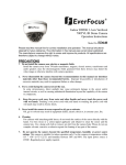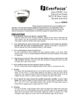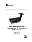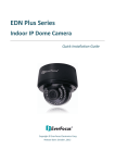
1
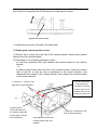
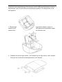
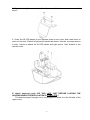
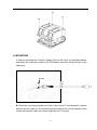
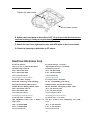
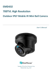
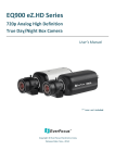
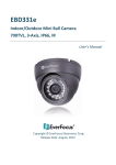
Mobile IR Wedge Cameras Operation Instructions EMW330 Dual Viewing Position EMW330T Varifocal AI Lens Please read this manual first for correct installation and operation. This manual should be retained for future reference. The information in this manual was current when published. The manufacturer reserves the right to revise and improve its products. All specifications are therefore subject to change without notice. PRECAUTIONS 1. Do not install the camera near electric or magnetic fields. 2. Install the camera away from TV/radio transmitters, magnets, electric motors, transformers and audio speakers since the electromagnetic fields generated from these devices may distort the video image. Never disassemble the camera beyond the recommendations in this manual nor introduce 4. materials other than those recommended herein. Improper disassembly or introduction of corrosive materials may result in equipment failure or other damage. Try and avoid facing the camera toward the sun. In some circumstances, direct sunlight may cause permanent damage to the sensor and/or internal circuits. Keep the power cord away from water and other liquids and never touch the power cord with 5. wet hands. Touching a wet power cord with the hands or touching the power cord with wet hands may result in electric shock. Cleaning Use a damp soft cloth to remove any dirt from the camera body, being careful not to scratch 3. 6. the covers over the lens and IR emitters. Use lens tissue or a cotton tipped applicator and ethanol if it becomes necessary to clean the camera lens. Please do not use complex solvents, corrosive or abrasive agents for cleaning. Do not operate the camera beyond the specified temperature, humidity or power source ratings. Use the camera at temperatures within -40ºC ~ 60ºC (-40F~140F) . The input power source is 12VDC. TABLE OF CONTENTS 1. PRODUCT OVERVIEW............................................................................................ 2 2. COMMON FEATURES ............................................................................................. 2 3. CONTENT LIST........................................................................................................ 2 4. SPECIFICATIONS .................................................................................................... 3 5. CONFIGURATION.................................................................................................... 4 6. MOUNTING ............................................................................................................ 10 -1- 1. PRODUCT OVERVIEW With a streamlined, vandal resistant, IP67 weatherproof wedge type chassis, the EMW330 is ideal for transit/school bus and similar applications. Choose the EMW330 fixed lens model with dual-position lens and IR illuminator modules, enabling the user to field select a side, rear, wall or ceiling mounting configuration for best viewing angle, and mount the camera easily without brackets. The IR illuminators provide clear images up to 50 feet away. Or, for flexibility in field of view choose the EMW330T with choice of 2.9~10mm auto-iris varifocal lens, true day/night operation and ability to rotate the viewing angle for side, wall or ceiling mounting. Both cameras have built-in visible light sensors to monitor ambient light and provide IR illumination when needed. 2. COMMON FEATURES 1/3” Sony Super HAD CCD Resolution: 520 TVL Vandal resistant, IP67 housing Dual IR illuminators for 50 foot range Side/Rear/Wall/Ceiling mounting options Built-in heater. Video Test Connector UNIQUE FEATURES EMW330T vari-focal lens model with ICR EMW330 fixed lens model with dual-position lens 3. CONTENT LIST 1. 2. 3. 4. 5. 6. 7. 8. Camera unit User’s manual Accessory kit containing: i. Front light sensor bracket (EMW330 only) ii. 4 screws and plastic anchors iii. 4 sheet metal screws and rubber washers iv. Tool for tamper resistant cover screws Mounting template Desiccant pack with gummed tape to attach pack inside camera Rubber gasket for base of camera Power adapter pigtail Video Test Cable -2- 4. SPECIFICATIONS EMW300 EMW330T Pickup Device 1/3" SONY Super HAD CCD Video Format NTSC and PAL models available Scanning System NTSC: 525TV lines, 60 fields/sec; PAL: 625 TV lines, 50 field/sec Picture Elements 768 x 494(NTSC); 752 X 582 (PAL) Horizontal Resolution 520 TVL Sensitivity 0.4 Lux / F=1.2(IR OFF); 0 Lux (IR ON) S/N Ratio Over 48 dB (AGC off) Electronic Shutter Video Outputs 1/50(1/60) ~ 1/100,000 BNC 1.0Vp-p, 75ohm; video test port Gamma Correction Lens Type 0.45 Fixed focal length f=3.6, 4.3, 6, 8, 12mm (3.6mm standard) Vari-Focal Lens, V3: f=2.9~10mm/F=1.2, Back Light Comp. Yes (ON) Auto Gain control Yes (ON) Auto White Balance Sync. Mode Day/Night Yes (2500۫K~9000۫K) Internal sync Electronic Day/Night Detection Auto; IR Cut Removable Visible light sensor Built-in Heater IR LEDS IR LED Lifespan Yes 40 emitters in two arrays 20,000 hours nominal IR Distance 50 feet IR Wavelength 850nm Weather Proof IP67 Vandal Resistant Yes Power source Power consumption Operating Temperature 12VDC 4.8W max at 12VDC (Heater ON & IR LED ON) -40°C~60°C, -40°F~140°F Dimensions WxDxH 105 x 140 x 65mm Weight 600g Mounting Options Side/Rear/Wall/Ceiling mounting options, no bracket required Camera Angle Can be rotated 360º on axis in 90º increments to fit mounting position Viewing Direction Dual-Position -3- Single-Position IR LEDs Direction (end/side) Certifications (end) CE/FCC 5. CONFIGURATION A. To open the housing/remove the cover 1. Using the tool provided remove 4 screws to separate camera’s base from its cover. 2. Detach the light sensor wire and LED wires from connectors on the camera PCB board. 3. Detach LED illuminator wire from wire retaining clip on camera body. -4- 4. Detach the safety cord from the camera base. B. Making the Z-axis adjustment 1. Remove the two screws closest to the front of the camera bracket and loosen the two screws at the side of the camera bracket. Remove these screws Loosen these screws 2. Make Z-axis adjustment. To avoid distortion, do NOT point the camera at the corner -5- of the lens cover. If the Z-axis is rotated past 45º (side view, EMW330 only), see step D below to reposition the IR illuminators and light sensor bracket. Tighten the side screws. 3. Install the second pair of screws if the holes align. C. Rotating the camera module on-axis 1) Remove the 4 screws from the side of the camera bracket. Remove the module bracket from the camera bracket. 2) Depending on the mounting orientation, either a) Invert the assembly 180º and reattach the module bracket to the camera bracket - or b) Remove two screws from the front of the module bracket, rotate the module right or left 90° so that the lens is positioned to the correct direction, and reassemble the module to the module bracket, then reattach the module bracket to the camera bracket. 1) Remove 2 screws from right side of camera bracket Note two red arrows indicating proper orientation of camera module. When unit is installed, these arrows should be pointing UP. 2b) Remove the module bracket from the module, Adjust the module right or left 90° and reassemble. 1) Remove 2 screws from left side of camera bracket 2a) Rotate the module and module bracket 180° -and 6reattach D. EMW330 ONLY Change the viewing direction. If the Z-axis adjustment above points the lens toward the side of the housing, the IR LEDs and light sensor must be repositioned. Here, the IR LEDs are at factory/end position. To change them to the side position: 1. Remove the detach the IR bracket from 4 screws as shown in figure to LED panels and light sensor upper the camera cover. 2. Replace the factory light sensor “end” bracket by the light sensor “side” bracket: Remove the 2 screws from the light sensor “end” bracket. -7- 3. Reattach the light sensor to the “side” bracket with the same screws removed in step 2. 4. Cross the IR LED panels to the opposite sides of the cover, and rotate them to point out the side. Place the light senor bracket as shown. Use the 4 screws remove in step 1 above to attach the IR LED panels and light sensor “side” bracket to the camera cover. E. Attach desiccant pack (DO THIS LAST JUST BEFORE CLOSING THE HOUSING WHEN THE INSTALLATION IS COMPLETE.) The desiccant pack has glue on it; use the glue to attach it on the left side of the upper cover. -8- F. Reattach cover and seal housing 1. Reversing the steps in A above a. Reattach the safety cord to the base; position the metal ferrule to the side so it does not overlap the gasket and interfere with the cover when it is replaced. b. Reattach the LED illuminator wires and place into clips. c. Reattach the light sensor wire 2. Replace the cover onto the base, making sure the gasket lies flat between the base and cover. -9- 3. Attach the cover with the four screws removed during step A-1. 6. MOUNTING A. Before mounting the Camera, please remove the cover as described above, and attach the video test cable to the PCB board (note that the ground pin is the upper pin). Ground Video B. Place the mounting template and drill 4 pilot holes (3.7mm diameter if plastic anchors are not used) for the mounting screws using a drill, and a clearance hole for the video/power cable connectors (typically 9/16” or more). - 10 - C. Apply sealant generously around all holes. Place the camera and rubber gasket to align the mounting holes with the pilot holes or anchors. Insert the mounting screws, using the rubber washers and tighten fully using the appropriate screwdriver or drive tool. D. Adjust the angle and while viewing the image (using a test monitor such as the EN200.) F. Lock the two screws closest to the front of the camera bracket and tighten the two screws at the side of the camera bracket. - 11 - Tighten the side screws Lock these screws E. Attach desiccant pack as described in 5F. Do not open the desiccant pack until the housing is ready to be permanently sealed. F. Attach the top cover light sensor wire and LED wires to their connectors. G. Close the housing as described in 5F above. EverFocus Electronics Corp. EverFocus Taiwan: EverFocus Europe - Germany: 12F, No.79, Sec. 1, Shin-Tai Wu Road, Albert-Einstein-Strasse 1, D-46446 Hsi-Chih, Taipei, Taiwan Emmerich, Germany TEL: +886 2 2698 2334 TEL: +49 2822 93940 FAX: +886 2 2698 2380 FAX: +49 2822 939495 www.everfocus.com.tw www.everfocus.de [email protected] [email protected] EverFocus China - Beijing: EverFocus China - Shenzhen: Room 609, Technology Trade Building, 4F, No. 2, D4 Building, Wan Yelong Shangdi Information Industry Base, Industrial Park, Tangtou Road, Shiyan, Haidian District, Beijing 100085, China Baoan, Shenzhen, Guangdong 518101, China TEL: +86 10 6297 3336~39 TEL: +86 755 2765 1313 FAX: +86 10 6297 1423 FAX: +86 755 2765 0337 www.everfocus.com.cn www.everfocus.com.cn [email protected] [email protected] EverFocus USA - California: EverFocus USA - New York: 1801 Highland Avenue, Unit A, Duarte, CA 415 Oser Avenue, Unit S, Hauppauge, NY 11788, 91010, USA USA TEL: +1 626 844 8888 TEL: +1 631 436 5070 FAX: +1 626 844 8838 FAX: +1 631 436 5027 www.everfocus.com www.everfocus.com - 12 - [email protected] EverFocus Japan: 5F, Kinshicho City Building, 2-13-4 Koto-Bashi,Sumida-Ku, Tokyo, 130-0022, Japan TEL: +81 3 5625 8188 FAX: +81 3 5625 8189 www.everfocus.co.jp [email protected] EverFocus India: Suite 803, Housefin Bhavan, C-21, Bandra Kurla Complex, Bandra (East), Mumbai 400051, India TEL: +91 22 6128 8700 FAX: +91 22 6128 8705 www.everfocus.in [email protected] Your EverFocus product is designed and manufactured with high quality materials and components which can be recycled and reused. This symbol means that electrical and electronic equipment, at their end-of-life, should be disposed of separately from your household waste. Please, dispose of this equipment at your local community waste collection/recycling centre. In the European Union there are separate collection systems for used electrical and electronic product. Please, help us to conserve the environment we live in! [email protected] EverFocus Europe - UK: Unit 12, Spitfire Business Park, Hawker Road, Croydon Surrey, CR0 4WD, UK TEL: +44 (0) 20 8649 9757 / 0845 430 9999 FAX: +44 (0) 20 8649 9907 www.everfocus.com [email protected] Ihr EverFocus Produkt wurde entwickelt und hergestellt mit qualitativ hochwertigen Materialien und Komponenten, die recycelt und wieder verwendet werden können. Dieses Symbol bedeutet, dass elektrische und elektronische Geräte am Ende ihrer Nutzungsdauer vom Hausmüll getrennt entsorgt werden sollen. Bitte entsorgen Sie dieses Gerät bei Ihrer örtlichen kommunalen Sammelstelle oder im Recycling Centre. Helfen Sie uns bitte, die Umwelt zu erhalten, in der wir leben! - 13 -