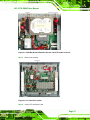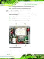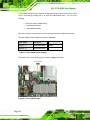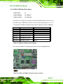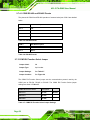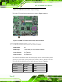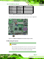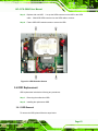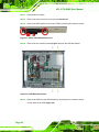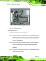
1
AFL-517A-GM45 User Manual IEI Technology Corp. MODEL: AFL-517A-GM45 High Performance Panel PC with Intel® Core™2 Duo CPU Fan less, Touch Screen, 802.11 b/g/n Wireless LAN, Gigabit Ethernet, HDMI, DisplayPort, USB, Audio, RS-232/422/485, SATA, RoHS Compliant, IP 64 Protection User Manual Page i Rev. 2.10 – 12 October, 2011 AFL-517A-GM45 User Manual Revision Date Version Changes 12 October, 2011 2.10 Initial release Page ii AFL-517A-GM45 User Manual Copyright COPYRIGHT NOTICE The information in this document is subject to change without prior notice in order to improve reliability, design and function and does not represent a commitment on the part of the manufacturer. In no event will the manufacturer be liable for direct, indirect, special, incidental, or consequential damages arising out of the use or inability to use the product or documentation, even if advised of the possibility of such damages. This document contains proprietary information protected by copyright. All rights are reserved. No part of this manual may be reproduced by any mechanical, electronic, or other means in any form without prior written permission of the manufacturer. TRADEMARKS All registered trademarks and product names mentioned herein are used for identification purposes only and may be trademarks and/or registered trademarks of their respective owners. Page iii AFL-517A-GM45 User Manual Table of Contents 1 INTRODUCTION........................................................................................................ 14 1.1 OVERVIEW................................................................................................................ 15 1.1.1 Features ........................................................................................................... 16 1.2 EXTERNAL OVERVIEW .............................................................................................. 16 1.2.1 Front Panel ...................................................................................................... 16 1.2.2 Rear Panel ....................................................................................................... 17 1.2.3 I/O Interface Panel .......................................................................................... 18 1.3 INTERNAL OVERVIEW ............................................................................................... 19 1.4 MODEL VARIATIONS ................................................................................................. 19 1.5 SYSTEM SPECIFICATIONS .......................................................................................... 19 1.6 DIMENSIONS ............................................................................................................. 21 2 INSTALLATION ......................................................................................................... 23 2.1 UNPACK THE PANEL PC............................................................................................ 24 2.2 PACKING LIST........................................................................................................... 25 2.3 REMOVING THE REAR PANEL ................................................................................... 28 2.4 CF CARD INSTALLATION .......................................................................................... 30 2.5 HARD DRIVE INSTALLATION ..................................................................................... 32 2.6 AT/ATX MODE SELECTION ...................................................................................... 33 2.6.1 AT Power Mode................................................................................................ 33 2.6.2 ATX Power Mode ............................................................................................. 33 2.7 JUMPER SETTINGS .................................................................................................... 34 2.7.1 Accessing the Jumpers ..................................................................................... 35 2.7.2 Preconfigured Jumpers .................................................................................... 35 2.7.3 Clear CMOS Jumper........................................................................................ 35 2.7.4 COM1, COM3 Port Pin 9 Select...................................................................... 37 2.7.4.1 COM3 RS-422 and RS-485 Pinouts ......................................................... 38 2.7.5 COM3 RX Function Select Jumper.................................................................. 38 2.7.6 COM3 TX Function Select Jumper .................................................................. 39 2.7.7 COM3 RS-232/422/485 Serial Port Select Jumper ......................................... 40 2.8 MOUNTING THE SYSTEM .......................................................................................... 41 Page iv AFL-517A-GM45 User Manual 2.8.1 Wall Surface Mounting..................................................................................... 42 2.8.2 Panel Mounting................................................................................................ 44 2.8.3 Cabinet and Rack Installation ......................................................................... 46 2.8.4 Arm Mounting .................................................................................................. 48 2.9 BOTTOM PANEL CONNECTORS ................................................................................. 50 2.9.1 LAN Connection............................................................................................... 50 2.9.2 Serial Device Connection ................................................................................ 51 2.9.2.1 COM3 RS-232, RS-422 and RS-485 Pinouts ........................................... 52 2.9.3 USB Device Connection................................................................................... 53 2.9.4 VGA connection ............................................................................................... 54 2.10 POWER CONNECTION ............................................................................................. 55 2.11 DRIVER INSTALLATION ........................................................................................... 56 3 SYSTEM MAINTENANCE ....................................................................................... 57 3.1 SYSTEM MAINTENANCE INTRODUCTION .................................................................. 58 3.2 MOTHERBOARD REPLACEMENT ............................................................................... 58 3.3 COVER REMOVAL ..................................................................................................... 58 3.4 MEMORY MODULE REPLACEMENT........................................................................... 60 3.5 HARD DRIVE REPLACEMENT .................................................................................... 62 3.6 ODD REPLACEMENT ................................................................................................ 63 3.6.1 ODD Removal.................................................................................................. 63 3.6.2 ODD Installation ............................................................................................. 65 3.7 REINSTALLING THE COVERS ..................................................................................... 66 4 BIOS OPTIONS ........................................................................................................... 67 4.1 INTRODUCTION......................................................................................................... 68 4.1.1 Starting Setup................................................................................................... 68 4.1.2 Using Setup ...................................................................................................... 68 4.1.3 Getting Help..................................................................................................... 69 4.1.4 Unable to Reboot After Configuration Changes.............................................. 69 4.1.5 BIOS Menu Bar................................................................................................ 69 4.2 MAIN........................................................................................................................ 70 4.3 ADVANCED ............................................................................................................... 71 4.3.1 CPU Configuration.......................................................................................... 72 4.3.2 IDE Configuration ........................................................................................... 73 Page v AFL-517A-GM45 User Manual 4.3.2.1 IDE Master, IDE Slave ............................................................................. 74 4.3.3 Super IO Configuration ................................................................................... 79 4.3.4 Hardware Health Configuration...................................................................... 82 4.3.5 AHCI Configuration......................................................................................... 86 4.3.5.1 AHCI Port n .............................................................................................. 87 4.3.6 Remote Configuration ...................................................................................... 88 4.3.7 USB Configuration........................................................................................... 90 4.3.8 Power Configuration........................................................................................ 92 4.4 PCI/PNP................................................................................................................... 93 4.5 BOOT........................................................................................................................ 95 4.5.1 Boot Settings Configuration............................................................................. 96 4.6 SECURITY ................................................................................................................. 98 4.7 CHIPSET ................................................................................................................... 98 4.7.1 Northbridge Chipset Configuration............................................................... 100 4.7.2 Southbridge Configuration ............................................................................ 101 4.8 EXIT ....................................................................................................................... 103 5 ISMM .......................................................................................................................... 105 5.1 ISMM INTRODUCTION ........................................................................................... 106 5.2 ISMM INSTALLATION ............................................................................................. 106 5.3 VOLTAGE PAGE ....................................................................................................... 108 5.3.1 Refresh Time Setting....................................................................................... 109 5.3.2 High Limit Value and Low Limit Value Setting .............................................. 109 5.4 FAN PAGE ................................................................................................................110 5.4.1 Refresh Time Setting........................................................................................ 111 5.4.2 High Limit Value and Low Limit Value Setting ............................................... 111 5.4.3 Smart Fan Setting ...........................................................................................112 5.4.3.1 On/Off Mode............................................................................................112 5.4.3.2 PWM Mode..............................................................................................112 5.4.3.3 Automatic Mode.......................................................................................113 5.5 TEMPERATURE PAGE ...............................................................................................114 5.5.1 Refresh Time Setting........................................................................................115 5.5.2 High Limit Value and Low Limit Value Setting ...............................................116 5.6 CASH DRAWER PAGE ...............................................................................................117 5.7 WATCHDOG TIMER PAGE .........................................................................................118 Page vi AFL-517A-GM45 User Manual 5.8 DIO PAGE ...............................................................................................................119 5.8.1 GPO Information Setting ................................................................................119 5.9 LOAD/SAVE PAGE ................................................................................................... 120 A SAFETY PRECAUTIONS ....................................................................................... 121 A.1 SAFETY PRECAUTIONS .......................................................................................... 122 A.1.1 General Safety Precautions ........................................................................... 122 A.1.2 Anti-static Precautions .................................................................................. 123 A.2 MAINTENANCE AND CLEANING PRECAUTIONS ...................................................... 123 A.2.1 Maintenance and Cleaning............................................................................ 123 A.2.2 Cleaning Tools ............................................................................................... 124 B BIOS OPTIONS ........................................................................................................ 125 C ONE KEY RECOVERY........................................................................................... 128 C.1 ONE KEY RECOVERY INTRODUCTION .................................................................... 129 C.1.1 System Requirement ...................................................................................... 130 C.1.2 Supported Operating System......................................................................... 131 C.2 SETUP PROCEDURE FOR WINDOWS ........................................................................ 132 C.2.1 Hardware and BIOS Setup ............................................................................ 132 C.2.2 Create Partitions ........................................................................................... 133 C.2.3 Install Operating System, Drivers and Applications..................................... 136 C.2.4 Build-up Recovery Partition.......................................................................... 137 C.2.5 Create Factory Default Image ...................................................................... 139 C.3 SETUP PROCEDURE FOR LINUX .............................................................................. 144 C.4 RECOVERY TOOL FUNCTIONS ................................................................................ 147 C.4.1 Factory Restore ............................................................................................. 149 C.4.2 Backup System............................................................................................... 150 C.4.3 Restore Your Last Backup.............................................................................. 151 C.4.4 Manual .......................................................................................................... 152 C.5 OTHER INFORMATION ............................................................................................ 153 C.5.1 Using AHCI Mode or ALi M5283 / VIA VT6421A Controller ...................... 153 C.5.2 System Memory Requirement ........................................................................ 155 D TERMINOLOGY ..................................................................................................... 156 E WATCHDOG TIMER............................................................................................... 160 Page vii AFL-517A-GM45 User Manual F HAZARDOUS MATERIALS DISCLOSURE........................................................ 163 F.1 HAZARDOUS MATERIALS DISCLOSURE TABLE FOR IPB PRODUCTS CERTIFIED AS ROHS COMPLIANT UNDER 2002/95/EC WITHOUT MERCURY ..................................... 164 Page viii AFL-517A-GM45 User Manual List of Figures Figure 1-1: AFL-517A-GM45 Flat Panel PC ................................................................................15 Figure 1-2: AFL-517A-GM45 Front View .....................................................................................17 Figure 1-3: AFL-517A-GM45 Rear View ......................................................................................18 Figure 1-4: AFL-517A-GM45 I/O Interface Connector Panel.....................................................19 Figure 1-5: AFL-517A-GM45 Dimensions (mm) .........................................................................22 Figure 2-1: Back Cover Retention Screws .................................................................................29 Figure 2-2: Aluminum Cover Retention Screws ........................................................................29 Figure 2-3: HDD Bay Bracket Retention Screws and SATA Cable Locations........................31 Figure 2-4: CF Card Slot Location ..............................................................................................31 Figure 2-5: HDD Retention Screws .............................................................................................32 Figure 2-6: AT/ATX Switch Location...........................................................................................33 Figure 2-7: Clear CMOS Jumper .................................................................................................36 Figure 2-8: COM1 and COM3 Pin 9 Setting Jumper Locations................................................37 Figure 2-9: COM3 RX Function Select Jumper Location..........................................................39 Figure 2-10: COM3 TX Function Select Jumper Pinout Locations..........................................40 Figure 2-11: COM3 RS-232/422/485 Serial Port Select Jumper Location................................41 Figure 2-12: Wall-mounting Bracket ...........................................................................................42 Figure 2-13: Chassis Support Screws ........................................................................................43 Figure 2-14: Secure the Panel PC ...............................................................................................44 Figure 2-15: AFL-517A-GM45 Cutout Dimensions (units in mm) ............................................45 Figure 2-16: Tighten the Panel Mounting Clamp Screws .........................................................46 Figure 2-17: The Rack/Cabinet Bracket......................................................................................47 Figure 2-18: Secure the Rack/Cabinet Bracket..........................................................................47 Figure 2-19: Install into a Rack/Cabinet .....................................................................................48 Figure 2-20: AFL-412A-N270 Arm Mounting Retention Screw Holes......................................49 Figure 2-21: AFL-517A-GM45 I/O Interface Connector Panel...................................................50 Figure 2-22: LAN Connection ......................................................................................................51 Figure 2-23: Serial Device Connector.........................................................................................52 Figure 2-24: USB Device Connection .........................................................................................54 Figure 2-25: VGA Connector .......................................................................................................55 Page ix AFL-517A-GM45 User Manual Figure 3-1: Back Cover Retention Screws .................................................................................59 Figure 3-2: Aluminum Cover Retention Screws ........................................................................60 Figure 3-3: POC-GM45 SERIES ODD Bay Bracket Removal ....................................................61 Figure 3-4: POC-GM45 SERIES SO-DIMM Socket Location .....................................................61 Figure 3-5: DDR2 SO-DIMM Module Installation........................................................................62 Figure 3-6: HDD Retention Screws .............................................................................................63 Figure 3-7: SATA Cable Retention Screws ................................................................................64 Figure 3-8: ODD Retention Screws .............................................................................................64 Figure 3-9: ODD Retention Screws .............................................................................................65 Figure 5-1: iSMM Installation Welcome Screen...................................................................... 106 Figure 5-2: iSMM Installation Customer Information ............................................................. 107 Figure 5-3: Ready to Install the Program Window ................................................................. 107 Figure 5-4: Voltage Page........................................................................................................... 108 Figure 5-5: Voltage Refresh Time Setting ............................................................................... 109 Figure 5-6: Voltage Page – High Limit and Low Limit............................................................ 109 Figure 5-7: Fan Page ................................................................................................................. 110 Figure 5-8: Fan Speed Refresh Time Setting.......................................................................... 111 Figure 5-9: Fan Page – High Limit and Low Limit .................................................................. 111 Figure 5-10: Smart Fan Setting – On/Off Mode....................................................................... 112 Figure 5-11: Smart Fan Setting – PWM Mode ......................................................................... 113 Figure 5-12: Smart Fan Setting – Automatic Mode ................................................................ 114 Figure 5-13: Temperature Page................................................................................................ 115 Figure 5-14: Temperature Refresh Time Setting .................................................................... 115 Figure 5-15: Temperature Page – High Limit and Low Limit................................................. 116 Figure 5-16: Cash Drawer Page................................................................................................ 117 Figure 5-17: WDT Page ............................................................................................................. 118 Figure 5-18: DIO Page ............................................................................................................... 119 Figure 5-19: Load/Save Page.................................................................................................... 120 Figure C-1: IEI One Key Recovery Tool Menu ........................................................................ 129 Figure C-2: Launching the Recovery Tool .............................................................................. 133 Figure C-3: Recovery Tool Setup Menu .................................................................................. 134 Figure C-4: Command Mode..................................................................................................... 134 Figure C-5: Partition Creation Commands.............................................................................. 135 Figure C-6: Launching the Recovery Tool .............................................................................. 137 Figure C-7: System Configuration for Windows .................................................................... 137 Page x AFL-517A-GM45 User Manual Figure C-8: Build-up Recovery Partition ................................................................................. 138 Figure C-9: Press any key to continue .................................................................................... 138 Figure C-10: Press F3 to Boot into Recovery Mode............................................................... 139 Figure C-11: Recovery Tool Menu ........................................................................................... 139 Figure C-12: About Symantec Ghost Window ........................................................................ 140 Figure C-13: Symantec Ghost Path ......................................................................................... 140 Figure C-14: Select a Local Source Drive ............................................................................... 141 Figure C-15: Select a Source Partition from Basic Drive ...................................................... 141 Figure C-16: File Name to Copy Image to ............................................................................... 142 Figure C-17: Compress Image.................................................................................................. 142 Figure C-18: Image Creation Confirmation ............................................................................. 143 Figure C-19: Image Creation Process...................................................................................... 143 Figure C-20: Image Creation Complete ................................................................................... 143 Figure C-21: Press Any Key to Continue ................................................................................ 144 Figure C-22: Partitions for Linux.............................................................................................. 145 Figure C-23: System Configuration for Linux......................................................................... 146 Figure C-24: Access menu.lst in Linux (Text Mode) .............................................................. 146 Figure C-25: Recovery Tool Menu ........................................................................................... 147 Figure C-26: Recovery Tool Main Menu .................................................................................. 148 Figure C-27: Restore Factory Default ...................................................................................... 149 Figure C-28: Recovery Complete Window .............................................................................. 149 Figure C-29: Backup System.................................................................................................... 150 Figure C-30: System Backup Complete Window ................................................................... 150 Figure C-31: Restore Backup ................................................................................................... 151 Figure C-32: Restore System Backup Complete Window ..................................................... 151 Figure C-33: Symantec Ghost Window ................................................................................... 152 Page xi AFL-517A-GM45 User Manual List of Tables Table 1-1: AFL-517A-GM45 Specifications ................................................................................19 Table 1-2: AFL-517A-GM45 Specifications ................................................................................21 Table 2-1: Jumpers .......................................................................................................................34 Table 2-2: Preconfigured Jumpers .............................................................................................35 Table 2-3: Clear CMOS Jumper Settings....................................................................................36 Table 2-4: COM1 Pin 9 Setting Jumper Settings .......................................................................37 Table 2-5: RS-422 Pinouts ...........................................................................................................38 Table 2-6: RS-485 Pinouts ...........................................................................................................38 Table 2-7: COM3 RX Function Select Jumper Settings ............................................................38 Table 2-8: COM3 TX Function Select Jumper Settings.............................................................40 Table 2-9: COM3 RS-232/422/485 Serial Port Select Jumper Settings ....................................41 Table 2-10: RS-232 Pinouts .........................................................................................................52 Table 2-11: RS-422 Pinouts .........................................................................................................53 Table 2-12: RS-485 Pinouts .........................................................................................................53 Table 4-1: BIOS Navigation Keys ................................................................................................69 Page xii AFL-517A-GM45 User Manual BIOS Menus BIOS Menu 1: Main .......................................................................................................................70 BIOS Menu 2: Advanced ..............................................................................................................72 BIOS Menu 3: CPU Configuration ...............................................................................................72 BIOS Menu 4: IDE Configuration.................................................................................................73 BIOS Menu 5: IDE Master and IDE Slave Configuration ...........................................................75 BIOS Menu 6: Super IO Configuration........................................................................................79 BIOS Menu 7: Hardware Health Configuration ..........................................................................82 BIOS Menu 8: AHCI Configuration..............................................................................................86 BIOS Menu 9: AHCI Port n Configuration Menu........................................................................87 BIOS Menu 10: Remote Access Configuration..........................................................................88 BIOS Menu 11: USB Configuration .............................................................................................90 BIOS Menu 12: ACPI Configuration ............................................................................................92 BIOS Menu 13: PCI/PnP Configuration.......................................................................................93 BIOS Menu 14: Boot .....................................................................................................................95 BIOS Menu 15: Boot Settings Configuration .............................................................................96 BIOS Menu 16: Security ...............................................................................................................98 BIOS Menu 17: Chipset ................................................................................................................99 BIOS Menu 18:Northbridge Chipset Configuration................................................................ 100 BIOS Menu 19: Southbridge Chipset Configuration .............................................................. 102 BIOS Menu 20:Exit..................................................................................................................... 103 Page xiii AFL-517A-GM45 User Manual Chapter 1 1 Introduction Page 14 AFL-517A-GM45 User Manual 1.1 Overview Figure 1-1: AFL-517A-GM45 Flat Panel PC The AFOLUX AFL-517A-GM45 is an Intel® Core™2 Duo T9400/T7500 or Intel® Celeron® M 575 powered all-in-one touch screen panel PCs with a rich variety of functions and peripherals connections. It is designed for easy and simplified integration into conference center, home automation, and building control applications. An Intel® GM45 graphics memory controller hub (GMCH) coupled with an Intel® ICH9M input/output controller hub ensures optimal memory, graphics, and peripheral I/O support. The system comes with 1.0 GB or 2.0 GB of preinstalled DDR2 SDRAM and supports a maximum of 4.0 GB of DDR2 SDRAM ensuring smooth data throughputs with reduced bottlenecks and fast system access. The AFL-GM45 Series is also preinstalled with a DVD Combo drive and includes a bay for a 2.5” SATA2 HDD for data storage. Two serial ports and four external USB 2.0 ports ensure simplified connectivity to a variety of external peripheral devices. Wireless LAN and dual RJ-45 Ethernet connectors ensure uninterrupted connection to an external LAN. The AFL-517A-GM45 includes both audio and visual multimedia capabilities. All models have VGA, HDMI, and DisplayPort outputs for connecting another monitor to the system. Page 15 AFL-517A-GM45 User Manual A rich high definition audio experience is supported through the HDMI, DisplayPort, and audio jack connections. The AFL-517A-GM45 panel PC is an elegant yet sophisticated system that is as easily implemented in commercial, industrial, and corporate environments as the home. 1.1.1 Features The AFL-517A-GM45 features the following: Intel® Core™2 Duo T9400/7500 or Intel® Celeron® M 575 processor Intel® GM45 + ICH9M chipset 1GB or 2GB DDR2 SDRAM preinstalled 802.11 b/g wireless module Four USB 2.0 ports Watchdog timer that triggers a system reset if the system hangs for some reason IP 64 compliant front panel Touch screen Bluetooth RoHS compliance 1.2 External Overview The stylish AFL-517A-GM45 panel PC comprises of a screen, rear panel, top panel, bottom panel and two side panels (left and right). An ABS/PC plastic front frame surrounds the front screen. The rear panel provides screw holes for a wall-mounting bracket compliant with the VESA FDMI standard. An I/O interface panel on the bottom panel provides access to external interface connectors. 1.2.1 Front Panel The front side of the AFL-517A-GM45 is a flat panel TFT LCD screen surrounded by an ABS/PC plastic frame. The top center has a power LED. The bottom includes a guide to the OSD keypad controls. Refer to Figure 1-2. Page 16 AFL-517A-GM45 User Manual Figure 1-2: AFL-517A-GM45 Front View 1.2.2 Rear Panel The rear panel provides access to the internal components of the POC-GM45 SERIES. Refer to Figure 1-3 for back cover retention screw and VESA mount screw holes. Page 17 AFL-517A-GM45 User Manual Figure 1-3: AFL-517A-GM45 Rear View 1.2.3 I/O Interface Panel The I/O interface panel located on the bottom of the AFL-517A-GM45 has the following I/O interface connectors: 1 x 12 V DC-IN connector 1 x Audio line-in connector 2 x LAN connectors 1 x Power switch 1 x Reset button 1 x RS-232 serial port 1 x RS-232/422/485 serial port 1 x HDMI output port 1 x Display Port 1 x VGA port 4 x USB 2.0 ports The external I/O interface connector panel is shown in below. Page 18 AFL-517A-GM45 User Manual Figure 1-4: AFL-517A-GM45 I/O Interface Connector Panel 1.3 Internal Overview All the components are contained under the rear panel. The internal components include the touch panel module and the motherboard. The motherboard has memory and a wireless LAN module. An HSDPA module is available preinstalled or as an optional add-on. The AFL-517A-GM45 includes a DVD Combo drive and bay for a 2.5” SATA HDD. 1.4 Model Variations The AFL-517A-GM45 is available in the following model variations. Model No. CPU Memory AFL-517A-GM45-T94/R/D/2G-R21 Intel® Core™2 Duo T9400 2.53 GHz 2GB DDR2 AFL-517A-GM45-P84/R/D/2G-R21 Intel® Core™2 Duo P8400 2.53 GHz 2GB DDR2 AFL-517A-GM45-CM5/R/D/1G-R21 Intel® Celeron® M 575 2.0 GHz 1GB DDR2 Table 1-1: AFL-517A-GM45 Specifications 1.5 System Specifications The technical specifications for the AFL-517A-GM45 systems are listed below. Specifications AFL-517A-GM45 LCD Size 17" Max Resolution 1280 x 1024 Page 19 AFL-517A-GM45 User Manual Specifications AFL-517A-GM45 Brightness (cd/m2) 300 Contrast Ratio 800:1 LCD Color 16.7M Pixel Pitch (mm) 0.264(H) x 0.264(V) Viewing Angle (H-V) 160/160 Backlight MTBF 40000 hrs SBC Model AFLMB5-GM45-R10 Intel® Core™2 Duo T9400 2.53 GHz CPU options Intel® Core™2 Duo P8400 2.6 GHz Intel® Celeron® M 575 2.0 GHz Chipset Intel® GM45 + ICH9M 1 or 2 GB preinstalled (see model variations) RAM Two 200-pin 667 or 800 MHz DDR2 SO-DIMM (4 GB Max.) supported One Audio line-out jack One DisplayPort One HDMI port One Power jack I/O Ports and Switches One Power switch One Reset button Two RJ-45 GbE LAN ports One RS-232 serial port One RS-232/422/485 serial port Four USB 2.0 ports SSD CF Type II HDD One 2.5” SATA HDD bay ODD SATA slim type DVD Combo drive Watchdog Timer Software programmable supports 1~255 sec. System reset Audio AMP 3W + 3W internal speakers Bluetooth Bluetooth V2.0 module via internal USB interface Wireless LAN Wireless LAN 802.11 b/g/n PCIe mini card module HSDPA Mobile Solution Optional via internal USB interface Page 20 AFL-517A-GM45 User Manual Specifications AFL-517A-GM45 Construction Material ABS + PC Plastic front frame Membrane Keypad (OSD) LCD On/Off, Brightness Up/Down, Volume Up/Down LED Function One Power ON/OFF LED on Front Panel Mounting Panel, Wall, Rack, Arm (VESA 100mm x 100mm) Front Panel Color Silver Dimension (W x H x D mm) 428 x 350 x 79 Operation Temperature (ºC) 0ºC~40ºC with HDD 0ºC~45ºC with CF card or SATA 2.5” SSD HDD Storage Temperature (ºC) -20ºC~60ºC Net Weight 7.5 Kg IP Level Front Frame IP64 EMC CE, FCC, CCC Safety CB Touch Screen Resistive 5-Wire 150W Power Adapter Power Adapter 90VAC~264VAC, 50/60Hz, 12VDC Power Requirement 12VDC Power Consumption 92W Table 1-2: AFL-517A-GM45 Specifications 1.6 Dimensions The AFL-408A/B-N270 dimensions are listed and shown in the figure below. Width: 428 mm Height: 350 mm Depth: 79 mm Page 21 AFL-517A-GM45 User Manual Figure 1-5: AFL-517A-GM45 Dimensions (mm) Page 22 AFL-517A-GM45 User Manual Chapter 2 2 Installation Page 23 AFL-517A-GM45 User Manual WARNING: When installing the AFL-517A-GM45, make sure to: Turn the power off: Chance of electrocution. Turn off the monitor and unplug it from the power supply. Only let certified engineers change the hardware settings: Incorrect settings can cause irreparable damage to the product. Install the monitor with assistance: The product is very heavy and may be damaged by drops and bumps. Two or more people should install the panel PC. Take anti-static precautions: Electrostatic discharge can destroy electrical components and injure the user. Users must ground themselves using an anti-static wristband or similar device. The installation steps below should be followed in order. Step 1: Unpack the flat panel PC Step 2: Check all the required parts are included Step 3: Install the hard drive Step 4: Install the CompactFlash® card Step 5: Mount the flat panel PC Step 6: Connect peripheral devices to the bottom panel of the flat panel PC Step 7: Connect the power cable Step 8: Configure the system Step0: 2.1 Unpack the Panel PC To unpack the flat panel PC, follow the steps below: Page 24 AFL-517A-GM45 User Manual WARNING! Only remove the protective plastic cover stuck to the front screen after installation. The plastic layer protects the monitor surface during installation process. Step 1: Carefully cut the tape sealing the box. Only cut deep enough to break the tape. Step 2: Open the outside box. Step 3: Carefully cut the tape sealing the box. Only cut deep enough to break the tape. Step 4: Open the inside box. Step 5: Lift the monitor out of the boxes. Step 6: Remove the peripheral parts box from the main box. 2.2 Packing List The AFL-517A-GM45 flat panel PC is shipped with the following components: Quantity Item 1 Image AFL-517A-GM45 Panel PC P/N: AFL-517A-GM45-T94/R/D/2G-R21 AFL-517A-GM45-P84/R/D/2G-R21 AFL-517A-GM45-CM5/R/D/1G-R21 1 Power adapter P/N: 63000-FSP150AHAN1808-RS Page 25 AFL-517A-GM45 User Manual 1 Power cord P/N: 32000-000002-RS 1 Screw kit (4 x M3; 5mm) P/N: 44233-030081-RS 1 User manual CD and driver CD P/N: 7B000-000087-RS 1 One Key Recovery 1 Touch pen P/N: 43125-0002C0-RS Optional WIN CE 5.0 ALF-517A-GM45-CE-R21 WIN CE 6.0 ALF-517A-GM45-CE060-R21 WIN XPE ALF-517A-GM45-XPE-R21 Linux ALF-517A-GM45-LNX-R21 Panel mounting kit (P/N: AFL-17D) Page 26 AFL-517A-GM45 User Manual Wall mounting kit (P/N: AFLWK-19) Stand (P/N:STAND-A19) Stand (P/N:STAND-B19) X Stand (P/N:STAND-210-RS) Arm (P/N: ARM-11-RS) Arm (P/N: ARM-31-RS) Page 27 AFL-517A-GM45 User Manual Hybrid card reader (P/N: AFLP-17AMSI-U) Magnetic stripe reader (P/N: AFLP-17AMSR-U) DC 12 V Input UPS (P/N: AUPS-B10-R10) DC 9-36V Input UPS (P/N: AUPS-B20-R10) Make sure all the components listed in the packing list are present. If any of these items are missing or damaged, contact the distributor or sales representative immediately. 2.3 Removing the Rear Panel To access the AFL-517A-GM45 internally the rear panel must be removed. To remove the rear panel, please follow the steps below. Step 1: Remove the retention screws (Figure 2-1). Page 28 AFL-517A-GM45 User Manual Figure 2-1: Back Cover Retention Screws Step 2: Lift the off cover after removing the retention screws. More strength maybe required to separate the cover from the chassis. Step 3: Remove the retention screws (Figure 2-2) from the aluminum cover. Figure 2-2: Aluminum Cover Retention Screws Page 29 AFL-517A-GM45 User Manual Step 4: Lift the off cover. WARNING: Failing to reinstall the covers may result in permanent damage to the system. Please make sure all coverings are properly installed. WARNING: Over-tightening rear cover screws will crack the plastic frame. Maximum torque for cover screws is 5 kg-cm (0.36 lb-ft/0.49 Nm). 2.4 CF Card Installation The AFL-517A-GM45 has one CF Type II slot inside the rear panel. The back cover and aluminum inner cover must be removed to access the slot. To install the CF card, follow the instructions below. Step 1: Locate the SATA cable. Remove the retention screws. Disconnect the SATA cable from the HDD if installed. Step 2: Locate the SATA HDD bay bracket. Remove the retention screws. (Figure 2-3). Page 30 AFL-517A-GM45 User Manual Figure 2-3: HDD Bay Bracket Retention Screws and SATA Cable Locations Step 3: Remove the bracket. Figure 2-4: CF Card Slot Location Step 4: Insert a CF card into the slot. Page 31 AFL-517A-GM45 User Manual Step 5: Replace the SATA HDD bay bracket. Reinsert the retention screws. Step 6: Reconnect the SATA cable. Reinsert the retention screws.Step 0: 2.5 Hard Drive Installation The AFL-517A-GM45 has one hard drive bay inside the rear panel. To install a hard drive follow the instructions below. Step 1: Locate the HDD bracket and insert the HDD into the bracket Step 2: Slide HDD SATA connector into the SATA cable to connect. Step 3: Fasten SATA HDD retention screws to secure the HDD. Figure 2-5: HDD Retention Screws Page 32 AFL-517A-GM45 User Manual 2.6 AT/ATX Mode Selection AT and ATX power modes can both be used on the AFL-517A-GM45. The selection is made through an AT/ATX switch on the bottom panel (Figure 2-6). To select AT mode or ATX mode, follow the steps below. Step 4: Locate the AT/ATX switch on the bottom panel (Figure 2-6). Figure 2-6: AT/ATX Switch Location Step 5: Adjust the AT/ATX switch. Step 0: 2.6.1 AT Power Mode With the AT mode selected, the power is controlled by a central power unit rather than a power switch. The AFL-517A-GM45 panel PC turns on automatically when the power is connected. The AT mode benefits a production line to control multiple panel PCs from a central management center and other applications including: ATM Self-service kiosk Plant environment monitoring system Factory automation platform Manufacturing shop flow 2.6.2 ATX Power Mode With the ATX mode selected, the AFL-517A-GM45 panel PC goes in a standby mode when it is turned off. The panel PC can be easily turned on via network or a power switch in standby mode. Remote power control is perfect for advertising applications since the Page 33 AFL-517A-GM45 User Manual broadcasting time for each panel PC can be set individually and controlled remotely. Other possible application includes Security surveillance Point-of-Sale (POS) Advertising terminal 2.7 Jumper Settings NOTE: A jumper is a metal bridge used to close an electrical circuit. It consists of two or three metal pins and a small metal clip (often protected by a plastic cover) that slides over the pins to connect them. To CLOSE/SHORT a jumper means connecting the pins of the jumper with the plastic clip and to OPEN a jumper means removing the plastic clip from a jumper. The following jumpers can be found on the motherboard installed in the AFL-517A-GM45. Before the AFL-517A-GM45 is installed, the jumpers must be set in accordance with the desired configuration. The jumpers on the AFL-517A-GM45 motherboard are listed in Table 2-1. Description Label Type Clear CMOS CLR_CMOS1 2-pin header COM1,COM3 Pin 9 setting J6 10-pin header COM3 RX RS-232/422/485 select J9 6-pin header COM3 TX RS-422/485 select J10 6-pin header COM3 RS-232/422/485 select J5 12-pin header Table 2-1: Jumpers Page 34 AFL-517A-GM45 User Manual 2.7.1 Accessing the Jumpers To access the jumpers, remove the back panel. To remove the back panel, please refer to Section 2.2. 2.7.2 Preconfigured Jumpers WARNING: Do not change the settings on the jumpers in described here. Doing so may disable or damage the system. The following jumpers are preconfigured for the AFL-517A-GM45. Users should not change these jumpers (Table 2-2). Jumper Name Label Type LVDS voltage selection J1 3-pin header Touch Screen Select J12 4-pin header Panel Type and Resolution JP1 8-pin header Table 2-2: Preconfigured Jumpers 2.7.3 Clear CMOS Jumper Jumper Label: CLR_CMOS1 Jumper Type: 2-pin header Jumper Settings: See Table 2-3 Jumper Location: See Figure 2-7 If the AFL-517A-GM45 fails to boot due to improper BIOS settings, the clear CMOS jumper clears the CMOS data and resets the system BIOS information. To do this, use the jumper cap to close the pins for a few seconds then remove the jumper clip. Page 35 AFL-517A-GM45 User Manual If the “CMOS Settings Wrong” message is displayed during the boot up process, the fault may be corrected by pressing the F1 to enter the CMOS Setup menu. Do one of the following: Enter the correct CMOS setting Load Optimal Defaults Load Failsafe Defaults. After having done one of the above, save the changes and exit the CMOS Setup menu. The clear CMOS jumper settings are shown in Table 2-3. Clear CMOS Description Short 1 - 2 Keep CMOS Setup Short 2 - 3 Clear CMOS Setup Default Table 2-3: Clear CMOS Jumper Settings The location of the clear CMOS jumper is shown in Figure 2-7 below. Figure 2-7: Clear CMOS Jumper Page 36 AFL-517A-GM45 User Manual 2.7.4 COM1, COM3 Port Pin 9 Select Jumper Label: J6 Jumper Settings: See Table 2-4 Jumper Location: See Figure 2-8 Use jumper J6 to configure pin 9 settings on COM1 and COM3 DB-9 connectors. Pin 9 on the COM1 and the COM3 DB-9 connectors can be set as the ring (RI) signal, +5 V or +12 V. The COM1 and COM3 Pin 9 Setting jumper selection options are shown in Table 2-4. JP8 Description Short 1-3 COM1 RI Pin use +12 V Short 3-5 COM1 RI Pin use +5 V Short 7-9 COM1 RI Pin use RI Short 2-4 COM3 RI Pin use +12 V Short 4-6 COM3 RI Pin use +5 V Short 8-10 COM3 RI Pin use RI Default Default Table 2-4: COM1 Pin 9 Setting Jumper Settings The COM1 and COM3 Pin 9 Setting jumper location is shown in Figure 2-8 below. Figure 2-8: COM1 and COM3 Pin 9 Setting Jumper Locations Page 37 AFL-517A-GM45 User Manual 2.7.4.1 COM3 RS-422 and RS-485 Pinouts The pinouts for RS-422 and RS-485 operation of external serial port COM 3 are detailed below. COM 3 RS-422 Description Pin 1 TX- Pin 2 TX+ Pin 6 RX- Pin 7 RX+ Table 2-5: RS-422 Pinouts COM 3 RS-485 Description Pin 1 Data- Pin 2 Data+ Table 2-6: RS-485 Pinouts 2.7.5 COM3 RX Function Select Jumper Jumper Label: J9 Jumper Type: 6-pin header Jumper Settings: See Table 2-7 Jumper Location: See Figure 2-9 The COM3 RX Function Select jumper sets the communication protocol used by the COM3 port as RS-232, RS-422 or RS-485. The COM3 RX Function Select jumper settings are shown in Table 2-7. COM3 RX Function Select Description Short 1-2 RS-232 Short 3-4 RS-422 Short 5-6 RS-485 Default Table 2-7: COM3 RX Function Select Jumper Settings Page 38 AFL-517A-GM45 User Manual The COM3 RX Function Select jumper location is shown in Figure 2-9. Figure 2-9: COM3 RX Function Select Jumper Location 2.7.6 COM3 TX Function Select Jumper Jumper Label: J10 Jumper Type: 6-pin header Jumper Settings: See Table 2-8 Jumper Location: See Figure 2-10 The COM3 TX Function Select jumper configures the TX pin on COM3 serial port connector as RS-422 as an RS-485. The COM3 TX Function Select jumper selection options are shown in Table 2-8. COM3 TX Function Select Description Short 1 – 3 RS-422 Default Short 2 – 4 RS-422 Default Short 3 – 5 RS-485 Short 4 – 6 RS-485 Page 39 AFL-517A-GM45 User Manual Table 2-8: COM3 TX Function Select Jumper Settings The COM3 TX Function Select jumper location is shown in Figure 2-10 below. Figure 2-10: COM3 TX Function Select Jumper Pinout Locations 2.7.7 COM3 RS-232/422/485 Serial Port Select Jumper Jumper Label: J5 Jumper Type: 12-pin header (four 3-pin headers combined) Jumper Settings: See Table 2-9 Jumper Location: See Figure 2-11 The COM3 RS-232/422/485 Serial Port Select jumper sets the communication protocol used by the second serial communications port (COM3) as RS-232, RS-422 or RS-485. The COM3 RS-232/422/485 Serial Port Select settings are shown in Table 2-9. RS-232/485 Select Description Short 1-2 RS-232 Default Short 4-5 RS-232 Default Short 7-8 RS-232 Default Page 40 AFL-517A-GM45 User Manual Short 10-11 RS-232 Short 2-3 RS-422/485 Short 5-6 RS-422/485 Short 8-9 RS-422/485 Short 11-12 RS-422/485 Default Table 2-9: COM3 RS-232/422/485 Serial Port Select Jumper Settings The COM3 RS-232/422/485 Serial Port Select jumper location is shown in Figure 2-11. Figure 2-11: COM3 RS-232/422/485 Serial Port Select Jumper Location 2.8 Mounting the System WARNING! When mounting the flat panel PC onto an arm, onto the wall or onto a panel, it is better to have more than one person to help with the installation to make sure the panel PC does not fall down and get damaged. Page 41 AFL-517A-GM45 User Manual The four methods of mounting the AFL-517A-GM45 are listed below. Wall mounting Panel mounting Arm mounting Rack mounting The four mounting methods are described below. 2.8.1 Wall Surface Mounting To mount the flat panel PC onto the wall, please follow the steps below. Step 1: Select the location on the wall for the wall-mounting bracket. Step 2: Carefully mark the locations of the four screw holes in the bracket on the wall. Step 3: Drill four pilot holes at the marked locations on the wall for the bracket retention screws. Step 4: Align the wall-mounting bracket screw holes with the pilot holes. Step 5: Secure the mounting-bracket to the wall by inserting the retention screws into the four pilot holes and tightening them (Figure 2-12). Figure 2-12: Wall-mounting Bracket Page 42 AFL-517A-GM45 User Manual Step 6: Insert the four monitor mounting screws provided in the wall mounting kit into the four screw holes on the real panel of the flat panel PC and tighten until the screw shank is secured against the rear panel (Figure 2-13). Step 7: Align the mounting screws on the monitor rear panel with the mounting holes on the bracket. Step 8: Carefully insert the screws through the holes and gently pull the monitor downwards until the monitor rests securely in the slotted holes (Figure 2-13). Ensure that all four of the mounting screws fit snuggly into their respective slotted holes. NOTE: In the diagram below the bracket is already installed on the wall. Figure 2-13: Chassis Support Screws Step 9: Secure the panel PC by fastening the retention screw of the wall-mounting bracket. (Figure 2-14). Step 0: Page 43 AFL-517A-GM45 User Manual Figure 2-14: Secure the Panel PC 2.8.2 Panel Mounting To mount the AFL-517A-GM45 flat panel PC into a panel, please follow the steps below. Step 1: Select the position on the panel to mount the flat panel PC. Step 2: Cut out a section from the panel that corresponds to the rear panel dimensions of the flat panel PC. Take care that the panel section that is cut out is smaller than the overall size of the metal frame that surrounds the flat panel PC but just large enough for the rear panel of the flat panel PC to fit through (Figure 2-15). Page 44 AFL-517A-GM45 User Manual Figure 2-15: AFL-517A-GM45 Cutout Dimensions (units in mm) Step 3: Slide the flat panel PC through the hole until the aluminum frame is flush against the panel. Step 4: Insert the panel mounting clamps into the pre-formed holes along the edges of the chassis, behind the aluminum frame. Step 5: Tighten the screws that pass through the panel mounting clamps until the plastic caps at the front of all the screws are firmly secured to the panel (Figure 2-16). Step0: Page 45 AFL-517A-GM45 User Manual Figure 2-16: Tighten the Panel Mounting Clamp Screws 2.8.3 Cabinet and Rack Installation The AFL-517A-GM45 flat panel PC can be installed into a cabinet or rack. The installation procedures are similar to the panel mounting installation. To do this, please follow the steps below: NOTE: When purchasing the cabinet/rack installation bracket, make sure it is compatible with both the AFL-517A-GM45 flat panel PC and the rack/cabinet into which the AFL-517A-GM45 is installed. Step 1: Slide the rear of the AFL-517A-GM45 flat panel PC through the rack/cabinet bracket until the aluminum frame is flush against the front of the bracket (Figure 2-17). Page 46 AFL-517A-GM45 User Manual Figure 2-17: The Rack/Cabinet Bracket Step 2: Insert the rack mounting clamps into the pre-formed holes along the edges of the flat panel PC, behind the ABS/PC plastic frame. Step 3: Tighten the screws that pass through the rack mounting clamps until the plastic caps at the front of all the screws are firmly secured to the bracket (Figure 2-18). Figure 2-18: Secure the Rack/Cabinet Bracket Step 4: Slide the flat panel PC with the attached rack/cabinet bracket into a rack or cabinet (Figure 2-19). Page 47 AFL-517A-GM45 User Manual Figure 2-19: Install into a Rack/Cabinet Step 5: Once the flat panel PC with the attached rack/cabinet bracket has been properly inserted into the rack or cabinet, secure the front of the rack/cabinet bracket to the front of the rack or cabinet (Figure 2-19). 2.8.4 Arm Mounting The AFL-517A-GM45 is VESA (Video Electronics Standards Association) compliant and can be mounted on an arm with a 100 mm interface pad. To mount the AFL-517A-GM45 on an arm, please follow the steps below. Step 6: The arm is a separately purchased item. Please correctly mount the arm onto the surface it uses as a base. To do this, refer to the installation documentation that came with the mounting arm. NOTE: When purchasing the arm please ensure that it is VESA compliant with a 100 mm interface pad. If the mounting arm is not VESA compliant it cannot be used to support the AFL-517A-GM45 flat panel PC. Page 48 AFL-517A-GM45 User Manual Step 7: Once the mounting arm has been firmly attached to the surface, lift the flat panel PC onto the interface pad of the mounting arm. Step 8: Align the retention screw holes on the mounting arm interface with those in the flat panel PC. The arm mount retention screw holes are shown in Figure 2-20. Figure 2-20: AFL-412A-N270 Arm Mounting Retention Screw Holes Step 9: Secure the flat panel PC to the interface pad by inserting four retention screws through the bottom of the mounting arm interface pad and into the flat panel PC. Step 0: Page 49 AFL-517A-GM45 User Manual 2.9 Bottom Panel Connectors The bottom panel connectors extend the capabilities of the panel PC, but are not essential for operation (except for power). Figure 2-21: AFL-517A-GM45 I/O Interface Connector Panel 2.9.1 LAN Connection There is one external RJ-45 LAN connector. The RJ-45 connector enables connection to an external network. To connect a LAN cable with an RJ-45 connector, please follow the instructions below. Step 1: Locate the RJ-45 connector on the bottom panel of the AFL-517A-GM45 Series. Step 2: Align the connector. Align the RJ-45 connector on the LAN cable with one of the RJ-45 connectors on the bottom panel of the AFL-517A-GM45. See Figure 2-22. Page 50 AFL-517A-GM45 User Manual Figure 2-22: LAN Connection Step 3: Insert the LAN cable RJ-45 connector. Once aligned, gently insert the LAN cable RJ-45 connector into the onboard RJ-45 connector. Step 0: 2.9.2 Serial Device Connection The AFL-517A-GM45 has two DB-9 connectors for connecting to RS-232 and RS-232/422/485 serial devices on the bottom panel. Follow the steps below to connect a serial device to the AFL-517A-GM45 panel PC. Step 1: Locate the DB-9 connector. The location of the DB-9 connector is shown in Chapter 3. Step 2: Insert the serial connector. Insert the DB-9 connector of a serial device into the DB-9 connector on the external peripheral interface. See Figure 2-23. Page 51 AFL-517A-GM45 User Manual Figure 2-23: Serial Device Connector Secure the connector. Secure the serial device connector to the external interface by tightening the two retention screws on either side of the connector. 2.9.2.1 COM3 RS-232, RS-422 and RS-485 Pinouts The pinouts for RS-422 and RS-485 operation of external serial port COM3 are detailed below. PIN NO. RS-232 DESCRIPTION PIN NO. RS-232 DESCRIPTION 1 DCD 6 DSR 2 RX 7 RTS 3 TX 8 CTS 4 DTR 9 RI 5 GND Table 2-10: RS-232 Pinouts Page 52 AFL-517A-GM45 User Manual COM 3 RS-422 Description Pin 1 TX- Pin 2 TX+ Pin 6 RX- Pin 7 RX+ Table 2-11: RS-422 Pinouts COM 3 RS-485 Description Pin 1 Data- Pin 2 Data+ Table 2-12: RS-485 Pinouts 2.9.3 USB Device Connection There are four external USB 2.0 connectors. All connectors are perpendicular to the AFL-517A-GM45. To connect a USB 2.0 or USB 1.1 device, please follow the instructions below. Step 3: Located the USB connectors. The locations of the USB connectors are shown in Chapter 2. Step 4: Align the connectors. Align the USB device connector with one of the connectors on the bottom panel. See Figure 2-24. Page 53 AFL-517A-GM45 User Manual Figure 2-24: USB Device Connection Step 5: Insert the device connector. Once aligned, gently insert the USB device connector into the onboard connector. Step 0: 2.9.4 VGA connection The AFL-517A-GM45 has a single female DB-15 connector on the external peripheral interface panel. The DB-15 connector is connected to a CRT or VGA monitor. To connect a monitor to the AFL-517A-GM45, please follow the instructions below. Step 1: Locate the female DB-15 connector. The location of the female DB-15 connector is shown in Chapter 3. Step 2: Align the VGA connector. Align the male DB-15 connector on the VGA screen cable with the female DB-15 connector on the external peripheral interface. Step 3: Insert the VGA connector. Once the connectors are properly aligned with the insert the male connector from the VGA screen into the female connector on the AFL-517A-GM45. See Figure 2-25. 6 Page 54 AFL-517A-GM45 User Manual Figure 2-25: VGA Connector Secure the connector. Secure the DB-15 VGA connector from the VGA monitor to the external interface by tightening the two retention screws on either side of the connector. 2.10 Power Connection The power cable connects the power adapter to the power outlet. The power adapter and power cable are required for operation of the panel PC. Step 1: Connect the power adapter to the panel PC. Step 2: Connect the power cable to the included power adapter. Step 3: Connect the power cable to the power outlet. Step0: Step0: Page 55 AFL-517A-GM45 User Manual 2.11 Driver Installation NOTE: The content of the CD may vary throughout the life cycle of the product and is subject to change without prior notice. Visit the IEI website or contact technical support for the latest updates. The following drivers can be installed on the system; each driver is in its own directory on the driver CD: Page 56 Chipset driver Graphics driver LAN driver Audio driver Touch panel driver Keypad utility driver Wireless LAN card driver Bluetooth driver AFL-517A-GM45 User Manual Chapter 3 3 System Maintenance Page 57 AFL-517A-GM45 User Manual 3.1 System Maintenance Introduction WARNING! Turn off the power before removing the back cover. Risk of electrocution. Severe damage to the product and injury to the body may occur if internal parts are touched while the power is still on. WARNING! Take antistatic precautions when working on the internal components. Some internal components are easily damaged or destroyed by electrostatic discharge. Take antistatic precautions to prevent electrostatic discharge. If the components of the AFL-517A-GM45 fail they must be replaced. Components that can be replaced include: CF Module Bluetooth module Wireless LAN module SO-DIMM module Please contact the system reseller or vendor to purchase the replacement parts. Back cover removal instructions for the AFL-517A-GM45 are described below. 3.2 Motherboard Replacement In the case of motherboard failure, please contact an IEI sales representative, reseller or system vendor. The motherboard is accessible after opening the rear cover. 3.3 Cover Removal To access the AFL-517A-GM45 internally the back panel must be removed. To remove the back panel, please follow the steps below. Page 58 AFL-517A-GM45 User Manual Step 1: Follow all anti-static procedures. See Section A.1.2. Step 2: Turn off the power. See Section 3.1. Step 3: Remove the retention screws on the back. Remove the retention screws (Figure 3-1) from the rear panel. Figure 3-1: Back Cover Retention Screws Step 4: Lift the cover and pull down the cover a bit to make it possible to fully remove it. More strength is required to separate the cover from the chassis. Step 5: Remove the retention screws (Figure 3-2) from the aluminum cover. Page 59 AFL-517A-GM45 User Manual Figure 3-2: Aluminum Cover Retention Screws Step 6: Remove the aluminum cover. 3.4 Memory Module Replacement The flat panel PC is preinstalled with a 2 GB DDR2 memory module. If the memory module fails, follow the instructions below to replace the memory module. Step 1: Remove the back cover and inner aluminum back cover. See Section 3.3 above. Step 2: Locate the SATA cable. Remove the retention screws. Disconnect the cable from the SATA connector on the ODD. Step 3: Locate the SATA ODD bay bracket. Remove the retention screws. Step 4: Remove the bracket. Page 60 AFL-517A-GM45 User Manual Figure 3-3: POC-GM45 SERIES ODD Bay Bracket Removal Step 5: Locate the DDR2 SO-DIMM on the motherboard (Figure 3-4). Figure 3-4: POC-GM45 SERIES SO-DIMM Socket Location Page 61 AFL-517A-GM45 User Manual Step 6: Remove the DDR2 memory module by pulling both the spring retainer clips outward from the socket. Step 7: Grasp the DDR2 memory module by the edges and carefully pull it out of the socket. Step 8: Install the new DDR2 memory module by pushing it into the socket at an angle (Figure 3-5). Step 9: Gently pull the spring retainer clips of the SO-DIMM socket out and push the rear of the DDR2 memory module down (Figure 3-5). Step 10: Release the spring retainer clips on the SO-DIMM socket. They clip into place and secure the DDR2 memory module in the socket.Step 0: Figure 3-5: DDR2 SO-DIMM Module Installation 3.5 Hard Drive Replacement The AFL-517A-GM45 has a hard drive pre-installed inside the rear panel. To replace the hard drive follow the instructions below. Step 1: Remove the four HDD retention screws (Figure 2-5). Step 2: Slide HDD away from SATA cable to disconnect. Remove the HDD from bay bracket. Page 62 AFL-517A-GM45 User Manual Step 3: Replace with new HDD. Line up the SATA connector on the HDD to the SATA cable. Slide HDD SATA connector into the SATA cable to connect. Step 4: Fasten SATA HDD retention screws to secure the HDD. Figure 3-6: HDD Retention Screws 3.6 ODD Replacement ODD replacement includes the following two procedures: Step 1: Removing the malfunction ODD. Step 2: Installing the replacement ODD. Step 0: 3.6.1 ODD Removal To remove the ODD, please follow the steps below. Page 63 AFL-517A-GM45 User Manual Step 1: Power down the system. Step 2: Remove the outer and inner cover case. See Section 3.3. Step 3: Remove the SATA cable from the rear of ODD by removing the retention screws. Figure 3-7: SATA Cable Retention Screws Step 4: Remove the four retention screws (Figure 3-8) from the HDD bay bracket. Figure 3-8: ODD Retention Screws Step 5: Remove the ODD from the ODD bracket by removing the four retention screws on both sides of the ODD (Figure 3-9). Step 0: Page 64 AFL-517A-GM45 User Manual Figure 3-9: ODD Retention Screws 3.6.2 ODD Installation To install the new ODD, please follow the steps below. Step 1: Attach the new ODD to the ODD bracket. Align the four retention screw holes in both sides of ODD with the retention screw holes on the side of the ODD bracket. Insert the four previously removed retention screws into the bracket on both sides of the ODD (Figure 3-9). Step 2: Reinstall the ODD into the bay bracket by aligning the retention screw holes in the top of the ODD bracket with the retention screw holes on the chassis. Reinsert the four previously removed retention screws into the ODD bay bracket (Figure 3-8). Step 3: Reconnect the SATA cable to the connector on the rear of the ODD and reinsert the SATA cable retention screws. Step 0: Page 65 AFL-517A-GM45 User Manual 3.7 Reinstalling the Covers WARNING: Failing to reinstall the covers may result in permanent damage to the system. Please make sure all coverings are properly installed. WARNING: Over-tightening rear cover screws will crack the plastic frame. Maximum torque for cover screws is 5 kg-cm (0.36 lb-ft/0.49 Nm). When maintenance procedures are complete, please make sure all the covers are replaced, including the following: Page 66 Aluminum cover CF card slot cover AFL-517A-GM45 User Manual Chapter 4 4 BIOS Options Page 67 AFL-517A-GM45 User Manual 4.1 Introduction A licensed copy of AMI BIOS is preprogrammed into the ROM BIOS. The BIOS setup program allows users to modify the basic system configuration. This chapter describes how to access the BIOS setup program and the configuration options that may be changed. 4.1.1 Starting Setup The AMI BIOS is activated when the computer is turned on. The setup program can be activated in one of two ways. 1. Press the DELETE key as soon as the system is turned on or 2. Press the DELETE key when the “Press Del to enter SETUP” message appears on the screen. 0. If the message disappears before the DELETE key is pressed, restart the computer and try again. 4.1.2 Using Setup Use the arrow keys to highlight items, press ENTER to select, use the PageUp and PageDown keys to change entries, press F1 for help and press ESC to quit. Navigation keys are shown in. Key Function Up arrow Move to previous item Down arrow Move to next item Left arrow Move to the item on the left hand side Right arrow Move to the item on the right hand side Esc key Main Menu – Quit and not save changes into CMOS Status Page Setup Menu and Option Page Setup Menu -Exit current page and return to Main Menu Page Up key Increase the numeric value or make changes Page Dn key Decrease the numeric value or make changes Page 68 AFL-517A-GM45 User Manual F1 key General help, only for Status Page Setup Menu and Option Page Setup Menu F2 /F3 key Change color from total 16 colors. F2 to select color forward. F10 key Save all the CMOS changes, only for Main Menu Table 4-1: BIOS Navigation Keys 4.1.3 Getting Help When F1 is pressed a small help window describing the appropriate keys to use and the possible selections for the highlighted item appears. To exit the Help Window press ESC or the F1 key again. 4.1.4 Unable to Reboot After Configuration Changes If the computer cannot boot after changes to the system configuration is made, CMOS defaults. Use the jumper described in Chapter 5. 4.1.5 BIOS Menu Bar The menu bar on top of the BIOS screen has the following main items: Main Changes the basic system configuration. Advanced Changes the advanced system settings. PCIPnP Changes the advanced PCI/PnP Settings Boot Changes the system boot configuration. Security Sets User and Supervisor Passwords. Chipset Changes the chipset settings. Exit Selects exit options and loads default settings The following sections completely describe the configuration options found in the menu items at the top of the BIOS screen and listed above. Page 69 AFL-517A-GM45 User Manual 4.2 Main The Main BIOS menu (BIOS Menu 1) appears when the BIOS Setup program is entered. The Main menu gives an overview of the basic system information. Main Advanced PCIPNP BIOS SETUP UTILITY Boot Security Chipset System Overview AMIBIOS Version :08.00.15 Build Date :02/23/09 ID: :H455MR21 Exit Use [ENTER], [TAB] or [SHIFT-TAB] to select a field. Use [+] or [-] to configure system time. Processor Intel® Core™2 Duo CPU Speed :2200MHz Count :1 System Memory Size :2013MB System Time System Time [14:20:27] [Tue 04/02/2009] Enter F1 F10 ESC Select Screen Select Item Go to SubScreen General Help Save and Exit Exit v02.61 ©Copyright 1985-2006, American Megatrends, Inc. BIOS Menu 1: Main System Overview The System Overview lists a brief summary of different system components. The fields in System Overview cannot be changed. The items shown in the system overview include: AMI BIOS: Displays auto-detected BIOS information o o o Build Date: Date the current BIOS version was made ID: Installed BIOS ID Type: Names the currently installed processor Speed: Lists the processor speed Count: The number of CPUs on the motherboard System Memory: Displays the auto-detected system memory. o Page 70 Current BIOS version Processor: Displays auto-detected CPU specifications o o o Version: Size: Lists memory size AFL-517A-GM45 User Manual The System Overview field also has two user configurable fields: System Time [xx:xx:xx] Use the System Time option to set the system time. Manually enter the hours, minutes and seconds. System Date [xx/xx/xx] Use the System Date option to set the system date. Manually enter the day, month and year. 4.3 Advanced Use the Advanced menu (BIOS Menu 2) to configure the CPU and peripheral devices 6 through the following sub-menus: WARNING: Setting the wrong values in the sections below may cause the system to malfunction. Make sure that the settings made are compatible with the hardware. CPU Configuration (see Section 4.3.1) IDE Configuration (see Section 4.3.2) Super I/O Configuration (see Section 4.3.3) Hardware Health Configuration (see Section 4.3.4) AHCI Configuration (see Section 4.3.5) Remote Access Configuration (see Section 4.3.6) USB Configuration (see Section 4.3.7) Power Configuration (see Section 4.3.8) 6 6 6 6 Page 71 AFL-517A-GM45 User Manual Main Advanced PCIPNP BIOS SETUP UTILITY Boot Security Chipset Advanced Settings WARNING: Setting wrong values in below sections may cause system to malfunction > > > > > > > > Exit Configure CPU CPU Configuration IDE Configuration SuperIO Configuration Hardware Health Configuration AHCI Configuration Remote Access Configuration USB Configuration Power Configuration Select Screen Select Item Enter Go to SubScreen F1 General Help F10 Save and Exit ESC Exit v02.61 ©Copyright 1985-2006, American Megatrends, Inc. BIOS Menu 2: Advanced 4.3.1 CPU Configuration Use the CPU Configuration menu (BIOS Menu 3) to view detailed CPU specifications 6 and configure the CPU. Main Advanced PCIPNP BIOS SETUP UTILITY Boot Security Chipset Exit Configure Advanced CPU Settings Module Version:3F.13 Manufacturer :Intel® Brand String :Intel® Core™2 Duo T7500 @ 2.20GHz Frequency :2.20GHz FSB Speed :800MHz Cache L1 : 64KB Cache L2 : 4096KB Ratio Actual Value:11 Enter F1 F10 ESC Select Screen Select Item Go to SubScreen General Help Save and Exit Exit v02.61 ©Copyright 1985-2006, American Megatrends, Inc. BIOS Menu 3: CPU Configuration The CPU Configuration menu (BIOS Menu 3) lists the following CPU details: Page 72 Manufacturer: Lists the name of the CPU manufacturer AFL-517A-GM45 User Manual Brand String: Lists the brand name of the CPU being used Frequency: Lists the CPU processing speed FSB Speed: Lists the FSB speed Cache L1: Lists the CPU L1 cache size Cache L2: Lists the CPU L2 cache size 4.3.2 IDE Configuration Use the IDE Configuration menu (BIOS Menu 4) to change and/or set the configuration 6 of the IDE devices installed in the system. Main Advanced PCIPNP BIOS SETUP UTILITY Boot Security Chipset IDE Configuration SATA#1 Configuration [Compatible] Configure SATA#1 as [IDE] > > > > > Primary IDE Master Primary IDE Slave Secondary IDE Master Secondary IDE Slave Third IDE Master : : : : : [DW-224S-V] [Not Detected] [ST980818SM] [Not Detected] [Not Detected] Exit Disabled Compatible Enhanced Enter F1 F10 ESC Select Screen Select Item Go to SubScreen General Help Save and Exit Exit v02.61 ©Copyright 1985-2006, American Megatrends, Inc. BIOS Menu 4: IDE Configuration SATA#1 Configurations [Compatible] Use the SATA#1 Configurations option to configure the SATA controller. Disabled Compatible Disables the on-board SATA controller. DEFAULT Configures the on-board SATA controller to be in compatible mode. In this mode, a SATA channel will replace one of the IDE channels. This mode supports up to 4 storage devices. Enhanced Configures the on-board SATA controller to be in Enhanced mode. In this mode, IDE channels and SATA Page 73 AFL-517A-GM45 User Manual channels are separated. This mode supports up to 6 storage devices. Some legacy OS do not support this mode. Configure SATA as [IDE] Use the Configure SATA as option to configure SATA devices as normal IDE devices. IDE AHCI DEFAULT Configures SATA devices as normal IDE device. Configures SATA devices as AHCI. IDE Master and IDE Slave When entering setup, BIOS automatically detects the presence of IDE devices. BIOS displays the status of the auto detected IDE devices. The following IDE devices are detected and are shown in the IDE Configuration menu: Primary IDE Master Primary IDE Slave Secondary IDE Master Secondary IDE Slave Third IDE Master The IDE Configuration menu (BIOS Menu 4) allows changes to the configurations for the 6 IDE devices installed in the system. If an IDE device is detected and one of the four BIOS configuration options listed above are selected, the IDE configuration options in the following section appear. 4.3.2.1 IDE Master, IDE Slave Use the IDE Master and IDE Slave configuration menu to view both primary and secondary IDE device details and configure the IDE devices connected to the system. Page 74 AFL-517A-GM45 User Manual Main Advanced PCIPNP BIOS SETUP UTILITY Boot Security Chipset Primary IDE Master Device :ATAPI CDROM Vendor :DW-224S-V LBA Mode :Supported PIO Mode :4 Async DMA :MultiWord DMA-2 Ultra DMA :Ultra DMA-5 Type [Auto] PIO Mode [Auto] DMA Mode [Auto] Exit Select the type of device connected to the system Enter F1 F10 ESC Select Screen Select Item Go to SubScreen General Help Save and Exit Exit v02.61 ©Copyright 1985-2006, American Megatrends, Inc. BIOS Menu 5: IDE Master and IDE Slave Configuration Auto-Detected Drive Parameters The “grayed-out” items in the left frame are IDE disk drive parameters automatically detected from the firmware of the selected IDE disk drive. The drive parameters are listed as follows: Device: Lists the device type (e.g. hard disk, CD-ROM etc.) Type: Indicates the type of devices a user can manually select Vendor: Lists the device manufacturer Size: List the storage capacity of the device. LBA Mode: Indicates whether the LBA (Logical Block Addressing) is a method of addressing data on a disk drive is supported or not. Block Mode: Block mode boosts IDE drive performance by increasing the amount of data transferred. Only 512 bytes of data can be transferred per interrupt if block mode is not used. Block mode allows transfers of up to 64 KB per interrupt. PIO Mode: Indicates the PIO mode of the installed device. Async DMA: Indicates the highest Asynchronous DMA Mode that is supported. Ultra DMA: Indicates the highest Synchronous DMA Mode that is supported. S.M.A.R.T.: Indicates whether or not the Self-Monitoring Analysis and Reporting Technology protocol is supported. Page 75 AFL-517A-GM45 User Manual 32Bit Data Transfer: Enables 32-bit data transfer. Type [Auto] Use the Type BIOS option select the type of device the AMIBIOS attempts to boot from after the Power-On Self-Test (POST) is complete. Not Installed BIOS is prevented from searching for an IDE disk drive on the specified channel. Auto DEFAULT The BIOS auto detects the IDE disk drive type attached to the specified channel. This setting should be used if an IDE hard disk drive is attached to the specified channel. CD/DVD The CD/DVD option specifies that an IDE CD-ROM drive is attached to the specified IDE channel. The BIOS does not attempt to search for other types of IDE disk drives on the specified channel. ARMD This option specifies an ATAPI Removable Media Device. These include, but are not limited to: ZIP LS-120 LBA/Large Mode [Auto] Use the LBA/Large Mode option to disable or enable BIOS to auto detects LBA (Logical Block Addressing). LBA is a method of addressing data on a disk drive. In LBA mode, the maximum drive capacity is 137 GB. Disabled BIOS is prevented from using the LBA mode control on the specified channel. Auto DEFAULT BIOS auto detects the LBA mode control on the specified channel. Page 76 AFL-517A-GM45 User Manual Block (Multi Sector Transfer) [Auto] Use the Block (Multi Sector Transfer) to disable or enable BIOS to auto detect if the device supports multi-sector transfers. Disabled BIOS is prevented from using Multi-Sector Transfer on the specified channel. The data to and from the device occurs one sector at a time. Auto DEFAULT BIOS auto detects Multi-Sector Transfer support on the drive on the specified channel. If supported the data transfer to and from the device occurs multiple sectors at a time. PIO Mode [Auto] Use the PIO Mode option to select the IDE PIO (Programmable I/O) mode program timing cycles between the IDE drive and the programmable IDE controller. As the PIO mode increases, the cycle time decreases. Auto DEFAULT BIOS auto detects the PIO mode. Use this value if the IDE disk drive support cannot be determined. 0 PIO mode 0 selected with a maximum transfer rate of 3.3MBps 1 PIO mode 1 selected with a maximum transfer rate of 5.2MBps 2 PIO mode 2 selected with a maximum transfer rate of 8.3MBps 3 PIO mode 3 selected with a maximum transfer rate of 11.1MBps 4 PIO mode 4 selected with a maximum transfer rate of 16.6MBps (This setting generally works with all hard disk drives manufactured after 1999. For other disk drives, such as IDE CD-ROM drives, check the specifications of the drive.) DMA Mode [Auto] Use the DMA Mode BIOS selection to adjust the DMA mode options. Page 77 AFL-517A-GM45 User Manual Auto DEFAULT BIOS auto detects the DMA mode. Use this value if the IDE disk drive support cannot be determined. SWDMA0 Single Word DMA mode 0 selected with a maximum data transfer rate of 2.1MBps SWDMA1 Single Word DMA mode 1 selected with a maximum data transfer rate of 4.2MBps SWDMA2 Single Word DMA mode 2 selected with a maximum data transfer rate of 8.3MBps MWDMA0 Multi Word DMA mode 0 selected with a maximum data transfer rate of 4.2MBps MWDMA1 Multi Word DMA mode 1 selected with a maximum data transfer rate of 13.3MBps MWDMA2 Multi Word DMA mode 2 selected with a maximum data transfer rate of 16.6MBps UDMA1 Ultra DMA mode 0 selected with a maximum data transfer rate of 16.6MBps UDMA1 Ultra DMA mode 1 selected with a maximum data transfer rate of 25MBps UDMA2 Ultra DMA mode 2 selected with a maximum data transfer rate of 33.3MBps UDMA3 Ultra DMA mode 3 selected with a maximum data transfer rate of 44MBps (To use this mode, it is required that an 80-conductor ATA cable is used.) UDMA4 Ultra DMA mode 4 selected with a maximum data transfer rate of 66.6MBps (To use this mode, it is required that an 80-conductor ATA cable is used.) UDMA5 Ultra DMA mode 5 selected with a maximum data transfer rate of 99.9MBps (To use this mode, it is required that an 80-conductor ATA cable is used.) S.M.A.R.T [Auto] Page 78 AFL-517A-GM45 User Manual Use the S.M.A.R.T option to auto-detect, disable or enable Self-Monitoring Analysis and Reporting Technology (SMART) on the drive on the specified channel. S.M.A.R.T predicts impending drive failures. The S.M.A.R.T BIOS option enables or disables this function. Auto DEFAULT BIOS auto detects HDD SMART support. Disabled Prevents BIOS from using the HDD SMART feature. Allows BIOS to use the HDD SMART feature Enabled 32Bit Data Transfer [Enabled] Use the 32Bit Data Transfer BIOS option to enables or disable 32-bit data transfers. Disabled Enabled Prevents the BIOS from using 32-bit data transfers. DEFAULT Allows BIOS to use 32-bit data transfers on supported hard disk drives. 4.3.3 Super IO Configuration Use the Super IO Configuration menu (BIOS Menu 6) to set or change the 6 configurations for the FDD controllers, parallel ports and serial ports. Main Advanced PCIPNP BIOS SETUP UTILITY Boot Security Chipset Configure Super I/O Chipset Serial Port1 Address [3F8/IRQ4] Serial Port2 Address [2F8/IRQ3] Serial Port3 Address [3E8] Serial Port3 IRQ [10] Select RS232 or RS422/RS485 [RS232] Serial Port4 Address [2E8] Serial Port4 IRQ [10] Exit Allows BIOS to select Serial Port Base Addresses Enter F1 F10 ESC Select Screen Select Item Go to SubScreen General Help Save and Exit Exit v02.61 ©Copyright 1985-2006, American Megatrends, Inc. BIOS Menu 6: Super IO Configuration Page 79 AFL-517A-GM45 User Manual Serial Port1 Address [3F8/IRQ4] Use the Serial Port1 Address option to select the Serial Port 1 base address. Disabled 3F8/IRQ4 No base address is assigned to Serial Port 1 DEFAULT Serial Port 1 I/O port address is 3F8 and the interrupt address is IRQ4 3E8/IRQ4 Serial Port 1 I/O port address is 3E8 and the interrupt address is IRQ4 2E8/IRQ3 Serial Port 1 I/O port address is 2E8 and the interrupt address is IRQ3 Serial Port2 Address [2F8/IRQ3] Use the Serial Port2 Address option to select the Serial Port 2 base address. Disabled 2F8/IRQ3 No base address is assigned to Serial Port 2 DEFAULT Serial Port 2 I/O port address is 3F8 and the interrupt address is IRQ3 3E8/IRQ4 Serial Port 2 I/O port address is 3E8 and the interrupt address is IRQ4 2E8/IRQ3 Serial Port 2 I/O port address is 2E8 and the interrupt address is IRQ3 Serial Port3 Address [3E8] Use the Serial Port3 Address option to select the Serial Port 3 base address. Disabled 3E8 No base address is assigned to Serial Port 3 DEFAULT 2E8 Serial Port 3 I/O port address is 3E8 Serial Port 3 I/O port address is 2E8 Serial Port3 IRQ [10] Use the Serial Port3 IRQ option to select the interrupt address for serial port 3. Page 80 AFL-517A-GM45 User Manual 10 DEFAULT Serial port 3 IRQ address is 10 Select RS232 or RS422/RS485 [RS232] Use the Select RS232 or RS422/RS485 option to select the Serial Port 2 signaling mode. RS232 DEFAULT RS422/RS485 Serial Port 2 signaling mode is RS-232 Serial Port 2 signaling mode is RS-422/RS-485 Serial Port4 Address [2E8] Use the Serial Port4 Address option to select the Serial Port 4 base address. Disabled No base address is assigned to Serial Port 4 3E8 Serial Port 4 I/O port address is 3E8 2E8 DEFAULT Serial Port 4 I/O port address is 2E8 Serial Port4 IRQ [10] Use the Serial Port4 IRQ option to select the interrupt address for serial port 4. 10 DEFAULT Serial port 4 IRQ address is 10 Page 81 AFL-517A-GM45 User Manual 4.3.4 Hardware Health Configuration The Hardware Health Configuration menu (BIOS Menu 7) shows the operating 6 temperature, fan speeds and system voltages. Main Advanced PCIPNP BIOS SETUP UTILITY Boot Security Chipset Exit Hardware Health Configuration FAN2 Mode Setting [Full On mode] FAN3 Mode Setting [Full On mode] FAN1 Mode Setting [Full On mode] CPU Temperature :43ºC/109ºF System Temperature :49ºC/120ºF PWM Temperature :43ºC/109ºF FAN2 FAN3 FAN1 :N/A :N/A :N/A CPU Core +1.05V +3.30V +5.00V +12V +1.5V +1.8V 5VSB VBAT :1.232 V :1.056 V :3.312 V :5.160 V :11.840 V :1.488 V :1.808 V :5.187 V :3.216 V Select Screen Select Item Enter Go to SubScreen F1 General Help F10 Save and Exit ESC Exit v02.61 ©Copyright 1985-2006, American Megatrends, Inc. BIOS Menu 7: Hardware Health Configuration FAN Mode Setting [Full On Mode] Use the CPU FAN Mode Setting option to configure the second fan. Full On Mode Automatic mode DEFAULT Fan is on all the time Fan is off when the temperature is low enough. Parameters must be set by the user. Page 82 PWM Manual mode Pulse width modulation set manually AFL-517A-GM45 User Manual When the CPU FAN Mode Setting option is in the Automatic Mode, the following parameters can be set. CPU Temp. Limit of OFF CPU Temp. Limit of On CPU Fan Start PWM Slope PWM When the CPU FAN Mode Setting option is in the PWM Manual Mode, the following parameters can be set. CPU Fan PWM control CPU Temp. Limit of OFF [000] WARNING: Setting this value too high may cause the fan to stop when the CPU is at a high temperature and therefore cause the system to be damaged. The CPU Temp. Limit of OFF option can only be set if the CPU FAN Mode Setting option is set to Automatic Mode. Use the CPU Temp. Limit of OFF option to select the CPU temperature at which the cooling fan should automatically turn off. To select a value, select the CPU Temp. Limit of OFF option and enter a decimal number between 000 and 127. The temperature range is specified below. Minimum Value: 0°C Maximum Value: 127°C Page 83 AFL-517A-GM45 User Manual CPU Temp. Limit of On [020] WARNING: Setting this value too high may cause the fan to start only when the CPU is at a high temperature and therefore cause the system to be damaged. The CPU Temp. Limit of On option can only be set if the CPU FAN Mode Setting option is set to Automatic Mode. Use the CPU Temp. Limit of On option to select the CPU temperature at which the cooling fan should automatically turn on. When the fan starts, it rotates using the starting pulse width modulation (PWM) specified in the Fan 3 Start PWM option below. To select a value, select the CPU Temp. Limit of On option and enter a decimal number between 000 and 127. The temperature range is specified below. Minimum Value: 0°C Maximum Value: 127°C CPU Fan Start PWM [070] The Fan 3 Start PWM option can only be set if the CPU FAN Mode Setting option is set to Automatic Mode. Use the Fan 3 Start PWM option to select the PWM mode the fan starts to rotate with after the temperature specified in the Temperature 3 Limit of Start is exceeded. The Super I/O chipset supports 128 PWM modes. To select a value, select the Fan 3 Start PWM option and enter a decimal number between 000 and 127. The temperature range is specified below. PWM Minimum Mode: 0 PWM Maximum Mode: 127 Slope PWM [0.5 PWM] The Slope PWM 1 option can only be set if the CPU FAN Mode Setting option is set to Automatic Mode. Use the Slope PWM 1 option to select the linear rate at which the PWM mode increases with respect to an increase in temperature. A list of available options is shown below: Page 84 AFL-517A-GM45 User Manual 0.125 PWM 0.25 PWM 0.5 PWM 1 PWM 2 PWM 4 PWM 8 PWM 15 PWM The following system parameters and values are shown. The system parameters that are monitored are: System Temperatures: The following system temperatures are monitored o o System Temperature Fan Speeds: The CPU cooling fan speed is monitored. o o CPU Temperature Fan1 Speed Fan2 Speed Voltages: The following system voltages are monitored o o o o o o o o o CPU Core +1.05V +3.30V +5.00V +12.0 V +1.5V +1.8V 5VSB VBAT Page 85 AFL-517A-GM45 User Manual 4.3.5 AHCI Configuration NOTE: Advanced Host Controller Interface (AHCI) is a new programming interface for SATA host controllers. AHCI systems do not have master/slave designation for SATA devices, each device is treated as a master, and hardware-assisted native command queuing. Use the AHCI Settings menu (BIOS Menu 8) to report on the auto-detection of devices connected to the onboard SATA drive connectors. Main Advanced PCIPNP BIOS SETUP UTILITY Boot Security Chipset AHCI Settings > AHCI Port0 [Not Detected] > AHCI Port1 [Not Detected] Exit While entering setup, BIOS auto detects the presence of IDE devices. This displays the status of auto detection of IDE devices. Select Screen Select Item Enter Go to SubScreen F1 General Help F10 Save and Exit ESC Exit v02.61 ©Copyright 1985-2006, American Megatrends, Inc. BIOS Menu 8: AHCI Configuration AHCI Port n [Not Detected] Use the AHCI Port n BIOS option to check which AHCI (Advanced Host Controller Interface) devices are detected on a specified SATA drive connector. If a device is detected, selecting the BIOS option, e.g. “AHCI Port 0” opens a new window. Page 86 AFL-517A-GM45 User Manual 4.3.5.1 AHCI Port n Use the AHCI Port n configuration menu (BIOS Menu 9) to configure the drive connected to SATA connector n. Main Advanced PCIPNP BIOS SETUP UTILITY Boot Security Chipset AHCI Port0 Device :Not Detected SATA Port0 [Auto] S.M.A.R.T. [Enabled] Exit Select the type of device connected to the system Enter F1 F10 ESC Select Screen Select Item Go to SubScreen General Help Save and Exit Exit v02.61 ©Copyright 1985-2006, American Megatrends, Inc. BIOS Menu 9: AHCI Port n Configuration Menu SATA Port n [Auto] Use the SATA Port n option to enable the system to auto-detect the type of drive connected to SATA drive connector n. S.M.A.R.T [Enabled] Use the S.M.A.R.T option to enable S.M.A.R.T (Self-Monitoring, Analysis, and Reporting Technology) on the drive connected to SATA drive connector n. Enabled DEFAULT S.M.A.R.T is enabled on the drive connected to SATA drive connector n on the system Disabled S.M.A.R.T is disabled on the drive connected to SATA drive connector n on the system Page 87 AFL-517A-GM45 User Manual 4.3.6 Remote Configuration Use the Remote Access Configuration menu (BIOS Menu 10) to configure remote access parameters. The Remote Access Configuration is an AMIBIOS feature and allows a remote host running a terminal program to display and configure the BIOS settings. Main Advanced PCIPNP BIOS SETUP UTILITY Boot Security Chipset Exit Configure Remote Access type and parameters Remote Access [Disabled] Serial port number Base Address, IRQ Serial Port Mode Redirection After BIOS POST Terminal Type [COM1] [3F8H, 4] [115200 8,n,1] [Always] [ANSI] Enter F1 F10 ESC Select Screen Select Item Go to SubScreen General Help Save and Exit Exit v02.61 ©Copyright 1985-2006, American Megatrends, Inc. BIOS Menu 10: Remote Access Configuration Remote Access [Disabled] Use the Remote Access option to enable or disable access to the remote functionalities of the system. Disabled Enabled DEFAULT Remote access is disabled. Remote access configuration options: Serial Port Number Serial Port Mode Redirection after BIOS POST Terminal Type These configuration options are discussed below. Page 88 AFL-517A-GM45 User Manual Serial Port Number [COM1] Use the Serial Port Number option to select the serial port used for remote access. COM1 COM2 System is remotely accessed through COM2 COM3 System is remotely accessed through COM3 COM4 System is remotely accessed through COM4 COM5 System is remotely accessed through COM5 DEFAULT System is remotely accessed through COM1 NOTE: Make sure the selected COM port is enabled through the Super I/O configuration menu. Base Address, IRQ [3F8h,4] The Base Address, IRQ option cannot be configured and only shows the interrupt address of the serial port listed above. Serial Port Mode [115200 8,n,1] Use the Serial Port Mode option to select baud rate through which the console redirection is made. The following configuration options are available 115200 8,n,1 DEFAULT 57600 8,n,1 38400 8,n,1 19200 8,n,1 09600 8,n,1 NOTE: Identical baud rate setting musts be set on the host (a management computer running a terminal software) and the slave Redirection After BIOS POST [Always] Use the Redirection After BIOS POST option to specify when console redirection should occur. Page 89 AFL-517A-GM45 User Manual Disabled The console is not redirected after POST Boot Loader Redirection is active during POST and during Boot Loader Always DEFAULT Redirection is always active (Some OSes may not work if set to Always) Terminal Type [ANSI] Use the Terminal Type BIOS option to specify the remote terminal type. ANSI VT100 The target terminal type is VT100 VT-UTF8 The target terminal type is VT-UTF8 DEFAULT The target terminal type is ANSI 4.3.7 USB Configuration Use the USB Configuration menu (BIOS Menu 11) to read USB configuration 6 information and configure the USB settings. Main Advanced PCIPNP BIOS SETUP UTILITY Boot Security Chipset USB Configuration Module Version – 2.24.3-13.4 Exit Disabled Enabled USB Devices Enabled: None USB Functions USB 2.0 Controller Legacy USB Support USB 2.0 Controller Mode [Enabled] [Enabled] [Enabled] [HiSpeed] Enter F1 F10 ESC Select Screen Select Item Go to SubScreen General Help Save and Exit Exit v02.61 ©Copyright 1985-2006, American Megatrends, Inc. BIOS Menu 11: USB Configuration USB Functions [Enabled] Page 90 AFL-517A-GM45 User Manual Use the USB Function option to enable or disable the USB controllers. Disabled Enabled USB controllers are enabled DEFAULT USB controllers are disabled USB 2.0 Controller [Enabled] The USB 2.0 Controller BIOS option is enabled. Legacy USB Support [Enabled] Use the Legacy USB Support BIOS option to enable USB mouse and USB keyboard support. Normally if this option is not enabled, any attached USB mouse or USB keyboard does not become available until a USB compatible operating system is fully booted with all USB drivers loaded. When this option is enabled, any attached USB mouse or USB keyboard can control the system even when there is no USB driver loaded onto the system. Disabled Enabled Auto Legacy USB support disabled DEFAULT Legacy USB support enabled Legacy USB support disabled if no USB devices are connected USB2.0 Controller Mode [HiSpeed] The USB2.0 Controller Mode BIOS option sets the speed of the USB2.0 controller. The controller is capable of operating at full speed FullSpeed 12 Mb/s HiSpeed DEFAULT The controller is capable of operating at high speed 480 Mb/s Page 91 AFL-517A-GM45 User Manual 4.3.8 Power Configuration The Power Configuration menu (BIOS Menu 12) configures the Advanced Configuration and Power Interface (ACPI) options. Main Advanced PCIPNP BIOS SETUP UTILITY Boot Security Chipset Power Supply Mode [BY HARDWARE] Power Supply Status [ATX] > ACPI Configuration Exit When set Power Switch to “AT” mode. Then the “Restore on AC Power Loss” will always set to “Power On” Select Screen Select Item Enter Go to SubScreen F1 General Help F10 Save and Exit ESC Exit v02.61 ©Copyright 1985-2006, American Megatrends, Inc. BIOS Menu 12: ACPI Configuration Page 92 AFL-517A-GM45 User Manual 4.4 PCI/PnP Use the PCI/PnP menu (BIOS Menu 13) to configure advanced PCI and PnP settings. WARNING: Setting wrong values for the BIOS selections in the PCIPnP BIOS menu may cause the system to malfunction. Main Advanced PCIPNP BIOS SETUP UTILITY Boot Security Chipset Exit Advanced PCI/PnP Settings WARNING: Setting wrong values in below sections may cause system to malfunction IRQ3 [Reserved] IRQ4 [Reserved] IRQ5 [Available] IRQ7 [Available] IRQ9 [Available] IRQ10 [Reserved] IRQ11 [Available] IRQ14 [Available] IRQ15 [Available] Available: Specified IRQ is available to be use the PCI/PnP devices Reserved: Specified IRQ is reserved for use by legacy ISA devices DMA DMA DMA DMA DMA DMA Enter F1 F10 ESC Channel Channel Channel Channel Channel Channel 0 1 3 5 6 7 [Available] [Available] [Available] [Available] [Available] [Available] Select Screen Select Item Go to SubScreen General Help Save and Exit Exit Reserved Memory Size [Disabled] v02.61 ©Copyright 1985-2006, American Megatrends, Inc. BIOS Menu 13: PCI/PnP Configuration IRQ# [Available] Use the IRQ# address to specify what IRQs can be assigned to a particular peripheral device. Page 93 AFL-517A-GM45 User Manual Available DEFAULT The specified IRQ is available to be used by PCI/PnP devices Reserved The specified IRQ is reserved for use by Legacy ISA devices Available IRQ addresses are: IRQ3 IRQ4 IRQ5 IRQ7 IRQ9 IRQ10 IRQ 11 IRQ 14 IRQ 15 DMA Channel# [Available] Use the DMA Channel# option to assign a specific DMA channel to a particular PCI/PnP device. Available DEFAULT The specified DMA is available to be used by PCI/PnP devices Reserved The specified DMA is reserved for use by Legacy ISA devices Available DMA Channels are: Page 94 DM Channel 0 DM Channel 1 DM Channel 3 DM Channel 5 DM Channel 6 DM Channel 7 AFL-517A-GM45 User Manual Reserved Memory Size [Disabled] Use the Reserved Memory Size BIOS option to specify the amount of memory that should be reserved for legacy ISA devices. Disabled 16K 16KB reserved for legacy ISA devices 32K 32KB reserved for legacy ISA devices 64K 64KB reserved for legacy ISA devices DEFAULT No memory block reserved for legacy ISA devices 4.5 Boot Use the Boot menu (BIOS Menu 14) to configure system boot options. 6 Main Advanced PCIPNP BIOS SETUP UTILITY Boot Security Chipset Boot Settings > Boot Settings Configuration Exit Configure settings during system boot. > Boot Device Priority > Hard Disk Drives > CD/DVD Drives Enter F1 F10 ESC Select Screen Select Item Go to SubScreen General Help Save and Exit Exit v02.61 ©Copyright 1985-2006, American Megatrends, Inc. BIOS Menu 14: Boot Page 95 AFL-517A-GM45 User Manual 4.5.1 Boot Settings Configuration Use the Boot Settings Configuration menu to configure advanced system boot options. Main Advanced PCIPNP BIOS SETUP UTILITY Boot Security Chipset Boot Settings Configuration Quick Boot [Enabled] Quiet Boot [Enabled] AddOn ROM Display Mode [Force BIOS] Bootup Num-Lock [On] GbE Lan Boot [Disabled] 82374L Lan Boot [Disabled] Exit Allows BIOS to skip certain tests while booting. This will decrease the time needed to boot the system. Enter F1 F10 ESC Select Screen Select Item Go to SubScreen General Help Save and Exit Exit v02.61 ©Copyright 1985-2006, American Megatrends, Inc. BIOS Menu 15: Boot Settings Configuration Quick Boot [Enabled] Use the Quick Boot BIOS option to make the computer speed up the boot process. Disabled Enabled No POST procedures are skipped DEFAULT Some POST procedures are skipped to decrease the system boot time Quiet Boot [Enabled] Use the Quiet Boot BIOS option to select the screen display when the system boots. Disabled Enabled Normal POST messages displayed DEFAULT OEM Logo displayed instead of POST messages AddOn ROM Display Mode [Force BIOS] The AddOn ROM Display Mode option allows add-on ROM (read-only memory) messages to be displayed. Page 96 AFL-517A-GM45 User Manual Force BIOS DEFAULT Allows the computer system to force a third party BIOS to display during system boot. Keep Current Allows the computer system to display the information during system boot. Bootup Num-Lock [On] The Bootup Num-Lock BIOS option allows the Number Lock setting to be modified during boot up. Off Does not enable the keyboard Number Lock automatically. To use the 10-keys on the keyboard, press the Number Lock key located on the upper left-hand corner of the 10-key pad. The Number Lock LED on the keyboard lights up when the Number Lock is engaged. On DEFAULT Allows the Number Lock on the keyboard to be enabled automatically when the computer system boots up. This allows the immediate use of the 10-key numeric keypad located on the right side of the keyboard. To confirm this, the Number Lock LED light on the keyboard is lit. GbE LAN Boot [Disabled] The GbE LAN Boot option enables the system to be booted from a remote system. Can be booted from a remote system through the Enabled LAN Disabled DEFAULT Cannot be booted from a remote system through the LAN Page 97 AFL-517A-GM45 User Manual 4.6 Security Use the Security menu (BIOS Menu 16) to set system and user passwords. 6 Main Advanced BIOS SETUP UTILITY Boot Security PCIPNP Chipset Exit Security Settings Supervisor Password :Not Installed User Password :Not Installed Change Supervisor Password Change User Password Enter F1 F10 ESC Select Screen Select Item Go to SubScreen General Help Save and Exit Exit v02.61 ©Copyright 1985-2006, American Megatrends, Inc. BIOS Menu 16: Security Change Supervisor Password Use the Change Supervisor Password to set or change a supervisor password. The default for this option is Not Installed. If a supervisor password must be installed, select this field and enter the password. After the password has been added, Install appears next to Change Supervisor Password. Change User Password Use the Change User Password to set or change a user password. The default for this option is Not Installed. If a user password must be installed, select this field and enter the password. After the password has been added, Install appears next to Change User Password. 4.7 Chipset Use the Chipset menu (BIOS Menu 17) to access the Northbridge and Southbridge 6 configuration menus Page 98 AFL-517A-GM45 User Manual WARNING! Setting the wrong values for the Chipset BIOS selections in the Chipset BIOS menu may cause the system to malfunction. Main Advanced PCIPNP BIOS SETUP UTILITY Boot Security Chipset Exit Advanced Chipset Settings WARNING: Setting wrong values in below section may cause system to malfunction. > Northbridge Configuration > Southbridge Configuration Enter F1 F10 ESC Select Screen Select Item Go to SubScreen General Help Save and Exit Exit v02.61 ©Copyright 1985-2006, American Megatrends, Inc. BIOS Menu 17: Chipset Page 99 AFL-517A-GM45 User Manual 4.7.1 Northbridge Chipset Configuration Use the Northbridge Chipset Configuration menu (BIOS Menu 18) to configure the Northbridge chipset settings. Main Advanced PCIPNP BIOS SETUP UTILITY Boot Security Chipset Exit Northbridge Chipset Configuration Memory Hole [Disabled] Internal Graphics Mode Select [Enabled, 32MB] Boot Display Device Flat Panel Type Current Jumper Setting [Auto] [BY HARDWARE] [1280x1024 48b] Enter F1 F10 ESC Select Screen Select Item Go to SubScreen General Help Save and Exit Exit v02.61 ©Copyright 1985-2006, American Megatrends, Inc. BIOS Menu 18:Northbridge Chipset Configuration Memory Hole [Disabled] Use the Memory Hole option to reserve memory space between 15MB and 16MB for ISA expansion cards that require a specified area of memory to work properly. If an older ISA expansion card is used, please refer to the documentation that came with the card to see if it is necessary to reserve the space. Disabled 15MB – 16MB DEFAULT Memory is not reserved for ISA expansion cards Between 15MB and 16MB of memory is reserved for ISA expansion cards Internal Graphics Mode Select [Enable, 32MB] The Internal Graphic Mode Select option determines the amount of system memory that can be used by the internal graphics device. Page 100 AFL-517A-GM45 User Manual Disable Enable, 32MB Enable, 64MB Enable, 128MB 32MB of memory used by internal graphics device DEFAULT 64MB of memory used by internal graphics device 128MB of memory used by internal graphics device Boot Display Device [Auto] Use the Boot Display Device option to select the display device used by the system when it boots. Configuration options are listed below. Auto CRT LVDS DEFAULT Flat Panel Type [BY HARDWARE] Use the Flat Panel Type option to select the type of flat panel connected to the system. Configuration options are listed below. 640x480 18b 800x600 18b 1024x768 18b 1024x768 24b 1280x1024 48b 1600x1200 48b BY HARDWARE 4.7.2 Southbridge Configuration Use the Southbridge Configuration menu (BIOS Menu 19) to configure the Southbridge 6 chipset. Page 101 AFL-517A-GM45 User Manual Main Advanced PCIPNP BIOS SETUP UTILITY Boot Security Chipset Exit Southbridge Chipset Configuration HDA Controller [Enabled] Restore on AC Power Loss Spread Spectrum Mode [Last State] [Disabled] Enter F1 F10 ESC Select Screen Select Item Go to SubScreen General Help Save and Exit Exit v02.61 ©Copyright 1985-2006, American Megatrends, Inc. BIOS Menu 19: Southbridge Chipset Configuration HDA Controller [Enabled] The HDA Controller option enables or disables the audio controller. Enabled DEFAULT The on-board High Definition audio controller is enabled. The on-board audio controller is disabled. Disabled Spread Spectrum Mode [Disabled] Use the Spread Spectrum option to reduce the EMI. Excess EMI is generated when the system clock generator pulses have extreme values. Spreading the pulse spectrum modulates changes in the extreme values from spikes to flat curves, thus reducing the EMI. This benefit may in some cases be outweighed by problems with timing-critical devices, such as a clock-sensitive SCSI device. Disabled Enabled Page 102 DEFAULT EMI not reduced EMI reduced AFL-517A-GM45 User Manual Restore on AC Power Loss [Last State] Use the Restore on AC Power Loss BIOS option to specify what state the system returns to if there is a sudden loss of power to the system. Power Off The system remains turned off Power On The system turns on Last State DEFAULT The system returns to its previous state. If it was on, it turns itself on. If it was off, it remains off. 4.8 Exit Use the Exit menu (BIOS Menu 20) to load default BIOS values, optimal failsafe values 6 and to save configuration changes. Main Advanced PCIPNP BIOS SETUP UTILITY Boot Security Chipset Exit Options Save Changes and Exit Discard Changes and Exit Discard Changes Load Optimal Defaults Load Failsafe Defaults Exit Exit system setup after saving the changes. F10 key can be used for this operation Enter F1 F10 ESC Select Screen Select Item Go to SubScreen General Help Save and Exit Exit v02.61 ©Copyright 1985-2006, American Megatrends, Inc. BIOS Menu 20:Exit Save Changes and Exit Use the Save Changes and Exit option to save the changes made to the BIOS options and to exit the BIOS configuration setup program. Discard Changes and Exit Page 103 AFL-517A-GM45 User Manual Use the Discard Changes and Exit option to exit the BIOS configuration setup program without saving the changes made to the system. Discard Changes Use the Discard Changes option to discard the changes and remain in the BIOS configuration setup program. Load Optimal Defaults Use the Load Optimal Defaults option to load the optimal default values for each of the parameters on the Setup menus. F9 key can be used for this operation. Load Failsafe Defaults Use the Load Failsafe Defaults option to load failsafe default values for each of the parameters on the Setup menus. F8 key can be used for this operation. Page 104 AFL-517A-GM45 User Manual Chapter 5 5 iSMM Page 105 AFL-517A-GM45 User Manual 5.1 iSMM Introduction The IEI Intelligent System Management Module (iSMM) application monitors and shows the voltage, fan speed, temperature, and watchdog time, DIO and cash drawer information of the system. The users can control the setting in the following pages: Voltage Page Fan Page Temperature Page DIO Page WDT Page Cashdrawer Page 5.2 iSMM Installation Follow the steps below to install the iSMM application. Step 1: Insert the utility CD that came with the AFL-517A-GM45 into a CD drive connected to the system. Step 2: Click the setup.exe in the IEI iSMM folder. Step 3: The welcome screen in Figure 5-1 appears. Figure 5-1: iSMM Installation Welcome Screen Page 106 AFL-517A-GM45 User Manual Step 4: Click NEXT to continue the installation process. Step 5: The customer information in Figure 5-2 appears. Figure 5-2: iSMM Installation Customer Information Step 6: Fill out the information and click NEXT. Step 7: The Ready to Install the Program in Figure 5-3 appears. Figure 5-3: Ready to Install the Program Window Page 107 AFL-517A-GM45 User Manual Step 8: Click NEXT to start the software installation. Step 9: After the driver installation process is complete, a confirmation screen appears. Step 10: Click FINISH to complete the software installation. Step 0: 5.3 Voltage Page The IEI iSMM application monitors and shows the current system voltages on the Voltage Page (Figure 5-4). The following sections describe the Voltage Page in details. Figure 5-4: Voltage Page Page 108 AFL-517A-GM45 User Manual 5.3.1 Refresh Time Setting The iSMM refreshes the voltage values according to the refresh time period set by the user. Follow the steps below to set the refresh time: Step 1: Click on the Voltage Page tab. Step 2: Entering a value beside the Refresh time (Sec) (Figure 5-5). Step 3: Click apply (Figure 5-5). Step 0: Figure 5-5: Voltage Refresh Time Setting 5.3.2 High Limit Value and Low Limit Value Setting The high limit value and low limit value of each voltage can be set by the user. When the voltage is greater than the high limit value or smaller than the low limit value, the voltage value are displayed in red. For example, the VBAT voltage (3.22V) shows in red in Figure 5-4 since the current VBAT voltage is greater than the high limit value (3.2V). To set the high limit value or low limit value, follow the steps below. Step 1: Double click a high limit value or a low limit value to enter the new value (Figure 5-6). Figure 5-6: Voltage Page – High Limit and Low Limit Page 109 AFL-517A-GM45 User Manual Step 2: Check the high or low limit value to have the system use the beep warning when the specified system voltage is greater or smaller than the high limit or low limit (Figure 5-6). (Make sure to enable beep/audio alarm on the Load/Save Page. Refer to Section 5.8) Step 0: 5.4 Fan Page The IEI iSMM application monitors and shows the fan speeds on the Fan Page (Figure 5-7). The following sections describe the Fan Page in details. Figure 5-7: Fan Page Page 110 AFL-517A-GM45 User Manual 5.4.1 Refresh Time Setting The iSMM refreshes the fan speed values according to the refresh time period set by the user. Follow the steps below to set the refresh time: Step 1: Click on the Fan Page tab. Step 2: Entering a value beside the Refresh time (Sec) (Figure 5-8). Step 3: Click apply (Figure 5-8). Step 0: Figure 5-8: Fan Speed Refresh Time Setting 5.4.2 High Limit Value and Low Limit Value Setting The high limit value and low limit value of each fan speed can be set by the user. When the fan speed is greater than the high limit value or smaller than the low limit value, the fan speed value are displayed in red. For example, the CPU fan speed (1920) shows in red in Figure 5-7 since the current CPU speed is lower than the low limit value (2000). To set the high limit value or low limit value, follow the steps below. Step 1: Double click a high limit value or a low limit value to enter the new value (Figure 5-9). Figure 5-9: Fan Page – High Limit and Low Limit Page 111 AFL-517A-GM45 User Manual Step 2: Check the high or low limit value to have the system use the beep warning when the specified fan speed is greater or smaller than the high limit or low limit (Figure 5-9). (Make sure to enable beep/audio alarm on the Load/Save Page. Refer to Section 5.8) Step 0: 5.4.3 Smart Fan Setting The Smart Fan Setting page is for advanced fan setting. The user can enable or disable the specific fan. When the fan is enabled, the user can control the fan in three different modes (On/Off Mode, PWM Mode and Automatic Mode). 5.4.3.1 On/Off Mode In the On/Off Mode, choose Off or On to turn off or turn on the fan. Click apply or ok when finished. Figure 5-10: Smart Fan Setting – On/Off Mode 5.4.3.2 PWM Mode In the PWM Mode, the user can set the PWM value from 0 to 127 by entering a value (Figure 5-11). To set the value, double click the number and enter a new value. Click apply or ok when finished. Page 112 AFL-517A-GM45 User Manual Figure 5-11: Smart Fan Setting – PWM Mode 5.4.3.3 Automatic Mode In the Automatic Mode, the user can set the temperature that decides the fan activity. The following value can be set (Figure 5-12): Fan Start (°C): the fan starts when the temperature reaches the set value Fan Off (°C): the fan turns off when the temperature reaches the set value Full Speed (°C): the fan runs at full speed when the temperature reaches the set value Start PWM Value (0~127): the initial PWM value when the fan starts Slope (PWM Value (add/°C): the PWM value added per degree Celsius (°C) of temperature increase when the fan start running To set the value, double click the number and enter a new value. Click apply or ok when finished. Page 113 AFL-517A-GM45 User Manual Figure 5-12: Smart Fan Setting – Automatic Mode 5.5 Temperature Page The IEI iSMM application monitors the current CPU temperature and system temperature and shows the temperature on the Temperature Page (Figure 5-13). The following sections describe the Temperature Page in details. Page 114 AFL-517A-GM45 User Manual Figure 5-13: Temperature Page 5.5.1 Refresh Time Setting The iSMM refreshes the CPU and system temperature according to the refresh time period set by the user. Follow the steps below to set the refresh time: Step 1: Click on the Temperature Page tab. Step 2: Entering a value beside the Refresh time (Sec) (Figure 5-14). Step 3: Click apply (Figure 5-14). Step 0: Figure 5-14: Temperature Refresh Time Setting Page 115 AFL-517A-GM45 User Manual 5.5.2 High Limit Value and Low Limit Value Setting The high limit value and low limit value of each temperature can be set by the user. When the temperature is greater than the high limit value or lower than the low limit value, the temperature value are displayed in red. For example, the SYSTEM1 temperature (48) shows in red in Figure 5-13 since the current system temperature is greater than the high limit value (40). The temperature scale can be changed from Celsius scale (°C) to Fahrenheit scale (°F). To set the high limit value or low limit value, follow the steps below. Step 1: Double click a high limit value or a low limit value to enter the new value (Figure 5-15). Figure 5-15: Temperature Page – High Limit and Low Limit Step 2: Check the high or low limit value to have the system use the beep warning when the specified temperature is greater or lower than the high limit or low limit (Figure 5-15). (Make sure to enable beep/audio alarm on the Load/Save Page. Refer to Section 5.8). (Make sure to enable beep/audio alarm on the Load/Save Page.) Step 0: Page 116 AFL-517A-GM45 User Manual 5.6 Cash Drawer Page The Cashdrawer Page of the IEI iSMM application allows users to view and control the cash drawers connected to the AFL-517A-GM45. Figure 5-17 shows an example of the status of the cash drawers: No. 1 cash drawer: open No. 2 cash drawer: closed The user can change the status of the cash drawer by clicking the image. Figure 5-16: Cash Drawer Page Page 117 AFL-517A-GM45 User Manual 5.7 Watchdog Timer Page The IEI iSMM application allows users to set watchdog timer on the WDT Page (Figure 5-17). Figure 5-17: WDT Page Set Timeout Set the watchdog timer value. The value is a period of time that the system will shut down if the timer is not reset in that period of time. Start Click to start the watchdog timer Stop Click to stop the watchdog timer Auto refresh The watchdog timer auto resets before timeout. Page 118 AFL-517A-GM45 User Manual 5.8 DIO Page The IEI iSMM application monitors the current voltage of the digital input and digital output and shows the information on the DIO Page (Figure 5-18). The digital output information can be set and written to an internal register to control the state driven on the output pin. Figure 5-18: DIO Page 5.8.1 GPO Information Setting Follow the steps below to set the GPO. Step 1: Click the DIO Page. Step 2: Click the icon in the GPO Information section to change the output pin state. ( : voltage pull high) ( : voltage pull low) Page 119 AFL-517A-GM45 User Manual Step 3: Click Write to write to an internal register to control the state after finish setting the output pin. Step 0: 5.9 Load/Save Page The IEI iSMM application allows the user to save the settings of all the high limit/low limit values and smart fan setting as an *.ini file. Thus, the user can load the setting easily to the iSMM if necessary. The saving and loading action is done from the Load/Save Page of the iSMM (Figure 5-19). This page can also enable the beep/audio alarm. Figure 5-19: Load/Save Page Page 120 AFL-517A-GM45 User Manual Appendix A A Safety Precautions Page 121 AFL-517A-GM45 User Manual WARNING: The precautions outlined in this chapter should be strictly followed. Failure to follow these precautions may result in permanent damage to the AFL-517A-GM45. A.1 Safety Precautions Please follow the safety precautions outlined in the sections that follow: A.1.1 General Safety Precautions Please ensure the following safety precautions are adhered to at all times. Follow the electrostatic precautions outlined below whenever the AFL-517A-GM45 is opened. Make sure the power is turned off and the power cord is disconnected whenever the AFL-517A-GM45 is being installed, moved or modified. Do not apply voltage levels that exceed the specified voltage range. Doing so may cause fire and/or an electrical shock. Electric shocks can occur if the AFL-517A-GM45 chassis is opened when the AFL-517A-GM45 is running. Do not drop or insert any objects into the ventilation openings of the AFL-517A-GM45. If considerable amounts of dust, water, or fluids enter the AFL-517A-GM45, turn off the power supply immediately, unplug the power cord, and contact the AFL-517A-GM45 vendor. DO NOT do the following: o o o o DO NOT drop the AFL-517A-GM45 onto a hard surface. DO NOT strike or exert excessive force onto the LCD panel. DO NOT touch any of the LCD panels with a sharp object DO NOT use the AFL-517A-GM45 in a site where the ambient temperature exceeds the rated temperature Page 122 AFL-517A-GM45 User Manual A.1.2 Anti-static Precautions WARNING: Failure to take ESD precautions during the installation of the AFL-517A-GM45 may result in permanent damage to the AFL-517A-GM45 and sever injury to the user. Electrostatic discharge (ESD) can cause serious damage to electronic components, including the AFL-517A-GM45. Dry climates are especially susceptible to ESD. It is therefore critical that whenever the AFL-517A-GM45 is opened and any of the electrical components are handled, the following anti-static precautions are strictly adhered to. Wear an anti-static wristband: Wearing a simple anti-static wristband can help to prevent ESD from damaging any electrical component. Self-grounding: Before handling any electrical component, touch any grounded conducting material. During the time the electrical component is handled, frequently touch any conducting materials that are connected to the ground. Use an anti-static pad: When configuring or working with an electrical component, place it on an antic-static pad. This reduces the possibility of ESD damage. Only handle the edges of the electrical component: When handling the electrical component, hold the electrical component by its edges. A.2 Maintenance and Cleaning Precautions When maintaining or cleaning the AFL-517A-GM45, please follow the guidelines below. A.2.1 Maintenance and Cleaning Prior to cleaning any part or component of the AFL-517A-GM45, please read the details below. Page 123 AFL-517A-GM45 User Manual Except for the LCD panel, never spray or squirt liquids directly onto any other components. To clean the LCD panel, gently wipe it with a piece of soft dry cloth or a slightly moistened cloth. The interior does not require cleaning. Keep fluids away from the interior. Be careful not to damage the small, removable components inside. Turn off before cleaning. Never drop any objects or liquids through the openings. Be cautious of any possible allergic reactions to solvents or chemicals used when cleaning. Avoid eating, drinking and smoking nearby. A.2.2 Cleaning Tools Some components may only be cleaned using a product specifically designed for the purpose. In such case, the product will be explicitly mentioned in the cleaning tips. Below is a list of items to use for cleaning. Cloth – Although paper towels or tissues can be used, a soft, clean piece of cloth is recommended. Water or rubbing alcohol – A cloth moistened with water or rubbing alcohol should be used. Using solvents – The use of solvents is not recommended as they may damage the plastic parts. Vacuum cleaner – Using a vacuum specifically designed for computers is one of the best methods of cleaning. Dust and dirt can restrict the airflow and cause circuitry to corrode Cotton swabs - Cotton swaps moistened with rubbing alcohol or water are excellent tools for wiping hard to reach areas. Foam swabs - Whenever possible, it is best to use lint free swabs such as foam swabs for cleaning. Page 124 AFL-517A-GM45 User Manual Appendix B B BIOS Options Page 125 AFL-517A-GM45 User Manual Below is a list of BIOS configuration options in the BIOS chapter. System Overview .................................................................................................................70 System Time [xx:xx:xx] .......................................................................................................71 System Date [xx/xx/xx] ........................................................................................................71 SATA#1 Configurations [Compatible] ...............................................................................73 Configure SATA as [IDE].....................................................................................................74 IDE Master and IDE Slave....................................................................................................74 Auto-Detected Drive Parameters........................................................................................75 Type [Auto] ...........................................................................................................................76 ZIP..........................................................................................................................................76 LS-120 ...................................................................................................................................76 LBA/Large Mode [Auto].......................................................................................................76 Block (Multi Sector Transfer) [Auto] ..................................................................................77 PIO Mode [Auto]...................................................................................................................77 DMA Mode [Auto].................................................................................................................77 S.M.A.R.T [Auto]...................................................................................................................78 32Bit Data Transfer [Enabled].............................................................................................79 Serial Port1 Address [3F8/IRQ4] ........................................................................................80 Serial Port2 Address [2F8/IRQ3] ........................................................................................80 Serial Port3 Address [3E8]..................................................................................................80 Serial Port3 IRQ [10] ............................................................................................................80 Select RS232 or RS422/RS485 [RS232] .............................................................................81 Serial Port4 Address [2E8]..................................................................................................81 Serial Port4 IRQ [10] ............................................................................................................81 FAN Mode Setting [Full On Mode]......................................................................................82 CPU Temp. Limit of OFF [000] ............................................................................................83 CPU Temp. Limit of On [020] ..............................................................................................84 CPU Fan Start PWM [070]....................................................................................................84 Slope PWM [0.5 PWM].......................................................................................................84 AHCI Port n [Not Detected] .................................................................................................86 SATA Port n [Auto] ..............................................................................................................87 S.M.A.R.T [Enabled].............................................................................................................87 Remote Access [Disabled]..................................................................................................88 Serial Port Number ..............................................................................................................88 Page 126 AFL-517A-GM45 User Manual Serial Port Mode...................................................................................................................88 Redirection after BIOS POST..............................................................................................88 Terminal Type.......................................................................................................................88 Serial Port Number [COM1].................................................................................................89 Base Address, IRQ [3F8h,4]................................................................................................89 Serial Port Mode [115200 8,n,1]..........................................................................................89 Redirection After BIOS POST [Always] .............................................................................89 Terminal Type [ANSI]...........................................................................................................90 USB Functions [Enabled]....................................................................................................90 USB 2.0 Controller [Enabled]..............................................................................................91 Legacy USB Support [Enabled]..........................................................................................91 USB2.0 Controller Mode [HiSpeed]....................................................................................91 IRQ# [Available].................................................................................................................93 DMA Channel# [Available] ..................................................................................................94 Reserved Memory Size [Disabled] .....................................................................................95 Quick Boot [Enabled] ..........................................................................................................96 Quiet Boot [Enabled] ...........................................................................................................96 AddOn ROM Display Mode [Force BIOS] ..........................................................................96 Bootup Num-Lock [On] .......................................................................................................97 GbE LAN Boot [Disabled]....................................................................................................97 Change Supervisor Password ............................................................................................98 Change User Password.......................................................................................................98 Memory Hole [Disabled] ................................................................................................... 100 Internal Graphics Mode Select [Enable, 32MB] ............................................................. 100 Boot Display Device [Auto].............................................................................................. 101 Flat Panel Type [BY HARDWARE]................................................................................... 101 HDA Controller [Enabled]................................................................................................. 102 Spread Spectrum Mode [Disabled] ................................................................................. 102 Restore on AC Power Loss [Last State] ......................................................................... 103 Save Changes and Exit .................................................................................................... 103 Discard Changes and Exit................................................................................................ 103 Discard Changes............................................................................................................... 104 Load Optimal Defaults...................................................................................................... 104 Load Failsafe Defaults...................................................................................................... 104 Page 127 AFL-517A-GM45 User Manual Appendix C C One Key Recovery Page 128 AFL-517A-GM45 User Manual C.1 One Key Recovery Introduction The IEI one key recovery is an easy-to-use front end for the Norton Ghost system backup and recovery tool. The one key recovery provides quick and easy shortcuts for creating a backup and reverting to that backup or for reverting to the factory default settings. The IEI One Key Recovery tool menu is shown below. Figure C-1: IEI One Key Recovery Tool Menu Prior to using the IEI One Key Recovery tool (as shown in Figure C-1) to backup or 7 restore Windows system, five setup procedures are required. 1. Hardware and BIOS setup (see Section C.2.1) 7 2. Create partitions (see Section C.2.2) 7 3. Install operating system, drivers and system applications (see Section C.2.3) 7 4. Build-up recovery partition (see Section C.2.4) 7 5. Create factory default image (see Section C.2.5) 7 After completing the five initial setup procedures as described above, users can access the recovery tool by pressing <F3> while booting up the system. The detailed information of each function is described in Section C.4. 7 NOTE: The initial setup procedures for Linux system are described in Section C.3. 7 Page 129 AFL-517A-GM45 User Manual C.1.1 System Requirement NOTE: The recovery CD can only be used with IEI products. The software will fail to run and a warning message will appear when used on non-IEI hardware. To create the system backup, the main storage device must be split into two partitions (three partitions for Linux). The first partition will be for the operating system, while the second partition will be invisible to the operating system and contain the backup made by the one key recovery software. The partition created for recovery images must be big enough to contain both the factory default image and the user backup image. The size must be calculated before creating the partitions. Please take the following table as a reference when calculating the size of the partition. OS OS Image after Ghost Compression Ratio Windows® 7 7 GB 5 GB 70% Windows® XPE 776 MB 560 MB 70% Windows® CE 6.0 36 MB 28 MB 77% Page 130 AFL-517A-GM45 User Manual NOTE: Specialized tools are required to change the partition size if the operating system is already installed. C.1.2 Supported Operating System The recovery CD is compatible with both Microsoft Windows and Linux operating system (OS). The supported OS versions are listed below. Microsoft Windows o o o o o o Windows XP (Service Pack 2 or 3 required) Windows Vista Windows 7 Windows CE 5.0 Windows CE 6.0 Windows XP Embedded Linux o o o o o o o o o o o o o o Fedora Core 12 (Constantine) Fedora Core 11 (Leonidas) Fedora Core 10 (Cambridge) Fedora Core 8 (Werewolf) Fedora Core 7 (Moonshine) RedHat RHEL-5.4 RedHat 9 (Ghirke) Ubuntu 8.10 (Intrepid) Ubuntu 7.10 (Gutsy) Ubuntu 6.10 (Edgy) Debian 5.0 (Lenny) Debian 4.0 (Etch) SuSe 11.2 SuSe 10.3 Page 131 AFL-517A-GM45 User Manual NOTE: Installing unsupported OS versions may cause the recovery tool to fail. C.2 Setup Procedure for Windows Prior to using the recovery tool to backup or restore Windows system, a few setup procedures are required. Step 1: Hardware and BIOS setup (see Section C.2.1) 7 Step 2: Create partitions (see Section C.2.2) 7 Step 3: Install operating system, drivers and system applications (see Section C.2.3) 7 Step 4: Build-up recovery partition (see Section C.2.4) 7 Step 5: Create factory default image (see Section C.2.5) Step0: 7 The detailed descriptions are described in the following sections. NOTE: The setup procedures described below are for Microsoft Windows operating system users. For Linux system, most setup procedures are the same with Microsoft Windows except for several steps described in Section C.3. 7 C.2.1 Hardware and BIOS Setup Step 1: Make sure the system is powered off and unplugged. Step 2: Install a hard drive or SSD in the system. An unformatted and unpartitioned disk is recommended. Step 3: Connect an optical disk drive to the system and insert the recovery CD. Page 132 AFL-517A-GM45 User Manual Step 4: Turn on the system. Step 5: Press the <DELETE> key as soon as the system is turned on to enter the BIOS. Step 6: Select the connected optical disk drive as the 1st boot device. (Boot Boot Device Priority 1st Boot Device). Step 7: Save changes and restart the computer. Continue to the next section for instructions on partitioning the internal storage.Step0: C.2.2 Create Partitions To create the system backup, the main storage device must be split into two partitions (three partitions for Linux). The first partition will be for the operating system, while the second partition will be invisible to the operating system and contain the backup made by the one key recovery software. Step 1: Put the recovery CD in the optical drive of the system. Step 2: Boot the system from recovery CD. When prompted, press any key to boot from the recovery CD. It will take a while to launch the recovery tool. Please be patient! Figure C-2: Launching the Recovery Tool Page 133 AFL-517A-GM45 User Manual Step 3: The recovery tool setup menu is shown as below. Figure C-3: Recovery Tool Setup Menu Step 4: Press <5> then <Enter>. Figure C-4: Command Mode Step 5: The command prompt window appears. Type the following commands (marked in red) to create two partitions. One is for the OS installation; the other is for saving recovery files and images which will be an invisible partition. (Press <Enter> after entering each line below) system32>diskpart DISKPART>list vol DISKPART>sel disk 0 DISKPART>create part pri size= ___ DISKPART>assign letter=N DISKPART>create part pri size= ___ DISKPART>assign letter=F DISKPART>exit system32>format N: /fs:ntfs /q /y Page 134 AFL-517A-GM45 User Manual system32>format F: /fs:ntfs /q /v:Recovery /y system32>exit Figure C-5: Partition Creation Commands Page 135 AFL-517A-GM45 User Manual NOTE: Use the following commands to check if the partitions were created successfully. Step 6: Press any key to exit the recovery tool and automatically reboot the system. Please continue to the following procedure: Build-up Recovery Partition.Step0: C.2.3 Install Operating System, Drivers and Applications Install the operating system onto the unlabelled partition. The partition labeled as "Recovery" is for use by the system recovery tool and should not be used for installing the operating system or any applications. NOTE: The operating system installation program may offer to reformat the chosen partition. DO NOT format the partition again. The partition has already been formatted and is ready for installing the new operating system. To install the operating system, insert the operating system installation CD into the optical drive. Restart the computer and follow the installation instructions. Page 136 AFL-517A-GM45 User Manual C.2.4 Build-up Recovery Partition Step 1: Put the recover CD in the optical drive. Step 2: Start the system. Step 3: Boot the system from recovery CD. When prompted, press any key to boot from the recovery CD. It will take a while to launch the recovery tool. Please be patient! Figure C-6: Launching the Recovery Tool Step 4: When the recovery tool setup menu appears, press <2> then <Enter>. Figure C-7: System Configuration for Windows Page 137 AFL-517A-GM45 User Manual Step 5: The Symantec Ghost window appears and starts configuring the system to build-up a recovery partition. In this process, the partition which is created for recovery files in Section C.2.2 is hidden and the recovery tool is saved in this 7 partition. Figure C-8: Build-up Recovery Partition Step 6: After completing the system configuration, press any key in the following window to reboot the system. Figure C-9: Press any key to continue Step 7: Eject the recovery CD.Step0: Page 138 AFL-517A-GM45 User Manual C.2.5 Create Factory Default Image NOTE: Before creating the factory default image, please configure the system to a factory default environment, including driver and application installations. To create a factory default image, please follow the steps below. Step 1: Turn on the system. When the following screen displays (Figure C-10), press 7 the <F3> key to access the recovery tool. The message will display for 10 seconds, please press F3 before the system boots into the operating system. Figure C-10: Press F3 to Boot into Recovery Mode Step 2: The recovery tool menu appears. Type <4> and press <Enter>. (Figure C-11) 7 Figure C-11: Recovery Tool Menu Step 3: The About Symantec Ghost window appears. Click OK button to continue. Page 139 AFL-517A-GM45 User Manual Figure C-12: About Symantec Ghost Window Step 4: Use mouse to navigate to the option shown below (Figure C-13). 7 Figure C-13: Symantec Ghost Path Step 5: Select the local source drive (Drive 1) as shown in Figure C-14. Then click OK. 7 Page 140 AFL-517A-GM45 User Manual Figure C-14: Select a Local Source Drive Step 6: Select a source partition (Part 1) from basic drive as shown in Figure C-15. 7 Then click OK. Figure C-15: Select a Source Partition from Basic Drive Step 7: Select 1.2: [Recovery] NTFS drive and enter a file name called iei (Figure C-16). Click Save. The factory default image will then be saved in the 7 selected recovery drive and named IEI.GHO. WARNING: The file name of the factory default image must be iei.GHO. Page 141 AFL-517A-GM45 User Manual Figure C-16: File Name to Copy Image to Step 8: When the Compress Image screen in Figure C-17 prompts, click High to make 7 the image file smaller. Figure C-17: Compress Image Page 142 AFL-517A-GM45 User Manual Step 9: The Proceed with partition image creation window appears, click Yes to continue. Figure C-18: Image Creation Confirmation Step 10: The Symantec Ghost starts to create the factory default image (Figure C-19). 7 Figure C-19: Image Creation Process Step 11: When the image creation completes, a screen prompts as shown in Figure C-20. 7 Click Continue and close the Ghost window to exit the program. Figure C-20: Image Creation Complete Page 143 AFL-517A-GM45 User Manual Step 12: The recovery tool main menu window is shown as below. Press any key to reboot the system. Step0: Figure C-21: Press Any Key to Continue C.3 Setup Procedure for Linux The initial setup procedures for a Linux system are mostly the same with the procedure for Microsoft Windows. Please follow the steps below to setup the recovery tool for Linux OS. Step 1: Hardware and BIOS setup. Refer to Section C.2.1. 7 Step 2: Install Linux operating system. Make sure to install GRUB (v0.97 or earlier) MBR type and Ext3 partition type. Leave enough space on the hard drive to create the recover partition later. NOTE: If the Linux OS is not installed with GRUB (v0.97 or earlier) and Ext3, the Symantec Ghost may not function properly. While installing Linux OS, please create two partitions: Page 144 Partition 1: / Partition 2: SWAP AFL-517A-GM45 User Manual NOTE: Please reserve enough space for partition 3 for saving recovery images. Figure C-22: Partitions for Linux Step 3: Create a recovery partition. Insert the recovery CD into the optical disk drive. Follow Step 1 ~ Step 3 described in Section C.2.2. Then type the following 7 commands (marked in red) to create a partition for recovery images. system32>diskpart DISKPART>list vol DISKPART>sel disk 0 DISKPART>create part pri size= ___ DISKPART>assign letter=N DISKPART>exit system32>format N: /fs:ntfs /q /v:Recovery /y system32>exit Step 4: Build-up recovery partition. Press any key to boot from the recovery CD. It will take a while to launch the recovery tool. Please be patient. When the recovery tool setup menu appears, type <3> and press <Enter> (Figure C-23). The 7 Symantec Ghost window appears and starts configuring the system to build-up a Page 145 AFL-517A-GM45 User Manual recovery partition. After completing the system configuration, press any key to reboot the system. Eject the recovery CD. Figure C-23: System Configuration for Linux Step 5: Access the recovery tool main menu by modifying the “menu.lst”. To first access the recovery tool main menu, the menu.lst must be modified. In Linux system, enter Administrator (root). When prompt appears, type: cd /boot/grub vi menu.lst Figure C-24: Access menu.lst in Linux (Text Mode) Step 6: Modify the menu.lst as shown below. Page 146 AFL-517A-GM45 User Manual Step 7: The recovery tool menu appears. (Figure C-25) 7 Figure C-25: Recovery Tool Menu Step 8: Create a factory default image. Follow Step 2 ~ Step 12 described in Section C.2.5 to create a factory default image. 7 C.4 Recovery Tool Functions After completing the initial setup procedures as described above, users can access the recovery tool by pressing <F3> while booting up the system. The main menu of the recovery tool is shown below. Page 147 AFL-517A-GM45 User Manual Figure C-26: Recovery Tool Main Menu The recovery tool has several functions including: 1. Factory Restore: Restore the factory default image (iei.GHO) created in Section C.2.5. 7 2. Backup system: Create a system backup image (iei_user.GHO) which will be saved in the hidden partition. 3. Restore your last backup: Restore the last system backup image 4. Manual: Enter the Symantec Ghost window to configure manually. 5. Quit: Exit the recovery tool and restart the system. WARNING: Please do not turn off the system power during the process of system recovery or backup. WARNING: All data in the system will be deleted during the system recovery. Please backup the system files before restoring the system (either Factory Restore or Restore Backup). Page 148 AFL-517A-GM45 User Manual C.4.1 Factory Restore To restore the factory default image, please follow the steps below. Step 9: Type <1> and press <Enter> in the main menu. Step 10: The Symantec Ghost window appears and starts to restore the factory default. A factory default image called iei.GHO is created in the hidden Recovery partition. Figure C-27: Restore Factory Default Step 11: The screen is shown as in Figure C-28 when completed. Press any key to 7 reboot the system. Figure C-28: Recovery Complete Window Page 149 AFL-517A-GM45 User Manual C.4.2 Backup System To backup the system, please follow the steps below. Step 12: Type <2> and press <Enter> in the main menu. Step 13: The Symantec Ghost window appears and starts to backup the system. A backup image called iei_user.GHO is created in the hidden Recovery partition. Figure C-29: Backup System Step 14: The screen is shown as in Figure C-30 when system backup is completed. 7 Press any key to reboot the system. Figure C-30: System Backup Complete Window Page 150 AFL-517A-GM45 User Manual C.4.3 Restore Your Last Backup To restore the last system backup, please follow the steps below. Step 15: Type <3> and press <Enter> in the main menu. Step 16: The Symantec Ghost window appears and starts to restore the last backup image (iei_user.GHO). Figure C-31: Restore Backup Step 17: The screen is shown as in Figure C-32 when backup recovery is completed. 7 Press any key to reboot the system. Figure C-32: Restore System Backup Complete Window Page 151 AFL-517A-GM45 User Manual C.4.4 Manual To restore the last system backup, please follow the steps below. Step 18: Type <4> and press <Enter> in the main menu. Step 19: The Symantec Ghost window appears. Use the Ghost program to backup or recover the system manually. Figure C-33: Symantec Ghost Window Step 20: When backup or recovery is completed, press any key to reboot the system. Step0: Page 152 AFL-517A-GM45 User Manual C.5 Other Information C.5.1 Using AHCI Mode or ALi M5283 / VIA VT6421A Controller When the system uses AHCI mode or some specific SATA controllers such as ALi M5283 or VIA VT6421A, the SATA RAID/AHCI driver must be installed before using one key recovery. Please follow the steps below to install the SATA RAID/AHCI driver. Step 1: Copy the SATA RAID/AHCI driver to a floppy disk and insert the floppy disk into a USB floppy disk drive. The SATA RAID/AHCI driver must be especially designed for the on-board SATA controller. Step 2: Connect the USB floppy disk drive to the system. Step 3: Insert the One Key Recovery CD into the system and boot the system from the CD. Step 4: When launching the recovery tool, press <F6>. Page 153 AFL-517A-GM45 User Manual Step 5: When the following window appears, press <S> to select “Specify Additional Device”. Step 6: In the following window, select a SATA controller mode used in the system. Then press <Enter>. The user can now start using the SATA HDD. Page 154 AFL-517A-GM45 User Manual Step 7: After pressing <Enter>, the system will get into the recovery tool setup menu. Continue to follow the setup procedure from Step 4 in Section C.2.2 Create 7 Partitions to finish the whole setup process.Step0: C.5.2 System Memory Requirement To be able to access the recovery tool by pressing <F3> while booting up the system, please make sure to have enough system memory. The minimum memory requirement is listed below. Using Award BIOS: 128 MB system memory Using AMI BIOS: 512 MB system memory. Page 155 AFL-517A-GM45 User Manual Appendix D D Terminology Page 156 AFL-517A-GM45 User Manual AC ’97 Audio Codec 97 (AC’97) refers to a codec standard developed by Intel® in 1997. ACPI Advanced Configuration and Power Interface (ACPI) is an OS-directed configuration, power management, and thermal management interface. AHCI Advanced Host Controller Interface (AHCI) is a SATA Host controller register-level interface. ATA The Advanced Technology Attachment (ATA) interface connects storage devices including hard disks and CD-ROM drives to a computer. ARMD An ATAPI Removable Media Device (ARMD) is any ATAPI device that supports removable media, besides CD and DVD drives. ASKIR Amplitude Shift Keyed Infrared (ASKIR) is a form of modulation that represents a digital signal by varying the amplitude (“volume”) of the signal. A low amplitude signal represents a binary 0, while a high amplitude signal represents a binary 1. BIOS The Basic Input/Output System (BIOS) is firmware that is first run when the computer is turned on and can be configured by the end user CODEC The Compressor-Decompressor (CODEC) encodes and decodes digital audio data on the system. CompactFlash® CompactFlash® is a solid-state storage device. CompactFlash® devices use flash memory in a standard size enclosure. Type II is thicker than Type I, but a Type II slot can support both types. CMOS Complimentary metal-oxide-conductor is an integrated circuit used in chips like static RAM and microprocessors. COM COM refers to serial ports. Serial ports offer serial communication to expansion devices. The serial port on a personal computer is usually a male DB-9 connector. DAC The Digital-to-Analog Converter (DAC) converts digital signals to analog signals. DDR Double Data Rate refers to a data bus transferring data on both the rising and falling edges of the clock signal. Page 157 AFL-517A-GM45 User Manual DMA Direct Memory Access (DMA) enables some peripheral devices to bypass the system processor and communicate directly with the system memory. DIMM Dual Inline Memory Modules are a type of RAM that offer a 64-bit data bus and have separate electrical contacts on each side of the module. DIO The digital inputs and digital outputs are general control signals that control the on/off circuit of external devices or TTL devices. Data can be read or written to the selected address to enable the DIO functions. EHCI The Enhanced Host Controller Interface (EHCI) specification is a register-level interface description for USB 2.0 Host Controllers. EIDE Enhanced IDE (EIDE) is a newer IDE interface standard that has data transfer rates between 4.0 MBps and 16.6 MBps. EIST Enhanced Intel® SpeedStep Technology (EIST) allows users to modify the power consumption levels and processor performance through application software. The application software changes the bus-to-core frequency ratio and the processor core voltage. FSB The Front Side Bus (FSB) is the bi-directional communication channel between the processor and the Northbridge chipset. GbE Gigabit Ethernet (GbE) is an Ethernet version that transfers data at 1.0 Gbps and complies with the IEEE 802.3-2005 standard. GPIO General purpose input HDD Hard disk drive (HDD) is a type of magnetic, non-volatile computer storage device that stores digitally encoded data. ICH The Input/Ouput Control Hub (ICH) is an Intel® Southbridge chipset. IrDA Infrared Data Association (IrDA) specify infrared data transmission protocols used to enable electronic devices to wirelessly communicate with each other. L1 Cache The Level 1 Cache (L1 Cache) is a small memory cache built into the system processor. L2 Cache Page 158 The Level 2 Cache (L2 Cache) is an external processor memory cache. AFL-517A-GM45 User Manual LCD Liquid crystal display (LCD) is a flat, low-power display device that consists of two polarizing plates with a liquid crystal panel in between. LVDS Low-voltage differential signaling (LVDS) is a dual-wire, high-speed differential electrical signaling system commonly used to connect LCD displays to a computer. POST The Power-on Self Test (POST) is the pre-boot actions the system performs when the system is turned-on. RAM Random Access Memory (RAM) is volatile memory that loses data when power is lost. RAM has very fast data transfer rates compared to other storage like hard drives. SATA Serial ATA (SATA) is a serial communications bus designed for data transfers between storage devices and the computer chipsets. The SATA bus has transfer speeds up to 1.5 Gbps and the SATA II bus has data transfer speeds of up to 3.0 Gbps. S.M.A.R.T Self Monitoring Analysis and Reporting Technology (S.M.A.R.T) refers to automatic status checking technology implemented on hard disk drives. UART Universal Asynchronous Receiver-transmitter (UART) is responsible for asynchronous communications on the system and manages the system’s serial communication (COM) ports. UHCI The Universal Host Controller Interface (UHCI) specification is a register-level interface description for USB 1.1 Host Controllers. USB The Universal Serial Bus (USB) is an external bus standard for interfacing devices. USB 1.1 supports 12Mbps data transfer rates and USB 2.0 supports 480Mbps data transfer rates. VGA The Video Graphics Array (VGA) is a graphics display system developed by IBM. Page 159 AFL-517A-GM45 User Manual Appendix E E Watchdog Timer Page 160 AFL-517A-GM45 User Manual NOTE: The following discussion applies to DOS environment. IEI support is contacted or the IEI website visited for specific drivers for more sophisticated operating systems, e.g., Windows and Linux. The Watchdog Timer is provided to ensure that standalone systems can always recover from catastrophic conditions that cause the CPU to crash. This condition may have occurred by external EMIs or a software bug. When the CPU stops working correctly, Watchdog Timer either performs a hardware reset (cold boot) or a Non-Maskable Interrupt (NMI) to bring the system back to a known state. A BIOS function call (INT 15H) is used to control the Watchdog Timer. INT 15H: AH – 6FH Sub-function: AL – 2: Sets the Watchdog Timer’s period. BL: Time-out value (Its unit-second is dependent on the item “Watchdog Timer unit select” in CMOS setup). Table E-1: AH-6FH Sub-function Call sub-function 2 to set the time-out period of Watchdog Timer first. If the time-out value is not zero, the Watchdog Timer starts counting down. When the timer value reaches zero, the system resets. To ensure that this reset condition does not occur, calling sub-function 2 must periodically refresh the Watchdog Timer. However, the watchdog timer is disabled if the time-out value is set to zero. A tolerance of at least 10% must be maintained to avoid unknown routines within the operating system (DOS), such as disk I/O that can be very time-consuming. Page 161 AFL-517A-GM45 User Manual NOTE: When exiting a program it is necessary to disable the Watchdog Timer, otherwise the system resets. Example program: ; INITIAL TIMER PERIOD COUNTER ; W_LOOP: MOV AX, 6F02H ;setting the time-out value MOV BL, 30 ;time-out value is 48 seconds INT 15H ; ; ADD THE APPLICATION PROGRAM HERE ; CMP EXIT_AP, 1 ;is the application over? JNE W_LOOP ;No, restart the application MOV AX, 6F02H ;disable Watchdog Timer MOV BL, 0 ; INT 15H ; ; EXIT ; Page 162 AFL-517A-GM45 User Manual Appendix F F Hazardous Materials Disclosure Page 163 AFL-517A-GM45 User Manual F.1 Hazardous Materials Disclosure Table for IPB Products Certified as RoHS Compliant Under 2002/95/EC Without Mercury The details provided in this appendix are to ensure that the product is compliant with the Peoples Republic of China (China) RoHS standards. The table below acknowledges the presences of small quantities of certain materials in the product, and is applicable to China RoHS only. A label will be placed on each product to indicate the estimated “Environmentally Friendly Use Period” (EFUP). This is an estimate of the number of years that these substances would “not leak out or undergo abrupt change.” This product may contain replaceable sub-assemblies/components which have a shorter EFUP such as batteries and lamps. These components will be separately marked. Please refer to the table on the next page. Page 164 AFL-517A-GM45 User Manual Part Name Toxic or Hazardous Substances and Elements Lead Mercury Cadmium Hexavalent Polybrominated Polybrominated (Pb) (Hg) (Cd) Chromium Biphenyls Diphenyl Ethers (CR(VI)) (PBB) (PBDE) Housing X O O O O X Display X O O O O X Printed Circuit X O O O O X Metal Fasteners X O O O O O Cable Assembly X O O O O X Fan Assembly X O O O O X Power Supply X O O O O X O O O O O O Board Assemblies Battery O: This toxic or hazardous substance is contained in all of the homogeneous materials for the part is below the limit requirement in SJ/T11363-2006 X: This toxic or hazardous substance is contained in at least one of the homogeneous materials for this part is above the limit requirement in SJ/T11363-2006 Page 165 AFL-517A-GM45 User Manual 此附件旨在确保本产品符合中国 RoHS 标准。以下表格标示此产品中某有毒物质的含量符 合中国 RoHS 标准规定的限量要求。 本产品上会附有”环境友好使用期限”的标签,此期限是估算这些物质”不会有泄漏或突变”的 年限。本产品可能包含有较短的环境友好使用期限的可替换元件,像是电池或灯管,这些元 件将会单独标示出来。 部件名称 有毒有害物质或元素 铅 汞 镉 六价铬 多溴联苯 多溴二苯醚 (Pb) (Hg) (Cd) (CR(VI)) (PBB) (PBDE) 壳体 X O O O O X 显示 X O O O O X 印刷电路板 X O O O O X 金属螺帽 X O O O O O 电缆组装 X O O O O X 风扇组装 X O O O O X 电力供应组装 X O O O O X 电池 O O O O O O O: 表示该有毒有害物质在该部件所有物质材料中的含量均在 SJ/T11363-2006 标准规定的限量要求以下。 X: 表示该有毒有害物质至少在该部件的某一均质材料中的含量超出 SJ/T11363-2006 标准规定的限量要求。 Page 166