1
Anderson-Bolds ~ 216-360-9800
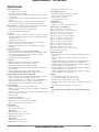
EZ-ZONE® ST
User’s Manual
Integrated Control Loop
TOTAL
CUSTOMER
SATISFACTION
3 Year Warranty
ISO 9001
Registered Company
1241 Bundy Boulevard., Winona, Minnesota USA 55987
Phone: +1 (507) 454-5300, Fax: +1 (507) 452-4507 http://www.watlow.com
0600-0052-0000 Rev. F
January 2010
Winona, Minnesota USA
Made in the U.S.A.
www.anderson-bolds.com
Anderson-Bolds ~ 216-360-9800
Safety Information
Warranty
We use note, caution and warning symbols throughout
this book to draw your attention to important operational and safety information.
The EZ-ZONE® ST is manufactured by ISO 9001-registered processes and is backed by a three-year warranty to the first purchaser for use, providing that the
units have not been misapplied. Since Watlow has no
control over their use, and sometimes misuse, we cannot guarantee against failure. Watlow's obligations
hereunder, at Watlow's option, are limited to replacement, repair or refund of purchase price, and parts
which upon examination prove to be defective within
the warranty period specified. This warranty does not
apply to damage resulting from transportation, alteration, misuse or abuse.
A “NOTE” marks a short message to alert you to an
important detail.
A “CAUTION” safety alert appears with information
that is important for protecting your equipment and
performance. Be especially careful to read and follow all
cautions that apply to your application.
A “WARNING” safety alert appears with information
that is important for protecting you, others and equipment from damage. Pay very close attention to all warnings that apply to your application.
The safety alert symbol, ç (an exclamation point in
a triangle) precedes a general CAUTION or WARNING
statement.
The electrical hazard symbol, Ó (a lightning bolt in a
triangle) precedes an electric shock hazard CAUTION or
WARNING safety statement.
ç
Ó
CAUTION or WARNING
Electrical Shock Hazard
CAUTION or WARNING
Warranty
The EZ-ZONE™ ST is manufactured by ISO 9001-registered processes and is backed by a three-year warranty
to the first purchaser for use, providing that the units
have not been misapplied. Since Watlow has no control
over their use, and sometimes misuse, we cannot guarantee against failure. Watlow’s obligations hereunder,
at Watlow’s option, are limited to replacement, repair or
refund of purchase price, and parts which upon examination prove to be defective within the warranty period
specified. This warranty does not apply to damage resulting from transportation, alteration, misuse or abuse. The
purchaser must use Watlow parts to maintain all listed
ratings.
Technical Assistance
If you encounter a problem with your Watlow controller, review your configuration information to verify
that your selections are consistent with your application: inputs, outputs, alarms, limits, etc. If the problem persists, you can get technical assistance from
your local Watlow representative (see back cover), by
e-mailing your questions to wintechsupport@watlow.
com or by dialing +1 (507) 494-5656 between 7 a.m.
and 5 p.m., Central Standard Time (CST). Ask for for
an Applications Engineer. Please have the following
information available when calling:
• Complete model number
• All configuration information
• User’s Manual
• Factory Page
Return Material Authorization (RMA)
1. Call Watlow Customer Service, (507) 454-5300,
for a Return Material Authorization (RMA) number
before returning any item for repair. If you do not
know why the product failed, contact an Application
Engineer or Product Manager. All RMA’s require:
• Ship-to address
• Bill-to address
• Contact name
• Phone number
• Method of return shipment
• Your P.O. number
• Detailed description of the problem
• Any special instructions
• Name and phone number of person returning the
product.
2. Prior approval and an RMA number from the
Customer Service Department is required when
returning any product for credit, repair or evaluation. Make sure the RMA number is on the outside of
the carton and on all paperwork returned. Ship on a
Freight Prepaid basis.
3. After we receive your return, we will examine it and
try to verify the reason for returning it.
4. In cases of manufacturing defect, we will enter
a repair order, replacement order or issue credit for
material returned. In cases of customer mis-use, we
will provide repair costs and request a purchase order
to proceed with the repair work.
5. To return products that are not defective, goods
must be be in new condition, in the original boxes and
they must be returned within 120 days of receipt. A 20
percent restocking charge is applied for all returned
stock controls and accessories.
6. If the unit is not repairable, you will receive a letter of explanation. and be given the option to have the
unit returned to you at your expense or to have us
scrap the unit.
7. Watlow reserves the right to charge for no trouble
found (NTF) returns.
The EZ-ZONE® ST User’s Manual is copyrighted by
Watlow Electric, Inc., © January 2010 with all rights
reserved.
EZ-ZONE® ST is covered by U.S. Patent No. 6,005,577
and Patents Pending
www.anderson-bolds.com
Anderson-Bolds ~ 216-360-9800
TC
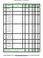
Table of Contents
Chapter 1: Overview . . . . . . . . . . . . . . . . . . . . . . . . . . . . . . . . . . . . .
The EZ-ZONE® ST Provides Total Thermal System Control . . . . . . . . . . . . . .
A Conceptual View of the ST. . . . . . . . . . . . . . . . . . . . . . . . . . . . . . . . . . . . . .
Getting Started Quickly. . . . . . . . . . . . . . . . . . . . . . . . . . . . . . . . . . . . . . . .
3
3
4
5
Chapter 2: Install, Wire and Set Address . . . . . . . . . . . . . . . . . . . . . . . 7
Wiring . . . . . . . . . . . . . . . . . . . . . . . . . . . . . . . . . . . . . . . . . . . . . . . . . . . . . . . 9
Installation. . . . . . . . . . . . . . . . . . . . . . . . . . . . . . . . . . . . . . . . . . . . . . . . . . . 14
Replacing the Solid-State Relay . . . . . . . . . . . . . . . . . . . . . . . . . . . . . . . . . . 15
ST Isolation Block. . . . . . . . . . . . . . . . . . . . . . . . . . . . . . . . . . . . . . . . . . . . . 17
Setting the Address. . . . . . . . . . . . . . . . . . . . . . . . . . . . . . . . . . . . . . . . . . . . 26
Conventions Used in the Menu Pages. . . . . . . . . . . . . . . . . . . . . . . . . . . . . . 27
Chapter 3: Operations Pages . . . . . . . . . . . . . . . . . . . . . . . . . . . . . .
Analog Input Menu . . . . . . . . . . . . . . . . . . . . . . . . . . . . . . . . . . . . . . . . . . . .
Digital Input/Output Menu. . . . . . . . . . . . . . . . . . . . . . . . . . . . . . . . . . . . . . .
Limit Menu. . . . . . . . . . . . . . . . . . . . . . . . . . . . . . . . . . . . . . . . . . . . . . . . . . .
Monitor Menu . . . . . . . . . . . . . . . . . . . . . . . . . . . . . . . . . . . . . . . . . . . . . . . .
Loop Menu. . . . . . . . . . . . . . . . . . . . . . . . . . . . . . . . . . . . . . . . . . . . . . . . . . .
Alarm Menu. . . . . . . . . . . . . . . . . . . . . . . . . . . . . . . . . . . . . . . . . . . . . . . . . .
Current Menu. . . . . . . . . . . . . . . . . . . . . . . . . . . . . . . . . . . . . . . . . . . . . . . . .
Profile Status Menu. . . . . . . . . . . . . . . . . . . . . . . . . . . . . . . . . . . . . . . . . . . .
30
31
32
32
32
33
35
36
37
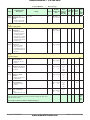
Chapter 4: Setup Pages. . . . . . . . . . . . . . . . . . . . . . . . . . . . . . . . . .
Analog Input Menu . . . . . . . . . . . . . . . . . . . . . . . . . . . . . . . . . . . . . . . . . . . .
Digital Input/Output Menu. . . . . . . . . . . . . . . . . . . . . . . . . . . . . . . . . . . . . . .
Limit Menu. . . . . . . . . . . . . . . . . . . . . . . . . . . . . . . . . . . . . . . . . . . . . . . . . . .
Control Loop Menu. . . . . . . . . . . . . . . . . . . . . . . . . . . . . . . . . . . . . . . . . . . .
Output Menu. . . . . . . . . . . . . . . . . . . . . . . . . . . . . . . . . . . . . . . . . . . . . . . . .
Alarm Menu. . . . . . . . . . . . . . . . . . . . . . . . . . . . . . . . . . . . . . . . . . . . . . . . . .
Current Menu. . . . . . . . . . . . . . . . . . . . . . . . . . . . . . . . . . . . . . . . . . . . . . . . .
Function Key . . . . . . . . . . . . . . . . . . . . . . . . . . . . . . . . . . . . . . . . . . . . . . . . .
Global Menu. . . . . . . . . . . . . . . . . . . . . . . . . . . . . . . . . . . . . . . . . . . . . . . . . .
Communications Menu. . . . . . . . . . . . . . . . . . . . . . . . . . . . . . . . . . . . . . . . .
39
40
42
44
44
47
48
50
51
52
53
Chapter 5: Profiling Page. . . . . . . . . . . . . . . . . . . . . . . . . . . . . . . . . 54
Wat low EZ-ZONE ® ST
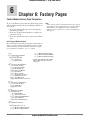
Chapter 6: Factory Pages. . . . . . . . . . . . . . . . . . . . . . . . . . . . . . . . .
Custom Setup Menu . . . . . . . . . . . . . . . . . . . . . . . . . . . . . . . . . . . . . . . . . . .
Security Setting Menu. . . . . . . . . . . . . . . . . . . . . . . . . . . . . . . . . . . . . . . . . .
Security Setting Menu. . . . . . . . . . . . . . . . . . . . . . . . . . . . . . . . . . . . . . . . . .
Diagnostics Menu . . . . . . . . . . . . . . . . . . . . . . . . . . . . . . . . . . . . . . . . . . . . .
Calibration Menu. . . . . . . . . . . . . . . . . . . . . . . . . . . . . . . . . . . . . . . . . . . . . .
59
60
60
62
62
63
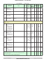
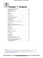
Chapter 7: Features. . . . . . . . . . . . . . . . . . . . . . . . . . . . . . . . . . . . .
Saving and Restoring User Settings . . . . . . . . . . . . . . . . . . . . . . . . . . . . . . .
Tuning the PID Parameters . . . . . . . . . . . . . . . . . . . . . . . . . . . . . . . . . . . . . .
Inputs. . . . . . . . . . . . . . . . . . . . . . . . . . . . . . . . . . . . . . . . . . . . . . . . . . . . . . .
Control Methods . . . . . . . . . . . . . . . . . . . . . . . . . . . . . . . . . . . . . . . . . . . . . .
Alarms. . . . . . . . . . . . . . . . . . . . . . . . . . . . . . . . . . . . . . . . . . . . . . . . . . . . . .
Using Lockout to Hide Pages and Menus . . . . . . . . . . . . . . . . . . . . . . . . . . .
64
65
65
66
68
72
73
• 1 •
www.anderson-bolds.com
Table of Contents
Anderson-Bolds ~ 216-360-9800
TC
Table of Contents (cont.)
Modbus - Using Programmable Memory Blocks. . . . . . . . . . . . . . . . . . . . . . 75
CIP - Communications Capabilities. . . . . . . . . . . . . . . . . . . . . . . . . . . . . . . . 75
Software Configuration . . . . . . . . . . . . . . . . . . . . . . . . . . . . . . . . . . . . . . . . . 76
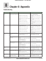
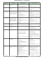
Chapter 8: Appendix . . . . . . . . . . . . . . . . . . . . . . . . . . . . . . . . . . . .
Troubleshooting. . . . . . . . . . . . . . . . . . . . . . . . . . . . . . . . . . . . . . . . . . . . . . .
Modbus - Programmable Memory Blocks. . . . . . . . . . . . . . . . . . . . . . . . . . .
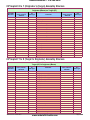
CIP Implicit O to T (Originator to Target) Assembly Structure. . . . . . . . . . .
CIP Implicit T to O (Target to Originator) Assembly Structure. . . . . . . . . . .
Specifications. . . . . . . . . . . . . . . . . . . . . . . . . . . . . . . . . . . . . . . . . . . . . . . . .
Ordering Information. . . . . . . . . . . . . . . . . . . . . . . . . . . . . . . . . . . . . . . . . . .
Index. . . . . . . . . . . . . . . . . . . . . . . . . . . . . . . . . . . . . . . . . . . . . . . . . . . . . . .
Declaration of Conformity. . . . . . . . . . . . . . . . . . . . . . . . . . . . . . . . . . . . . . .
How to Reach Us. . . . . . . . . . . . . . . . . . . . . . . . . . . . . . . . . . . . . . . . . . . . . .
Wat low EZ-ZONE ® ST
• 2 •
www.anderson-bolds.com
79
79
82
84
84
85
86
89
93
95
Table of Contents
Anderson-Bolds ~ 216-360-9800
1
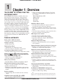
Chapter 1: Overview
The EZ-ZONE® ST Provides Total Thermal System Control
The EZ-ZONE ST solid-state controller offers complete thermal system control in a single package
while reducing system complexity and the cost of
control-loop ownership. You can order a PID controller already connected to a high-amperage, solid-state
relay capable of zero cross or phase angle firing with
the option of adding a properly sized heat sink, an
over-under temperature limit, a shut-down power
contactor, and digital communications in one package.
It just got a whole lot easier to solve the thermal
requirements of your system. Because the EZ-ZONE
ST along with the entire family of EZ-ZONE controls
are highly scalable where you pay only for what you
need. So if you are looking for a PID controller with
high amperage outputs, an over-under limit controller
or an integrated controller, the EZ-ZONE ST is the
answer.
Features and Benefits
Back panel or DIN rail mount
• Provides several mounting options
Compact package
• Reduces panel size
Touch-safe package
• IP2X-Touch safe with back of hand
• Increases safety for installers and operators
±0.1 percent temperature accuracy
• Provides efficient and accurate temperature control
Agency approvals:
(with factory-installed
heatsink);
(without factory-installed heatsink); CE; RoHS; W.E.E.E.; CSA
• Limit version features FM approval
• Provides third-party recognition
Three-year warranty
• Provides Watlow reliability and product support
Off-the-shelf designed system solution
• Improves system reliability and reduces wiring
• Reduces installation cost
• Eliminates compatibility headaches often encoun-
tered when using many different components and brands
Profile capability
• Includes ramp and soak with four files and forty
steps
• When used with the optional Remote User Inter
face/Gateway (RUI/GTW) the following protocols are available:
- EIA 232/485 Modbus RTU
- Modbus TCP
- EtherNet/IP
- DeviceNet
- Profibus DP
Solid-State Relay output
• Provides faster cycling, more precise control, in-
creased heater life and energy efficiency
• Resistive or inductive load current of up to 75 am-
peres using either zero-cross or phase angle control
modes
• Soft start feature with phase angle control mode to prevent load failure or blowing fuses
PID temperature control
• Provides accurate temperature control
• Provides a single input and dual outputs
• Provides standard or adaptive (TRU-TUNE+) PID tuning algorithms.
Optional temperature limit
• Increases safety during under and over-tempera-
ture conditions
Optional definite purpose mechanical contactor
• Enables circuit safety shutdown driven by a limit controller or a PID alarm output signal
Optional current monitoring feature
• Detects heater current flow and alarm indication of
failed Solid-State Relay or a heater zone
Optional Solid-State Relay heat sink
• Sized and engineered for specific applications
• Factory assembled heat sink required for UL listing
System diagnostics
• Provides continuous system level monitoring with alerts reducing the overall cost for maintenance ad service
Advanced controllability algorithms
• TRU-TUNE+™ meets demanding controllability requirements.
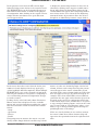
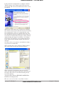
PC Software: EZ-ZONE ST Configurator
• Wizard-style configuration of controller settings
• Online or offline recipe editing
UL® is a registered trademark of Underwriter’s Laboratories Inc.
Modbus™ is a trademark of Schneider Automation Incorporated.
Communications with PLC, PC or HMI
• ST with optional Modbus® RTU protocol
Wat low EZ-ZONE ® ST
• 3 •
www.anderson-bolds.com
Chapter 1 Over view
Anderson-Bolds ~ 216-360-9800
A Conceptual View of the ST
The flexibility of the ST software and hardware allows
a large range of configurations. Acquiring a better
understanding of the controller's overall functionality
and capabilities while at the same time planning out
how the controller can be used will deliver maximum
effectiveness in your application.
It is useful to think of the controller in terms of
functions; there are internal and external functions.
An input and an output would be considered external functions where the PID calculation would be an
internal function. Information flows from an input
function to an internal function to an output function
when the controller is properly configured. A single
ST control can carry out several functions at the same
time. For instance, closed-loop control monitoring for
several different alarm situations, while at the same
time operating switched devices, such as lights and
motors. Each process needs to be thought out carefully
and the controller’s various functions set up properly.
Inputs Functions
The inputs provide the information that any given
programmed procedure can act upon. In a simple form,
this information may come from an operator pushing
a button or as part of a more complex procedure it
may represent a remote set point being received from
another controller.
Each analog input typically uses a thermocouple
or RTD to read the temperature of something. It can
also read volts, current or resistance, allowing it to
use various devices to read humidity, air pressure,
operator inputs and others values. The settings in the
Analog Input Menu (Setup Page) for each analog input
must be configured to match the device connected to
that input.
Each digital input reads whether a device is active or inactive. A controller with digital input-output
(DIO) hardware includes two sets of terminals each.
Each DIO must be configured to function as either an
input or output with the Direction parameter in the
Digital Input/Output Menu (Setup Page).
The EZ-ZONE Remote User Interface (RUI) has a
function, or EZ Key on the front panel, this too can be
configured as a digital input by toggling the function
assigned to it in the Digital Input Function parameter
in the Function Key Menu (Setup Page). If interested
in learning more about the RUI and how it is used
with the ST retrieve the RUI user manual from the
Watlow web site. Point your browser to:
set a state to true or false, or reading a temperature to
set an alarm state to on or off. Or, it could compare the
temperature of a process to the set point and calculate
the optimal power for a heater.
To set up a function, it’s important to tell it what
source, or instance, to use. For example, an alarm may
be set to respond to either analog input 1 or 2 (instance 1 or 2, respectively).
Outputs Functions
Outputs can perform various functions or actions in
response to information provided by a function, such
as operating a heater, driving a compressor, turning a
light on or off, unlocking a door, turning on a buzzer
etc...
Assign an output to a Function in the Output
Menu or DIO Menu. Then select which instance of
that function will drive the selected output. For example, you might assign an output to respond to alarm 2
(instance 2).
You can assign more than one output to respond to
a single instance of a function. For example, alarm 2
could be used to trigger a light connected to output 1
and a siren connected to digital output 5.
Input Events and Output Events
Input and output events are internal states that are
used exclusively by profiles. The source of an event
input can come from a real-world digital input or an
output from another function. Likewise, event outputs
may control a physical output such as an output function block or be used as an input to another function.
http://www.watlow.com/literature/pti_search.cfm?dltype=5
Once there, type in EZ-ZONE for a keyword at the
bottom of the page and then click on the search button
to find the user manual.
Internal Functions
Functions use input signals to calculate a value. A
function may be as simple as reading a digital input to
Wat low EZ-ZONE ® ST
• 4 •
www.anderson-bolds.com
Chapter 1 Over view
Anderson-Bolds ~ 216-360-9800
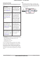
Getting Started Quickly
The ST control has a page and menu structure that is
listed below along with a brief description of its purpose.
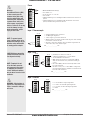
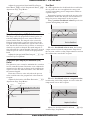
Setup Page
Push and hold the up
and down keys (¿ ¯)
for 6 seconds to enter.
(See the Setup Page for
further information)
Once received, a user
would want to setup
their control prior to operation. As an example,
define the input type
and set the output cycle
time.
Operations Page
Push and hold the up
and down keys (¿ ¯)
for 3 seconds to enter.
(See the Operations
Page for further information)
After setting up the control to reflect your equipment, the Operations
Page would be used
to monitor or change
runtime settings. As an
example, the user may
want to see how much
time is left in a profile
step or perhaps change
the autotune set point.
Factory Page
Push and hold the Infinity and the green
Advance keys (ˆ ‰) for
6 seconds to enter. (See
the Factory Page for further information)
For the most part the
Factory Page has no
bearing on the control
when running. Here, a
user may want to enable
password protection,
view the control part
number or perhaps create a custom Home Page.
Profile Page
Push and hold the the
green Advance key ‰ for
6 seconds to enter. (See
the Profile Page for further information)
If equipped with this
feature, a user would
want to go here to configure a profile.
Note:
The output cycle time will have a bearing on the
life of mechanical relay outputs and can be different based on the type of output ordered. The output
cycle time can be changed in the Setup Page under
the Output Menu.
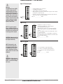
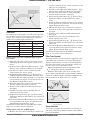
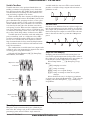
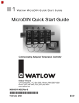
EZ-ZONE ST Default Configuration
Input
Function
Input Sensor
Analog Input 1
Thermocouple Type J
PID
Controller
Heat
Output
Function
Output 1
Heat
Loop 1
The default ST loop configuration out of the box is
shown below:
• Analog Input functions set to thermocouple, type J
• Heat algorithm set for PID, Cool set to off
• Output 1 set to Heat
• Control mode set to Auto
• Set point set to 75 °F
If you are using the input type shown above, simply
connect your input and output devices to the control.
Power up the control and push the up arrow ¿ on
the face of the control to change the set point from
the default value of 75 °F to the desired value. As the
Set Point increases above the Process Value, output 1
will come on and it will now begin driving your output
device.
Wat low EZ-ZONE ® ST
• 5 •
www.anderson-bolds.com
Chapter 1 Over view
Anderson-Bolds ~ 216-360-9800
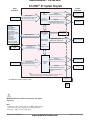
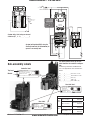
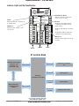
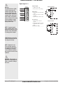
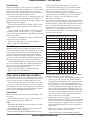
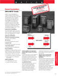
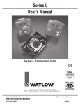
EZ-ZONE® ST System Diagram
Output
Functions
Input
Functions
Input Sensor
Analog Input 1
none, Thermocouple, RTD (100Ω,
1kΩ), Process (V, mV, mA)
PID
Controller
Output 1
Solid State Relay (form A)
off, heat, cool
(Optional Ramp/Soak max 4
Output 2
files, 40 steps) 5A Mechanical Relay (form A), or
off, heat, cool
alarm, event
0.5A Solid State Relay (form A)
- None
- Limit reset
- Profile start/stop
- Profile start
- Profile hold/resume
- Profile disable
- TRU-TUNE+® disable
- Switch Control Loop Off
- Manual mode
- Tune
- Idle set point
- Force alarm
- Loop & alarms off
- Silence alarm
- Alarm clear, request
- Restore user settings
Digital Input 5 & 6
(optional) DC voltage, Dry Contact
Supervisory &
Power Board
*RUI, EZ-ZONE
Controllers, PLC, PC
or HMI
Input Sensor
EIA-485 Communication
Standard Bus
(optional Modbus RTU)
Analog Input 2
none, Thermocouple, RTD (100Ω,
1kΩ), Process (V, mV, mA)
Current Sensor
(optional)
Standard Bus
Zone Address
1 - 16
Digital Output 5 & 6
(optional) none, switched dc
off, heat, cool,
alarm, event, limit
Output 3
5A Mechanical Relay (form C)
off, heat, cool,
event, limit, alarm
Modbus
Address 1 - 247
Limit Controller
Board
(optional)
Output 4
5A Mechanical Relay (form A)
Limit
If Limit, this output must
be Limit
Note:
Number of inputs and outputs and various combinations of the same will vary
depending upon part number; see ordering matrix for more detail.
Contactor
(optional)
* EZ-ZONE Remote User Interface (RUI)
High
Current
Power
Ó
WARNING: When the controller is powered up, the outputs
may turn on.
Note:
A current error can be sent to the RUI (Remote User
Interface) soft error display by enabling Current
Reading [`CU;r] in the Setup Page.
Wat low EZ-ZONE ® ST
• 6 •
www.anderson-bolds.com
Chapter 1 Over view
Anderson-Bolds ~ 216-360-9800
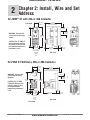
2
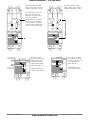
Chapter 2: Install, Wire and Set
Address
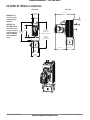
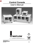
EZ-ZONE® ST with 25A or 40A Contactor
36.2 mm
(1.43 in)
Front View
156 mm
(6.14 in)
25 A heatsink (shown)
This dimension same for 40 A heatsink.
41.9 mm
(1.65 in)
4
1
35 mm
(1.38 in)
EZ-ZONE™ ST
Patent Pending
WARNING: The heat sink
can become hot during operation.
Integrated
Control Loop
177.8 mm
(7.00 in)
2
CAUTION: The EZ-ZONE ST
must be mounted vertically
(as shown) to meet the ampere/ambient-temperature
performance curve.
3
EZ-ZONE™ ST
Patent Pending
Integrated
Control Loop
188.6 mm
(7.43 in)
5
4
1
2
5
6
63.5 mm
(2.5 in)
25 A (shown)
98.6 mm
(3.88 in)
40 A
3
126.1 mm
(4.97 in)
6
29.5 mm
(1.16 in)
Side View
EZ-ZONE ST Without a 25A or 40A Contactor
51.6 mm
(2.03 in)
36.2 mm
(1.43 in)
156 mm
(6.14 in)
25 A heatsink
156 (shown)
mm
(6.14for
in) 40 A heatsink.
This dimension the same
36.2 mm
51.6 mm
(2.03 in)
(1.43 in)
WARNING: The heat sink
can become hot during
operation.
177.8 mm
in)
CAUTION: The(7.00
EZ-ZONE
mm
ST must be mounted 87
verti(3.43 in)
cally (as shown) to meet
the ampere/ambienttemperature performance
curve.
#8 mounting
screw
1 mm
177.8
(7.00 in)
2
EZ-ZONE™ ST
Integrated Control Loop
Patent Pending
#8 mounting
screw
1
#8 mounting
screw
35 mm
in)
#8 mounting
screw
35 mm
(1.38(1.38
in)
2
188.6 mm
188.6 mm
(7.43 in) (7.43 in)
EZ-ZONE™ ST
Integrated Control Loop
63.5 mm
(2.5 in)
25 A (shown)
2
12
1
Patent Pending
EZ-ZONE™ ST
Integrated Control Loop
Patent Pending
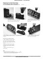
98.6 Front
mm
(3.88 in)
40 A
Watlow EZ-ZONE ® ST
41.9 mm
in)
(1.65
41.9
mm
(1.65 in)
EZ-ZONE™ ST
Integrated Control Loop
Patent Pending
87 mm
(3.43 in)
17.4 mm
(0.68 in)
17.4 mm
(0.68 in)
25 A heatsink (shown)
This dimension the same for 40 A heatsink.
63.5 mm
(2.5 in)
25 A (shown)
98.6 mm
(3.88 in)
40 A
View
126.1 mm
(4.97 in)
126.1 mm
(4.97 in)
29.5 mm
(1.16 in)
29.5 mm
(1.16 in)
Side View
• 7 •
www.anderson-bolds.com
Chap ter 2 Install and Wire
Anderson-Bolds ~ 216-360-9800
EZ-ZONE ST Without a Contactor
Front View
215.1 mm
(8.47 in)
51.6 mm
(2.03 in)
WARNING: The
heat sink can become hot during
operation.
CAUTION: The
EZ-ZONE ST must
be mounted vertically (as shown) to
meet the ampere/
ambient-temperature performance
curve.
Side View
46 mm
(1.18 in)
39.9 mm
(1.57 in)
35 mm
(1.38 in)
87 mm
(3.43 in)
197.1 mm
(7.76 in)
with 120 and
240Vac fan (shown)
138.5 mm
(5.45 in)
184.4 mm
(7.26 in)
with 24 Vdc fan
28.1 mm
(1.11 in)
48 mm
(1.89 in)
126.5 mm
(4.98 in)
89.2 mm
(3.51 in)
80 mm
(3.15 in)
Wat low EZ-ZONE ® ST
• 8 •
www.anderson-bolds.com
Chapter 2 Install and Wire
Anderson-Bolds ~ 216-360-9800
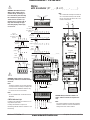
Wiring
with a contactor (ST _ _ - (B or F) _ _ _ - _ _ _ _)
Ó
L3
K3
J3
A1
L4
T2
T2
L4
A1
J3
K3
L3
T2
L4
A1
J3
K3
L3
S2
S2
S1
EZ-ZONE™ ST
S2
Patent Pending
L3
K3
J3
A1
L4
T2
ST_ L - _ _ _ _ - _ _ _ _ (with limit)
OUT 3
LIMIT
SSR
ON
OUT 2
STATUS
common (RUI)
OUT 2
CF
T+/R+ (RUI)
T-/R- (RUI)
ON
1234
98
99
3
6
fuse
Output 1 (SSR)
Power Supply
ST_ _ - _ _ A _ - _ _ _ _
Remote User Interface (RUI)
earth
ground
98
99
CC
CA
CB
B5
T-/R- (Modbus RTU)
common (Modbus RTU)
T+/R+ (Modbus RTU)
- common (Digital I/O)
Watlow EZ-ZONE ® ST
OUT 3
CD
- common (Digital I/O)
No flashing indicates that the controller is not
functioning.
+ Digital Input 5 or Output 5
Flashing red indicates an input error.
+ Digital Input 6 or Output 6
Flashing green indicates the controller is running with no input errors.
D6
STATUS Indicator Light
D5
Note:
Use the contactor with a minimum load of
100 watts.
SSR
CE
+ Digital Input 6 or Output 6
Note:
Terminals L4 and A1 on the limit connector
are jumpered at the factory to complete the
contactor circuit. Additional switches may
be wired in series to the terminals.
STATUS
L2
B5
+ Digital Input 5 or Output 5
WARNING: If high voltage is applied to a
low-voltage controller, irreversible damage
will occur.
5
LIMIT
A1
T1
K2
D6
Address
Selection
ç
2
L3
L4
D5
K3
T2
S1
J3
–
S2
L2
K2
S1
T1
R1
+
R1
N.O. (Output 4)
contactor (Coil 1)
N.C. (Output 3)
common (Output 3)
N.O. (Output 3)
1234
S2
Integrated
Control Loop
common
(Output 2) N.O.
(Output 2)
Controller
4
1
S3
R2
L2
K2
T1
S1
R1
Limit
fuse
S3
R2
L2
K2
T1
S1
R1
–
S2
L2
K2
T1
S1
R1
S3
+
+
Thermocouple
(Input 2)
S2
Thermocouple
(Input 1)
–
S1
3-wire
RTD
(Input 2)
S3
–
R2
2-wire
RTD
(Input 2)
hot
neutral
+
R2
+
S1
A1
Process
0 to 10VÎ (dc)
0 to 50mVÎ (dc)
(Input 2)
L2
K2
T1
S1
R1
2-wire
RTD S1
(Input 1)
hot
fuse
fuse
Process
0 to 20 mA
(Input 2)
–
Contactor
Coil 1
hot
–
Process
0 to 20 mA
(Input 1)
3-wire
RTD
(Input 1)
Contactor
Coil 2
R2
Process
0 to 10VÎ (dc)
0 to 50mVÎ (dc)
+
(Input 1)
Note:
A2 is connected internally to terminal 98.
A1 is connected internally to the contactor coil. The other side of the coil is connected to terminal 99.
ST_ B - _ _ _ _ - _ _ _ _ (no limit)
A2
WARNING: Use National Electric
(NEC) or other country-specific
standard wiring and safety practices when wiring and connecting
this controller to a power source
and to electrical sensors or peripheral devices. Failure to do so
may result in damage to equipment and property, and/or injury
or loss of life.
fuse
Power Supply
load
CAUTION: Always mount the controller as
shown, with the heat-sink fins aligned vertically.
Note:
The control common terminal and the digital
common terminal are referenced to different
voltages and must remain isolated.
ST_ _ - _ _ M _ - _ _ _ _
Modbus RTU on EIA-485
• 9 •
www.anderson-bolds.com
Chap ter 2 Install and Wire
Anderson-Bolds ~ 216-360-9800
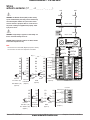
Wiring
without a contactor (ST _ _ - A _ _ _ _ - _ _ _ _ )
hot
Ó
hot
fuse
fuse
WARNING: Use National Electric (NEC) or other countryspecific standard wiring and safety practices when wiring
and connecting this controller to a power source and to
electrical sensors or peripheral devices. Failure to do so
may result in damage to equipment and property, and/or
injury or loss of life.
load
Output 1 (SSR)
neutral
ç
hot
fuse
load
Output 1 (SSR)
WARNING: If high voltage is applied to a low-voltage controller, irreversible damage will occur.
1
CAUTION: Always mount the controller as shown, with the
heat-sink fins aligned vertically.
2
EZ-ZONE™ ST
Integrated Control Loop
Note:
If 75A heat sink is ordered D6 (Digital Input) will be factory
set and used as the SSR over temperature shut-down.
Patent Pending
Indicator
Lights
SSR
LIMIT
STATUS
K3
L3
L3
K3
K3
K3
J3
J3
J3
J3
A1
A1
A1
L4
L4
L4
T2
+ T2
- S2
T2
S2
T2
S3
S2
S3
S2
S1
R2
S1
R2
- S2
+ R2
R2
N.O. (Output 3)
L3
common (Output 3)
Address
Selection
K3
OUT 2
1234
L3
Limit
ST_ L - _ _ _ _ - _ _ _ _
all
ON
L3
OUT 3
98
99
J3
Control
CF
common (RUI)
A1
contactor (Coil 1)
A1
L2
CD
T-/R- (RUI)
L4
N.O. (Output 4)
L4
K2
CE
T+/R+ (RUI)
T2
T1
B5
- common (Digita
-
S2
S1
D6
+ Digital Input 6 o
+
R2
R1
D5
+ Digital Input 5 o
Thermocouple
(Input 2)
Controller
K2
L2
+
T1
S1
R1
-
L2
K2
T1
K2
S2
T1
S1
S3
R1
S1
Process
Process
0 to 10VÎ (dc) 0 to 20 mA
0 to 50mVÎ (dc) (Input 1)
(Input 1)
Wat low EZ-ZONE ® ST
L2
K2
+
Power
N.C. (Output 3)
2-wire
3-wire
Process
Process
RTD
0 to 10VÎ (dc) 0 to 20 mA
(Input 2)
0 to 50mVÎ (dc) (Input 2)
(Input 2)
L2
Power
2-wire
S1
S3
R1
S1
3-wire
RTD
(Input 1)
N.O. (Output 2)
common (Output 2)
L2
K2
T1
T1
S1
R1
-
S1
+
R1
Thermocouple
(Input 1)
• 10 •
www.anderson-bolds.com
Chapter 2 Install and Wire
S
R
(R
Anderson-Bolds ~ 216-360-9800
hot
hot
fuse
fuse
load
Output 1 (SSR)
neutral
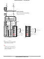
Ground Connection
hot
Connect the ground to the heat sink.
There is no ground connection on models without a heat sink.
fuse
load
Output 1 (SSR)
1
2
EZ-ZONE™ ST
Integrated Control Loop
Patent Pending
Indicator
Lights
SSR
LIMIT
STATUS
OUT 3
Limit
Address
Selection
1234
L3
ON
N.O. (Output 3)
OUT 2
98
Power
98
Power
Power
99
Power
CC
common (Modbus RTU)
CA
T-/R- (Modbus RTU)
CB
T+/R+ (Modbus RTU)
ommon (Output 3)
K3
N.C. (Output 3)
J3
Control
CF
common (RUI)
contactor (Coil 1)
A1
L2
CD
T-/R- (RUI)
N.O. (Output 4)
L4
K2
CE
T+/R+ (RUI)
T2
T1
B5
- common (Digital I/O)
B5
- common (Digital I/O)
-
S2
S1
D6
+ Digital Input 6 or Output 6
D6
+ Digital Input 6 or Output 6
+
R2
R1
D5
+ Digital Input 5 or Output 5
D5
+ Digital Input 5 or Output 5
99
ST_ _ - _ _ A _ - _ _ _ _
Remote User Interface
(RUI)
ST_ _ - _ _ M _ - _ _ _ _
Modbus RTU on EIA-485
Thermocouple
(Input 2)
Controller
Note:
The
control
terminal and the digital
N.O.
(Outputcommon
2)
L2 common terminal L2
are referenced to different
common
(Output
2)
voltages
and must
remain isolated.
K2
K2
S2
T1
T1
S1
S3
S1 Note:
If 75A heat
+ sink is ordered D6
R1will be factory set
S1
R1 (Digital Input)
3-wire
Thermocouple
and used as the SSR over temD
(Input 1) shut-down.
perature
ut 1)
Watlow EZ-ZONE ® ST
• 11 •
www.anderson-bolds.com
Chap ter 2 Install and Wire
Anderson-Bolds ~ 216-360-9800
1
Internal wiring in an ST
with a single-pole contactor
without a limit (ST _ B - B _
_ _ - _ _ _ _).
4
Use single-pole contactors
for hot-to-neutral loads.
NEC does not permit neutral to be switched.
contactor
contact
2
Use double-pole contactors
for hot-to-hot loads. Both
hot legs must be opened together on limit conditions to
remove power from circuit.
5
current
sensor
SSR
1
4
contactor
contacts
2
5
current
sensor
SSR
to pin 3 to pin 6
below
below
to pin 3 to pin 6
below below
Limit
A1
A2
Limit
A1
A2
1
1
4
contactor
coil
SSR
user-supplied
safety switch
to pin 3
below
to pin 6
below
current
sensor
SSR
to pin 3 to pin 6
below below
contactor
coil
You can use output 2
(L2 and K2) to deactivate the contactor coil
on an ST without a
limit (ST _ B - _ _ _ _
- _ _ _ _).
(Dotted lines represent internal wiring.)
Power
98
99
Power
98
99
(Dotted lines represent internal wiring.)
3
Wat low EZ-ZONE ® ST
Limit
L2
K2
You may remove
the factory-installed
jumper between A1
and L4 to install a
safety switch for the
limit relay (ST _ L - _
_ _ _ - _ _ _ _).
5
A1
A2
Limit
A1
L4
contactor
coil
3
Power
98
99
Power
98
99
2
5
output 4
internal relay
normally open
contactor
contact
6
3
2
current
sensor
4
contactor
coil
6 contactor
contact
3
Internal wiring in an ST
with a double-pole contactor
without a limit (ST _ B - F _
_ _ - _ _ _ _).
6
6
• 12 •
www.anderson-bolds.com
Chapter 2 Install and Wire
Anderson-Bolds ~ 216-360-9800
1
2
hot
120VÅ (ac)
EZ-ZONE™ ST
Integrated Control Loop
neutral
Patent Pending
fuse
Do not switch or
fuse neutral wire!
fuse
SSR
LIMIT
STATUS
OUT 3
ON
98
1234
L3
K3
99
J3
N.O. (Output 4)
Power
Power
fuse
CF
A1
L2
CD
L4
K2
CE
T1
B5
S2
S1
D6
R2
R1
D5
T2
4
1
OUT 2
limit relay
contactor
coil
customer supplied
limit contactor
EZ-ZONE™ ST
Patent Pending
Integrated
Control Loop
20 A
maximum
2
1
L3
K3
J3
A1
L4
T2
–
S2
2
EZ-ZONE™ ST
Integrated Control Loop
Patent Pending
Address
Selection
STATUS
1234
K3
J3
ON
1234
6
OUT 2
ON
SSR
STATUS
L3
98
3
SSR
LIMIT
OUT 3
OUT 2
99
CF
B5
CD
D6
CE
D5
System (with optional RUI) using the
auxiliary terminals (20 A maximum) to
operate a secondary load.
LIMIT
OUT 3
L2
K2
T1
S1
R1
+
-
+
R2
System with a limit using an external
contactor (ST _ L - A _ _ _ - _ _ _ _).
+
-
5
98
99
CF
A1
L2
CD
L4
K2
CE
T2
T1
B5
S2
S1
D6
R2
R1
D5
earth
ground
zone 1
The model number at the top of each
label identifies the controller configuration.
Sub-assembly Labels
See Ordering Information and Model Numbers in the Appendix for more detailed information.
Controller label.
Top Level
Module
ST??-????-????
SEE MANUAL 0600-0052-0000
??? V~50/60 Hz 140VA MAX
ST _ _ - _ L _ _ - _ _ _ _ 24 to 28V ‡ (ac/dc)
ST _ _ - _ H _ _ - _ _ _ _ 100 to 240V ‡ (ac/dc)
ST _ _ - _ 1 _ _ - _ _ _ _ 24VÅ (ac)
ST _ _ - _ 2 _ _ - _ _ _ _ 120VÅ (ac)
ST _ _ - _ 3 _ _ - _ _ _ _ 208 to 240VÅ (ac)
STRC-0???-????
US PAT. 6005577;
DC:???? SN:?????? D553098; D555601; D555606
Heat sink label.
ST??-????-????
SCCR 200KA TYPE 2
SEE MANUAL
0600-0052-0000
STRT-HS??-000?
DC:????
SN:??????
SEE PATENT CHART
Patent Numbers
Base label.
Heat
Sink
ST??-????-????
ST??-????-B???
US PAT. 5598322;
D531138
ST??-????-C???
US PAT. 5598322;
D529874
ST??-A???-????
US PAT. D553581;
D558683
ST??-[B,F]??-????
US PAT. D553094;
D553099
SEE MANUAL
0600-0052-0000
STRT-BASE-????
DC:????
Watlow EZ-ZONE ® ST
SN:??????
SEE PATENT CHART
Base
• 13 •
www.anderson-bolds.com
Chap ter 2 Install and Wire
Anderson-Bolds ~ 216-360-9800
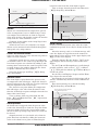
Installation
Mounting and Dismounting the Controller from a DIN Rail
To mount the controller on a DIN rail, first
hook the top flange on the back of the heat
sink on to the top of the DIN rail. Then
rotate the controller to an upright position
until the lower flange snaps into place.
To dismount the controller, first use a
screwdriver to pull down the small lever on the bottom of the heat sink and
rotate the bottom of the controller forward. Then lift the the controller off of
the rail.
Note:
Typically, the DIN rail is mounted before components are mounted on it.
Wat low EZ-ZONE ® ST
• 14 •
www.anderson-bolds.com
Chapter 2 Install and Wire
Anderson-Bolds ~ 216-360-9800
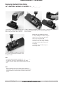
Replacing the Solid-State Relay
on a Controller without a Contactor (ST _ _-A _ _ _-_ _ _ _)
1. Pinch the release levers on the top and
bottom of the control module and lift the
bottom edge forward to detach the unit.
2. With a Phillips screwdriver, remove 3. Lift the controller body, exposing
the four nearest screws that were un- the solid-state relay.
der the module.
Replacing the Solid-State Relay
1. Using a Phillips screwdriver, replace
the two screws connecting the solidstate relay to the heat sink.
2. Place the controller body over the
solid-state relay and, using a Phillips
screwdriver, replace the four screws
securing it.
3. Snap the control module in place,
bottom edge first.
4. Using a Phillips screwdriver, remove the
two screws connecting the solid-state relay
to the heat sink.
Note:
For controller models without a contactor (ST _ _-A _ _ _-_ _ __),
the solid-state relay must be mounted with the larger power
terminals on the top and the smaller control terminals on the bottom.
Note:
Factory calibration is done using control and base modules as
matched pairs. Due to this fact, current detection (if turned on) may
not read accurately if a control module is placed into another base
module.
Watlow EZ-ZONE ® ST
• 15 •
www.anderson-bolds.com
Chap ter 2 Install and Wire
Anderson-Bolds ~ 216-360-9800
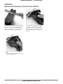
Replacing the Solid-State Relay
on a Controller with a Contactor (ST _ _ - (B or F) _ _ _ - _ _ _ _)
1. Pinch the release levers on the top and
bottom of the control module and lift the
right edge forward to detach the unit.
3. With a Phillips screwdriver, remove
the two screws at the top corners of the
controller.
4. Lift the controller body, exposing
the solid-state relay.
2. With a Phillips screwdriver, remove
the four nearest screws that were under
the module.
5. Using a Phillips screwdriver, remove
the two screws connecting the solidstate relay to the heat sink.
Replacing the Solid-state Relay
1. Using a Phillips screwdriver, replace
the two screws connecting the solidstate relay to the heat sink. Check that
the bottom of the solid-state relay is on
the left.
2. Place the controller body over the
solid-state relay and, using a Phillips
screwdriver, replace the six screw securing it.
3. Snap the control module in place,
left edge first.
Note:
For controller models with a contactor (ST _ _-A _ _ _-_ _ _ _), the solid-state relay must be mounted with the larger power terminals on
the right and the smaller control terminals on the left.
Wat low EZ-ZONE ® ST
• 16 •
www.anderson-bolds.com
Chapter 2 Install and Wire
Anderson-Bolds ~ 216-360-9800
Indicator Lights and Slot Identification
1
2
EZ-ZONE™ ST
Integrated Control Loop
Patent Pending
Solid-State Relay:
Indicates that the solid-state
relay is in an on state.
SSR
LIMIT
STATUS
Limit:
OUT 3
Indicates that the controller is
in a limit state.
L3
Indicates that output 3 is in
an on state.
K3
Address
Selection
1234
ON
Output 3:
Status:
OUT 2
98
99
Flashing green indicates the
controller is running with no
input errors.
Flashing red indicates an input
error.
J3
Control
CF
A1
L2
CD
L4
K2
CE
T2
T1
B5
Output 2:
S2
S1
D6
R2
R1
D5
Indicates that output 2 is in an
on state.
Slot A
Slot B
No flashing indicates that the
controller is not functioning.
Slot C
ST Isolation Block
Safety Isolation
Safety Isolation
Controller Power Supply
20 to 26VÎ (dc)
20 to 26VÅ (ac)
85 to 264VÅ (ac)
Mechanical Relay,
Solid-State Relay,
Outputs
No Isolation
Digital Inputs & Outputs
5-6
No Isolation
Analog Input 1
Low-voltage
Isolation
Analog Input 2
Low-voltage
Isolation
Communications Ports
Controller
Low Voltage Power Bus
Safety Isolation
Low-voltage Isolation: 42V peak
Safety Isolation: 2300VÅ (ac)
Watlow EZ-ZONE ® ST
• 17 •
www.anderson-bolds.com
Chap ter 2 Install and Wire
Anderson-Bolds ~ 216-360-9800
Ó
Warning:
Use National Electric (NEC)
or other country-specific
standard wiring and safety
practices when wiring and
connecting this controller to
a power source and to electrical sensors or peripheral
devices. Failure to do so may
result in damage to equipment and property, and/or
injury or loss of life.
Power
Slot C
98
99
power
power
fuse
CF
CD
CE
B5
D6
•
•
•
•
•
Minimum/Maximum Ratings
85 to 264VÅ (ac)
20.4 to 26.4 VÅ (ac) / VÎ (dc)
47 to 63 Hz
12VA maximum power consumption without mechanical contactor in
system
• 50VA maximum power consumption with mechanical contactor in
system, 140VA if using external contactor
D5
Power
Input 1 Thermocouple
Slot B
NOTE: To prevent ground
loops, isolation needs to be
maintained from input to output when using switched DC
or analog process outputs.
CAUTION: Always mount the
controller with the heat-sink
fins aligned vertically.
NOTE: Terminals L4 and
A1 on the limit connector
are jumpered at the factory
to complete the contactor
circuit. Additional switches
may be wired in series to the
terminals.
Ó
WARNING: If high voltage is
applied to a low-voltage controller, irreversible damage
will occur.
-
•
•
•
•
20 kΩ maximum source resistance
>20 MΩ input impedance
3 microampere open-sensor detection
Thermocouples are polarity sensitive. The negative lead (usually
red) must be connected to S1.
• To reduce errors, the extension wire for thermocouples must be
of the same alloy as the thermocouple.
ST _ _ - _ _ _ _ - _ _ _ _ (all)
S1
+
R1
Input 1 RTD
Slot B
S3
S1
Slot B
S2
T1
S1
S3
S1
R1
S1
R1
2-wire
3-wire
platinum, 100 and 1,000 Ω @ 0°C
calibration to DIN curve (0.00385 Ω/Ω/°C)
20 Ω maximum lead resistance
RTD excitation current of 0.09 mA typical. Each
ohm of lead resistance may affect the reading by
0.03°C.
• For 3-wire RTDs, the S1 lead (usually white) must
be connected to R1.
• For best accuracy use a 3-wire RTD to compensate
for lead-length resistance. All three lead wires must
have the same resistance.
ST _ _ - _ _ _ _ - _ _ _ _ (all)
Input 1 Process
Slot B
Slot B
- S1
+ T1
-
S1
+ R1
volts
Wat low EZ-ZONE ® ST
•
•
•
•
• 0 to 20 mA @ 100 Ω input impedance
• 0 to 10VÎ (dc) @ 20 kΩ input impedance
• 0 to 50 mVÎ (dc) @ 20 kΩ input impedance
• scalable
ST _ _ - _ _ _ _ - _ _ _ _ (all)
amperes
• 18 •
www.anderson-bolds.com
Chap ter 2 Install and Wire
Anderson-Bolds ~ 216-360-9800
Ó
Warning:
Use National Electric (NEC)
or other country-specific
standard wiring and safety
practices when wiring and
connecting this controller to
a power source and to electrical sensors or peripheral
devices. Failure to do so may
result in damage to equipment and property, and/or
injury or loss of life.
Input 2 Thermocouple
Slot A
•
•
•
•
-
20 kΩ maximum source resistance
>20 MΩ input impedance
3 microampere open-sensor detection
Thermocouples are polarity sensitive. The negative lead (usually
red) must be connected to S2.
• To reduce errors, the extension wire for thermocouples must be
of the same alloy as the thermocouple.
ST _ L - _ _ _ _ - _ _ _ _ (limit)
S2
+
R2
Input 2 RTD
Slot A
Slot A
NOTE: To prevent ground
loops, isolation needs to be
maintained from input to output when using switched DC
or analog process outputs.
CAUTION: Always mount the
controller with the heat-sink
fins aligned vertically.
S2
T2
S3
S2
S3
S2
S1
R2
S1
R2
2-wire
3-wire
•
•
•
•
platinum, 100 and 1,000 Ω @ 0°C
calibration to DIN curve (0.00385 Ω/Ω/°C)
20 Ω maximum lead resistance
RTD excitation current of 0.09 mA typical. Each
ohm of lead resistance may affect the reading by
0.03°C.
• For 3-wire RTDs, the S1 lead (usually white) must
be connected to R2.
• For best accuracy use a 3-wire RTD to compensate
for lead-length resistance. All three lead wires must
have the same resistance.
ST _ L - _ _ _ _ - _ _ _ _ (limit)
Input 2 Process
Slot A
NOTE: Terminals L4 and
A1 on the limit connector
are jumpered at the factory
to complete the contactor
circuit. Additional switches
may be wired in series to the
terminals.
+ T2
-
- S2
Ó
Slot A
• 0 to 20 mA @ 100 Ω input impedance
• 0 to 10VÎ (dc) @ 20 kΩ input impedance
• 0 to 50 mVÎ (dc) @ 20 kΩ input impedance
• scalable
ST _ L - _ _ _ _ - _ _ _ _ (limit)
S2
+ R2
volts
amperes
WARNING: If high voltage is
applied to a low-voltage controller, irreversible damage
will occur.
Wat low EZ-ZONE ® ST
• 19 •
www.anderson-bolds.com
Chap ter 2 Install and Wire
Anderson-Bolds ~ 216-360-9800
Ó
Warning:
Use National Electric (NEC)
or other country-specific
standard wiring and safety
practices when wiring and
connecting this controller to
a power source and to electrical sensors or peripheral
devices. Failure to do so may
result in damage to equipment and property, and/or
injury or loss of life.
NOTE: To prevent ground
loops, isolation needs to be
maintained from input to output when using switched DC
or analog process outputs.
Digital Input 5 - 6
Slot C
common
B5
DC Input
D6
DC Input
D5
Voltage Input
Digital Input
• Update rate 1 Hz
• Dry contact or dc voltage
DC Voltage
• Input not to exceed 36V at
3 mA
• Input active when > 3V @
0.25 mA
• Input inactive when < 2V
Dry Contact
• Input inactive when >
500 Ω
• Input active when < 100 Ω
• maximum short circuit 13
mA
ST [B, C, D or E] _- _ _ _ _-_
___
B_
common
Vdc
D_
Dry Contact
B_
common
D_
24 Vdc
CAUTION: Always mount the
controller with the heat-sink
fins aligned vertically.
NOTE: Terminals L4 and
A1 on the limit connector
are jumpered at the factory
to complete the contactor
circuit. Additional switches
may be wired in series to the
terminals.
Ó
WARNING: If high voltage is
applied to a low-voltage controller, irreversible damage
will occur.
Wat low EZ-ZONE ® ST
• 20 •
www.anderson-bolds.com
Chap ter 2 Install and Wire
Selection
ON
1234
ON
1234
98
common (RUI)
99
CF
6
See Quencharc note.
ST _ _ - B _ _ _ - _ _ _ _ (contactor)
Output 1 (SSR)
earth
ground
98
99
CC
CA
T-/R- (Modbus RTU)
common (Modbus RTU)
T+/R+ (Modbus RTU)
+ Digital Input 6 or Output 6
T+/R+ (RUI)
B5
T-/R- (RUI)
- common (Digital I/O)
+ Digital Input 5 or Output 5
CD
+ Digital Input 6 or Output 6
D6
- common (Digital I/O)
B5
D5
3
load
Output 1 Solid-State Relay without a Contactor
hot
hot
fuse
fuse
fuse
Power Supply
load
NOTE: To prevent ground
loops, isolation needs to be
ST_ _ - _ _ M _ - _ _ _ _
Modbus
RTU on EIA-485 from input to outmaintained
put when using switched DC
or analog process outputs.
Output 1 (SSR)
neutral
hot
Output 1 (SSR)
T2
- S2
+ R2
L3
2-wire
3-wire
Process
Process
RTD
0 to 10VÎ (dc) 0 to 20 mA
(Input 2)
0 to 50mVÎ (dc)
(Input 2)
(Input 2)
Thermocouple
(Input 2)
Ó
+
R1
R1
S1
2-wire
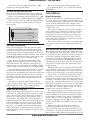
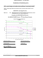
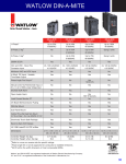
Solid-State Relay Derating Curve
98
99
Power
75 amps at 50 ºC
60
J3
Control
CF
common (RUI)
A1
L2
CD
T-/R- (RUI)
50
ST_ _ - _ _ A _ - _ _ _ _
Remote User Interface
(RUI)
L4
K2
CE
T+/R+ (RUI)
T2
T1
B5
- common (Digital I/O)
40
S2
30
S1
D6
R2
R1
D5
20
Power
98
Power
+ Digital Input40
6 oramps
Output 6at
50 ºC
+ Digital Input 5 or Output 5
99
Power
CC
common (Modbus RTU)
CA
T-/R- (Modbus RTU)
CB
T+/R+ (Modbus RTU)
ST_ _ - _ _ M _ - _ _ _ _
Modbus RTU on EIA-485
B5
- common (Digital I/O)
D6
+ Digital Input 6 or Output 6
D5
+ Digital Input 5 or Output 5
25 amps at 50 ºC
10
0
5
0
WARNING:
If high
L2 voltage
L2is
L2
appliedK2to a low-voltage
conK2
K2
+ T1
troller,T1irreversible
damage
T1
S3
will -occur.
S1
S1
S1
Process
Process
0 to 10VÎ (dc) 0 to 20 mA
0 to 50mVÎ (dc) (Input 1)
(Input 1)
Address
Selection
70
K3
common (Output 3)
Amps RMS
L4
80
N.O. (Output 3)
NOTE:
K3 Terminals
K3 L4 and
K3
N.C. (Output 3)
A1 onJ3the limitJ3connector
J3
contactor
(Coil 1)
are jumpered
at the factory
A1
A1
A1
N.O. (Output 4)
to complete
the
L4
L4 contactor
L4
+ T2 Additional
S2
circuit.
T2 switches
T2
- S2
S3
S2
may
be wired
in series
to the
S2
S3
S1
+
R2
R2
R2
terminals.
S1
OUT 2
Safe Operating Area
A1
STATUS
OUT 3
Limit
L3
Indicator
Lights
SSR
LIMIT
1234
J3
L3
Patent Pending
ON
K3
L3
2
EZ-ZONE™ ST
Integrated Control Loop
CAUTION: Always mount the
controller with the heat-sink
fins aligned vertically.
ST_ L - _ _ _ _ - _ _ _ _
all
See Quencharc note.
ST _ _ - A _ _ _ - _ _ _ _ (no contactor)
fuse
load
1
L3
SSR
OUT 2
SSR
STATUS
OUT 2
Output 1 Solid-State Relay with a Contactor
Warning:
Use Nationalfuse
Electric (NEC)
or other country-specific
Power
Supplyand safety
standard
wiring
when wiring and
ST_ _ practices
-__A_-____
Remote User Interface (RUI)
connecting this controller to
a power source and to electrical sensors or peripheral
devices. Failure to do so may
result in damage to equipment and property, and/or
injury or loss of life.
CB
D6
+ Digital Input 5 or Output 5
CE
D5
Ó
STATUS
Anderson-Bolds ~ 216-360-9800
R1
L2
K2
S2
T1
S3
S1
S1
R1
3-wire
RTD
(Input 1)
N.O. (Output 2)
common (Output 2)
10
Controller
L2
15
20
25
30
35
40
45
50
55
60
65
70
75
Ambient Temperatue (oC)
K2
T1
-
S1
+
R1
Thermocouple
(Input 1)
Quencharc Note:
Switching pilot duty inductive
loads (relay coils, solenoids,
etc.) with the mechanical
relay, solid state relay or
open collector output options
requires use of an R.C. suppressor.
Wat low EZ-ZONE ® ST
• 21 •
www.anderson-bolds.com
Chap ter 2 Install and Wire
Anderson-Bolds ~ 216-360-9800
Ó
Warning:
Use National Electric (NEC)
or other country-specific
standard wiring and safety
practices when wiring and
connecting this controller to
a power source and to electrical sensors or peripheral
devices. Failure to do so may
result in damage to equipment and property, and/or
injury or loss of life.
NOTE: To prevent ground
loops, isolation needs to be
maintained from input to output when using switched DC
or analog process outputs.
CAUTION: Always mount the
controller with the heat-sink
fins aligned vertically.
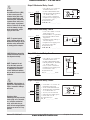
Output 2 Mechanical Relay, Form A
normally open
common
Slot B
L2
K2
Slot B
normally open
L2
common
K2
• 0.5 A at 20 to 264VÅ (ac) maximum resistive load
• 20 VA 120/240VÅ (ac) pilot duty
• opto-isolated, without contact
suppression
• maximum off state leakage of
105 microamperes
• Output does not supply power.
• Do not use on dc loads.
See Quencharc note.
ST (K, B, P, E) _ - _ _ _ _ - _ _ _ _
L2
K2
Slot A
normally open
L3
common
K3
J3
• 5 A at 240VÅ (ac) or 30VÎ (dc)
maximum resistive load
• 20 mA at 24V minimum load
• 125 VA pilot duty at 120/240VÅ
(ac), 25 VA at 24VÅ (ac)
• 100,000 cycles at rated load
• Output does not supply power.
• for use with ac or dc
See Quencharc note.
ST _ L - _ _ _ _ - _ _ _ _ (limit)
L3
normally open
K3
common
J3
normally closed
Output 4 Mechanical Relay, Form A
Slot A
WARNING: If high voltage is
applied to a low-voltage controller, irreversible damage
will occur.
common
normally open
Wat low EZ-ZONE ® ST
K2
Output 3 Mechanical Relay, Form C
NOTE: Terminals L4 and
A1 on the limit connector
are jumpered at the factory
to complete the contactor
circuit. Additional switches
may be wired in series to the
terminals.
Quencharc Note:
Switching pilot duty inductive
loads (relay coils, solenoids,
etc.) with the mechanical
relay, solid state relay or
open collector output options
requires use of an R.C. suppressor.
L2
Output 2 Solid-State Relay, Form A
normally closed
Ó
• 5 A at 240VÅ (ac) or 30VÎ (dc)
maximum resistive load
• 20 mV at 24V minimum load
• 125 VA pilot duty @ 120/240VÅ
(ac), 25 VA at 24VÅ (ac)
• 100,000 cycles at rated load
• Output does not supply power.
• for use with ac or dc
See Quencharc note.
ST (H, D, J, C) _ - _ _ _ _ - _ _ _ _
A1
L4
• 2 A at 240VÅ (ac) or 30VÎ (dc)
maximum resistive load
• 20 mV at 24V minimum load
• 125 VA pilot duty at 120/240VÅ
(ac), 25 VA at 24VÅ (ac)
• 100,000 cycles at rated load
• Output does not supply power.
• for use with ac or dc
See Quencharc note.
ST _ L - _ _ _ _ - _ _ _ _ (limit)
• 22 •
www.anderson-bolds.com
L4
A1
Chap ter 2 Install and Wire
Anderson-Bolds ~ 216-360-9800
Ó
Warning:
Use National Electric (NEC)
or other country-specific
standard wiring and safety
practices when wiring and
connecting this controller to
a power source and to electrical sensors or peripheral
devices. Failure to do so may
result in damage to equipment and property, and/or
injury or loss of life.
Digital Output 5 - 6
Slot C
98
99
CF
CD
CE
B5
common
D6
collector out
D5
collector out
• Internal supply provides a constant power
output of 750mW
• Maximum output sink
current per output is
1.5A (external class
2 or SELV supply required)
• Total sink current for
all outputs not to exceed 8A
• Do not connect outputs
in parallel
ST [B, C, D or E] _- _ _
_ _-_ _ _ _
common
B_
24 Vdc
D_
Quencharc Wiring Example
NOTE: To prevent ground
loops, isolation needs to be
maintained from input to output when using switched DC
or analog process outputs.
In this example the Quencharc
circuit (Watlow part# 0804-01470000) is used to protect ST internal circuitry from the counter
electromagnetic force from the inductive user load when de-engergized. It is recommended that this
or an equivalent Quencharc be
used when connecting inductive
loads to ST outputs.
User Load
L_
N
Quencharc
K_
CAUTION: Always mount the
controller with the heat-sink
fins aligned vertically.
NOTE: Terminals L4 and
A1 on the limit connector
are jumpered at the factory
to complete the contactor
circuit. Additional switches
may be wired in series to the
terminals.
Ó
WARNING: If high voltage is
applied to a low-voltage controller, irreversible damage
will occur.
Quencharc Note:
Switching pilot duty inductive
loads (relay coils, solenoids,
etc.) with the mechanical
relay, solid state relay or
open collector output options
requires use of an R.C. suppressor.
Wat low EZ-ZONE ® ST
• 23 •
www.anderson-bolds.com
Chap ter 2 Install and Wire
Anderson-Bolds ~ 216-360-9800
Ó
Warning:
Use National Electric (NEC)
or other country-specific
standard wiring and safety
practices when wiring and
connecting this controller to
a power source and to electrical sensors or peripheral
devices. Failure to do so may
result in damage to equipment and property, and/or
injury or loss of life.
NOTE: To prevent ground
loops, isolation needs to be
maintained from input to output when using switched DC
or analog process outputs.
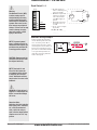
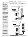
Standard Bus EIA-485 Communications
• Wire T-/R- to the A terminal of
the EIA-485 port.
• Wire T+/R+ to the B terminal of
the EIA-485 port.
• Wire common to the common
terminal of the EIA-485 port.
• Do not route network wires
with power wires. Connect network wires in daisy-chain fashion when connecting multiple
devices in a network.
Slot C
98
99
CF common
CD
CE
T-/RT+/R+
B5
D6
Modbus RTU or Standard Bus EIA-485 Communications
Slot C
98
99
CC common
CA
T-/RT+/R+
B5
NOTE: Terminals L4 and
A1 on the limit connector
are jumpered at the factory
to complete the contactor
circuit. Additional switches
may be wired in series to the
terminals.
* All models include Standard Bus
communications
D5
CB
CAUTION: Always mount the
controller with the heat-sink
fins aligned vertically.
• Do not connect more than 16
controllers on a network.
• maximum network length:
1,200 meters (4,000 feet)
• 1/8th unit load on EIA-485 bus
ST _ _ - _ _ * _ - _ _ _ _
D6
D5
• Wire T-/R- to the A terminal of
the EIA-485 port.
• Wire T+/R+ to the B terminal of
the EIA-485 port.
• Wire common to the common
terminal of the EIA-485 port.
• Do not route network wires
with power wires. Connect network wires in daisy-chain fashion when connecting multiple
devices in a network.
• A termination resistor may be
required. Place a 120 Ω resistor
across T+/R+ and T-/R- of last
controller on network.
• Only one protocol per port is
available at a time: either Modbus RTU or Standard Bus.
• Do not connect more than 16
controllers on a Standard Bus
network.
• Do not connect more than 247
controllers on a Modbus RTU
network.
• maximum network length:
1,200 meters (4,000 feet)
• 1/8th unit load on EIA-485 bus.
ST _ _ - _ _ M _ - _ _ _ _ (Modbus
RTU or EIA-485)
Modbus RTU or
Standard Bus EIA-485
Modbus-IDA
Terminal
EIA/TIA-485
Name
Watlow Terminal Label
Function
DO
A
CA or CD
T-/R-
D1
B
CB or CE
T+/R+
common
common
CC or CF
common
Ó
WARNING: If high voltage is
applied to a low-voltage controller, irreversible damage
will occur.
Note: Excessive writes to
EEPROM over Modbus can
cause premature EEPROM
failure. The EEPROM is rated
for 1,000,000 writes. See
"Saving Settings to Nonvolatile Memory" in Chapter 2,
Install and Wire.
Wat low EZ-ZONE ® ST
• 24 •
www.anderson-bolds.com
Chap ter 2 Install and Wire
Anderson-Bolds ~ 216-360-9800
Ó
T+/R+ and T-/R- of the last controller
Do not route network wires with pow- on a network.
er wires. Connect network wires in
Only one protocol per port is availdaisy-chain fashion when connecting
able at a time: either Modbus RTU or
multiple devices in a network.
Standard Bus.
Note:
A termination resistor may be reDo not route network wires with power
quired. Place a 120 Ω resistor across
wires.
A network using Watlow's Standard Bus and an RUI/Gateway.
Power
Supply
EZ-ZONE ST
ST_ _ - _ _ A _ -_ _ _ _
EZ-ZONE RM
fuse
98
99
-A
+B
NOTE: To prevent ground
loops, isolation needs to be
maintained from input to output when using switched DC
or analog process outputs.
CF
CD
B5
CE
D6
D5
Warning:
Use National Electric (NEC)
or other country-specific
standard wiring and safety
practices when wiring and
connecting this controller to
a power source and to electrical sensors or peripheral
devices. Failure to do so may
result in damage to equipment and property, and/or
injury or loss of life.
Wiring a Serial EIA-485 Network
power
power
common
98
99
power
com
-A
CD
+B
CE
CF
EZ-ZONE PM
B5
Slot C
D6
CZ
CX
CY
CE
99
CD
98
power
CAUTION: Always mount the
controller with the heat-sink
fins aligned vertically.
CF
D5
RUI/Gateway
EZKB-_ A _ _- _ _ _ _
98
power
common
-A
CD
+B
99
common
-A
+B
CF
CE
A network with all devices configured using Modbus RTU.
Power
Supply
EZ-ZONE ST
ST_ _ -_ _ M _ -_ _ _ _
EZ-ZONE RM
fuse
98
99
CA
CC
B5
CB
D6
-A
+B
power
power
common
98
99
EZ-ZONE PM
CC
CA
CB
Wat low EZ-ZONE ® ST
com
-A
+B
B5
Slot C
D6
CY
CZ
CX
CA
CB
98
D5
power
Note: Excessive writes to
EEPROM over Modbus can
cause premature EEPROM
failure. The EEPROM is rated
for 1,000,000 writes. See
"Saving Settings to Nonvolatile Memory" in Chapter 2,
Install and Wire.
power
power
99
WARNING: If high voltage is
applied to a low-voltage controller, irreversible damage
will occur.
D5
Ó
CC
NOTE: Terminals L4 and
A1 on the limit connector
are jumpered at the factory
to complete the contactor
circuit. Additional switches
may be wired in series to the
terminals.
PLC
power
power
common
-A
+B
• 25 •
www.anderson-bolds.com
common
-A
+B
Chap ter 2 Install and Wire
Anderson-Bolds ~ 216-360-9800
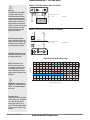
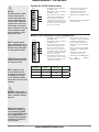
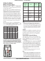
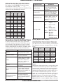
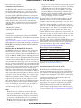
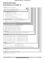
Setting the Address
Modbus Controller Address
The address of an EZ-ZONE® ST controller with the
Modbus option (ST _ _-_ _ M _-_ _ _ _) can be set to
ranges from 1 to 8 using the DIP switch and ranges
1 to 247 using software.
Set switch 4 to on to use Modbus communications.
Modbus™ RTU addresses from 1 to 247 can be programmed into the controller using Standard bus
communications. Only one controller can be connected to the network while changing the address
using communications. After the Modbus address is
changed, all four DIP switches must be turned on
(set to 8) and the controller restarted for the new address be become available on the Modbus network.
The Modbus addresses set by software will override
only address 8, but lower addresses set on the DIP
switch will override the software-assigned addresses.
As many as 247 controllers can be connected to a
network.
The Standard bus address of an EZ-ZONE ST controller with the Modbus™ RTU option (ST _ _-_ _ M
_-_ _ _ _) ranges from 1 to 8, because DIP switch 4 is
reserved for switching Modbus on or off.
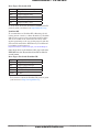
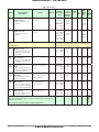
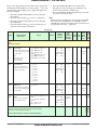
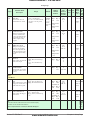
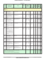
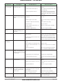
DIP Switch
Zone
1
2
3
**4
1
off
off
off
on
2
on
off
off
on
3
off
on
off
on
4
on
on
off
on
5
off
off
on
on
6
on
off
on
on
7
off
on
on
on
**8
on
on
on
on
**1 to 247
on
on
on
on
** Set switch 4 to on to use Modbus communications. Modbus addresses from 1 to 247 can be programmed into the
controller using Standard bus communications when switch
4 is off. After the Modbus address is changed, all four DIP
switches must be turned on (set to 8) for the new address to
become available on the Modbus network.
1
2
EZ-ZONE™ ST
Integrated Control Loop
Patent Pending
SSR
LIMIT
STATUS
OUT 3
Address
Selection
1234
K3
ON
L3
OUT 2
98
99
J3
Control
CF
A1
L2
CD
L4
K2
CE
T2
T1
B5
S2
S1
D6
R2
R1
D5
Wat low EZ-ZONE ® ST
Communications
Parameter
Name
Range
Modbus
(less 400,001
offset)
Data
Type
&
Read/
Write
Address (when
all four DIP
switches are set
to on)
* 1 to 247
Map 1 Map 2
313
2052
uint
RW
Baud
* 9,600 (188)
19,200 (189)
38,400 (190)
Map 1 Map 2
314
2054
uint
RWE
Parity
Even (191)
Odd (192)
* None (61)
Map 1 Map 2
315
2056
uint
RWE
Word Order
* Lowhigh (1331)
Highlow (1330)
Map 1 Map 2
- - - - 2058
uint
RWE
Non-Volatile
Save
(ST Firmware 2
and higher)
* Yes (106)
No (59)
Map 1 Map 2
317
2084
uint
RWE
* Defaults
Note:
Changing the Modbus parameters listed above
must be done over Modbus using ST firmware release 2.0 and earlier. For firmware release 3.0 and
above using either an RUI or EZ-ZONE Configurator software, navigate to the Setup Page and then
to the Com [Com] (RUI representation) menu to
change.
CAUTION:
Changes set over Modbus are immediate. Users will
not be able to communicate with the controller after
its address, parity or baud rate has been changed.
The master device will need to be re-configured to
the new settings.
Saving Settings to Nonvolatile Memory
When controller settings are entered using the optional RUI, changes are always saved to Non-volatile
Memory (EEPROM). If the controller loses power or
is switched off, its settings will be restored when it
starts again.
The EEPROM will wear out after about 1,000,000
writes, which would not be a problem with changes
made from the RUI. However, if the controller is receiving changing instructions from a PLC or a computer through a network connection, the EEPROM
could, over time, wear out. The Non-volatile Memory
Save parameter allows the user to save settings
made over the network to either volatile or nonvolatile memory.
By default, settings made through the network
are saved to non-volatile memory.
Note:
Changing Non-volatile Memory Save must be done
over the network using ST firmware release 2.0
and earlier. For firmware release 3.0 and above using either an RUI or EZ-ZONE Configurator software, navigate to the Setup Page and then to the
Com [Com] (RUI representation) menu to change.
• 26 •
www.anderson-bolds.com
Chapter 2 Install and Wire
Anderson-Bolds ~ 216-360-9800
Watlow Standard Bus Controller Address
The address of an EZ-ZONE ST controller using
Standard Bus exclusively (ST_ _ - _ _ A _ - _ _ _ _ )
ranges from 1 to 16, where up to 16 controllers can be
connected on the Standard Bus network.
DIP Switch
Zone
1
2
3
*4
1
off
off
off
off
2
on
off
off
off
3
off
on
off
off
4
on
on
off
off
5
off
off
on
off
6
on
off
on
off
7
off
on
on
off
8
on
on
on
off
Header Name
Definition
Profibus Index
Identifies unique parameters using Profibus DP
protocol (further explanation below).
Parameter ID
Identifies unique parameters used with other software such as, LabVIEW.
RUI/GTW Modbus
Identifies unique relative
Modbus (RTU or TCP) addresses when using the
Remote User Interface /
Gateway.
uint = Unsigned 16 bit
integer
dint = Signed 32-bit,
long
*9
off
off
off
on
*10
on
off
off
on
*11
off
on
off
on
*12
on
on
off
on
*13
off
off
on
on
RWES = Readable
*14
on
off
on
on
Writable
*15
off
on
on
on
EEPROM (saved)
*16
on
on
on
on
User Set (saved)
Conventions Used in the Menu Pages
To better understand the menu pages that follow
review the naming conventions used. When encountered throughout this document, the word "default"
implies as shipped from the factory. Each page (Operations, Setup, Profile and Factory) and their associated menus have identical headers defined below:
Header Name
Definition
Data Type R/W
string = ASCII (8 bits
per character)
float
= IEEE 754 32-bit
If Using Optional RUI (Display)
Visual information from the control is displayed to
the observer using a fairly standard 7 segment display. Due to the use of this technology, several characters displayed need some interpretation, see the list
below:
[1] = 1
[0] = 0
[i] = i
[r] = r
[2 = 2
[a] = A
[j] = J
[S] = S
Display
Visually displayed information from the control.
[3] = 3
[b] = b
[H] = K
[t] = t
[4] = 4
[c], [C] = c
[l] = L
[U] = u
Parameter Name
Describes the function of
the given parameter.
[5] = 5
[d] = d
[m] = M
[u] = v
[6] = 6
[e] = E
[n] = n
[w] = W
[7] = 7
[f] = F
[o] = o
[y] = y
Range
Defines options available
for this prompt, i.e., min/
max values (numerical),
yes/no, etc... (further explanation below).
[8] = 8
[g] = g
[p] = P
[2] = Z
[9] = 9
[h] = h
[q] = q
Default
Values as delivered from
the factory.
Modbus Relative Address
Identifies unique addresses when using either the
Modbus RTU or Modbus
TCP protocols (further explanation below).
CIP (Common Industrial Protocol)
Identifies unique parameters using either the
DeviceNet or EtherNet/IP
protocol (further explanation below).
Watlow EZ-ZONE ® ST
Range
Within this column notice that on occasion there will
be numbers found within parenthesis. This number
represents the enumerated value for that particular
selection. Range selections can be made simply by
writing the enumerated value of choice using any of
the available communications protocols. As an example, turn to the Setup Page and look at the Analog
Input [`Ai] menu and then the Sensor Type [Sen]
prompt (instance 1). To turn the sensor off using
Modbus simply write the value of 62 (off) to register
400043 (Map 1) or register 400369 (Map 2) and send
• 27 •
www.anderson-bolds.com
Chap ter 2 Install and Wire
Anderson-Bolds ~ 216-360-9800
that value to the control.
Communication Protocols
All EZ-ZONE ST controllers come standard with
the Standard Bus protocol. As a option it can also
be delivered with the Modbus protocol as well. The
Standard Bus protocol is used primarily for communications to other EZ-ZONE products to include the
RUI and EZ-ZONE Configurator software (free download from Watlow's web site (http://www.watlow.com).
Other protocols that can be used to communicate
with the ST are available when used in conjunction
with the optional Remote User Interface/Gateway
(RUIGTW).
- Modbus RTU 232/485
- EtherNet/IP, Modbus TCP
- DeviceNet
- Profibus DP
If interested in learning more about the RUI/GTW
download the RUI/Gateway User Manual by pointing
your browser to:
http://www.watlow.com/literature/pti_search.cfm?dltype=5
Once there move to the bottom of the page and enter
EZ-ZONE into the Keyword field and then click the
search button.
Modbus RTU & Modbus TCP Protocols
All Modbus registers are 16-bits and as displayed in
this manual are relative addresses (actual). Some
legacy software packages limit available Modbus registers to 40001 to 49999 (5 digits). Many applications
today require access to all available Modbus registers
which range from 400001 to 465536 (6 digits). Watlow
controls support 6 digit Modbus registers. For parameters listed as float notice that only one (low order) of
the two registers is listed, this is true throughout this
document. By default the low order word contains the
two low bytes of the 32-bit parameter. As an example,
look in the Operations Page for the Process Value.
Find the column identified in the header as Modbus
and notice that it lists register 19 (instance 1, Map 1)
and register 360 (instance 1, Map 2). Because this parameter is a float instance 1 Map 1 is actually represented by registers 19 (low order bytes) and 20 (high
order bytes), likewise, instance 1 Map 2 is actually
represented by registers 360 (low order bytes) and
361 (high order bytes). Because the Modbus specification does not dictate which register should be high
or low order Watlow provides the user the ability to
swap this order (Setup Page, [Com Menu) from the
default low/high [lohi] to high/low [hilo].
Note:
With the release of firmware revision 3.00 and
above new capabilities (phase angle control, user
programmable memory blocks, etc...) where introduced into this product line. With the introduction
of these new capabilities there was a repacking of
Modbus registers. Notice in the column identified
as Modbus the reference to Map 1 and Map 2 regWat low EZ-ZONE ® ST
isters for each of the various parameters. If the new
capabilities are to be used, be certain to select Map
2 Modbus registers. If the new functions of this
product line are not to be used, Map 1 (legacy ST
controls) Modbus registers will be sufficient. The
Modbus register mapping [map] can be changed
in the Setup Page under the [Com] Menu. This
setting will apply across the control.
It should also be noted that some of the cells in the
Modbus column as well as the RUI/GTW Modbus
column contain wording pertaining to an offset. Several parameters in the control contain more than one
instance; such as, profiles (4), alarms (2), analog inputs (2), etc... The Modbus register shown always represents instance one. Take for an example the Step
Type [styp] parameter found in the Profile Page.
Instance one, Map 1, is shown as address 500 and
+20 is identified as the offset to the next instance. If
there was a desire to read or write to instance 3 simply add 40 to 500 to find its address. In this case, the
instance 3 address for Step Type is 540.
The ST control, when equipped with Modbus has user
programmable memory blocks. To learn more about
this feature click on the link or turn to the Features
section and look for the section entitled "Modbus User Programmable Memory Blocks".
Data Types Used with Modbus
unsigned
= Unsigned 16 bit integer
signed
= Signed 16-bit
float
= Float, IEEE 754 32-bit
long
= 32 bit unsigned integer
sint
= Signed 8 bits , byte
To learn more about the Modbus protocol point your
browser to http://www.modbus.org.
Common Industrial Protocol (CIP)
DeviceNet & Ethernet/IP
Both DeviceNet and EtherNet/IP use open object
based programming tools and use the same addressing scheme. In the following menu pages notice the
column header identified as CIP. There you will find
the Class, Instance and Attribute in hexadecimal,
(decimal in parenthesis) which makes up the addressing for both protocols.
The ST control has a feature that allows for implicit
messaging when used in conjunction with an RUI/
GTW equipped with a DeviceNet or EtherNet/IP
card. To learn more about this feature click on the
link or turn to the Features section and look for the
section entitled "CIP - Communications Capabilities".
• 28 •
www.anderson-bolds.com
Chapter 2 Install and Wire
Anderson-Bolds ~ 216-360-9800
Data Types Used with CIP
uint
= Unsigned 16 bit integer
int
= Signed 16-bit
dint
= Signed 32-bits, long
real
= Float, IEEE 754 32-bit
string
= ASCII, 8 bits per character
sint
= Signed 8 bits , byte
To learn more about the DeviceNet and EtherNet/IP
protocol point your browser to http://www.odva.org.
Profibus DP
To accommodate for Profibus DP addressing the following menus contain a column identified as Profibus
Index. Data types used in conjunction with Profibus
DP can be found in the table below. For more information pertaining to the use of this protocol with the
ST control download the RUI/Gateway User Manual
by pointing your browser to:
http://www.watlow.com/literature/pti_search.cfm?dltype=5
Once there move to the bottom of the page and enter
EZ-ZONE into the Keyword field and then click the
search button.
Data Types Used with Profibus DP
Word
= Unsigned 16 bit
INT
= Signed 16-bit Integer
dint
= Signed 32-bit Integer
REAL
= Float, IEEE 754 32-bit
CHAR
= ASCII, 8 bits per character
BYTE
= 8 bits
To learn more about the Profibus DP protocol point
your browser to http://www.profibus.org
Watlow EZ-ZONE ® ST
• 29 •
www.anderson-bolds.com
Chap ter 2 Install and Wire
Anderson-Bolds ~ 216-360-9800
3
Chapter 3: Operations Pages
Control Module Operation Page Parameters
To go to the Operations Page from the Home Page,
press both the Up ¿ and Down ¯ keys for three seconds. [``Ai] will appear in the upper display and
[oPEr] will appear in the lower display.
• Press the Up ¿ or Down ¯ key to view available
menus. On the following pages top level menus
are identified with a yellow background color.
• Press the Advance Key ‰ to enter the menu of
choice.
• If a submenu exists (more than one instance),
[``Ai]
[oPEr] Analog Input Menu
[```1]
[``Ai] Analog Input 1
[`Ain] Process Value
[`i;Er] Error Status
[`i;Ca] Calibration Offset
[`dio]
[oPEr] Digital Input/Output Menu
[```1]
[`dio] Digital Input/Output 1
[`do;S] Output State
[`di;S] Event State
[LiM]
[oPEr] Limit Menu
[```1]
[LiM] Limit 1
[`LL;S] Low Set Point
[`Lh;S] High Set Point
[Mon]
[oPEr] Monitor Menu
[```1]
[Mon] Monitor 1
[C;MA] Control Mode Active
[`h;Pr] Heat Power
[`C;Pr] Cool Power
[`C;SP] Closed Loop Working Set
Point
[`Pu;A] Process Value Active
[Loop]
[oPEr] Loop Menu
[```1]
[Loop] Loop 1
[`C;M] Control Mode
[A;tSP] Autotune Set Point
[`AUt] Autotune Request
[`C;SP] Closed Loop Set Point
[`id;S] Idle Set Point
[`h;Pb] Heat Proportional Band
[`h;hy] Heat Hysteresis
[`C;Pb] Cool Proportional Band
Wat low EZ-ZONE ® ST
press the Up ¿ or Down ¯ key to select and then
press the Advance Key ‰ to enter.
• Press the Up ¿ or Down ¯ key to move through
available menu prompts.
• Press the Infinity Key ˆ to move backwards
through the levels: parameter to submenu; submenu to menu; menu to Home Page.
• Press and hold the Infinity Key ˆ for two seconds
to return to the Home Page.
[`C;hy] Cool Hysteresis
[``ti] Time Integral
[``td] Time Derivative
[``db] Dead Band
[`o;SP] Open Loop Set Point
[ALM]
[oPEr] Alarm Menu
[```1]
[ALM] Alarm 1
[`A;Lo] Low Set Point
[`A;hi] High Set Point
[CUrr]
[oPEr] Current Menu
[```1]
[CUrr] Current 1
[`C;hi] High Set Point
[`C;Lo] Low Set Point
[`CU;r] Read
[`C;Er] Error
[`h;Er] Heater Error
[P;StA]
[oPEr] Profile Status Menu
[```1]
[P;StA] Profile Status 1
[P;Str] Profile Start
[PACr] Action Request
[`StP] Active Step
[S;tyP] Active Step Type
[t;SP1] Target Set Point Loop 1
[P;SP1] Produced Set Point 1
[hour] Hours Remaining
[min] Minutes Remaining
[`sec] Seconds Remaining
[Ent1] Active Event Output 1
[Ent2] Active Event Output 2
[``JC] Jump Count Remaining
• 30 •
www.anderson-bolds.com
Chap ter 3 Operations Page
Anderson-Bolds ~ 216-360-9800
Operations Page
Display
Parameter Name
Description
Range
Default
Modbus
Relative Address
CIP
Pro DP
Class
Instance Index
Attribute
hex (dec)
Par
ID
Data
RUI/
Type
GTW
Mod- & Read/
Write
bus
[``Ai]
[oPEr]
Analog Input Menu
Inst. 1 float
360 R
[``Ain] Analog Input (1 to 2)
Process Value
[ Ain]
View the process value.
-1,999.000 to 9,999.000°F
or units
-1,128.000 to 5,537.000°C
Instance 1 0x68 (104)
1 to 2
Map 1 Map 2
1
---360
Instance 2
Map 1 Map 2
---450-
0
No Display
Analog Input (1 to 2)
Filtered Process Value
View the filtered process
value.
-1,999.000 to 9,999.000°F
or units
-1,128.000 to 5,537.000°C
Instance 1 0x68 (104)
1 to 2
Map 1 Map 2
0x16 (22)
---402
Instance 2
Map 1 Map 2
---492-
0
Analog Input (1)
Ambient Temperature
View ambient temperature.
-1,999.000 to 9,999.000°F
or units
-1,128.000 to 5,537.000°C
Instance 1 0x68 (104)
1
Map 1 Map 2
4
34
366
Instance 2
Map 1 Map 2
---492-
0
Analog Input (1 to 2)
Error Status
View the cause of the most
recent error. If the [Attn]
message is [Er;i1] or
[Er;i2], this parameter will
display the cause of the input error.
None
[nonE] None (61)
[OPEn] Open (65)
[Shrt] Shorted (127)
[`E;M] Measurement Error (149)
[E;CAL] Bad Calibration
Data (139)
[Er;Ab] Ambient Error (9)
[E;;Rtd] RTD Error (141)
[FAiL] Fail (32)
[NSrc] Not Sourced (146)
Instance 1 0x68 (104)
1 to 2
Map 1 Map 2
2
41
362
Instance 2
Map 1 Map 2
69
452
1
No Display
Analog Input (1)
Clear Latched Input Error
Clear latched input.
Clear (0)
No Change (255)
Instance 1 0x68 (104)
1
Map 1 Map 2
0x1D (29)
68
416
Instance 2
Map 1 Map 2
96
506
0
4029
Inst. 1 uint
416 W
[`i;Ca]
[ i.CA]
Analog Input (1 to 2)
-1,999.000 to 9,999.000°F 0.0
Calibration Offset
or units
Offset the input reading to
-1,110.555 to 5,555.000°C
compensate for lead wire resistance or other factors that
cause the input reading to
vary from the actual process
value.
Instance 1 0x68 (104)
1 to 2
Map 1 Map 2
0xC (12)
51
382
Instance 2
Map 1 Map 2
79
472
2
4012
Inst. 1 float
382 RWES
No Display
[`i;Er]
[ i.Er]
Note:
Some values will be rounded off to fit in the four-character display. Full values can be
read with other interfaces.
If there is only one instance of a menu, no submenus will appear.
Wat low EZ-ZONE ® ST
• 31 •
www.anderson-bolds.com
4001
Inst. 2
520
4022
Inst. 1 float
402 R
Inst. 2
562
4004
Inst. 1 float
402 R
Inst. 2
562
4002
Inst. 1 uint
362 R
Inst. 2
522
Inst. 2
542
R: Read
W: Write
E: EEPROM
S: User
Set
Chap ter 3 Operations Page
Anderson-Bolds ~ 216-360-9800
Operations Page
Parameter Name
Description
Display
Range
Default
Modbus
Relative Address
CIP
Pro DP
Class
Instance Index
Attribute
hex (dec)
Par
ID
Data
RUI/
Type
GTW
Mod- & Read/
Write
bus
`dio]
[oPEr]
Digital Input/Output Menu
[`do;S]
[ do.S]
[`ei;S]
[ Ei.S]
Digital Output (5 to 6)
Output State
View the state of this output.
[`off] Off (62)
[``on] On (63)
Digital Input (5 to 6)
Event Status
View this event input state.
[`off] Off (62)
[``on] On (63)
Inst. 5 uint
1012 R
Instance 1 0x6A (106)
5 to 6
Map 1 Map 2
7
175
1072
Instance 2
Map 1 Map 2
188
1102
90
Instance 1 0x6E (110)
1 to 2
Map 1 Map 2
5
32
1298
Instance 2
Map 1 Map 2
33
1318
140
Instance 1 0x70 (112)
1
Map 1 Map 2
3
275
724
38
12003 Inst. 1 float
684 RWES
Instance 1 0x70 (112)
1
Map 1 Map 2
4
277
726
39
12004 Inst. 1 float
686 RWES
6007
Inst. 6
1042
10005 Inst. 1 uint
1408 R
Inst. 2
1428
[LiM]
[oPEr]
Limit Menu
0.0°F or
units
Limit (1)
Low Set Point
Set the low process value
that will trigger the limit.
-1,999.000 to
9,999.000°F or units
-1,128.000 to
5,537.000°C
Limit (1)
High Set Point
Set the high process value
that will trigger the limit.
-1,999.000 to
9,999.000°F or units
-1,128.000 to
5,537.000°C
[l;st1]
[L.St1]
Limit (1)
Limit Status
Clear limit once limit condition is cleared.
Safe (1667)
Fail (32)
----
Instance 1
Map 1 Map 2
---744
No Display
Limit (1)
Output Value
Current state of limit output.
Off (62)
On (63)
----
No Display
Limit (1)
Limit State
Clear limit once limit condition is cleared.
Off (62)
None (61)
Limit High (51)
Limit Low (52)
Error (225)
No Display
Limit (1)
Limit Clear Request
Clear limit once limit condition is cleared.
Clear (0)
No Change (255)
[`LL;S]
[ LL.S]
[`Lh;S]
[ Lh.S]
-18.0°C
0.0°F or
units
-18.0°C
----
----
Inst. 1 uint
---- R
Instance 1 0x70 (112)
1
Map 1 Map 2
7
---732
----
----
Inst. 1 uint
---- R
----
Instance 1 0x70 (112)
1
Map 1 Map 2
6
280
730
----
12006 Inst. 1 uint
690 R
----
Instance 1 0x70 (112)
1
Map 1 Map 2
1
272
720
----
12001 Inst. 1 uint
680 W
Instance 1 0x97 (151)
1
Map 1 Map 2
2
222
1752
----
8002
----
[Mon]]
[oPEr]
Monitor Menu
[C;MA]
[C.MA]
Monitor (1)
Control Mode Active
View the current control
mode.
[`off] Off (62)
[AUto] Auto (10)
[MAn] Manual (54)
Note:
Some values will be rounded off to fit in the four-character display. Full values can be
read with other interfaces.
If there is only one instance of a menu, no submenus will appear.
Wat low EZ-ZONE ® ST
• 32 •
www.anderson-bolds.com
Inst. 1 uint
1880 R
R: Read
W: Write
E: EEPROM
S: User
Set
Chap ter 3 Operations Page
Anderson-Bolds ~ 216-360-9800
Operations Page
Parameter Name
Description
Display
Range
Default
Modbus
Relative Address
CIP
Pro DP
Class
Instance Index
Attribute
hex (dec)
Par
ID
Data
RUI/
Type
GTW
Mod- & Read/
Write
bus
[`h;Pr]
[ h.Pr]
Monitor (1)
Heat Power
View the current heat output level.
0.0 to 100.0%
0.0
Instance 1 0x97 (151)
1
Map 1 Map 2
0xD (13)
236
1774
----
8011
Inst. 1 float
1900 R
[`C;Pr]
[ C.Pr]
Monitor (1)
Cool Power
View the current cool output level.
-100.0 to 0.0%
0.0
Instance 1 0x97 (151)
1
Map 1 Map 2
0xE (14)
242
1776
----
8014
Inst. 1 float
1906 R
[`C;SP]
[ C.SP]
Monitor (1)
-1,999.000 to 9,999.000°F
Closed Loop Working Set
or units
Point
-1,128.000 to 5,537.000°C
View the set point currently
in effect.
Instance 1 0x97 (108)
1
Map 1 Map 2
0x1D
(29)
---- ----
----
8029
Inst. 1 float
1936 R
[`Pu;A]
[ Pv.A]
Monitor (1)
Process Value Active
View the active process
value.
-1,999.000 to 9,999.000°F
or units
-1,128.000 to 5,537.000°C
Instance 1 0x97 (108)
1
Map 1 Map 2
19
- - - - 0x1F (31)
----
8031
Inst. 1 float
1940 R
No Display
Monitor (1)
Set Point Active
Read the current active set
point.
-1,999.000 to 9,999.000°F
or units
-1,128.000 to 5,537.000°C
Instance 1 0x6B (107)
1
Map 1 Map 2
7
2172 2652
Instance 2
Map 1 Map 2
2252 2732
----
7018
Inst. 1 float
2172 R
[Loop]
[oPEr]
Loop Menu
[`C;M]
[ C.M]
Control Loop (1)
Control Mode
Select the method that this
loop will use to control.
[`off] Off (62)
[AUto] Auto (10)
[MAn] Manual (54)
Auto
Instance 1
Map 1 Map 2
221
1750
0x97
(151)
1
1
63
8001
Inst. 1 uint
1880 RWES
[A;tSP]
[A.tSP}
Control Loop (1)
Autotune Set Point
Set the set point that the
autotune will use, as a
percentage of the current
set point.
50.0 to 200.0%
90.0
Instance 1
Map 1 Map 2
260
1788
0x97
(151)
1
0x14 (20)
----
8025
Inst. 1 float
1928 RWES
[`AUt]
[ AUt]
Control Loop (1)
Autotune Request
Start an autotune. While the
autotune is active, the Home
Page will display [Attn]
[tUn1]. When the autotune
is complete, the message
will clear automatically.
[``no] No
[`YES] Yes
No
Instance 1
Map 1 Map 2
262
1790
0x97
(151)
1
0x15 (21)
64
8026
Inst. 1 uint
1930 RW
[`C;SP]
[ C.SP]
Control Loop (1)
Closed Loop Set Point
Set the set point that the
controller will automatically control to.
Low Set Point to High
Set Point (Setup Page)
75.0°F
or
units
24.0°C
Instance 1
Map 1 Map 2
21
1890
0x6B
(107)
1
1
49
7001
Inst. 1 float
1936 RWES
[`id;S]
[ id.S]
Control Loop (1)
Idle Set Point
Set a closed loop set point
that can be triggered by an
event state.
Low Set Point to High
Set Point (Setup Page)
75.0°F
or
units
24.0°C
Instance 1
Map 1 Map 2
207
1906
0x6B
(107)
1
9
50
7009
Inst. 1 float
- - - - RWES
Note:
Some values will be rounded off to fit in the four-character display. Full values can be
read with other interfaces.
If there is only one instance of a menu, no submenus will appear.
Wat low EZ-ZONE ® ST
• 33 •
www.anderson-bolds.com
R: Read
W: Write
E: EEPROM
S: User
Set
Chap ter 3 Operations Page
Anderson-Bolds ~ 216-360-9800
Operations Page
Display
Parameter Name
Description
Range
Default
Modbus
Relative Address
CIP
Pro DP
Class
Instance Index
Attribute
hex (dec)
Par
ID
Data
RUI/
Type
GTW
Mod- & Read/
Write
bus
[`h;Pb]
[ h.Pb]
Control Loop (1)
Heat Proportional Band
Set the PID proportional
band for the heat outputs.
0.001 to 9,999.000°F or
units
-1,110.555 to
5,555.000°C
25.0°F
or
units
14.0°C
Instance 1
Map 1 Map 2
232
1760
0x97
(151)
1
6
65
8009
Inst. 1 float
1896 RWES
[`h;hy]
[ h.hy]
Control Loop (1)
Heat Hysteresis
Set the control switching
hysteresis for on-off control.
This determines how far
into the “on” region the process value needs to move
before the output turns on.
0.001 to 9,999.000°F or
units
-1,110.555 to
5,555.000°C
3.0°F or
units
2.0°C
Instance 1
Map 1 Map 2
234
1770
0x97
(151)
1
0xB (11)
66
8010
Inst. 1 float
1898 RWES
[`C;Pb]
[ C.Pb]
Control Loop (1)
Cool Proportional Band
Set the PID proportional
band for the cool outputs.
0.001 to 9,999.000°F or
units
-1,110.555 to
5,555.000°C
25.0°F
or
units
14.0°C
Instance 1
Map 1 Map 2
238
1762
0x97
(151)
1
7
67
8012
Inst. 1 float
1902 RWES
[`C;hy]
[ C.hy]
Control Loop (1)
Cool Hysteresis
Set the control switching
hysteresis for on-off control.
This determines how far
into the “on” region the process value needs to move
before the output turns on.
0.001 to 9,999.000°F or
units
-1,110.555 to
5,555.000°C
3.0°F or
units
2.0°C
Instance 1
Map 1 Map 2
240
1772
0x97
(151)
1
0xC (12)
68
8013
Inst. 1 float
1904 RWES
[``ti]
[ ti]
Control Loop (1)
Time Integral
Set the PID integral for the
outputs.
0 to 9,999 seconds per
repeat
180.0
Instance 1
seconds Map 1 Map 2
per re226
1764
peat
0x97
(151)
1
8
69
8006
Inst. 1 float
1890 RWES
[``td]
[ td]
Control Loop (1)
Time Derivative
Set the PID derivative time
for the outputs.
0 to 9,999 seconds
0.0
Instance 1
seconds Map 1 Map 2
228
1766
0x97
(151)
1
9
70
8007
Inst. 1 float
1892 RWES
[``dB]
[ db]
Control Loop (1)
Dead Band
Set the offset to the proportional band. With a negative value, both heating and
cooling outputs are active
when the process value is
near the set point. A positive value keeps heating
and cooling outputs from
fighting each other.
-1,000.0 to 1,000.0°F or
units
-556 to 556°C
0.0
Instance 1
Map 1 Map 2
230
1768
0x97
(151)
1
0xA (10)
71
8008
Inst. 1 float
1894 RWES
[`o;SP]
[ o.SP]
Control Loop (1)
Open Loop Set Point
Set a fixed level of output
power when in manual
(open-loop) mode.
-100 to 100% (heat and
cool)
0 to 100% (heat only)
-100 to 0% (cool only)
0.0
Instance 1
Map 1 Map 2
23
1892
0x6B
(107)
1
2
51
7002
Inst. 1 float
- - - - RWES
No Display
Control Loop (1)
Loop Error
Open Loop detect deviation
has been exceeded.
None (61)
Open Loop (1274)
Reversed Sensor (1275)
----
Instance 1 0x6C (108)
1
Map 1 Map 2
- - - - 1798 0x30 (48)
----
8048
Inst. 1 uint
---- R
No Display
Control Loop (1)
Clear Loop Error
Current state of limit output.
Clear (129)
Ignore (204)
----
Instance 1 0x6C (108)
1
Map 1 Map 2
- - - - 1800 0x31 (49)
----
8049
Inst. 1 uint
---- W
Note:
Some values will be rounded off to fit in the four-character display. Full values can be
read with other interfaces.
If there is only one instance of a menu, no submenus will appear.
Wat low EZ-ZONE ® ST
• 34 •
www.anderson-bolds.com
R: Read
W: Write
E: EEPROM
S: User
Set
Chap ter 3 Operations Page
Anderson-Bolds ~ 216-360-9800
Operations Page
Parameter Name
Description
Display
Range
Default
Modbus
Relative Address
CIP
Pro DP
Class
Instance Index
Attribute
hex (dec)
Par
ID
Data
RUI/
Type
GTW
Mod- & Read/
Write
bus
[ALM]
[oPEr]
Alarm Menu
[`A;Lo]
[ A.Lo]
[`A;hi]
[ A.hi]
No Display
No Display
No Display
No Display
Alarm (1 to 2)
Low Set Point
If Alarm Type (Setup Page,
Alarm Menu) is set to:
process - set the process
value that will trigger a
low alarm.
deviation - set the span of
units from the closed loop
set point that will trigger
a low alarm.
-1,999.000 to
9,999.000°F or units
-1,128.000 to
5,537.000°C
32.0°F
or
units
0.0°C
Instance 1
Map 1 Map 2
99
1452
Instance 2
Map 1 Map 2
115
1512
0x6D
(109)
1 to 2
2
18
Alarm (1 to 2
High Set Point
If Alarm Type (Setup Page,
Alarm Menu) is set to:
process - set the process
value that will trigger a
high alarm.
deviation - set the span of
units from the closed loop
set point that will trigger
a high alarm.
-1,999.000 to
9,999.000°F or units
-1,128.000 to
5,537.000°C
300.0°F
or
units
150.0°C
Instance 1
Map 1 Map 2
97
1450
Instance 2
Map 1 Map 2
113
1510
0x6D
(109)
1 to 2
1
19
Alarm (1 to 2)
Alarm State
Read current state of alarm
Startup (88)
None (61)
Blocked (12)
Alarm low (8)
Alarm high (7)
Error (28)
None
Instance 1
Map 1 Map 2
29
1466
Instance 2
Map 1 Map 2
30
1526
0x6D
(109)
1 to 2
9
----
Alarm (1 to 2)
Alarm Clearable
Indicates if alarm can be
cleared.
[``no] No (59)
[`YES] Yes (106)
None
Instance 1
Map 1 Map 2
- - - - 1472
Instance 2
Map 1 Map 2
---1532
0x6D
(109)
1 to 2
0xC (12)
----
Alarm (1 to 2)
Alarm Clear Request
Write to this register to
clear an alarm
Clear (0)
No Change (255)
Instance 1
Map 1 Map 2
108
1474
Instance 2
Map 1 Map 2
124
1534
0x6D
(109)
1 to 2
0xD (13)
32
Alarm (1 to 2)
Alarm Silence Request
Write to this register to
silence an alarm
Clear (0)
No Change (255)
Instance 1
Map 1 Map 2
109
1476
Instance 2
Map 1 Map 2
125
1536
0x6D
(109)
1 to 2
0xE (14)
33
None
None
Note:
Some values will be rounded off to fit in the four-character display. Full values can be
read with other interfaces.
If there is only one instance of a menu, no submenus will appear.
Wat low EZ-ZONE ® ST
• 35 •
www.anderson-bolds.com
9002
Inst. 1 float
1482 RWES
Inst. 2
1532
9001
Inst. 1 float
1480 RWES
Inst. 2
1530
9009
Inst. 1 uint
1496 R
Inst. 2
1546
9012
Inst. 1 uint
1502 R
Inst. 2
1552
9013
Inst. 1 uint
1504 W
Inst. 2
1554
9014
Inst. 1 uint
1506 W
Inst. 2
1556
R: Read
W: Write
E: EEPROM
S: User
Set
Chap ter 3 Operations Page
Anderson-Bolds ~ 216-360-9800
Operations Page
Parameter Name
Description
Display
No Display
No Display
Range
Alarm (1 to 2)
Alarm Silenced
Indicates if alarm can be
silenced.
Yes (106)
No (59)
Alarm (1 to 2)
Alarm Latched
Indicates if alarm is
latched.
Yes (106)
No (59)
Default
----
----
[CUrr]]
[oPEr]]
Current Menu
[`C;hi]
[ C.hi]
Current (1)
High Set Point
Set the current value that
will trigger a high heater
error state.
-1,999.000 to 9,999.000
50.0
[`C;Lo]
[ C.Lo]
Current (1)
Low Set Point
Set the current value that
will trigger a low heater error state.
-1,999.000 to 9,999.000
0.0
[`CU;r]
[ CU.r]
Current (1)
Read
View the most recent current value monitored by the
current transformer.
-1,999.000 to 9,999.000
[`C;Er]
[ C.Er]
Current (1)
SSR Error
View the cause of the most
recent load fault.
[nonE] None (61)
[Shrt] Shorted (127)
[open] Open (65)
[`h;Er]
[ h.Er]
Current (1)
Heater Error
View the cause of the most
recent load fault monitored
by the current transformer.
No Display
Current (1)
Error Status
View the cause of the most
recent load fault
Modbus
Relative Address
0x6D
Instance 1
(109)
Map 1 Map 2
1 to 4
1500 1900
0x0B (11)
Instance 2
Map 1 Map 2
1550
1960
----
0x6D
Instance 1
(109)
Map 1 Map 2
1 to 4
1498 1898
0x0A (10)
Instance 2
Map 1 Map 2
1548
1958
----
Par
ID
9011
Data
RUI/
Type
GTW
Mod- & Read/
Write
bus
Inst. 1 uint
1500 R
Inst. 2
1550
9010
Inst. 1 uint
1498 R
Inst. 2
1548
Note:
To use the current sensing feature, Time Base (Setup Page, Output
Menu) must be set to 0.7 seconds or more.
- - - - 15008 Inst. 1 float
0x73
Instance 1
(115)
1134 RWES
Map 1 Map 2
1
286
1254
8
Instance 1
Map 1 Map 2
288
1256
0x73
(115)
1
9
----
15009 Inst. 1 float
1136 RWES
Instance 1
Map 1 Map 2
38
1240
0x73
(115)
1
1
----
15001 Inst. 1 float
---- R
None
Instance 1
Map 1 Map 2
40
1242
0x73
(115)
1
2
----
15002 Inst. 1 uint
1122 R
[nonE] None (61)
[high] High (37)
[Low] Low (53)
None
Instance 1
Map 1 Map 2
282
1244
0x73
(115)
1
3
----
15003 Inst. 1 uint
1124 R
[none] None (61)
[fail] Fail (32)
----
Instance 1
Map 1 Map 2
1160 1400
0x73
(115)
1
21
----
15021
Note:
Some values will be rounded off to fit in the four-character display. Full values can be
read with other interfaces.
If there is only one instance of a menu, no submenus will appear.
Wat low EZ-ZONE ® ST
CIP
Pro DP
Class
Instance Index
Attribute
hex (dec)
• 36 •
www.anderson-bolds.com
- - - - uint
R
R: Read
W: Write
E: EEPROM
S: User
Set
Chap ter 3 Operations Page
Anderson-Bolds ~ 216-360-9800
Operations Page
Display
Parameter Name
Description
[P;Sta]
[oPEr]
Profile Status Menu
[P;Str]
[P.Str]
Profile Status
Profile Start
Range
Default
Modbus
Relative Address
[nonE] None (61)
[ProF] Profile (77)
[PAUS] Pause (146)
[rESU] Resume (147)
[`End] Terminate (148)
[step] Step (89)
None
Profile Status
Active Step
View the currently running
step.
1 to 40
0 (none)
Profile Status
Active Step Type
View the currently running
step type.
[UStP] Unused Step
(50)
[``ti] Time (143)
[rAtE] Rate (81)
[SoAH] Soak (87)
[w;e] Wait for Event
(144)
[w;pr] Wait for Process(209)
[CloC] Wait for Time
(1543)
[``JL] Jump Loop (116)
[`End] End (27)
----
[t;SP1]
[tg.SP]
Profile Status
*Target Set Point Loop 1
View or change the target
set point of the current
step.
-1,999.000 to
9,999.000°F or units
-1,128.000 to
5,537.000°C
[P;SP1]
[P.SP1]
Profile Status
Produced Set Point 1
Display the current set
point, even if the profile is
ramping.
[hour]
[hour]
[min]
[Min]
[`StP]
[ StP]
[S;typ]
[S.typ]
Par
ID
Data
RUI/
Type
GTW
Mod- & Read/
Write
bus
* Some parameters in the Profile Status Menu can be changed for the currently running profile,
but should only be changed by knowledgeable personnel and with caution. Changing parameters via the Profile Status Menu will not change the stored profile but will have an immediate
impact on the profile that is running.
Changes made to profile parameters in the Profiling Pages will be saved and will also have an
immediate impact on the running profile.
204
22001 Inst. 1 uint
0x7A
1 to 40
1
Instance 1
(122)
2898 RWE
Map 1 Map 2
292
[P;ACr]
[PACr]
CIP
Pro DP
Class
Instance Index
Attribute
hex (dec)
3800
1
1
Offset
+ 80
22011 Inst. 1 uint
2920 RW
Instance 1
Map 1 Map 2
306
3820
0x7A
(122)
1
0xB (11)
205
Instance 1
Map 1 Map 2
296
3806
0x7A
(122)
1
4
----
Instance 1
Map 1 Map 2
- - - - 3824
0x7A
(122)
1
0xD (13)
----
0.0°F
or
units
-18.0°C
Instance 1
Map 1 Map 2
- - - - 3822
0x7A
(122)
1
0xC (12)
----
22012
-1,999.000 to
9,999.000°F or units
-1,128.000 to
5,537.000°C
0.0°F
or
units
-18.0°C
Instance 1
Map 1 Map 2
297
3808
----
----
22005 Inst. 1 float
2908 R
Profile Status
Hours Remaining
0 to 99
0.0
Instance 1
Map 1 Map 2
---- ----
----
----
22078
---- ----
Profile Status
Minutes Remaining
0 to 59
0.0
Instance 1
Map 1 Map 2
---- ----
----
----
22077
---- ----
Profile Status
Action Request
Note:
Some values will be rounded off to fit in the four-character display. Full values can be
read with other interfaces.
If there is only one instance of a menu, no submenus will appear.
Wat low EZ-ZONE ® ST
• 37 •
www.anderson-bolds.com
Offset
+ 80
22004 Inst. 1 uint
2906 R
Offset
+ 80
22013 Inst. 1 uint
2924 R
Offset
+ 80
- - - - uint
RW
Offset
+ 80
R: Read
W: Write
E: EEPROM
S: User
Set
Chap ter 3 Operations Page
Anderson-Bolds ~ 216-360-9800
Operations Page
Display
Parameter Name
Description
Range
Default
Modbus
Relative Address
CIP
Pro DP
Class
Instance Index
Attribute
hex (dec)
Par
ID
Data
RUI/
Type
GTW
Mod- & Read/
Write
bus
---- ----
[sec]
[ Sec]
Profile Status
Seconds Remaining
0 to 59
0.0
Instance 1
Map 1 Map 2
---- ----
----
----
22076
No Display
Profile Status
Profile State
Off (62)
Running (149)
Pause (146)
Off
Instance 1
Map 1 Map 2
294
3802
0x7A
(122)
1
2
----
22002 Inst. 1 init
2902 R
0 to 4
0
Instance 1
Map 1 Map 2
295
3804
0x7A
(122)
1
2
----
Instance 1
Map 1 Map 2
303
3816
0x7A
(122)
1
9
----
Instance 1
Map 1 Map 2
- - - - 3826
0x7A
(122)
1
0xE (14)
----
Instance 1
Map 1 Map 2
- - - - 3828
0x7A
(122)
1
0xF (15)
----
Instance 1
Map 1 Map 2
305
3818
0x7A
(122)
1
0xA (10)
----
No Display
No Display
[Ent1]
[Ent1]
[Ent2]
[Ent2]
[``JC]
[ JC]
Profile Status
Active File
Profile Status
Total Step Time Remaining
In seconds
0.0 to 9999.000
Profile Status
*Active Event Output 1
View or change the event
output states.
[`off] Off (62)
[``on] On (63)
Profile Status
*Active Event Output 2
View or change the event
output states.
[`off] Off (62)
[``on] On (63)
Profile Status
Jump Count Remaining
View the jump counts
remaining for the current loop. In a profile with
nested loops, this may not
indicate the actual jump
counts remaining.
0 to 9,999
0.0
Off
Off
0
Note:
Some values will be rounded off to fit in the four-character display. Full values can be
read with other interfaces.
If there is only one instance of a menu, no submenus will appear.
Wat low EZ-ZONE ® ST
• 38 •
www.anderson-bolds.com
Offset
+ 80
22003 Inst. 1 init
2904 R
Offset
+ 80
22009 Inst. 1 float
2916 RW
Offset
+ 80
22014 Inst. 1 usint
2926 RW
Offset
+ 80
22015 Inst. 1 usint
2928 RW
Offset
+ 80
22010 Inst. 1 uint
2918 R
Offset
+ 80
R: Read
W: Write
E: EEPROM
S: User
Set
Chap ter 3 Operations Page
Anderson-Bolds ~ 216-360-9800
4
Chapter 4: Setup Pages
Control Module Setup Page Parameters
To go to the Setup Page from the
Home Page, press both the Up ¿
and Down ¯ keys for six seconds.
[``Ai] will appear in the upper
display and [`Set] will appear in
the lower display.
• Press the Up ¿ or Down ¯
key to view available menus.
On the following pages top
level menus are identified with
[``Ai]
[`Set] Analog Input Menu
[```1]
[``Ai] Analog Input 1 (to 2)
[`SEn] Sensor Type
[`Lin] Linearization
[`rt;L] RTD Leads
[Unit] Units
[`S;Lo] Scale Low
[`S;hi] Scale High
[`r;Lo] Range Low
[`r;hi] Range High
[`P;EE] Process Error Enable
[`P;EL] Process Error Low
[`FiL] Filter
[`i;er] Error Latching
[`dEC] Display Precision
[`s;ba] Sensor Backup
a yellow background color.
• Press the Advance Key ‰ to
enter the menu of choice.
• If a submenu exists (more than
one instance), press the Up ¿
or Down ¯ key to select and
then press the Advance Key ‰
to enter.
• Press the Up ¿ or Down ¯
key to move through available
[t;tUn] Tru-Tune+® Enable
[t;bnd] Tru-Tune+ Band
[`t;gn] Gain
[t;Agr] Autotune Aggressiveness
[`P;dl] Peltier Delay
[`UFA] User Failure Action
[FAiL] Input Error Failure
[MAn] Manual Power
[`L;dE] Open Loop Detect Enable
[`L;dt] Open Loop Detect Time
[`L;dd] Open Loop Detect Deviation
[``rp] Ramp Action
[`r;SC] Ramp Scale
[`r;rt] Ramp Rate
[`L;SP] Set Point Closed Limit Low
[`h;SP] Set Point Closed Limit High
[SP;Lo] Set Point Open Limit Low
[SP;hi] Set Point Open Limit High
[`dio]
[`Set] Digital Input/Output Menu
[```1]
[`dio] Digital Input/Output 5 (to 6)
[`dir] Direction
[``Fn] Output Function
[``Fi] Function Instance
[`o;Ct] Control
[`o;tb] Time Base
[`LEu] Active Level
[``Fn] Action Function
[``Fi] Function Instance
[otpt]
[`Set] Output Menu
[```1]
[otpt] Output 1 (to 4)
[``Fn] Output (2 to 4) Function
[``Fi] Function Instance
[`o;Ct] Control
[`o;tb] Time Base
[`o;Lo] Low Power Scale
[`o;hi] High Power Scale
[``Fn] Output (1) Function
[ss;ti] Soft Start Time
[LiM]
[`Set] Limit Menu
[```1]
[LiM] Limit 1
[`L;SD] Sides
[`L;hy] Hysteresis
[SP;Lh] Set Point Limit High
[SP;LL] Set Point Limit Low
[`L;it] Limit Integrate
[ALM]
[`Set] Alarm Menu
[```1]
[ALM] Alarm 1 (to 2)
[`A;ty] Type
[`sr;a] Source
[`is;a] Instance
[`A;hy] Hysteresis
[`a;Lg] Logic
[`A;SD] Sides
[`a;LA] Latching
[`A;bL] Blocking
[`a;Si] Silencing
[A;dsp] Display
[`A;dL] Delay
[Loop]
[`Set] Control Loop Menu
[```1]
[Loop] Control Loop 1
[`h;Ag] Heat Algorithm
[`C;Ag] Cool Algorithm
Watlow EZ-ZONE ® ST
• 39 •
www.anderson-bolds.com
menu prompts.
• Press the Infinity Key ˆ to
move backwards through the
levels: parameter to submenu;
submenu to menu; menu to
Home Page.
• Press and hold the Infinity
Key ˆ for two seconds to return to the Home Page.
[CUrr]
[`Set] Current Menu
[```1]
[CUrr] Current 1 (to 4)
[`C;Sd] Sides
[`C;Ur] Read Enable
[`C;le] Limit Enable
[`C;dt] Detection Threshold
[C;ofs] Heater Current Offset
[`fUn]
[`Set] Function Key Menu
[```1] to [```2]
[`fUn] Function Key
[``Fn] Event Function
[``fi] Function Instance
[gLbL]
[`Set] Global Menu
[```1]
[gLbl] Global
[`C_F] Display Units
[AC;LF] AC Line Frequency
[p;typ] Profile Start Type
[`gse] Guaranteed Soak Enable
[gsd1] Guaranteed Soak Deviation
[d;prs] Display Pairs
[USr;S] User Settings Save
[USr;r] User Settings Restore
[COM]
[`Set] Communications Menu
[```1]
[COM] Communications
[ad;m] Modbus Address
[bAUd] Baud Rate
[`PAr] Parity
[M;hL] Modbus Word Order
[`C_F] Display Units
[map] Data Map
[`nu;s] Non-Volatile Save
Chap ter 4 Setup Page
Anderson-Bolds ~ 216-360-9800
To go to the Setup Page from the Home Page, press both
the Up ¿ and Down ¯ keys for six seconds. [``Ai] will
appear in the upper display and [`Set] will appear in
the lower display.
• Press the Up ¿ or Down ¯ key to move through
the menus.
• Press the Advance Key ‰ to move to a submenu.
• Press the Up ¿ or Down ¯ key to move through
the submenus.
• Press the Advance Key ‰ to move through the parameters of the menu or submenu.
• Press the Infinity Key ˆ to move backwards
through the levels: parameter to submenu; submenu to menu; menu to Home Page.
• Press and hold the Infinity Key ˆ for two seconds
to return to the Home Page.
Note:
Avoid continuous writes within loops. Excessive writes to EEPROM will cause premature EEPROM failure. The EEPROM is rated for 1,000,000 writes. Navigate to Setup Page under the CoM menu and set prompt Non-volatile Save [`nU;S] to No.
Setup Page
Display
Parameter Name
Description
Range
Default
Modbus
Relative
Address
CIP
Class
Pro DP
Instance
Index
Attribute
hex (dec)
Par
ID
Data
RUI/
Type
GTW
&
ModRead/
bus
Write
[``Ai]
[`Set]
Analog Input Menu
[`Sen] Analog Input (1 to 2)
Sensor Type
[ SEn]
Set the analog sensor type
to match the device wired
to this input.
Note:
There is no open-
sensor detection for process inputs.
[`Lin] Analog Input (1 to 2)
Linearization
[ Lin]
Set the linearization to
match the thermocouple
wired to this input.
[`Rt;L]
[ rt.L]
[Unit]
[Unit]
[`oFF] Off (62)
[``tC] Thermocouple (95)
[`mu] Millivolts (56)
[uolT] Volts dc (104)
[`MA] Milliamps dc (112)
[r0;1H] RTD 100 Ω (113)
[r1;0H] RTD 1,000 Ω (114)
[```J] J (46)
[```F] F (30)
[```E] E (26)
[```d] D (23)
[```C] C (15)
[```b] B (11)
[```t] T (93)
[```S] S (84)
[```r] R (80)
[```n] N (58)
[```H] K (48)
Analog Input (1 to 2)
[```2] 2 (1)
RTD Leads
[```3] 3 (2)
Set to match the number
of leads on the RTD wired
to this input.
Analog Input (1 to 2)
Units
Set the type of units the
sensor will measure.
J
2
[`A;tP] Absolute Temperature Process
(1540)
[``rh] Relative Humidity
(1538)
[`Pro] Process (75)
[PWr] Power (73)
Instance 1 0x68 (104)
1 to 2
Map 1 Map 2
5
42
368
Instance 2
Map 1 Map 2
70
458
3
Instance 1 0x68 (104)
1 to 2
Map 1 Map 2
6
43
370
Instance 2
Map 1 Map 2
71
460
4
Instance 1 0x68 (104)
1 to 2
Map 1 Map 2
7
44
372
Instance 2
Map 1 Map 2
72
462
----
Instance 1 0x68 (104)
1 to 2
Map 1 Map 2
0x2A (42)
---442
Instance 2
Map 1 Map 2
- - - - 532
5
Note:
Some values will be rounded off to fit in the four-character display.
Full values can be read with other interfaces.
If there is only one instance of a menu, no submenus will appear.
Watlow EZ-ZONE ® ST
• 40 •
www.anderson-bolds.com
4005 Inst. 1 uint
368 RWES
Inst. 2
528
4006 Inst. 1 uint
370 RWES
Inst. 2
530
4007 Inst. 1 uint
372 RWES
Inst. 2
532
4042
- - - - uint
RWES
R: Read
W: Write
E: EEPROM
S: User
Set
Chap ter 4 Setup Page
Anderson-Bolds ~ 216-360-9800
Setup Page
Display
[`S;Lo]
[ S.Lo]
[`S;hi]
[ S.hi]
[`r;Lo]
[ r.Lo]
Parameter Name
Description
Analog Input (1 to 2)
Scale Low
Set the low scale for process inputs. This value,
in millivolts, volts or milliamps, will correspond to
the Range Low output of
this function block.
Range
-100.0 to 1,000.0
-100.0 to 1,000.0
Analog Input (1 to 2)
Scale High
Set the high scale for
process inputs. This value,
in millivolts, volts or milliamps, will correspond to
the Range High output of
this function block.
Analog Input (1 to 2)
Range Low
Set the low range for this
function block's output.
-1,999.000 to 9,999.000
Default
0.0
20.0
0.0
Modbus
Relative
Address
CIP
Class
Pro DP
Instance
Index
Attribute
hex (dec)
Instance 1 0x68 (104)
1 to 2
Map 1 Map 2
0xF (15)
57
388
Instance 2
Map 1 Map 2
85
478
6
Instance 1 0x68 (104)
1 to 2
Map 1 Map 2
0x10 (16)
59
390
Instance 2
Map 1 Map 2
87
480
7
Instance 1 0x68 (104)
1 to 2
Map 1 Map 2
0x11 (17)
61
392
Instance 2
Map 1 Map 2
89
482
8
Instance 1 0x68 (104)
1 to 2
Map 1 Map 2
0x12 (18)
63
394
Instance 2
Map 1 Map 2
91
484
9
Par
ID
Data
RUI/
Type
GTW
&
ModRead/
bus
Write
4015 Inst. 1 float
388 RWES
Inst. 2
548
4016 Inst. 1 float
390 RWES
Inst. 2
550
4017 Inst. 1 float
392 RWES
Inst. 2
552
4018 Inst. 1 float
394 RWES
-1,999.000 to 9,999.000
Analog Input (1 to 2)
Range High
Set the high range for this
function block's output.
9,999
[`P;EE]
[ P.EE]
Analog Input (1 to 2)
Process Error Enable
Turn the Process Error
Low feature on or off.
[`off] Off (62)
[Low] Low (53)
Off
Instance 1 0x68 (104)
1 to 2
Map 1 Map 2
0x1E (30)
---418
Instance 2
Map 1 Map 2
---508
10
4030
- - - - uint
RWES
[`P;EL]
[ P.EL]
Analog Input (1 to 2)
Process Error Low
If the process value drops
below this value, it will
trigger an input error.
-100.0 to 1,000.0
0.0
Instance 1 0x68 (104)
1 to 2
Map 1 Map 2
0x1F (31)
---420
Instance 2
Map 1 Map 2
---510
11
4031
- - - - float
RWES
[`FiL]
[ FiL]
0.0 to 60.0 seconds
Analog Input (1 to 2)
Filter
Filtering smooths out the
process signal to both the
display and the input.
Increase the time to increase filtering.
0.5
Instance 1 0x68 (104)
1 to 2
Map 1 Map 2
0xE (14)
55
386
Instance 2
Map 1 Map 2
83
476
12
4014 Inst. 1 float
386 RWES
[`r;hi]
[ r.hi]
Note:
Some values will be rounded off to fit in the four-character display.
Full values can be read with other interfaces.
If there is only one instance of a menu, no submenus will appear.
Watlow EZ-ZONE ® ST
• 41 •
www.anderson-bolds.com
Inst. 2
554
Inst. 2
546
R: Read
W: Write
E: EEPROM
S: User
Set
Chap ter 4 Setup Page
Anderson-Bolds ~ 216-360-9800
Setup Page
Display
[`i;Er]
[ i.Er]
[`dEC]
[ dEC]
[`s;ba]
[ S.bA]
Parameter Name
Description
Range
Default
Analog Input (1 to 2)
[`off] Off (62)
Error Latching
[``on] On (63)
Turn input error latching
on or off. If latching is on,
errors must be manually
cleared.
Off
Analog Input (1 to 2)
Display Precision
Set the precision of the
displayed value.
[```0] Whole (105)
[``0;0] Tenths (94)
[`0;00] Hundredths (40)
[0;000] Thousandths (96)
Whole
Analog Input (1 to 2)
Sensor Backup
Enable sensor backup.
[`off] Off (62)
[``on] On (63)
Off
Modbus
Relative
Address
CIP
Class
Pro DP
Instance
Index
Attribute
hex (dec)
Instance 1 0x68 (104)
1 to 2
Map 1 Map 2
0x1C (28)
67
414
Instance 2
Map 1 Map 2
95
504
----
Instance 1 0x68 (104)
1 to 2
Map 1 Map 2
0x14 (20)
---398
Instance 2
Map 1 Map 2
---488
----
Instance 1 0x68 (104)
1 to 2
Map 1 Map 2
0x1A (26)
65
410
Instance 2
Map 1 Map 2
93
500
----
Par
ID
Data
RUI/
Type
GTW
&
ModRead/
bus
Write
4028 Inst. 1 uint
414 RWES
Inst. 2
574
4020 Inst. 1 uint
398 RWES
Inst. 2
558
4026 Inst. 1 uint
410 RWES
Inst. 2
570
[`dio]
[`Set]
Digital Input/Output Menu
[`dir]
[ dir]
[``Fn]
[ Fn]
[``Fi]
[ Fi]
[`o;Ct]
[ o.Ct]
Digital Input/Output (5
Output
[OtPt] Output (68)
or 6)
[``in] Input Voltage (193)
Direction
[iCon] Input Dry Contact (44)
Set this function to operate as an input or output.
Instance 5
Map 1 Map 2
169
1060
Instance 6
Map 1 Map 2
182
1090
0x6A
(106)
5 to 6
1
82
Digital Output (5 or 6)
Function
Select what function will
drive this output.
[`oFF] Off (62)
[heat] Heat, Control Loop
(36)
[cool] Cool, Control Loop (20)
[Ent;A] Profile Event Out A
(233)
[Ent;b] Profile Event Out B
(234)
[LiM] Limit (126)
[ALM] Alarm (6)
Instance 5
Map 1 Map 2
173
1068
Instance 6
Map 1 Map 2
186
1098
0x 6A
(106)
5 to 6
5
83
Digital Output (5 or 6)
Function Instance
Set the instance of the
function selected above.
1 or 2
Instance 5
Map 1 Map 2
174
1070
Instance 6
Map 1 Map 2
187
1100
0x6A
(106)
5 to 6
6
84
Digital Output (5 or 6)
Control
Set the output control
type. This parameter
is only used with PID
control, but can be set
anytime.
[`Ftb] Fixed Time Base (34)
[`utb] Variable Time Base
(103)
Instance 5
Map 1 Map 2
170
1062
Instance 6
Map 1 Map 2
183
1092
0x6A
(106)
5 to 6
2
85
1
Fixed
Time
Base
Note:
Some values will be rounded off to fit in the four-character display.
Full values can be read with other interfaces.
If there is only one instance of a menu, no submenus will appear.
Watlow EZ-ZONE ® ST
• 42 •
www.anderson-bolds.com
6001 Inst. 5 uint
1000 RWES
Inst. 6
1030
6005 Inst. 5 uint
1008 RWES
Inst. 6
1068
6006 Inst. 5 uint
1010 RWES
Inst. 6
1040
6002 Inst. 5 uint
1002 RWES
Inst. 6
1032
R: Read
W: Write
E: EEPROM
S: User
Set
Chap ter 4 Setup Page
Anderson-Bolds ~ 216-360-9800
Setup Page
Display
[`o;tb]
[ o.tb]
[`o;Lo]
[ o.Lo]
[`o;hi]
[ o.hi]
[`leu]
[ LEv]
[``Fn]
[ Fn]
Parameter Name
Description
Range
Digital Output (5 or 6)
Time Base
Set the time base for
fixed-time-base control.
0.1 for Fast and Bi-Directional
outputs, 5.0 for Slow outputs] to 60
Digital Output (5 or 6)
Low Power Scale
The power output will
never be less than the
value specified and will
represent the value at
which output scaling
begins.
0.0 to 100.0
Digital Output (5 or 6)
High Power Scale
The power output will
never be greater than
the value specified and
will represent the value
at which output scaling
stops.
0.0 to 100.0
Digital Input (5 or 6)
Level
Select which action will
be interpreted as a true
state.
[high] High (37)
[LoW] Low (53)
Digital Input (5 or 6)
[none] None (61)
Action Function
[lmr] Limit Reset (82)
Select the function that
[P;StS] Profile Start/Stop
will be triggered by a true (208)
state.
[ProF] Start Profile (196)
[P;hoL] Profile Hold/Resume
(207)
[P;diS] Profile Disable (206)
[`t;dA] TRU-TUNE+™ Disable (219)
[`off] Switch Loop Off (62)
[MAn] Manual (54)
[tUnE] Tune (98)
[idLE] Idle Set Point (107)
[`F;AL] Force Alarm to Occur
(218)
[`AoF] Control Loops Off and
Alarms to Non-alarm State
(220)
[`SiL] Silence Alarms (108)
[ALM] Alarm (6)
[USr;r] User Settings Restore
(227)
Default
0.0
100.0
High
Modbus
Relative
Address
Instance 5
Map 1 Map 2
171
1064
Instance 6
Map 1 Map 2
184
1094
0x6A
(106)
5 to 6
3
86
Instance 5
Map 1 Map 2
178
1076
Instance 6
Map 1 Map 2
191
1106
0x6A
(106)
5 to 6
9
87
Instance 5
Map 1 Map 2
180
1078
Instance 6
Map 1 Map 2
193
1108
0x6A
(106)
5 to 6
0xA (10)
88
Instance 5
Map 1 Map 2
264
1290
Instance 6
Map 1 Map 2
268
1310
0x6E
(110)
5 to 6
1
137
Instance 5
Map 1 Map 2
266
1294
Instance 6
Map 1 Map 2
270
1314
0x6E
(110)
5 to 6
3
138
Note:
Some values will be rounded off to fit in the four-character display.
Full values can be read with other interfaces.
If there is only one instance of a menu, no submenus will appear.
Watlow EZ-ZONE ® ST
CIP
Class
Pro DP
Instance
Index
Attribute
hex (dec)
• 43 •
www.anderson-bolds.com
Par
ID
Data
RUI/
Type
GTW
&
ModRead/
bus
Write
6003 Inst. 5 float
1004 RWES
Inst. 6
1034
6009 Inst. 5 float
1016 RWES
Inst. 6
1046
6010 Inst. 5 float
1018 RWES
Inst. 6
1048
10001 Inst. 5 uint
1400 RW
Inst. 6
1420
10003 Inst. 5 uint
1404 RWES
Inst. 6
1424
R: Read
W: Write
E: EEPROM
S: User
Set
Chap ter 4 Setup Page
Anderson-Bolds ~ 216-360-9800
Setup Page
Parameter Name
Description
Display
[``Fi]
[ Fi]
Range
Digital Input (5)
0 to 4
Function Instance
Select which instance of
the Event Function that
will be triggered by a true
state.
Default
0
Modbus
Relative
Address
Instance 1
Map 1 Map 2
267
1296
Instance 2
Map 1 Map 2
271
1316
CIP
Class
Pro DP
Instance
Index
Attribute
hex (dec)
0x6E
(110)
1
4
139
Par
ID
Data
RUI/
Type
GTW
&
ModRead/
bus
Write
10004 Inst. 5 uint
1406 RWES
Inst. 6
1426
[Lim]
[`Set]
Limit Menu
[`L;Sd]
[ L.Sd]
Limit (1)
[both] Both (13)
Sides
[high] High (37)
Select which side or sides [LoW] Low (53)
of the process value will
be monitored.
Both
Instance 1 0x70 (112)
1
Map 1 Map 2
5
279
728
40
12005 Inst. 1 uint
688 RWES
[`L;hy]
[ L.hy]
Limit (1)
0.001 to 9,999.000°F or units
Hysteresis
0.001 to 5,555.000°C
Set the hysteresis for
the limit function. This
determines how far into
the safe range the process
value must move before
the limit can be cleared.
3.0°F or
units
2.0°C
Instance 1 0x70 (112)
1
Map 1 Map 2
2
273
722
41
12002 Inst. 1 float
682 RWES
[SP;Lh]
[SP.Lh]
Limit (1)
Set Point Limit High
Set the high end of the
limit set point range.
-1,999.000 to 9,999.000
9,999.000
Instance 1 0x70 (112)
1
Map 1 Map 2
9
---736
42
12009 Inst. 1 float
686 RWES
[SP;Ll]
[SP.LL]
Limit (1)
Set Point Limit Low
Set the low end of the
limit set point range.
-1,999.000 to 9,999.000
-1,999.000
Instance 1 0x70 (112)
1 to 4
Map 1 Map 2
0xA (10)
---738
43
12010 Inst. 1 float
684 RWES
[`L;it]
[ L.it]
Limit
Integrate
In a limit state the controller will turn off the
outputs, terminate an
active profile and freeze
PID and TRU-TUNE+®
calculations.
[``no] No (59)
[`YES] Yes (106)
No
Instance 1
0x70 (112)
1
Map 1 Map 2
8
316
734
----
12008 Inst. 1 uint
694 RWES
[LooP]
[`Set]]
Control Loop Menu
[`h;Ag]
[ h.Ag]
Control Loop (1)
Heat Algorithm
Set the heat control
method.
[`oFF] Off (62)
[`Pid] PID (71)
[on;of] On-Off (64)
PID
Instance 1 0x97 (151)
1
Map 1 Map 2
3
223
1754
72
8003 Inst. 1 uint
1884 RWES
[`C;Ag]
[ C.Ag]
Control Loop (1)
Cool Algorithm
Set the cool control
method.
[`oFF] Off (62)
[`Pid] PID (71)
[on;of] On-Off (64)
Off
Instance 1 0x97 (151)
1
Map 1 Map 2
4
224
1756
73
8004 Inst. 1 uint
1886 RWES
Note:
Some values will be rounded off to fit in the four-character display.
Full values can be read with other interfaces.
If there is only one instance of a menu, no submenus will appear.
Watlow EZ-ZONE ® ST
• 44 •
www.anderson-bolds.com
R: Read
W: Write
E: EEPROM
S: User
Set
Chap ter 4 Setup Page
Anderson-Bolds ~ 216-360-9800
Setup Page
Display
Parameter Name
Description
[t;tUn]
[t.tUn]
Control Loop (1)
TRU-TUNE+™ Enable
Enable or disable the
TRU-TUNE+™ adaptive
tuning feature.
[t;bnd]
[t.bnd]
Range
Default
Modbus
Relative
Address
CIP
Class
Pro DP
Instance
Index
Attribute
hex (dec)
Par
ID
Data
RUI/
Type
GTW
&
ModRead/
bus
Write
No
Instance 1 0x97 (151)
1
Map 1 Map 2
10 (16)
257
1780
----
8022 Inst. 1 uint
1922 RWES
Control Loop (1)
0 to 100
TRU-TUNE+™ Band
Set the range, centered
on the set point, within
which TRU-TUNE+™ will
be in effect. Use this function only if the controller
is unable to adaptive tune
automatically.
0
Instance 1 0x97 (151)
1
Map 1 Map 2
0x11 (17)
307
1782
----
8034 Inst. 1 uint
1946 RWES
[`t;gn]
[ t.gn]
Control Loop (1)
1 to 6
TRU-TUNE+™ Gain
Select the responsiveness
of the TRU-TUNE+™
adaptive tuning calculations. More responsiveness may increase overshoot.
3
Instance 1 0x97 (151)
1
Map 1 Map 2
0x12 (18)
308
1784
----
8035 Inst. 1 uint
1948 RWES
[t;Agr]
[t.Agr]
Control Loop (1)
[Undr] Under damped (99)
Autotune Aggressive[Crit] Critical damped (21)
ness
[OuEr] Over damped (69)
Select the aggressiveness
of the autotuning calculations.
Critical
Instance 1 0x97 (151)
1
Map 1 Map 2
0x13 (19)
259
1786
----
8024 Inst. 1 uint
1926 RWES
[`UFA]
[UFA]
Control Loop (1)
[`oFF] Off, sets output power User
User Failure Action
to 0% (62)
Select what the controller [bPLS] Bumpless, maintains
outputs will do when the
same output power, if it was
user switches control to
less than 75% and stable, othmanual mode.
erwise 0% (14)
[MAn] Manual Fixed, sets
output power to Manual
Power setting (33)
[USEr] User, sets output power to last open-loop set point
the user entered (100)
Instance 1
Map 1 Map 2
213
1912
0x6B
(107)
1
0xC (12)
----
7012 Inst. 1 uint
2182 RWES
[FAiL]
[FAiL]
Control Loop (1)
[`oFF] Off, sets output power User
Input Error Failure
to 0% (62)
Select what the controller [bPLS] Bumpless, maintains
outputs will do when an
same output power, if it was
input error switches conless than 75% and stable, othtrol to manual mode.
erwise 0% (14)
[MAn] Manual Fixed, sets
output power to Manual
Power setting (33)
[USEr] User, sets output power to last open-loop set point
the user entered (100)
Instance 1
Map 1 Map 2
214
1914
0x6B
(107)
1
0xD (13)
----
7013 Inst. 1 uint
2184 RWES
[``no] No (59)
[`YES} Yes (106)
Note:
Some values will be rounded off to fit in the four-character display.
Full values can be read with other interfaces.
If there is only one instance of a menu, no submenus will appear.
Watlow EZ-ZONE ® ST
• 45 •
www.anderson-bolds.com
R: Read
W: Write
E: EEPROM
S: User
Set
Chap ter 4 Setup Page
Anderson-Bolds ~ 216-360-9800
Setup Page
Display
Parameter Name
Description
Range
Default
Modbus
Relative
Address
CIP
Class
Pro DP
Instance
Index
Attribute
hex (dec)
Par
ID
Data
RUI/
Type
GTW
&
ModRead/
bus
Write
7011 Inst. 1 float
2180 RWES
[MAn]
[MAn]
Control Loop (1)
Set Point Open Loop Limit
Manual Power
Low to Set Point Open Loop
Limit High (Setup Page)
Set the manual output
power level that will take
effect if an input error
failure occurs while User
Failure Action is set to
Manual Fixed.
0.0
Instance 1
Map 1 Map 2
211
1910
[`L;dE]
[ L.dE]
Control Loop (1)
[``no] No (59)
Open Loop Detect En[`YES} Yes (106)
able
Turn on the open-loop
detect feature to monitor
a closed-loop operation for
the appropriate response.
No
Instance 1 0x97 (151)
1
Map 1 Map 2
0x16 (22)
- - - - 1792
74
8039
- - - - uint
RWES
[`L;dt]
[ L.dt]
Control Loop (1)
0 to 3,600 seconds
Open Loop Detect Time
The Open Loop Detect
Deviation value must occur for this time period to
trigger an open-loop error.
240
Instance 1 0x97 (151)
1
Map 1 Map 2
0x17 (23)
- - - - 1794
75
8040
- - - - uint
RWES
[`L;dd]
[ L.dd]
Control Loop (1)
-1,999.000 to 9,999.000°F or
Open Loop Detect Deunits
viation
-1,110.555 to 5,555.000°C
Set the value that the
process must deviate from
the set point to trigger an
open-loop error.
Note:
10.0°F or
units
6.0°C
Instance 1 0x97 (151)
1
Map 1 Map 2
0x18 (24)
- - - - 1797
76
8041
- - - - float
RWES
Instance 1
Map 1 Map 2
215
1916
0x6B
(107)
1
0xE (14)
56
7014 Inst. 1 uint
2186 RWES
Minutes
Instance 1
Map 1 Map 2
216
1918
0x6B
(107)
1
0xF (15)
57
7015 Inst. 1 uint
2188 RWES
0x6B
(107)
1
0xB (11)
----
See: Troubleshooting section in Appendix for more information.
Off
Off (62)
Startup (88)
Set Point Change (85)
Both (13)
[``rP]
[ rP]
Control Loop (1)
Ramp Action
Select when the controller's set point will ramp to
the defined end set point.
[`oFF]
[`Str]
[StPt]
[both]
[`r;SC]
[ r.SC]
Control Loop (1)
Ramp Scale
Select the scale of the
ramp rate.
[hoUr] Hours (39)
[Min] Minutes (57)
[`r;rt]
[ r.rt]
Control Loop (1)
0.0 to 9,999.000°F or units
Ramp Rate
0.0 to 5,555.000°C
Set the rate for the set
point ramp. Set the time
units for the rate with the
Ramp Scale parameter.
1.0°F or
units
1.0°C
Instance 1
Map 1 Map 2
219
1922
0x6B
(107)
1
0x11 (17)
58
7017 Inst. 1 float
2192 RWES
[`L;SP]
[ L.SP]
Control Loop (1)
-1,999.000 to 9,999.000°F or
Set Point Closed Limit
units
Low
-1,128.000 to 5,537.000°C
Set the low end of the set
point range.
-1,999°F
or units
-1,128°C
Instance 1
Map 1 Map 2
195
1894
0x6B
(107)
1
3
52
7003 Inst. 1 float
2164 RWES
Note:
Some values will be rounded off to fit in the four-character display.
Full values can be read with other interfaces.
If there is only one instance of a menu, no submenus will appear.
Watlow EZ-ZONE ® ST
• 46 •
www.anderson-bolds.com
R: Read
W: Write
E: EEPROM
S: User
Set
Chap ter 4 Setup Page
Anderson-Bolds ~ 216-360-9800
Setup Page
Display
Parameter Name
Description
Range
Default
Modbus
Relative
Address
CIP
Class
Pro DP
Instance
Index
Attribute
hex (dec)
Par
ID
Data
RUI/
Type
GTW
&
ModRead/
bus
Write
9,999°F or Instance 1
units
Map 1 Map 2
5,537°C
197
1896
0x6B
(107)
1
4
53
7004 Inst. 1 float
2166 RWES
-100
Instance 1
Map 1 Map 2
199
1898
0x6B
(107)
1
5
54
7005 Inst. 1 float
2168 RWES
100
Instance 1
Map 1 Map 2
201
1900
0x6B
(107)
1
6
55
7006 Inst. 1 float
2170 RWES
off
[`oFF] Off (62)
[ALM] Alarm (6)
[heat] Heat, Control Loop
(36)
[Cool] Cool, Control Loop (20)
[LiM] Limit (126)
[Ent;A] Profile Event Out A
(233)
[Ent;b] Profile Event Out B
(234)
Instance 1
Map 1 Map 2
134
948
0x6A
(106)
1 to 4
5
83
6005 Inst. 1 uint
888 RWES
1 to 4
Instance 1
Map 1 Map 2
135
950
0x6A
(106)
1 to 4
6
84
0x6A
(106)
1 to 4
2
85
[`h;SP]
[ h.SP]
Control Loop (1)
-1,999.000 to 9,999.000°F or
Set Point Closed Limit
units
High
-1,128.000 to 5,537.000°C
Set the high end of the set
point range.
[SP;Lo]
[SP.Lo]
Control Loop (1)
Set Point Open Limit
Low
Set the minimum value
of the open-loop set point
range.
-100.0 to 100.0%
[SP;hi]
[SP.hi]
Control Loop (1)
Set Point Open Limit
High
Set the maximum value
of the open-loop set point
range.
-100.0 to 100.0%
[otpt]
[`Set]
Output Menu
[``Fn]
[ Fn]
[``Fi]
[ Fi]
Output (1 to 4)
Function
Select what function will
drive this output.
Output (1 to 4)
Function Instance
Set the instance of the
function selected above.
1
Offset
+ 30
[Map1 Offset
+ 13]
[Map2 Offset
+ 30]
Offset
+ 30
[Map1 Offset
+ 13]
[Map2 Offset
+ 30]
[`o;Ct]
[ o.Ct]
Output (1 to 4)
Control
Set the output control
type. This parameter
is only used with PID
control, but can be set
anytime.
[`Ftb] Fixed Time Base (34)
[`utb] Variable Time Base
(103)
Fixed
Time
Base
Instance 1
Map 1 Map 2
131
942
[Map1 Offset
+ 13]
[Map2 Offset
+ 30]
Note:
Some values will be rounded off to fit in the four-character display.
Full values can be read with other interfaces.
If there is only one instance of a menu, no submenus will appear.
Watlow EZ-ZONE ® ST
• 47 •
www.anderson-bolds.com
6006 Inst. 1 uint
890 RWES
6002 Inst. 1 uint
882 RWES
Offset
+ 30
R: Read
W: Write
E: EEPROM
S: User
Set
Chap ter 4 Setup Page
Anderson-Bolds ~ 216-360-9800
Setup Page
Parameter Name
Description
Display
Range
Default
Modbus
Relative
Address
CIP
Class
Pro DP
Instance
Index
Attribute
hex (dec)
0.1 to 60.0 seconds (solid-state 0.1 sec.
[SSR &
relay or switched dc)
sw dc]
5.0 to 60.0 seconds (mechani20.0 sec.
cal relay or no-arc power
[mech,
control)
relay, noarc]
Instance 1
Map 1 Map 2
132
944
Output (1 to 4)
Low Power Scale
The power output will
never be less than the
value specified and will
represent the value at
which output scaling
begins.
0.0 to 100.0%
Instance 1
Map 1 Map 2
139
956
Output (1 to 4)
High Power Scale
The power output will
never be greater than
the value specified and
will represent the value
at which output scaling
stops.
0.0 to 100.0%
[``Fn]
[ Fn]
Output (1)
Function
Select what function will
drive this output.
[`oFF] Off (62)
[heat] Heat, Control Loop
(36)
[Cool] Cool, Control Loop
(20))
off
Instance 1
Map 1 Map 2
---782
[ss;ti]
[SS.ti]
Output (1)
Soft Start Time
Set the time (in seconds)
it takes to achieve 100%
power
0.0 to 1000.0 seconds
0
Instance 1 0x76 (118)
1
Map 1 Map 2
0x15 (21)
---820
Alarm (1 to 2)
Type
Select whether the alarm
trigger is a fixed value or
will track the set point.
[`oFF] Off (62)
[PR;AL] Process Alarm (76)
[dE;AL] Deviation Alarm (24)
Off
Instance 1
Map 1 Map 2
110
1478
Instance 2
Map 1 Map 2
126
1538
0x6D
(109)
1 to 2
0xF (15)
20
Alarm (1 to 2)
Source Function A
Select what will trigger
this alarm.
[``Ai] Analog Input (142)
[CUrr] Current (22)
[PWr] Power, Control Loop
(73)
Instance 1
Map 1 Map 2
111
1482
Instance 2
Map 1 Map 2
127
1542
0x6D
(109)
1 to 2
0x11 (17)
21
[`o;tb]
[ o.tb]
[`o;Lo]
[ o.Lo]
[`o;hi]
[ o.hi]
Output (1 to 4)
Time Base
Set the time base for
fixed-time-base control.
0.0%
Par
ID
6003 Inst. 1 float
884 RWES
0x6A
(106)
1 to 4
3
86
0x6A
(106)
1 to 4
9
87
0x6A
(106)
1 to 4
0xA (10)
88
0x6A
(118)
1
2
----
18002 - - - - uint
RWES
----
18021
Offset
+ 30
[Map1 Offset
+ 13]
[Map2 Offset
+ 30]
6009 Inst. 1 float
896 RWES
Offset
+ 30
[Map1 Offset
+ 13]
[Map2 Offset
+ 30]
100.0%
Instance 1
Map 1 Map 2
141
958
Data
RUI/
Type
GTW
&
ModRead/
bus
Write
6010 Inst. 1 float
898 RWES
Offset
+ 30
[Map1 Offset
+ 13]
[Map2 Offset
+ 30]
- - - - float
RWES
[Alm]
[`Set]
Alarm Menu
[`A;ty]
[ A.ty]
[`sr;a]
[ Sr.A]
Note:
Some values will be rounded off to fit in the four-character display.
Full values can be read with other interfaces.
If there is only one instance of a menu, no submenus will appear.
Watlow EZ-ZONE ® ST
• 48 •
www.anderson-bolds.com
9015 Inst. 1 uint
1508 RWES
Inst. 2
1558
9017 Inst. 1 uint
1512 RWES
Inst. 2
1562
R: Read
W: Write
E: EEPROM
S: User
Set
Chap ter 4 Setup Page
Anderson-Bolds ~ 216-360-9800
Setup Page
Display
[`is;a]
[ iS.A]
[`A;hy]
[ A.hy]
[`A;Lg]
[ A.Lg]
[`A;Sd]
[ A.Sd]
[`A;LA]
[ A.LA]
[`A;bL]
[ A.bL]
[`A;Si]
[ A.Si]
Parameter Name
Description
Range
Alarm (1 to 2)
Source Instance A
Set the instance of the
function selected above.
1 or 2
Alarm (1 to 2)
Hysteresis
Set the hysteresis for an
alarm. This determines
how far into the safe
region the process value
needs to move before the
alarm can be cleared.
0.001 to 9,999.000°F or units
0.001 to 5,555.000°C
Alarm (1 to 2)
Logic
Select what the output
condition will be during
the alarm state.
[`AL;C] Close On Alarm (17)
[`AL;o] Open On Alarm (66)
Default
Modbus
Relative
Address
CIP
Class
Pro DP
Instance
Index
Attribute
hex (dec)
Instance 1
Map 1 Map 2
112
1484
Instance 2
Map 1 Map 2
128
1544
0x6D
(109)
1 to 2
0x12 (18)
22
1.0°F or
units
1.0°C
Instance 1
Map 1 Map 2
101
1454
Instance 2
Map 1 Map 2
117
1514
0x6D
(109)
1 to 2
3
24
Close On
Alarm
Instance 1
Map 1 Map 2
104
1458
Instance 2
Map 1 Map 2
120
1518
0x6D
(109)
1 to 2
5
25
1
0x6D
(109)
1 to 2
4
26
Alarm (1 to 2)
[nLAt] Non-Latching (60)
Latching
[`LAt] Latching (49)
Turn alarm latching on or
off. A latched alarm has to
be turned off by the user.
NonInstance 1
Latching Map 1 Map 2
106
1462
Instance 2
Map 1 Map 2
122
1522
0x6D
(109)
1 to 2
7
27
Alarm (1 to 2)
Blocking
Select when an alarm will
be blocked. After startup
and/or after the set point
changes, the alarm will be
blocked until the process
value enters the normal
range.
[`oFF]
[`Str]
[StPt]
[both]
Off
Instance 1
Map 1 Map 2
107
1464
Instance 2
Map 1 Map 2
123
1524
0x6D
(109)
1 to 2
8
28
Alarm (1 to 2)
Silencing
Turn alarm silencing on
to allow the user to disable this alarm.
[`oFF] Off (62)
[``on] On (63)
Instance 1
Map 1 Map 2
105
1460
Instance 2
Map 1 Map 2
121
1520
0x6D
(109)
1 to 2
6
29
If there is only one instance of a menu, no submenus will appear.
Watlow EZ-ZONE ® ST
• 49 •
www.anderson-bolds.com
9003 Inst. 1 float
1484 RWES
9005 Inst. 1 uint
1488 RWES
Inst. 2
1538
Instance 1
Map 1 Map 2
103
1456
Instance 2
Map 1 Map 2
119
1516
Note:
Some values will be rounded off to fit in the four-character display.
Full values can be read with other interfaces.
9018 Inst. 1 uint
1514 RWES
Inst. 2
1534
Both
Off
Data
RUI/
Type
GTW
&
ModRead/
bus
Write
Inst. 2
1564
Alarm (1 to 2)
[both] Both (13)
Sides
[high] High (37)
Select which side or sides [LoW] Low (53)
will trigger this alarm.
Off (62)
Startup (88)
Set Point (85)
Both (13)
Par
ID
9004 Inst. 1 uint
1486 RWES
Inst. 2
1536
9007 Inst. 1 uint
1492 RWES
Inst. 2
1542
9008 Inst. 1 uint
1494 RWES
Inst. 2
1544
9006 Inst. 1 uint
1490 RWES
Inst. 2
1540
R: Read
W: Write
E: EEPROM
S: User
Set
Chap ter 4 Setup Page
Anderson-Bolds ~ 216-360-9800
Setup Page
Display
Parameter Name
Description
Range
[A;dSP] Alarm (1 to 2)
[`oFF] Off (62)
[A.dSP] Display
[``on] On (63)
Display an alarm message
when an alarm is active.
[`A;dL]
[ A.dL]
Alarm (1 to 2)
0 to 9,999 seconds
Delay
Set the span of time that
the alarm will be delayed
after the process value exceeds the alarm set point.
Default
Modbus
Relative
Address
CIP
Class
Pro DP
Instance
Index
Attribute
hex (dec)
Par
ID
9016 Inst. 1 uint
1510 RWES
Instance 1
Map 1 Map 2
- - - - 1480
Instance 2
Map 1 Map 2
- - - - 1540
0x6D
(109)
1 to 2
0x10 (16)
30
0
Instance 1
Map 1 Map 2
- - - - 1490
Instance 2
Map 1 Map 2
- - - - 1550
0x6D
(109)
1 to 2
0x15 (21)
31
9021
On
Data
RUI/
Type
GTW
&
ModRead/
bus
Write
Inst. 2
1560
- - - - uint
RWES
[CUrr]
[`Set]
Current Menu
[`C;Sd]
[ C.Sd]
Current (1)
[`oFF] Off (62)
Sides
[high] High (37)
Select which side or sides [low] Low (53)
will be monitored.
[both] Both (13)
Off
Instance 1 0x73 (115)
1
Map 1 Map 2
5
283
1248
145
15005 Inst. 1 uint
1128 RWES
[`C;Ur]
[ C.Ur]
Current (1)
No (59)
Message Enable
Yes (106)
Display under/ over range
current.
No
Instance 1 0x73 (115)
1
Map 1 Map 2
4
- - - - 1246
146
15004 Inst. 1 uint
1126 RWES
[`C;le]
[ C.LE]
Current (1)
Current Limit Trip Enable
No (59)
Yes (106)
No
Instance 1 0x73 (115)
1
Map 1 Map 2
6
284
1250
----
15006 Inst. 1 uint
1130 RWES
[C;;oFs]
[C.oFS]
Current (1)
-9,999.000 to 9,999.000
Heater Offset
Apply an offset to the current reading
0.0
Instance 1 0x73 (115)
1
Map 1 Map 2
0xB (11)
- - - - 1260
149
15011 Inst. 1 float
1140 RWE
No Display
Current (1)
Current Gain
100.0
Instance 1 0x73 (115)
1
Map 1 Map 2
0xA (10)
290
1258
----
- - - - Inst. 1 float
1138 RWE
-1,999.000 to 9,999.000
Note:
Some values will be rounded off to fit in the four-character display.
Full values can be read with other interfaces.
If there is only one instance of a menu, no submenus will appear.
Watlow EZ-ZONE ® ST
• 50 •
www.anderson-bolds.com
R: Read
W: Write
E: EEPROM
S: User
Set
Chap ter 4 Setup Page
Anderson-Bolds ~ 216-360-9800
Setup Page
Display
Parameter Name
Description
Range
Default
Modbus
Relative
Address
CIP
Class
Pro DP
Instance
Index
Attribute
hex (dec)
Par
ID
Data
RUI/
Type
GTW
&
ModRead/
bus
Write
[`FUn]
[`Set]
Function Key
[``Fn]
[ Fn]
Function Key (1 to 2)
Digital Input Function
Program the EZ Key to
trigger an action.
Functions respond to a
level state change or an
edge level change.
None
[none] None (61)
[LMr] Limit Reset, edge triggered (82)
[P;StS] Profile Start/Stop,
level triggered (208)
[ProF] Profile Start Number,
edge triggered (196)
[P;hoL] Profile Hold/Resume,
level triggered (207)
[P;diS] Profile Disable, level
triggered (206)
Instance 1
Map 1 Map 2
266
1294
Instance 2
Map 1 Map 2
270
1314
0x6E
(110)
1 to 2
3
138
10003 Inst. 1 uint
1324 RWES
Inst. 2
1344
[`t;da] TRU-TUNE+® Disable, level triggered (219)
[`oFF] Switch Control Loop
Off, level triggered (90)
[MAn] Manual/Auto Mode,
level triggered (54)
[tUnE] Tune, edge triggered
(98)
[idLE] Idle Set Point Enable,
level triggered (107)
[`F;AL] Force Alarm, level triggered (218)
[`AoF] Alarm Outputs & Control Loop Off, level triggered
(220)
[`SiL] Silence Alarms, edge
triggered (108)
[ALM] Alarm Reset, edge
triggered (6)
[usr;r] Restore User Settings,
edge triggered (227)
[``Fi]
[ Fi]
No Display
1 to 2
Function Key (1 to 2)
Instance
Select which instance the
EZ Key will affect. If only
one instance is available,
any selection will affect it.
Function Key (1 to 2)
State
0
Off (62)
On (63)
----
Instance 1 0x96 (110)
1 to 2
Map 1 Map 2
4
267
1296
Instance 2
Map 1 Map 2
271
1316
139
Instance 1 0x73 (106)
1 to 2
Map 1 Map 2
0xB (11)
---960
Instance 2
Map 1 Map 2
---990
----
Note:
Some values will be rounded off to fit in the four-character display.
Full values can be read with other interfaces.
If there is only one instance of a menu, no submenus will appear.
Watlow EZ-ZONE ® ST
• 51 •
www.anderson-bolds.com
10004 Inst. 1 uint
1326 RWES
Inst. 2
1346
Inst 1 Inst. 1 uint
3024 - - - - R
Inst 2
3030
R: Read
W: Write
E: EEPROM
S: User
Set
Chap ter 4 Setup Page
Anderson-Bolds ~ 216-360-9800
Setup Page
Parameter Name
Description
Display
Range
Default
Modbus
Relative
Address
CIP
Class
Pro DP
Instance
Index
Attribute
hex (dec)
Par
ID
Data
RUI/
Type
GTW
&
ModRead/
bus
Write
[gLbL]
[`Set]
Global Menu
[`C_F]
[ C_F]
Global
Display Units
Select which scale to use
for temperature.
[AC;LF] Global
[AC.LF] AC Line Frequency
Set the frequency to the
applied ac line power
source.
[```F] °F (30)
[```C] °C (15)
°F
Instance 1
Map 1 Map 2
- - - - 1698
[``50] 50 Hz (3)
[``60] 60 Hz (4)
60 Hz
----
110
3005
- - - - uint
RWES
Instance 1
0x65 (101)
1
Map 1 Map 2
0x22 (34)
129
946
----
1034 Inst. 1 uint
886 RWES
[P;typ]
[P.tyP]
Global
[StPt] Set Point (85)
Profile StartType
[`Pro] Process (75)
Set the profile startup to
be based on a set point or
a process value.
Set Point
Instance 1
Map 1 Map 2
302
3814
0x7A
(122)
1
8
----
22008 Inst. 1 uint
2914 RWE
[`GSE]
[ gSE]
Global
[`oFF] Off (62)
Guaranteed Soak En[``on] On (63)
able
Enables the guaranteed
soak deviation function in
profiles.
Off
Instance 1
Map 1 Map 2
299
3810
0x7A
(122)
1
6
----
22006 Inst. 1 uint
2910 RWE
[GSd1]
[gSd1]
Global
Guaranteed Soak Deviation 1
Set the value of the deviation band that will be
used in all profile step
types. The process value
must enter the deviation
band before the step can
proceed.
0.0 to 9,999.000°F or units
0.0 to 5,555.000°C
10.0°F or
units
6.0°C
Instance 1
Map 1 Map 2
300
3812
0x7A
(122)
1
7
----
22007 Inst. 1 float
2912 RWE
No Display
Global
Ramping Type
Defines whether profiles
will use time or rate
Rate (81)
Time (143)
Time
Instance 1
Map 1 Map 2
- - - - 3874
0x7A
(122)
1
0x26 (38)
----
22038 Inst. 1 uint
- - - - RWE
[d;prs]
[d.PrS]
Global
Display Pairs
Defines the number of
Display Pairs.
1 to 10
2
Instance 1
Map 1 Map 2
- - - - 1744
----
----
3028
[USr;S]
[USr.S]
Global
User Settings Save
Save all of this controller's settings to the selected set.
[SEt1] User Set 1 (101)
[SEt2] User Set 2 (102)
[none] None (61)
None
Instance 1
Map 1 Map 2
17
26
0x(101)
1
0xE (14)
118
1014 Inst. 1 uint
26 RWE
[USr;r]
[USr.r]
Global
User Restore Settings
Replace all of this controller's settings with
another set.
[FCty]
[none]
[SEt1]
[SEt2]
Factory (31)
None (61)
User Set 1 (101)
User Set 2 (102)
None
Instance 1
Map 1 Map 2
16
24
0x65
(101)
1
0xD (13)
117
1013 Inst. 1 uint
24
RWE
Note:
Some values will be rounded off to fit in the four-character display.
Full values can be read with other interfaces.
If there is only one instance of a menu, no submenus will appear.
Watlow EZ-ZONE ® ST
• 52 •
www.anderson-bolds.com
- - - - uint
RWES
R: Read
W: Write
E: EEPROM
S: User
Set
Chap ter 4 Setup Page
Anderson-Bolds ~ 216-360-9800
Setup Page
Display
Parameter Name
Description
Range
Default
Modbus
Relative
Address
CIP
Class
Pro DP
Instance
Index
Attribute
hex (dec)
Par
ID
Data
RUI/
Type
GTW
&
ModRead/
bus
Write
[CoM]
[`SEt]
Communications Menu
1
Instance 1 0x96 (150)
1
Map 1 Map 2
2
313
2052
----
17007 Inst. 1 uint
2320 RWE
9,600
Instance 1 0x96 (150)
1
Map 1 Map 2
3
314
2054
----
17002 Inst. 1 uint
2322 RWE
None
Instance 1 0x96 (150)
1
Map 1 Map 2
4
315
2056
----
17003 Inst. 1 uint
2324 RWE
Communications
Modbus Word Order
Select the word order of
the two 16-bit words in
the floating-point values.
Instance 1 0x96 (150)
[hiLo] Word High Low (1330) Low High
1
Map 1 Map 2
[Lohi] Word Low High (1331)
5
- - - - 2058
----
17043
- - - - uint
RWE
[`C_F]
[ C_F]
Communications
Display Units
Select which scale to use
for temperature.
[```F] °F (30)
[```C] °C (15)
°F
Instance 1 0x96 (150)
1
Map 1 Map 2
6
- - - - 2060
199
17050
- - - - uint
RWE
[Map]
[ Map]
Communications (1)
1 to 2
Data Map
If set to 1 the control will
use PM legacy mapping.
If set to 2 the control will
use new mapping to accommodate new functions.
1
Instance 1 0x96 (117)
1
Map 1 Map 2
- - - - - - - - 0x3B (59)
----
17059
- - - - uint
RWE
[`nU;S]
[ nV.S]
Communications (1)
[`yes] Yes (106)
Non-Volatile Save
[``no] No (59)
If set to Yes all values
written to the control will
be saved in EEPROM.
Yes
Instance 1 0x96 (150)
1
Map 1 Map 2
8
317
2064
198
17051 Inst. 1 uint
2420 RWE
[Ad;M]
[Ad.M]
Communications (1)
1 to 247
Address Modbus
Set the network address
of this controller. Each device on the network must
have a unique address.
[bAUd]
[bAUd]
Communications
Baud Rate
Set the speed of this controller's communications
to match the speed of the
serial network.
[`PAr]
[ PAr]
Communications
[none] None (61)
Parity
[EuEn] Even (191)
Set the parity of this con- [`odd] Odd (192)
troller to match the parity
of the serial network.
[M;hL]
[M.hL]
9,600 (188)
19,200 (189)
38,400 (190)
Note:
Some values will be rounded off to fit in the four-character display.
Full values can be read with other interfaces.
If there is only one instance of a menu, no submenus will appear.
Watlow EZ-ZONE ® ST
• 53 •
www.anderson-bolds.com
R: Read
W: Write
E: EEPROM
S: User
Set
Chap ter 4 Setup Page
Anderson-Bolds ~ 216-360-9800
5
Chapter 5: Profiling Page
The Profiling Page allows you to enter your ramp
and soak profile information.
To go to the Profiling Page from the Home Page,
press the Advance Key ‰ for three seconds, until
[ProF] appears in the lower display and the profile
number appears in the upper display. Press the Up
¿ or Down ¯ key to change to another profile.
• Press the Advance Key ‰ to move to the selected
profile's first step.
• Press the Up ¿ or Down ¯ keys to move
through the steps.
• Press the Advance Key ‰ to move through the
selected step's settings.
• Press the Up ¿ or Down ¯ keys to change the
step's settings.
• Press the Infinity Key ˆ at any time to return
to the step number prompt.
• Press the Infinity Key ˆ again to return to the
profile number prompt.
• From any point press and hold the Infinity Key
ˆ for two seconds to return to the Home Page.
Note:
Changes made to profile parameters in the Profiling Pages will be
saved and will also have an immediate impact on the running pro
file.
Some parameters in the Profile Status Menu can be
changed for the currently running profile, but should only
be changed by knowledgeable personnel and with caution.
Changing parameters via the Profile Status Menu will not
change the stored profile but will have an immediate impact on the profile that is running.
How to Start a Profile
After defining the profile follow the steps below to
run the profile:
1. From the Home Page push the Advance Key ‰
repeatedly until Profile Start [P;St1] appears in
the lower display.
2. Use the Up ¿ or Down ¯ key to choose the file
or step number within a profile where you want
the profile to begin running.
3. Press the Advance Key ‰ . This takes you to Profile Action [P;AC1], where you can select the ap-
Watlow EZ-ZONE ® ST
propriate action.
• [none] No action
• [ProF] Begin execution from first step of the
specified profile number, whether it exists or
not.
• [PAUS] Pause the currently running profile.
• [rESU] Resume running the profile from the
previously paused step.
• [`End] End the profile.
• [StEP] Begin running the profile from the specified step number.
Note:
Avoid continuous writes within loops. Excessive writes to EEPROM
will cause premature EEPROM failure. The EEPROM is rated for
1,000,000 writes. Navigate to Setup Page under the Com menu
and set prompt Non-volatile Save [`nU;S] to No.
Profiling Parameters
[prof] Profile
[``p1] to [``p4]
[``p1] Step 1 (to 10)
[``p2] Step 11 (to 20)
[``p3] Step 21 (to 30)
[``p4] Step 31 (to 40)
[S;typ] Step Type
[t;SP1] Target Set Point Loop 1
[hoUr] Hours
[Min] Minutes
[`SEC] Seconds
[RATE] Rate
[W;P1] Wait For Process 1
[WE;1] Wait Event 1
[WE;2] Wait Event 2
[``JS] Jump Step
[``JC] Jump Count
[`EnD] End Type
[Ent1] Event 1
[Ent2] Event 2
Note:
This page appears only if 10th digit of part number is P
ST _ _ - _ _ _ _ - _ P _ _
• 54 •
www.anderson-bolds.com
Chap ter 5 Profile Page
Anderson-Bolds ~ 216-360-9800
Profile Page
Display
Parameter Name
Description
Range
Default
[S;typ]
[S.typ]
Step (1 to 40)
Step Type
Select a step type.
Time or rate depending
on setting of profile type
found on the Setup Page in
the the Global menu.
[UStP] Unused Step (50)
[``ti] Time (143)
[`End] End
[``JL] Jump Loop (116)
[w;bo] Wait For Both (210)
[w;pr] Wait For Process
(209)
[`w;E] Wait For Event
(144)
[SoAH] Soak (87)
[rAtE] Rate (81)
Unused
[t;SP1]
[t.SP1]
Step (1 to 40)
Target Set Point Loop 1
Set the set point for this
loop.
-1,999.000 to 9,999.000 ºF
or -1,128.000 to 5,537.000
ºC
0.0
Data
CIP
RUI/
Type
Class
GTW
Pro DP
&
Instance
Index Par ID ModRead/
Attribute
bus
Write
hex (dec)
Instance 1
0x79
21001 Inst. 1 uint
2870 RWE
(121)
Map 1 Map 2
1 to (40)
500
4000
1
Offset
+80
[Map1 Offset
+ 20]
[Map2 Offset
+ 100]
Modbus
Relative
Address
Instance 1
Map 1 Map 2
501
4002
0x79
(121)
1 to (40)
2
----
0x79
(121)
1 to (40)
3
----
0x79
(121)
1 to (40)
4
----
0x79
(121)
1 to (40)
5
----
0x79
(121)
1 to (40)
6
----
Offset
+80
[Map1 Offset
+ 20]
[Map2 Offset
+ 100]
[hoUr]
[hoUr]
[Min]
[Min]
[~SEC]
[ SEC]
[rate]
[rAtE]
Step (1 to 40)
Hours
Select the hours (plus
Minutes and Seconds) for a
timed step.
0 to 99
Step (1 to 40)
Step Type Parameters
Minutes
Select the minutes (plus
Hours and Seconds) for a
timed step.
0 to 59
Step (1 to 40)
Seconds
Select the seconds (plus
Hours and Minutes) for a
timed step.
0 to 59
Step (1 to 40)
Rate
Select the rate for ramping in degrees or units per
minute.
0 to 9,999.000°F or units
per minute
0 to 5,555.000°C per minute
0
Instance 1
Map 1 Map 2
503
4004
Instance 1
Map 1 Map 2
504
4006
Instance 1
Map 1 Map 2
505
4008
Instance 1
Map 1 Map 2
506
4010
[Map1 Offset
+ 20]
[Map2 Offset
+ 100]
Note:
Some values will be rounded off to fit in the four-character display. Full values can be
read with other interfaces.
If there is only one instance of a menu, no submenus will appear.
Watlow EZ-ZONE ® ST
• 55 •
www.anderson-bolds.com
21005 Inst. 1 uint
2878 RWE
Offset
+80
[Map1 Offset
+ 20]
[Map2 Offset
+ 100]
0.0
21004 Inst. 1 uint
2876 RWE
Offset
+80
[Map1 Offset
+ 20]
[Map2 Offset
+ 100]
0
21003 Inst. 1 uint
2874 RWE
Offset
+80
[Map1 Offset
+ 20]
[Map2 Offset
+ 100]
0
21002 Inst. 1 float
2872 RWE
21006 Inst. 1 float
2880 RWE
Offset
+80
R: Read
W: Write
E: EEPROM
S: User
Set
Chap ter 5 Profile Page
Anderson-Bolds ~ 216-360-9800
Profile Page
Display
Parameter Name
Description
Range
Default
[W;P1]
[W.P1]
Step (1 to 40)
Wait For Process 1
-1,999.000 to 9,999.000°F
or units
-1,128.000 to 5,537.000°C
0.0°F or
units
-18.0°C
[WE;1]
[WE.1]
Step (1 to 40)
Wait Event 1
[nonE] None (61)
[``on] On (63)
[`oFF] Off (62)
None
Data
CIP
RUI/
Type
Class
GTW
Pro DP
&
Instance
Index Par ID ModRead/
Attribute
bus
Write
hex (dec)
0x79
Instance 1
21011 Inst. 1 float
2890 RWE
(121)
Map 1 Map 2
1 to (40)
512
4020
0xB (11)
Offset
+80
[Map1 Offset
+ 20]
[Map2 Offset
+ 100]
- - - - 21009 Inst. 1 uint
0x79
Instance 1
Modbus
Relative
Address
Map 1 Map 2
510
4016
2886 RWE
(121)
1 to (40)
9
Offset
+80
[Map1 Offset
+ 20]
[Map2 Offset
+ 100]
[WE;2]
[WE.2]
Step (1 to 40)
Wait Event 2
[nonE] None (61)
[``on] On (63)
[`oFF] Off (62)
None
Instance 1
Map 1 Map 2
511
4018
0x79
(121)
1 to (40)
0xA (10)
----
0x79
(121)
1 to (40)
0xC (12)
----
0x79
(121)
1 to (40)
0xD (13)
----
0x79
(121)
1 to (40)
0xE (14)
----
Offset
+80
[Map1 Offset
+ 20]
[Map2 Offset
+ 100]
[~~JS]
[ JS]
Step (1 to 40)
Jump Step
Select a step to jump to.
Step-1 (Minimum of 1)
1
Instance 1
Map 1 Map 2
514
4022
[~End]
[ End]
Step (1 to 40)
Jump Count
Set the number of jumps.
A value of 0 creates an
infinite loop. Loops can be
nested four deep.
0 to 9,999
Step (1 to 40)
End Type
Select what the controller
will do when this profile
ends.
[`oFF] Control Mode set to
Off (62)
[Hold] Hold last closedloop set point in the profile (47)
[USEr] User, reverts to previous set point (100)
1
Instance 1
Map 1 Map 2
515
4024
Instance 1
Map 1 Map 2
516
4026
[Map1 Offset
+ 20]
[Map2 Offset
+ 100]
Note:
Some values will be rounded off to fit in the four-character display. Full values can be
read with other interfaces.
If there is only one instance of a menu, no submenus will appear.
Watlow EZ-ZONE ® ST
• 56 •
www.anderson-bolds.com
21013 Inst. 1 uint
2894 RWE
Offset
+80
[Map1 Offset
+ 20]
[Map2 Offset
+ 100]
User
21012 Inst. 1 uint
2892 RWE
Offset
+80
[Map1 Offset
+ 20]
[Map2 Offset
+ 100]
[~~JC]
[ JC]
21010 Inst. 1 uint
2888 RWE
21014 Inst. 1 uint
2896 RWE
Offset
+80
R: Read
W: Write
E: EEPROM
S: User
Set
Chap ter 5 Profile Page
Anderson-Bolds ~ 216-360-9800
Profile Page
Parameter Name
Description
Display
Range
Default
Data
CIP
RUI/
Type
Class
GTW
Pro DP
&
Instance
Index Par ID ModRead/
Attribute
bus
Write
hex (dec)
0x79
Instance 1
21007 Inst. 1 uint
2882 RWE
(121)
Map 1 Map 2
1 to (40)
508
4012
7
Offset
+80
[Map1 Offset
+ 20]
[Map2 Offset
+ 100]
- - - - 21008 Inst. 1 uint
0x79
Instance 1
Modbus
Relative
Address
[Ent1]
[Ent1]
Step (1 to 40)
Event 1
Select whether Event Output 1 is on, unchanged or
off during this step.
[`oFF] Off (62)
[Ucgd] Unchanged (1557)
[``on] On (63)
Off
[Ent2]
[Ent2]
Step (1 to 40)
Event 2
Select whether Event Output 2 is on, unchanged or
off during this step.
[`oFF] Off (62)
[Ucgd] Unchanged (1557)
[``on] On (63)
Off
No Display
Step (1 to 40)
Event Input 1
Current state of digital
input 5.
Off (62)
On (63)
----
Instance 1
Map 1 Map 2
- - - - 3866
0x7A
(122)
1
0x22 (34)
----
22034 Inst. 1 uint
---- R
No Display
Step (1 to 40)
Event Input 2
Current state of digital
input 6.
Off (62)
On (63)
----
Instance 1
Map 1 Map 2
- - - - 3868
0x7A
(122)
1
0x23 (35)
----
22035 Inst. 1 uint
---- R
Map 1 Map 2
509
4014
2884 RWE
(121)
1 to (40)
8
Offset
+80
[Map1 Offset
+ 20]
[Map2 Offset
+ 100]
Note:
Some values will be rounded off to fit in the four-character display. Full values can be
read with other interfaces.
R: Read
W: Write
E: EEPROM
S: User
Set
If there is only one instance of a menu, no submenus will appear.
Display
Step Type
Description
Parameters in Step Type
[``ti]
[ ti]
Step Types
Time
A Time Step controls at the Target Set Point and maintains
two event output states for the designated time.
[tg;SP] Target Set Point
[hoUr] Hours
[Min] Minutes
[`SEC] Seconds
[Ent1] Event Output 1
[Ent2] Event Output 2
[rAtE]
[rAtE]
Step Types
Rate
A Rate Step ramps the process value to the Target Set Point
in degrees per minute while maintaining two event output
states.
[tg;SP] Target Set Point
[rAtE] Rate
[Ent1] Event Output 1
[Ent2] Event Output 2
[`W;E]
[ W.E]
Step Types
Wait For Event
A Wait Event Step will wait for the event input states to
match the two Wait Event settings.
[WE;1] Wait Event 1 (digital input 5)
[WE;2] Wait Event 2 (digital input 6)
[Ent1] Event Output 1
[Ent2] Event Output 2
[W;Pr]
[W.Pr]
Step Types
Wait For Process
A Wait For Process Step will wait for the process value to
match the Wait For Process value.
[WPr] Wait For Process Instance
[WP1] Wait For Process Value
[Ent1] Event Output 1
[Ent2] Event Output 2
[w;bo]
[W.bo]
Step Types
Wait For Both
A Wait For Both will wait for the process value to match the
Wait For Process value and the Event Step will wait for the
event input states to match the two Wait Event settings.
[W;P1] Wait For Process Value
[WE;1] Wait Event 1 (digital input 5)
[WE;2] Wait Event 2 (digital input 6)
[Ent1] Event Output 1
[Ent2] Event Output 2
Watlow EZ-ZONE ® ST
• 57 •
www.anderson-bolds.com
Chap ter 5 Profile Page
Anderson-Bolds ~ 216-360-9800
Display
Step Type
Description
Parameters in Step Type
[``jl]
[ JL]
Step Types
Jump Loop
A Jump Loop step will jump to the Jump Step the number
of times designated in Jump Count. Loops can be nested up
to four deep.
[``JS]
[``JC]
[Ent1]
[Ent2]
[`End]
[ End]
Step Types
End
An End Step will end the profile. If a profile doesn't include
an End Step, control will move to the next step. If no End
Step is confronted, after step 40 control will default to the
set point in effect before the profile started.
[`End] End Type
[UStP]
[UStP]
Step Types
Unused Step
This is an empty step that can be used to, in effect, erase a
step in a profile.
Watlow EZ-ZONE ® ST
Jump Step
Jump Count
Event Output 1
Event Output 2
• 58 •
www.anderson-bolds.com
Chap ter 5 Profile Page
Anderson-Bolds ~ 216-360-9800
6
Chapter 6: Factory Pages
Control Module Factory Page Parameters
To go to the Factory Page from the Home Page, press
and hold both the Advance ‰ and Infinity ˆ keys for
six seconds.
• Press the Advance Key ‰ to move through the
parameter prompts.
• Press the Up ¿ or Down ¯ keys to change the
parameter value.
• Press the Infinity Key ˆ to return to the Home
Page.
Note:
Some of these menus and parameters may not appear,
depending on the modules options. See model number
information in the Appendix for more information.
If there is only one instance of a menu, no submenus
will appear.
Calculating the Modbus Register
The tables below list only the register of the first instance of each parameter. To find the register of the
other instances, use the formula: instance (n) register = instance 1 register + ((n - 1) * offset).
[CUSt]
[FCty] Custom Setup Menu
[```1] to [``20]
[CUSt] Custom Setup
[`par] Parameter
[`iid] Instance ID
[`LoC]
[FCty] Security Setting Menu
[`LoC] Security Setting
[LoC;o] Operations Page
[LoC;P] Profiling Page
[pas;e] Password Enable
[RloC] Read Lock
[SLoC] Write Security
[loC;l] Locked Access Level
[roll] Rolling Password
[pas;u] User Password
[pas;a] Administrator Password
[ELi;S] Electrical Input Slope
[ELo;o] Electrical Output Offset
[ELo;S] Electrical Output Slope
* Visible only when Password Enable found in the Loc menu is turned on.
*[ULoC]
[FCty] Security Setting Menu
[`LoC] Security Setting
[CoDE] Public Key
[pass] Password
[diAg]
[FCty] Diagnostics Menu
[diAg] Diagnostics
[``Pn] Part Number
[`rEu] Software Revision
[S;bld] Software Build Number
[``Sn] Serial Number
[dAtE] Date of Manufacture
[`CAL]
[FCty] Calibration Menu
[```1]
[`ACt] Calibration 1 (to 4)
[`Mu] Electrical Measurement
[ELi;o] Electrical Input Offset
Watlow EZ-ZONE ® ST
• 59 •
www.anderson-bolds.com
Chap ter 6 Factor y Page
Anderson-Bolds ~ 216-360-9800
Control Module
Display
Parameter Name
Description
•
Range
Factory Page
Default
Modbus
Relative Address
CIP
Class
Pro DP Par
Instance
Index ID
Attribute
hex (dec)
RUI/
GTW
Modbus
Data
Type
&
Read/
Write
[CUSt]
[FCty]
Custom Setup Menu
[`par]
[ Par]
Custom
Parameter 1 to 20
Select the parameters
that will appear in the
Home Page.
The Parameter 1 value
will appear in the
upper display of the
Home Page. It cannot
be changed with the
Up and Down Keys
in the Home Page.
The Parameter 2 value
will appear in the
lower display in the
Home Page. It can
be changed with the
Up and Down Keys,
if the parameter is a
writable one.
Scroll through the
other Home Page
parameters with the
Advance Key ‰ .
[`iid]
[ iid]
Custom (1 to 20)
Instance ID
Select the parameters
that will appear in the
Home Page.
[nonE] None (61)
[`l;st] Limit Status (1668)
[`L;hy] Limit Hysteresis (183)
[`Lh;S] Limit High Set Point (182)
[`LL;S] Limit Low Set Point (181)
[`CU;r] Sensed Current (179)
[gSd1] Guaranteed Soak Deviation
1 Value (1214)
[P;ACr] Profile Action Request (109)
[P;Str] Profile Start (79)
[idLE] Idle Set Point (107)
[t;tUn] TRU-TUNE+® Enable (205)
[`r;rt] Ramp Rate (177)
[`C;hy] Cool Hysteresis (170)
[`C;Pb] Cool Proportional Band
(169)
[`h;hy] Heat Hysteresis (167)
[`h;Pb] Heat Proportional Band
(166)
[``db] Dead Band (164)
[``td] Time Derivative (163)
[``ti] Time Integral (162)
[`C;Pr] Cool Power (161)
[`h;Pr] Heat Power (160)
[`C;M] User Control Mode (159)
[`AUt] Autotune (158)
[``op] Open Loop Set Point (110)
[AC;SP] Active Set Point (72)
[AC;pu] Active Process Value (25)
[StPt] Set Point (85)
CUSt] Custom Menu (180)
[`A;hy] Alarm Hysteresis (97)
[`A;hi] Alarm High Set Point (78)
[`A;Lo] Alarm Low Set Point (42)
[USr;r] User Restore Set (1171)
[`C_F] Display Units (156)
[`i;CA] Input Calibration Offset
(154)
[`Pro] Process (75)
See:
Home
Page
Instance 1
Map 1 Map 2
---- ----
----
14005
uint
RWES
1 to 2
----
Instance 1
Map 1 Map 2
---- ----
----
- - - - 14003
uint
RWES
1 to 3
2
Instance 1
Map 1 Map 2
- - - - 1692
----
----
[`LoC]
[FCty]
Security Setting Menu
[LoC;o]
[LoC.o]
Security Setting
Operations Page
Change the security
level of the Operations Page.
Note:
Some values will be rounded off to fit in the four-character display. Full values can be read with another interface.
If there is only one instance of a menu, no submenus will appear.
Watlow EZ-ZONE ® ST
• 60 •
www.anderson-bolds.com
3002
- - - - uint
RWE
R: Read
W: Write
E: EEPROM
S: User
Set
Chap ter 6 Factor y Page
Anderson-Bolds ~ 216-360-9800
Control Module
Display
Parameter Name
Description
Range
•
Factory Page
Default
Modbus
Relative Address
CIP
Class
Pro DP Par
Instance
Index ID
Attribute
hex (dec)
Data
Type
&
Read/
Write
uint
---RWE
RUI/
GTW
Modbus
[LoC;P]
[LoC.P]
Security Setting
Profiling Page
Change the security
level of the Profiling
Page.
1 to 3
3
Instance 1
Map 1 Map 2
- - - - 1704
----
----
3008
[pas;e]
[LoC.P]
Security Setting
Password Enable
Turn security features on or off.
[`off] Off
[``on] On
Off
Instance 1
Map 1 Map 2
---- ----
----
----
3009
- - - - uint
RWE
[rLoC]
[rLoC]
Security Setting
Read Lock
Set the read security
clearance level. The
user can access the
selected level and all
lower levels.
If the Set Lockout Security level is higher
than the Read Lockout Security, the Read
Lockout Security
level takes priority.
1 to 5
5
Instance 1
Map 1 Map 2
- - - - 1708
----
----
3010
- - - - uint
RWE
[SLoC]
[SLoC]
Security Setting
Write Security
Set the write security
clearance level. The
user can access the
selected level and all
lower levels.
If the Set Lockout Security level is higher
than the Read Lockout Security, the Read
Lockout Security
level takes priority.
0 to 5
5
Instance 1
Map 1 Map 2
- - - - 1710
----
----
3011
- - - - uint
RWE
[loC;l]
[LoC.L]
Security Setting
Locked Access Level
Determines user level
menu visibility when
security is enabled.
See Features section
under Password Security.
1 to 5
5
Instance 1
Map 1 Map 2
---- ----
----
----
3016
- - - - uint
RWE
[roll]
[roLL]
Security Setting
Rolling Password
When power is cycled
a new Public Key will
be displayed.
[`off] Off
[``on] On
Off
Instance 1
Map 1 Map 2
---- ----
----
----
3019
- - - - uint
RWE
[pas;u]
[PAS.u]
Security Setting
User Password
Used to acquire access to menus made
available through the
Locked Access Level
setting.
10 to 999
63
Instance 1
Map 1 Map 2
---- ----
----
----
3017
- - - - uint
RWE
Note:
Some values will be rounded off to fit in the four-character display. Full values can be read with another interface.
If there is only one instance of a menu, no submenus will appear.
Watlow EZ-ZONE ® ST
• 61 •
www.anderson-bolds.com
R: Read
W: Write
E: EEPROM
S: User
Set
Chap ter 6 Factor y Page
Anderson-Bolds ~ 216-360-9800
Control Module
Display
[pas;a]
[PAS.A]
Parameter Name
Description
Security Setting
Administrator Password
Used to acquire full
access to all menus.
Range
•
Factory Page
Default
Modbus
Relative Address
CIP
Class
Pro DP Par
Instance
Index ID
Attribute
hex (dec)
10 to 999
156
Instance 1
Map 1 Map 2
---- ----
----
----
3018
Data
Type
&
Read/
Write
uint
---RWE
RUI/
GTW
Modbus
[ULoC]
[FCty]
Security Setting Menu
[Code]
[CodE]
Security Setting
Public Key
If Rolling Password
turned on, generates
a random number
when power is cycled.
If Rolling Password is
off fixed number will
be displayed.
Customer Specific
0
Instance 1
Map 1 Map 2
---- ----
----
----
3020
- - - - uint
RWE
[pass]
[PASS]
Security Setting
Password
Number returned
from calculation
found in Features section under Password
Security.
-1999 to 9999
0
Instance 1
Map 1 Map 2
---- ----
----
----
3022
- - - - uint
RWE
- - - - dint
R
[diAg]
[FCty]
Diagnostics Menu
[``pn]
[ Pn]
Diagnostics
Model Number
Display the model
number.
14
----
Instance 1
Map 1 Map 2
---- ----
0x65
(101)
1
9
116
1009
[`reu]
[ rEv]
Diagnostics
Firmware Revision
Display the firmware
revision.
5
----
Instance 1
Map 1 Map 2
4
4
0x65
(101)
1
0x11
(17)
----
1003 Inst. 1 dint
R
4
[S;bLd]
[S.bLd]
Diagnostics
Software Build
Number
Display the firmware
build number.
0 to 2,147,483,647
Instance 1
Map 1 Map 2
8
8
0x65
(101)
1
5
----
1005 Inst. 1 dint
R
8
[``Sn]
[ Sn]
Diagnostics
Serial Number
Display the serial
number.
0 to 2,147,483,647
Instance 1
Map 1 Map 2
12
12
0x65
(101)
1
0x20
(32)
----
1032 Inst. 1 string
12 R
[dAtE]
[dAtE]
Diagnostics
Date of Manufacture
Display the date code.
0 to 2,147,483,647
Instance 1
Map 1 Map 2
14
14
0x65
(101)
1
8
----
1008 Inst. 1 dint
14 R
----
Note:
Some values will be rounded off to fit in the four-character display. Full values can be read with another interface.
If there is only one instance of a menu, no submenus will appear.
Watlow EZ-ZONE ® ST
• 62 •
www.anderson-bolds.com
R: Read
W: Write
E: EEPROM
S: User
Set
Chap ter 6 Factor y Page
Anderson-Bolds ~ 216-360-9800
Control Module
Display
Parameter Name
Description
Range
No Display
Diagnostics
Hardware ID
Display hardware ID.
17 or 31
No Display
Diagnostics
Software ID
Display software ID.
0 to 2147483647
No Display
Diagnostics
Device Name
0 or 32
No Display
Diagnostics
Device Status
OK (138)
FAIL (32)
•
Factory Page
Default
Modbus
Relative Address
Data
Type
&
Read/
Write
dint
1001 Inst. 1
---- R
CIP
Class
Pro DP Par
Instance
Index ID
Attribute
hex (dec)
RUI/
GTW
Modbus
Instance 1
Map 1 Map 2
0
0
0x65
(101)
1
1
----
----
Instance 1
Map 1 Map 2
2
2
0x65
(101)
1
2
----
1002 Inst. 1 dint
---- R
EZZONE
ST
Instance 1
Map 1 Map 2
0
0
0x65
(101)
1
0x0B(11)
----
1011 Inst. 1 string
- - - - RWE
----
Instance 1
Map 1 Map 2
18
30
0x65
(101)
1
0x0A(10)
----
1016 Inst. 1 uint
---- R
Instance 1
Map 1 Map 2
309
400
Instance 2
Map 1 Map 2
311
490
0x68
(104)
1 to 2
0x15
(21)
----
4021 Inst. 1 float
400 R
[`CAL]
[FCty]
Calibration Menu
Calibration (1 to 2)
Electrical Measurement
Read the raw electrical value for this
input in the units
corresponding to the
Sensor Type (Setup
Page, Analog Input
Menu) setting.
-3.4e38 to 3.4e38
Calibration (1 to 2)
Electrical Input
Offset
Change this value to
calibrate the low end
of the input range.
-1,999.000 to 9,999.000
Calibration (1 to 2)
Electrical Input
Slope
Adjust this value to
calibrate the slope of
the input value.
-1,999.000 to 9,999.000
[ELo;o]
[ELo.o]
Calibration (1)
Electrical Output
Offset
Change this value to
calibrate the low end
of the output range.
-1,999.000 to 9,999.000
0.0
Instance 1
Map 1 Map 2
---788
0x76
(118)
1
5
- - - - 18005 - - - - float
RWES
[ELo;S]
[ELo.S]
Calibration (1)
Electrical Output
Slope
Adjust this value to
calibrate the slope of
the output value.
-1,999.000 to 9,999.000
1.0
Instance 1
Map 1 Map 2
---790
0x76
(118)
1
6
- - - - 18006 - - - - float
RWES
[`Mu]
[ Mv]
[ELi;o]
[ELi.o]
[ELi;S]
[ELi.S]
0.0
1.0
0x68
Instance 1
(104)
Map 1 Map 2
1 to 2
47
378
0xA (10)
Instance 2
Map 1 Map 2
75
468
----
0x68
Instance 1
(104)
Map 1 Map 2
1 to 2
49
380
0xB (11)
Instance 2
Map 1 Map 2
77
470
----
Note:
Some values will be rounded off to fit in the four-character display. Full values can be read with another interface.
If there is only one instance of a menu, no submenus will appear.
Watlow EZ-ZONE ® ST
Inst. 2
560
• 63 •
www.anderson-bolds.com
4010 Inst. 1 float
378 RWES
Inst. 2
538
4011 Inst. 1 float
380 RWES
Inst. 2
540
R: Read
W: Write
E: EEPROM
S: User
Set
Chap ter 6 Factor y Page
Anderson-Bolds ~ 216-360-9800
7
Chapter 7: Features
Saving and Restoring User Settings. . . . . . . . . . . . . . . . . . . . . . . . . . 65
Tuning the PID Parameters. . . . . . . . . . . . . . . . . . . . . . . . . . . . . . . . 65
Manual Tuning. . . . . . . . . . . . . . . . . . . . . . . . . . . . . . . . . . . . . . . . . . . . . . . . 65
Autotuning with TRU‑TUNE+® . . . . . . . . . . . . . . . . . . . . . . . . . . . . . . . . 66
Inputs . . . . . . . . . . . . . . . . . . . . . . . . . . . . . . . . . . . . . . . . . . . . . . 66
Calibration Offset. . . . . . . . . . . . . . . . . . . . . . . . . . . . . . . . . . . . . . . . . . . . . . 66
Calibration. . . . . . . . . . . . . . . . . . . . . . . . . . . . . . . . . . . . . . . . . . . . . . . . . . . 67
Filter Time Constant. . . . . . . . . . . . . . . . . . . . . . . . . . . . . . . . . . . . . . . . . . . . 67
Sensor Selection. . . . . . . . . . . . . . . . . . . . . . . . . . . . . . . . . . . . . . . . . . . . . . 67
Set Point Low Limit and High Limit. . . . . . . . . . . . . . . . . . . . . . . . . . . . . . . . 68
Scale High and Scale Low . . . . . . . . . . . . . . . . . . . . . . . . . . . . . . . . . . . . . . 68
Range High and Range Low . . . . . . . . . . . . . . . . . . . . . . . . . . . . . . . . . . . . . 68
Control Methods. . . . . . . . . . . . . . . . . . . . . . . . . . . . . . . . . . . . . . . 68
Output Configuration. . . . . . . . . . . . . . . . . . . . . . . . . . . . . . . . . . . . . . . . . . . 68
Auto (closed loop) and Manual (open loop) Control. . . . . . . . . . . . . . . . . . . 68
On-Off Control. . . . . . . . . . . . . . . . . . . . . . . . . . . . . . . . . . . . . . . . . . . . . . . . 69
Proportional Control . . . . . . . . . . . . . . . . . . . . . . . . . . . . . . . . . . . . . . . . . . . 69
Proportional plus Integral (PI) Control . . . . . . . . . . . . . . . . . . . . . . . . . . . . . 70
Proportional plus Integral plus Derivative (PID) Control. . . . . . . . . . . . . . . . 70
Dead Band. . . . . . . . . . . . . . . . . . . . . . . . . . . . . . . . . . . . . . . . . . . . . . . . . . . 70
Variable Time Base . . . . . . . . . . . . . . . . . . . . . . . . . . . . . . . . . . . . . . . . . . . . 71
Phase Angle. . . . . . . . . . . . . . . . . . . . . . . . . . . . . . . . . . . . . . . . . . . . . . . . . . 71
Soft Start Time. . . . . . . . . . . . . . . . . . . . . . . . . . . . . . . . . . . . . . . . . . . . . . . . 71
Single Set Point Ramping. . . . . . . . . . . . . . . . . . . . . . . . . . . . . . . . . . . . . . . 71
Alarms. . . . . . . . . . . . . . . . . . . . . . . . . . . . . . . . . . . . . . . . . . . . . . 72
Process and Deviation Alarms. . . . . . . . . . . . . . . . . . . . . . . . . . . . . . . . . . . . 72
Alarm Set Points. . . . . . . . . . . . . . . . . . . . . . . . . . . . . . . . . . . . . . . . . . . . . . 72
Alarm Hysteresis. . . . . . . . . . . . . . . . . . . . . . . . . . . . . . . . . . . . . . . . . . . . . . 72
Alarm Latching. . . . . . . . . . . . . . . . . . . . . . . . . . . . . . . . . . . . . . . . . . . . . . . . 72
Alarm Silencing. . . . . . . . . . . . . . . . . . . . . . . . . . . . . . . . . . . . . . . . . . . . . . . 73
Alarm Blocking. . . . . . . . . . . . . . . . . . . . . . . . . . . . . . . . . . . . . . . . . . . . . . . . 73
Using Lockout to Hide Pages and Menus . . . . . . . . . . . . . . . . . . . . . . 73
Using Password Security . . . . . . . . . . . . . . . . . . . . . . . . . . . . . . . . . . . . . 74
Modbus - Using Programmable Memory Blocks . . . . . . . . . . . . . . . . . 75
CIP - Communications Capabilities. . . . . . . . . . . . . . . . . . . . . . . . . . 75
Software Configuration . . . . . . . . . . . . . . . . . . . . . . . . . . . . . . . . . . 76
Note:
In the following chapter, there will be many visual references to prompts as related to the features and as seen on the face of the Remote User Interface (RUI) which is optional hardware. To learn more about the RUI point your browser to:
http://www.watlow.com/literature/pti_search.cfm?dltype=5 and type in EZ-ZONE in the search field at the bottom of the page to find and download the RUI/Gateway User Manual.
Watlow EZ-ZONE ® ST
• 64 •
www.anderson-bolds.com
Chapter 7 Features
Anderson-Bolds ~ 216-360-9800
Saving and Restoring User Settings
Recording setup and operations parameter settings
for future reference is very important. If you unintentionally change these, you will need to program the
correct settings back into the controller to return the
equipment to operational condition.
After you program the controller and verify proper
operation, use User Save Set [USr;S] (Setup Page,
Global Menu) to save the settings into either of two
files in a special section of memory. If the settings in
the controller are altered and you want to return the
controller to the saved values, use User Restore Set
[USr; r] (Setup Page, Global Menu) to recall one of the
saved settings.
A digital input or the RUI Function Key can also
be configured to restore parameters.
the set point while the autotuning is underway. The temperature must cross the Autotune Set Point five times to complete the autotuning
process. Once complete, the controller controls at the
normal set point, using the new parameters.
Select a set point for the tune with Autotune Set
Point. The Autotune Set Point is expressed as a percent of the Closed Loop Set Point.
If you need to adjust the tuning procedure's aggressiveness, use Autotune Aggressiveness [T;Agr]
(Setup Page, Loop Menu). Select under damped [Undr] to bring the process value to the set point quickly.
Select over damped [ouer] to bring the process value
to the set point with minimal overshoot. Select critical damped [Crit] to balance a rapid response with
minimal overshoot.
Process Set Point
Note:
Autotune begins
Autotune complete
Only perform the above procedure when you are sure that all the correct settings are programmed into the controller. Saving he set-
tings overwrites any previously saved collection of settings. Be sure to document all the controller settings.
Autotuning
When an autotune is performed on the EZ-ZONE® ST,
the set point is used to calculate the tuning set point.
For example, if the active set point is 200° and
Autotune Set Point [A;tSP] (Operations Page, Loop
Menu) is set to 90 percent, the autotune function
utilizes 180° for tuning. This is also how autotuning
works in previous Watlow controllers. In addition,
changing the active set point in previous controllers
causes the autotune function to restart; where with
the EZ-ZONE ST changing the set point after an autotune has been started has no affect.
A new feature in EZ-ZONE ST products will allow
set point changes while the control is autotuning, this
includes while running a profile or ramping. When
the auto tune is initially started it will use the current set point and will disregard all set point changes
until the tuning process is complete. Once complete,
the controller will then use the new set point.
This is why it is a good idea to enter the active set
point before initiating an autotune.
Autotuning calculates the optimum heating and/or
cooling PID parameter settings based on the system's
response. Autotuning can be enabled whether or not
TUNE-TUNE+® is enabled. The PID settings generated by the autotune will be used until the autotune
feature is rerun, the PID values are manually adjusted or TRU-TUNE+® is enabled.
To initiate an autotune, set Autotune Request
[`AUt] (Operations Page, Loop Menu) to [`YES].
You should not autotune while a profile is running. If
the autotune cannot be completed in 60 minutes, the
autotune will time-out and the original settings will
take effect.
The lower display will flash between [tUnE] and
Watlow EZ-ZONE ® ST
Temperature
Autotune Set Point
(90 percent of Process Set Point)
Tuning the PID Parameters
Time
Manual Tuning
In some applications, the autotune process may not
provide PID parameters for the process characteristics you desire. If that is the case, you may want to
tune the controller manually.
1. Apply power to the controller and establish a set
point typically used in your process.
2. Go to the Operations Page, Loop Menu, and set
Heat Proportional Band [`h;Pb] and/or Cool Proportional Band [`C;Pb] to 5. Set Time Integral
[``ti] to 0. Set Time Derivative [``td] to 0.
3. When the system stabilizes, watch the process
value. If it fluctuates, increase the Heat Proportional Band or Cool Proportional Band value in 3
to 5° increments until it stabilizes, allowing time
for the system to settle between adjustments.
4. When the process has stabilized, watch Heat
Power [`h;Pr] or Cool Power [`C;Pr] (Operations
Page, Monitor Menu). It should be stable ±2%. At
this point, the process temperature should also be
stable, but it will have stabilized before reaching
the set point. The difference between the set point
and actual process value can be eliminated with
Integral.
5. Start with an Integral value of 6,000 and allow
10 minutes for the process temperature to reach
• 65 •
www.anderson-bolds.com
Chapter 7 Features
Anderson-Bolds ~ 216-360-9800
the set point. If it has not, reduce the setting by
half and wait another 10 minutes. Continue reducing the setting by half every 10 minutes until the
process value equals the set point. If the process
becomes unstable, the Integral value is too small.
Increase the value until the process stabilizes.
6. Increase Derivative to 0.1. Then increase the set
point by 11° to 17°C. Monitor the system’s approach to the set point. If the process value overshoots the set point, increase Derivative to 0.2.
Increase the set point by 11° to 17°C and watch
the approach to the new set point. If you increase
Derivative too much, the approach to the set point
will be very sluggish. Repeat as necessary until
the system rises to the new set point without overshoot or sluggishness.
For additional information about autotune and PID
control, see related features in this chapter.
Autotuning with TRU‑TUNE+®
The TRU-TUNE+ adaptive algorithm will optimize the
controller's PID values to improve control of dynamic
processes. TRU-TUNE+ monitors the process variable
and adjusts the control parameters automatically to
keep your process at set point during set point and
load changes. When the controller is in the adaptive
control mode, it determines the appropriate output
signal and, over time, adjusts control parameters
to optimize responsiveness and stability. The TRUTUNE+ feature does not function for on-off control.
The preferred and quickest method for tuning a
loop is to establish initial control settings and continue with the adaptive mode to fine tune the settings.
Setting a controller's control mode to tune starts
this two-step tuning process. (See Autotuning in this
chapter.) This predictive tune determines initial,
rough settings for the PID parameters. Then the loop
automatically switches to the adaptive mode which
fine tunes the PID parameters.
Once the process variable has been at set point for
a suitable period (about 30 minutes for a fast process
to roughly two hours for a slower process) and if no
further tuning of the PID parameters is desired or
needed, TRU-TUNE+ may be turned off. However,
keeping the controller in the adaptive mode allows it
to automatically adjust to load changes and compensate for differing control characteristics at various set
points for processes that are not entirely linear.
Once the PID parameters have been set by the
TRU-TUNE+ adaptive algorithm, the process, if shut
down for any reason, can be restarted in the adaptive
control mode.
Turn TRU‑TUNE+ on or off with TRU‑TUNE+ Enable [t;tUn] (Setup Page, Loop Menu).
Use TRU-TUNE+ Band [t;bnd] (Setup Page, Loop
Menu) to set the range above and below the set point
in which adaptive tuning will be active. Adjust this
parameter only in the unlikely event that the controller is unable to stabilize at the set point with TRUWatlow EZ-ZONE ® ST
TUNE+ Band set to auto (0). This may occur with very
fast processes. In that case, set TRU‑TUNE+™ Band
to a large value, such as 100.
Use TRU-TUNE+ Gain [`t;gn] (Setup Page, Loop
Menu) to adjust the responsiveness of the adaptive
tuning calculations. Six settings range from 1, with
the most aggressive response and most potential overshoot (highest gain), to 6, with the least aggressive response and least potential for overshoot (lowest gain).
The default setting, 3, is recommended for loops with
thermocouple feedback and moderate response and
overshoot potential.
Before Tuning
Before autotuning, the controller hardware must be
installed correctly, and these basic configuration parameters must be set:
• Sensor Type [`SEn] (Setup Page, Analog Input
Menu), and scaling, if required;
• Function [``Fn] (Setup Page, Output Menu) and
scaling, if required.
How to Autotune a Loop
1. Enter the desired set point or one that is in the
middle of the expected range of set points that you
want to tune for.
2. Enable TRU-TUNE+®.
3. Initiate an autotune. (See Autotuning in this chapter.)
When autotuning is complete, the PID parameters
should provide good control. As long as the loop is in
the adaptive control mode, TRU-TUNE+® continuously
tunes to provide the best possible PID control for the
process.
ç
WARNING! During autotuning, the controller sets the output to
100 percent and attempts to drive the process variable toward
the set point. Enter a set point and heat and cool power limits
that are within the safe operating limits of your system.
Inputs
Calibration Offset
Calibration offset allows a device to compensate for an
inaccurate sensor, lead resistance or other factors that
affect the input value. A positive offset increases the
input value, and a negative offset decreases the input
value.
The input offset value can be viewed or changed
with Calibration Offset [`i;CA] (Operations Page, Analog Input Menu).
• 66 •
www.anderson-bolds.com
Chapter 7 Features
Anderson-Bolds ~ 216-360-9800
Time
Calibration
To calibrate an analog input, you will need to provide
two electrical signals or resistance loads near the extremes of the range that the application is likely to
utilize. See recommended values below:
Sensor Type
Low Source
High Source
thermocouple
0.000 mV
50.000 mV
millivolts
0.000 mV
50.000 mV
volts
0.000V
10.000V
milliamps
0.000 mA
20.000 mA
100 Ω RTD
50.00 Ω
350.00 Ω
1,000 Ω RTD
500.00 Ω
3,500.00 Ω
Follow these steps for a thermocouple or process input:
1. Apply the low source signal to the input you are
calibrating. Measure the signal to ensure it is accurate.
2. Read the value of Electrical Measurement [`Mu]
(Factory Page, Calibration Menu) for that input.
3. Calculate the offset value by subtracting this
value from the low source signal.
4. Set Electrical Input Offset [ELi;o] (Factory Page,
Calibration Menu) for this input to the offset value.
5. Check the Electrical Measurement to see whether
it now matches the signal. If it doesn’t match, adjust Electrical Input Offset again.
6. Apply the high source signal to the input. Measure the signal to ensure it is accurate.
7. Read the value of Electrical Measurement for
that input.
8. Calculate the gain value by dividing the low
source signal by this value.
9. Set Electrical Input Slope [ELi;S] (Factory Page,
Calibration Menu) for this input to the calculated
gain value.
10. Check the Electrical Measurement to see whether it now matches the signal. If it doesn’t match,
adjust Electrical Input Slope again.
Set Electrical Input Offset to 0 and Electrical Input
Slope to 1 to restore factory calibration.
Follow these steps for an RTD input:
1. Measure the low source resistance to ensure it is
Watlow EZ-ZONE ® ST
Filter Time Constant
Filtering smoothes an input signal by applying a firstorder filter time constant to the signal. Filtering the
displayed value makes it easier to monitor. Filtering
the signal may improve the performance of PID control in a noisy or very dynamic system.
Adjust the filter time interval with Filter Time
[`FiL] (Setup Page, Analog Input Menu).
Example: With a filter value of 0.5 seconds, if the
process input value instantly changes from 0 to 100 and
remained at 100, the display will indicate 100 after five
time constants of the filter value or 2.5 seconds.
Unfiltered Input Signal
Temperature
Temperature
Actual Process Temperature
Time
Filtered Input Signal
Temperature
Negative Calibration Offset will
compensate for the difference
between the Sensor Reading and
the Actual Temperature
Temperature Reading
from Sensor
accurate. Connect the low source resistance to the
input you are calibrating.
2. Read the value of Electrical Measurement [`Mu]
(Factory Page, Calibration Menu) for that input.
3. Calculate the offset value by subtracting this
value from the low source resistance.
4. Set Electrical Input Offset [ELi;o] (Factory Page,
Calibration Menu) for this input to the offset
value.
5. Check the Electrical Measurement to see whether
it now matches the resistance. If it doesn’t match,
adjust Electrical Offset again.
6. Measure the high source resistance to ensure it
is accurate. Connect the high source resistance to
the input.
7. Read the value of Electrical Measurement for
that input.
8. Calculate the gain value by dividing the low
source signal by this value.
9. Set Electrical Input Slope [ELi;S] (Factory Page,
Calibration Menu) for this input to the calculated
gain value.
10. Check the Electrical Measurement to see whether it now matches the signal. If it doesn’t match,
adjust Electrical Input Slope again.
Set Electrical Input Offset to 0 and Electrical Input
Slope to 1 to restore factory calibration.
Time
Filter Time Constant
Sensor Selection
You need to configure the controller to match the input device, which is normally a thermocouple, RTD or
process transmitter.
• 67 •
www.anderson-bolds.com
Chapter 7 Features
Anderson-Bolds ~ 216-360-9800
Select the sensor type with Sensor Type [`Sen]
(Setup Page, Analog Input Menu).
Set Point Low Limit and High Limit
The controller constrains the set point to a value between a set point low limit and a set point high limit.
Set the set point limits with Low Set Point [`L;SP]
and High Set Point [`h;SP] (Setup Page, Loop Menu).
There are two sets of set point low and high limits:
one for a closed-loop set point, another for an openloop set point.
High Limit of selected functional range
Gas Pressure
Range High Range (between High Limit of Sensor and Range Low)
Set Point High
Set Point Range (must be between Range High and Range Low)
Set Point Low
Range Low Range (between Low Limit of Sensor and Range High)
Low Limit of selected functional range
Range Low and Range High
Scale High and Scale Low
When an analog input is selected as process voltage
or process current input, you must choose the value
of voltage or current to be the low and high ends. For
example, when using a 4 to 20 mA input, the scale low
value would be 4.00 mA and the scale high value would
be 20.00 mA. Commonly used scale ranges are: 0 to 20
mA, 4 to 20 mA, 0 to 5V, 1 to 5V and 0 to 10V.
You can create a scale range representing other
units for special applications. You can reverse scales
from high values to low values for analog input signals that have a reversed action. For example, if 50 psi
causes a 4 mA signal and 10 psi causes a 20 mA signal.
Scale low and high low values do not have to match
the bounds of the measurement range. These along
with range low and high provide for process scaling and
can include values not measureable by the controller.
Regardless of scaling values, the measured value will
be constrained by the electrical measurements of the
hardware.
Select the low and high values with Scale Low
[`S;Lo] and Scale High [`S;hi]. Select the displayed
range with Range Low [`r;Lo] and Range High
[`r;hi] (Setup Page, Analog Input Menu).
Range High and Range Low
With a process input, you must choose a value to represent the low and high ends of the current or voltage
range. Choosing these values allows the controller’s
display to be scaled into the actual working units of
measurement. For example, the analog input from a
humidity transmitter could represent 0 to 100 percent
relative humidity as a process signal of 4 to 20 mA.
Low scale would be set to 0 to represent 4 mA and
high scale set to 100 to represent 20 mA. The indication on the display would then represent percent humidity and range from 0 to 100 percent with an input
of 4 to 20 mA.
Watlow EZ-ZONE ® ST
Select the low and high values with Range Low
[`r;Lo] and Range High [`r;hi] (Setup Page, Analog
Input Menu).
Control Methods
Output Configuration
Each controller output (1, 2 and 3) can be configured
as a heat output, a cool output, an alarm output or deactivated. No dependency limitations have been placed
on the available combinations. The outputs can be
configured in any combination. For instance, all three
could be set to cool.
Heat and cool outputs use the set point and Operations parameters to determine the output value. All
heat and cool outputs use the same set point value.
Heat and cool each have their own set of control parameters. All heat outputs use the same set of heat
control parameters and all cool outputs use the same
set of cool output parameters.
Each alarm output has its own set of configuration
parameters and set points, allowing independent operation.
Auto (closed loop) and Manual (open loop) Control
The controller has two basic modes of operation, auto
mode and manual mode. Auto mode allows the controller to decide whether to perform closed-loop control or
to follow the settings of Input Error Failure [FAiL]
(Setup Page, Loop Menu). The manual mode only allows open-loop control. The EZ-ZONE ST controller
is normally used in the auto mode. The manual mode
is usually only used for specialty applications or for
troubleshooting.
Manual mode is open-loop control that allows the
user to directly set the power level to the controller’s
output load. No adjustments of the output power level
occur based on temperature or set point in this mode.
In auto mode, the controller monitors the input to
determine if closed-loop control is possible. The controller checks to make certain a functioning sensor is
providing a valid input signal. If a valid input signal is
present, the controller will perform closed-loop control.
Closed-loop control uses a process sensor to determine
the difference between the process value and the set
point. Then the controller applies power to a control
output load to reduce that difference.
If a valid input signal is not present, the controller will indicate an input error message in the upper
display and [Attn] in the lower display and respond
to the failure according to the setting of Input Error
Failure [FAiL]. You can configure the controller to
perform a “bumpless” transfer [bPLS], switch power to
output a preset fixed level [MAn], or turn the output
power off.
Bumpless transfer will allow the controller to
transfer to the manual mode using the last power
value calculated in the auto mode if the process had
stabilized at a ±5 percent output power level for the
time interval of Time Integral (Operations Page, Loop)
• 68 •
www.anderson-bolds.com
Chapter 7 Features
Anderson-Bolds ~ 216-360-9800
prior to sensor failure, and that power level is less
than 75 percent.
Actual Temperature
Temperature
Set Point
Sensor
Break
Note:
Input Error Failure Mode [faIl] does not function in on-off control mode. The output goes off.
100%
Power
Output Power
40%
2 minutes
0%
On-off control can be selected with Heat Algorithm
[`h;Ag] or Cool Algorithm [`C;Ag] (Setup Page, Loop
Menu).
On-off hysteresis can be set with Heat Hysteresis
[`h;hY] or Cool Hysteresis [`C;hY] (Operations Page,
Loop Menu).
Locks in
Output
Power
The heating action switches off when the process
temperature rises above the set point.
On-Off Control
On-off control switches the output either full on or full
off, depending on the input, set point and hysteresis
values. The hysteresis value indicates the amount
the process value must deviate from the set point to
turn on the output. Increasing the value decreases the
number of times the output will cycle. Decreasing hysteresis improves controllability. With hysteresis set to
0, the process value would stay closer to the set point,
but the output would switch on and off more frequently, and may result in the output “chattering.”
Watlow EZ-ZONE ® ST
Temperature
Time
Set Point
Hysteresis
Process Temperature
The heating action
switches on at startup.
The heating action switches on when the process temperature
drops below the set point minus the hysteresis.
Time
The cooling action switches on when
the process temperature rises above
the set point plus the hysteresis.
The cooling action
switches
on at startup.
Temperature
Bumpless Transfer
Input Error Latching [`i;Er] (Setup Page, Analog
Input Menu) determines the controller’s response once
a valid input signal returns to the controller. If latching is on, then the controller will continue to indicate
an input error until the error is cleared. To clear a
latched alarm, press the Advance Key ‰ then the Up
Key ¿.
If latching is off, the controller will automatically
clear the input error and return to reading the temperature. If the controller was in the auto mode when
the input error occurred, it will resume closed-loop
control. If the controller was in manual mode when
the error occurred, the controller will remain in openloop control.
The Manual Control Indicator Light % is on when
the controller is operating in manual mode.
You can easily switch between modes if the Control
Mode [`C;M] parameter is selected to appear in the
Home Page.
To transfer to manual mode from auto mode, press
the Advance Key ‰ until [`C;M] appears in the lower
display. The upper display will display [AUto] for auto
mode. Use the Up ¿ or Down ¯ keys to select [Man].
The manual set point value will be recalled from the
last manual operation.
To transfer to auto mode from manual mode, press
the Advance Key ‰ until [`C;M] appears in the lower
display. The upper display will display [MAn] for
manual mode. Use the Up ¿ or Down ¯ keys to select
[AUto]. The automatic set point value will be recalled
from the last automatic operation.
Changes take effect after three seconds or immediately upon pressing either the Advance Key ‰ or the
Infinity Key ˆ.
Process Temperature
Set Point
Hysteresis
The cooling action switches off when the process
temperature drops below the set point.
Time
On/Off System Cycles
Proportional Control
Some processes need to maintain a temperature or
process value closer to the set point than on-off control can provide. Proportional control provides closer
control by adjusting the output when the temperature
or process value is within a proportional band. When
the value is in the band, the controller adjusts the output based on how close the process value is to the set
point.
The closer the process value is to the set point, the
lower the output power. This is similar to backing off
on the gas pedal of a car as you approach a stop sign.
It keeps the temperature or process value from swinging as widely as it would with simple on-off control.
However, when the system settles down, the temperature or process value tends to “droop” short of the set
point.
With proportional control the output power level
equals (set point minus process value) divided by the
proportional band value.
In an application with one output assigned to heating and another assigned to cooling, each will have a
separate proportional parameter. The heating parameter takes effect when the process temperature is lower
than the set point, and the cooling parameter takes effect when the process temperature is higher than the
set point.
• 69 •
www.anderson-bolds.com
Chapter 7 Features
Anderson-Bolds ~ 216-360-9800
Adjust the proportional band with Heat Proportional Band [`h;Pb] or Cool Proportional Band [`C;Pb]
(Operations Page, Loop Menu).
Set Point
Overshoot
Droop
Temperature
Proportional Band
Dead Band
In a PID application the dead bands above and below
the set point can save an application’s energy and
wear by maintaining process temperature within acceptable ranges.
Proportional action ceases when the process value
is within the dead band. Integral action continues to
bring the process temperature to the set point.
Using a positive dead band value keeps the two
systems from fighting each other.
Cool Output Active
Time
Set Point
Proportional Control
Proportional plus Integral (PI) Control
Heat Output Active
Temperature
The droop caused by proportional control can be corrected by adding integral (reset) control. When the
system settles down, the integral value is tuned to
bring the temperature or process value closer to the
set point. Integral determines the speed of the correction, but this may increase the overshoot at startup or
when the set point is changed. Too much integral action will make the system unstable. Integral is cleared
when the process value is outside of the proportional
band.
Adjust the integral with Time Integral [``ti] (Operations Page, Loop Menu).
Time
When the dead band value is zero, the heating
output activates when the temperature drops below
the set point, and the cooling output switches on when
the temperature exceeds the set point.
Proportional plus Integral plus Derivative (PID)
Control
Set Point
Cool Output Active
Set Point
Heat Output Active
Temperature
Use derivative (rate) control to minimize the overshoot
in a PI-controlled system. Derivative (rate) adjusts the
output based on the rate of change in the temperature
or process value. Too much derivative (rate) will make
the system sluggish.
Derivative action is active only when the process
value is within twice the proportional value from the
set point.
Adjust the derivative with Time Derivative [``td]
(Operations Page, Loop Menu).
Positive Dead Band
Zero Dead Band
Time
When the dead band value is a negative value,
both heating and cooling outputs are active when the
temperature is near the set point.
Reduced Overshoot
Proportional Band
Cool Output Active
Set Point
Heat Output Active
Heating Slows
Temperature
Temperature
Proportional Band x 2
Negative Dead Band
Time
Time
PID Control
Watlow EZ-ZONE ® ST
Adjust the dead band with Dead Band [``db] (Operations Page, Loop Menu).
• 70 •
www.anderson-bolds.com
Chapter 7 Features
Anderson-Bolds ~ 216-360-9800
Variable Time Base
Variable time base is the preferred method for controlling a resistive load, providing a very short time
base for longer heater life. Unlike phase-angle firing,
variable-time-base switching does not limit the current and voltage applied to the heater.
With variable time base outputs, the PID algorithm
calculates an output between 0 and 100%, but the output is distributed in groupings of three ac line cycles.
For each group of three ac line cycles, the controller
decides whether the power should be on or off. There
is no fixed cycle time since the decision is made for
each group of cycles. When used in conjunction with a
zero cross (burst fire) device, such as a solid-state power controller, switching is done only at the zero cross of
the ac line, which helps reduce electrical noise (RFI).
Variable time base should be used with solid-state
power controllers, such as a solid-state relay (SSR)
or silicon controlled rectifier (SCR) power controller.
Do not use a variable time base output for controlling electromechanical relays, mercury displacement
relays, inductive loads or heaters with unusual resistance characteristics.
The combination of variable time base output and a
solid-state relay can inexpensively approach the effect
of analog, phase-angle fired control.
Select the AC Line Frequency [AC;LF] (Setup Page,
Global Menu), 50 or 60 Hz.
100 percent output
10 ON, 0 OFF
50 percent output
3 ON, 3 OFF
variable inside the sine wave. This control method
provides a variable voltage output with soft start capabilities as well.
Soft Start Time
Soft start is an additional feature of phase angle control executed whenever a power increase is called for.
The output will gradually increase in power until the
final selected power output is reached. The soft start
time is the time it takes to go from 0 to 100 percent
power.
Single Set Point Ramping
Ramping protects materials and systems that cannot tolerate rapid temperature changes. The value of
the ramp rate is the maximum degrees per minute or
hour that the system temperature can change.
Select Ramp Action [``rP] (Setup Page, Loop
Menu):
[`oFF] ramping not active.
[`Str] ramp at startup.
[StPt] ramp at a set point change.
[both] ramp at startup or when the set point
changes.
Select whether the rate is in degrees per minute
or degrees per hour with Ramp Scale [`r;SC]. Set the
ramping rate with Ramp Rate [`r;rt] (Setup Page,
Loop Menu).
Temperature
Set Point
66 percent output
6 ON, 3 OFF
Temperature reaches Set Point quickly
Time
Heating System without Ramping
Phase Angle
The phase angle control method gates a limited portion of the line voltage cycle to the load based on the
percentage power selected. Phase angle control is
Watlow EZ-ZONE ® ST
• 71 •
www.anderson-bolds.com
Chapter 7 Features
Anderson-Bolds ~ 216-360-9800
hysteresis value from the alarm high set point.
View or change alarm hysteresis with Hysteresis
[`A;hy] (Setup Page, Alarm Menu).
Temperature
Set Point
degrees
High Side Alarm Range
per minute
Alarm High Set Point
Alarm Hysteresis
Alarms
Heating System with Ramping
Alarms are activated when the output level, process
value or temperature leaves a defined range. A user
can configure how and when an alarm is triggered,
what action it takes and whether it turns off automatically when the alarm condition is over.
Configure alarm outputs in the Setup Page before
setting alarm set points.
Alarms do not have to be assigned to an output.
Alarms can be monitored and controlled through the
front panel or by using software.
Process and Deviation Alarms
A process alarm uses one or two absolute set points to
define an alarm condition.
A deviation alarm uses one or two set points that
are defined relative to the control set point. High and
low alarm set points are calculated by adding or subtracting offset values from the control set point. If the
set point changes, the window defined by the alarm
set points automatically moves with it.
Select the alarm type with Type [`A;ty] (Setup
Page, Alarm Menu).
Alarm Set Points
The alarm high set point defines the process value
or temperature that will trigger a high side alarm. It
must be higher than the alarm low set point and lower
than the high limit of the sensor range.
The alarm low set point defines the temperature
that will trigger a low side alarm. It must be lower
than the alarm high set point and higher than the low
limit of the sensor range.
View or change alarm set points with Low Set
Point [`A;Lo] and High Set Point [`A;hi] (Operations
Page, Alarm Menu).
Alarm Hysteresis
An alarm state is triggered when the process value
reaches the alarm high or alarm low set point. Alarm
hysteresis defines how far the process must return
into the normal operating range before the alarm can
be cleared.
Alarm hysteresis is a zone inside each alarm set
point. This zone is defined by adding the hysteresis
value to the alarm low set point or subtracting the
Watlow EZ-ZONE ® ST
Normal Operating Range
Alarm Hysteresis
Low Side Alarm Range
Alarm Low Set Point
Time
Alarm Set Points and Hysteresis
Alarm Latching
A latched alarm will remain active after the alarm
condition has passed. It can only be deactivated by the
user.
An active message, such as an alarm message, will
cause the display to toggle between the normal settings and the active message in the upper display and
[Attn] in the lower display.
Push the Advance Key ‰ to display [ignr] in the
upper display and the message source in the lower
display.
Use the Up ¿ and Down ¯ keys to scroll through
possible responses, such as Clear [`CLr] or Silence
[`SiL]. Then push the Advance ‰ or Infinity ˆ key to
execute the action.
See the Keys and Displays chapter and the Home
Page chapter for more details.
An alarm that is not latched (self-clearing) will deactivate automatically when the alarm condition has
passed.
Turn alarm latching on or off with Latching
[`A;LA] (Setup Page, Alarm Menu).
The alarm state begins when the temperature
reaches the Alarm High Set Point
Alarm High
Set Point
Alarm Hysteresis
Temperature
Time
Temperature
Temperature ramps to Set Point at a set rate
Normal Operating Range
Process
Temperature
The alarm state continues until the
temperature drops to the Alarm High
Set Point minus the hysteresis. A
latching alarm could be turned off by
the operator at this point. A nonlatching alarm would turn off
automatically.
Alarm Low
Set Point
Time
Alarm Response with Hysteresis
• 72 •
www.anderson-bolds.com
Chapter 7 Features
Anderson-Bolds ~ 216-360-9800
Alarm Silencing
If alarm silencing is on the operator can disable the
alarm output while the controller is in an alarm state.
The process value or temperature has to enter the
normal operating range beyond the hysteresis zone to
activate the alarm output function again.
An active message, such as an alarm message, will
cause the display to toggle between the normal settings and the active message in the upper display and
[Attn] in the lower display.
Push the Advance Key ‰ to display [ignr] in the
upper display and the message source in the lower
display.
Use the Up ¿ and Down ¯ keys to scroll through
possible responses, such as Clear [`CLr] or Silence
[`SiL]. Then push the Advance ‰ or Infinity ˆ key to
execute the action.
See the Keys and Displays chapter and the Home
Page chapter for more details.
Turn alarm silencing on or off with Silencing
[`A;Si] (Setup Page, Alarm Menu).
Alarm Blocking
Alarm blocking allows a system to warm up after it
has been started up. With alarm blocking on, an alarm
is not triggered when the process temperature is initially lower than the alarm low set point or higher
than the alarm high set point. The process temperature has to enter the normal operating range beyond
the hysteresis zone to activate the alarm function.
If the EZ-ZONE ST has an output that is functioning as a deviation alarm, the alarm is blocked when
the set point is changed, until the process value reenters the normal operating range.
Turn alarm blocking on or off with Blocking
[`A;bL] (Setup Page, Alarm Menu).
Using Lockout to Hide Pages and Menus
If unintentional changes to parameter settings might
raise safety concerns or lead to downtime, your can
use the lockout feature to make them more secure.
Each of the menus in the Factory Page and each
of the pages, except the Factory Page, has a security
level assigned to it. You can change the read and write
access to these menus and pages by using the parameters in the Lockout Menu (Factory Page).
Lockout Menu
There are five parameters in the Lockout Menu (Factory Page):
• Lock Operations Page [LoC;o] sets the security lev-
el for the Operations Page. (default: 2)
Note:
The Home and Setup Page lockout levels are fixed and cannot be changed.
• Lock Profiling Page [LoC;P] sets the security level for the Profiling Page. (default: 3)
• Password Security Enable [pas;e] will turn on or Watlow EZ-ZONE ® ST
off the Password security feature. (default: off)
• Read Lockout Security [rLoC] determines which pages can be accessed. The user can access the se-
lected level and all lower levels. (default: 5)
• Set Lockout Security [SLoC] determines which pa-
rameters within accessible pages can be written to. The user can write to the selected level and all lower levels. (default: 5)
The table below represents the various levels of lockout for the Set Lockout Security prompt and the Read
Lockout Security prompt. The Set Lockout has 6 levels
(0-5) of security where the Read Lockout has 5 (1-5).
Therefore, level "0" applies to Set Lockout only. "Y"
equates to yes (can write/read) where "N" equates to
no (cannot write/read). The colored cells differentiate
one level from the next.
Lockout Security [SLoC] & [rloC]
0
1
2
3
4
5
Home Page
Lockout Level
Y
Y
Y
Y
Y
Y
Operations Page
N
N
Y
Y
Y
Y
Setup Page
N
N
N
N
Y
Y
Profile Page
N
N
N
Y
Y
Y
Factory Page
Custom Menu
N
N
N
N
N
Y
Diagnostic Menu
N
Y
Y
Y
Y
Y
Calibration Menu N
N
N
N
N
Y
Lockout Menu
[LoC;O]
N
Y
Y
Y
Y
Y
[loC;p]
N
Y
Y
Y
Y
Y
[pas;e]
N
Y
Y
Y
Y
Y
[rloC]
Y
Y
Y
Y
Y
Y
[sloC]
Y
Y
Y
Y
Y
Y
The following examples show how the Lockout Menu
parameters may be used in applications:
1. You can lock out access to the Operations Page but
allow an operator access to the Profile Menu, by
changing the default Profile Page and Operations
Page security levels. Change Lock Operations
Page [LoC;o] to 3 and Lock Profiling Page [LoC;P]
to 2. If Set Lockout Security [SLoC] is set to 2 or
higher and the Read Lockout Security [rLoC] is
set to 2, the Profiling Page and Home Pages can be
accessed, and all writable parameters can be written to. Pages with security levels greater than 2
will be locked out (unaccessible).
2 If Set Lockout Security [SLoC] is set to 0 and
Read Lockout Security [rLoC] is set to 5, all pages
will be accessible, however, changes will not be allowed on any pages or menus, with one exception:
Set Lockout Security [SLoC] can be changed to a
higher level.
3. The operator wants to read all the menus and not
allow any parameters to be changed.
In the Factory Page, Lockout Menu, set Read
• 73 •
www.anderson-bolds.com
Chapter 7 Features
Anderson-Bolds ~ 216-360-9800
Lockout Security [rLoC] to 5 and Set Lockout Security [SLoC] to 0.
4. The operator wants to read and write to the Home
Page and Profiling Page, and lock all other pages
and menus.
In the Factory Page, Lockout Menu, set Read Lockout Security [rLoC] to 2 and Set Lockout Security
[SLoC] to 2.
In the Factory Page, Lockout Menu, set Lock Operations Page [LoC;O] to 3 and Lock Profiling Page
[LoC;P] to 2.
5. The operator wants to read the Operations Page,
Setup Page, Profiling Page, Diagnostics Menu,
Lock Menu, Calibration Menu and Custom Menus.
The operator also wants to read and write to the
Home Page.
In the Factory Page, Lockout Menu, set Read Lockout Security [rLoC] to 1 and Set Lockout Security
[SLoC] to 5.
In the Factory Page, Lockout Menu, set Lock Operations Page [LoC;O] to 2 and Lock Profiling Page
[LoC;P] to 3.
Using Password Security
It is sometimes desirable to apply a higher level of
security to the control where a limited number of
menus are visible and not providing access to others
without a security password. Without the appropriate password those menus will remain inaccessible. If
Password Enabled [pas;e] in the Factory Page under
the [`loC] Menu is set to on, an overriding Password
Security will be in effect. When in effect, the only Pages that a User without a password has visibility to are
defined in the Locked Access Level [loC;L] prompt.
On the other hand, a User with a password would
have visibility restricted by the Read Lockout Security
[rloC]. As an example, with Password Enabled and
the Locked Access Level [loC;L] set to 1 and [rloC]
is set to 3, the available Pages for a User without a
password would be limited to the Home and Factory
Pages (locked level 1). If the User password is entered
all pages would be accessible with the exception of the
Setup Page as defined by level 3 access.
How to Enable Password Security
Go to the Factory Page by holding down the Infinity
ˆ key and the Advance ‰ key for approximately six
seconds. Once there, push the Down ¯ key one time to
get to the [`loC] menu. Again push the Advance ‰ key
until the Password Enabled [pas;e] prompt is visible.
Lastly, push either the up or down key to turn it on.
Once on, 4 new prompts will appear:
1. [loC;l], Locked Access Level (1 to 5) correspond
ing to the lockout table above.
2. [roll], Rolling Password will change the Cus-
tomer Code every time power is cycled.
3. [pas;u], User Password which is needed for a Us-
er to acquire access to the control.
4. [pas;a], Administrator Password which is need-
Watlow EZ-ZONE ® ST
ed to acquire administrative access to the control.
The Administrator can either change the User and
or the Administrator password or leave them in the
default state. Once Password Security is enabled they
will no longer be visible to anyone other than the Administrator. As can be seen in the formula that follows
either the User or Administrator will need to know
what those passwords are to acquire a higher level of
access to the control. Back out of this menu by pushing the Infinity ˆ key. Once out of the menu, the Password Security will be enabled.
How to Acquire Access to the Control
To acquire access to any inaccessible Pages or Menus,
go to the Factory Page and enter the [UloC] menu.
Once there follow the steps below:
Note:
If Password Security (Password Enabled [pas;e] is On) is enabled the two prompts mentioned below in
the first step will not be visible. If unknown, call the
individual or company that originally setup the control.
1. Acquire either the User Password [pas;u] or the Administrator Password [pas;a].
2. Push the Advance ‰ key one time where the Code [Code] prompt will be visible.
Note:
a. If the the Rolling Password is off push the Ad-
vance key one more time where the Password [pass] prompt will be displayed. Proceed to
either step 7a or 8a. Pushing the Up ¿ or Down ¯ arrow keys enter either the User or Adminis-
trator Password. Once entered, push and hold the Infinity ˆ key for two seconds to return to the Home Page.
b. If the Rolling Password [roll] was turned on proceed on through steps 3 - 9.
3. Assuming the Public Key [Code] prompt is still visible on the face of the control simply push the Advance Key ‰ to proceed to the Password [pass] prompt. If not find your way back to the Factory Page as described above.
4. Execute the calculation defined below (7b or 8b) for
either the User or Administrator.
5. Enter the result of the calculation in the upper dis-
play by using the Up ¿ or Down ¯ arrow keys or use EZ-ZONE Confgurator Software.
6. Exit the Factory Page by pushing and holding the Infinity ˆ key for two seconds.
Formulas used by the User and the Administrator to
calculate the Password follows:
Passwords equal:
7. User
a. If Rolling Password [roll] is Off, Password [pass] equals User Password [pas;u].
• 74 •
www.anderson-bolds.com
Chapter 7 Features
Anderson-Bolds ~ 216-360-9800
b. If Rolling Password [roll] is On, Password [pass] equals:
([pas;u] x code) Mod 929 + 70
8. Administrator
a. If Rolling Password [roll] is Off, Password [pass] equals User Password [pas;a].
b. If Rolling Password [roll] is On, Password [pass] equals:
([pas;a] x code) Mod 997 + 1000
Differences Between a User Without Password,
User With Password and Administrator
- User without a password is restricted by the Locked Access Level [loC;l].
eter’s actual value. If it’s a writable parameter, writing
to its working register will change the parameter’s
actual value.
As an example, Modbus register 360 contains the
Analog Input 1 Process Value (See Operations Page,
Analog Input Menu). If the value 360 is loaded into
Assembly Definition Address 91, the process value
sensed by analog input 1 will also be stored in Modbus registers 250 and 251. Note that by default this
parameter is also stored in working registers 240 and
241 as well.
The table (See Appendix: Modbus Programmable
Memory Blocks) identified as "Assembly Definition
Addresses and Assembly Working Addresses" reflects
the assemblies and their associated addresses.
- A User with a password is restricted by the Read Lockout Security [rloC] never having ac-
cess to the Lock Menu [`loC].
CIP - Communications Capabilities
To communicate with the ST using CIP an RUI/GTW
must be used. Reading or writing when using CIP can
be accomplished via explicit and or implicit communications. Explicit communications usually requires the
use of a message instruction but there are other ways
to do this as well. Implicit communications is also
commonly referred to as polled communications. When
using implicit communications there is an I/O assembly that would be read or written to; the assemblies
are embedded into the ST firmware. Watlow refers
to these assemblies as the T to O (Target to Originator) and the O to T (Originator to Target) assemblies
where the Target is always the ST and the Originator is the PLC or master on the network. The O to T
assembly is made up of 20 (32 bit) members that are
user configurable where the T to O assembly consists
of 21 (32 bit) members. The first member of the T to
O assembly is called the Device Status and cannot be
changed. However, the 20 members that follow it are
user configurable (See Appendix: CIP Implicit O to T
(Originator to Target) Assembly Structure and CIP
Implicit T to O (Target to Originator) Assembly Structure).
To change any given member of either assembly
simply write the new class, instance and attribute to
the member location of choice. As an example, if it
were desired to change the 14th member of the O to T
assembly from the default parameter (Heat Proportional Band) to Limit Clear Request (see Operations
Page, Limit Menu) write the value of 0x70, 0x01 and
0x01 (Class, Instance and Attribute respectively) to
0x77, 0x01 and 0x0E. Once executed, writing a value
of zero to this member will reset a limit assuming the
condition that caused it is no longer present.
An Administrator is restricted according to the Read Lockout Security [rloC] however, the Ad-
ministrator has access to the Lock Menu where the Read Lockout can be changed.
Modbus - Using Programmable Memory
Blocks
When using the Modbus protocol, the ST control features a block of addresses that can be configured by
the user to provide direct access to a list of 40 user
configured parameters. This allows the user easy access to this customized list by reading from or writing
to a contiguous block of registers.
Note:
To use the User Programmable Memory Blocks feature, Map 2 must be selected. Change the mapping
[map] via the Setup Page under the [Com] Menu.
To acquire a better understanding of the tables found
in the back of this manual (See Appendix: Modbus
Programmable Memory Blocks) please read through
the text below which defines the column headers used.
Assembly Definition Addresses
- Fixed addresses used to define the parameter that will be stored in the "Working Addresses", which may also be referred to as a pointer. The value stored in these addresses will reflect (point to) the Modbus address of a parameter within the ST control.
Assembly Working Addresses
- Fixed addresses directly related to their associ-
ated "Assembly Definition Addresses" (i.e., As-
sembly Working Addresses 200 & 201 will assume
the parameter pointed to by Assembly Definition Addresses 40 & 41).
CIP Communications Methodology
When the Modbus address of a target parameter is
stored in an "Assembly Definition Address" its corresponding working address will return that paramWatlow EZ-ZONE ® ST
• 75 •
www.anderson-bolds.com
Chapter 7 Features
Anderson-Bolds ~ 216-360-9800
Software Configuration
define the communications port on the PC to use.
Using EZ-ZONE® Configurator Software
To enable a user to configure the ST control using a
personal computer (PC), Watlow has provided free
software for your use. If you have not yet obtained a
copy of this software insert the CD (Controller Support Tools) into your CD drive and install the software. Alternatively, if you are viewing this document
electronically and have a connection to the internet
simply click on the link below and download the software from the Watlow web site free of charge.
http://www.watlow.com/products/software/zone_config.cfm
Once the software is installed double click on the
EZ-ZONE Configurator icon placed on your desktop
during the installation process. If you cannot find the
icon follow the steps below to run the software:
The first screen that will appear is shown below.
The available options allow the user to select "Try
them all" or to use a specific known communications
port. After installation of your converter if you are not
sure which communications port was allocated select
"Try them all" and then click next. The screen to follow shows that the software is scanning for devices on
the network and that progress is being made.
If the PC is already physically connected to the EZZONE ST control click the next button to go on-line.
When complete the software will display all of the
available devices found on the network as shown below.
1. Move your mouse to the "Start" button
2. Place the mouse over "All Programs"
3. Navigate to the "Watlow" folder and then the sub-
folder "EZ-ZONE Configurator"
4. Click on EZ-ZONE Configurator to run.
Note:
When establishing communications from PC to the
EZ-ZONE ST control an interface converter will be
required. The Standard Bus network uses EIA-485
as the interface. Most PCs today would require a
USB to EIA-485 converter. However, some PCs may
still be equipped with EIA-232 ports, therefore an
EIA-232 to EIA-485 converter would be required.
As can be seen in the above screen shot the software
provides the user with the option of downloading a
previously saved configuration as well as the ability
to create a configuration off-line to download later.
The screen shots that follow will take the user online.
After clicking the next button above it is necessary to
Watlow EZ-ZONE ® ST
• 76 •
www.anderson-bolds.com
Chapter 7 Features
Anderson-Bolds ~ 216-360-9800
In the previous screen shot the ST is shown highlighted to bring greater clarity to the control in focus.
Any EZ-ZONE device on the network will appear in
this window and would be available for the purpose
of configuration. After clicking on the control of choice
simply click the next button once again. The next
screen appears below.
to display the menu and parameter of choice. As an
alternative, clicking on the negative symbol next to
Setup will collapse the Setup Menu where the Operations Menu will appear next and perhaps deliver
more clarity for the area of focus by not displaying
unwanted menus ad parameters. Once the focus is
brought to an individual parameter (single click of
In the screen shot above notice that the device part
number is clearly displayed at the top of the page
(yellow highlight added for emphasis). When multiple
EZ-ZONE devices are on the network it is important
that the part number be noted prior to configuring so
as to avoid making unwanted configuration changes
to another control.
mouse) as is the case for Analog Input 1 in the left
column, all that can be setup related to that parameter will appear in the center column. The grayed
out fields in the center column simply mean that this
does not apply for the type of sensor selected. As an
example, notice that when RTD is selected, TC Linearization does not apply and is therefore grayed out.
To speed up the process of configuration notice that
at the bottom of the center column there is an option
to copy settings. If Analog Input 1 and 2 are the same
type of sensor click on "Copy Settings" where a copy
from to copy to dialog box will appear allowing for
quick duplication of all settings.
Looking closely at the left hand column (Parameter
Menus) notice that it displays all of the available
menus and associated parameters within the control.
The menu structure as laid out within this software
follows:
-
Setup
Operations
Factory
Profile
Navigating from one menu to the next is easy and
clearly visible. Simply slide the scroll bar up or down
Watlow EZ-ZONE ® ST
Notice too, that by clicking on any of those items in
the center column that context sensitive help will
appear for that particular item in the right hand column.
• 77 •
www.anderson-bolds.com
Chapter 7 Features
Anderson-Bolds ~ 216-360-9800
Lastly, when the configuration is complete click the
"Finish" button at the bottom right of the previous
screen shot. The screen that follows this action can be
seen below.
Although the ST control now contains the configuration (because the previous discussion focused on doing
the configuration on-line) it is suggested that after
the configuration process is completed that the user
save this file on the PC for future use. If for some reason someone inadvertently changed a setting without
understanding the impact it would be easy and perhaps faster to download a saved configuration back
to the control versus trying to figure out what was
changed.
Of course, there is an option to exit without saving a
copy to the local hard drive.
After selecting Save above click the "Finish" button
once again. The screen below will than appear.
When saving the configuration note the location
where the file will be placed (Saved in) and enter the
file name (File name) as well. The default path for
saved files follows:
\Program Files\Watlow\EZ-ZONE CONFIGURATOR\Saved Configurations
The user can save the file to any folder of choice.
Watlow EZ-ZONE ® ST
• 78 •
www.anderson-bolds.com
Chapter 7 Features
Anderson-Bolds ~ 216-360-9800
8
Chapter 8: Appendix
Troubleshooting
Indication
Description
Possible Cause(s)
• Reset alarm when process is within
range or disable latching.
• Set output to correct alarm source
instance.
• Set alarm source to correct input in• Alarm is set to incorrect source
stance.
• Sensor input is out of alarm set point • Correct cause of sensor input out of
alarm range.
range
• Set alarm set point to correct trip
• Alarm set point is incorrect
point.
• Set alarm to correct type: process, de• Alarm is set to incorrect type
viation or power.
• Set digital input function and source
• Digital input function is incorrect
instance.
Alarm won’t clear or
reset
Alarm will not clear or reset • Alarm latching is active
with keypad or digital input
• Alarm set to incorrect output
Alarm won’t occur
Alarm will not activate output • Alarm silencing is active
• Alarm blocking is active
• Alarm is set to incorrect output
• Alarm is set to incorrect source
• Alarm set point is incorrect
• Alarm is set to incorrect type
[AL`1] Alarm Error
[AL`2]
Corrective Action
Alarm state cannot be determined due to lack of sensor
input
• Sensor improperly wired or open
• Incorrect setting of sensor type
• Calibration corrupt
• Disable alarm silencing, if required.
• Disable alarm blocking, if required.
• Set output to correct alarm source
instance.
• Set alarm source to correct input instance.
• Set alarm set point to correct trip
point.
• Set alarm to correct type: process, deviation or power.
• Correct wiring or replace sensor.
• Match setting to sensor used.
• Check calibration of controller.
Sensor input below low alarm • Temperature is less than alarm set
set point
point
• Alarm is set to latching and an alarm
occurred in the past
• Incorrect alarm set point
• Incorrect alarm source
• Check cause of under temperature.
Sensor input above high
alarm set point
• Temperature is greater than alarm
set point
• Alarm is set to latching and an alarm
occurred in the past
• Incorrect alarm set point
• Incorrect alarm source
• Check cause of over temperature.
• Sensor improperly wired or open
• Incorrect setting of sensor type
• Calibration corrupt
• Correct wiring or replace sensor.
• Match setting to sensor used.
• Check calibration of controller.
[Er;i1] Error Input
[Er;i2]
Sensor does not provide a
valid signal to controller
Limit won’t clear or
reset
Limit will not clear or reset
• Sensor input is out of limit set point
with keypad or digital input
range
• Limit set point is incorrect
• Digital input function is incorrect
[LiM] Limit Error
Limit state cannot be determined due to lack of sensor
input, limit will trip
Wat low EZ-ZONE ® ST
• Sensor improperly wired or open
• Incorrect setting of sensor type
• Calibration corrupt
• 79 •
www.anderson-bolds.com
• Clear latched alarm.
• Establish correct alarm set point.
• Set alarm source to proper setting.
• Clear latched alarm.
• Establish correct alarm set point.
• Set alarm source to proper setting.
• Correct cause of sensor input out of
limit range.
• Set limit set point to correct trip point.
• Set digital input function and source
instance.
• Correct wiring or replace sensor.
• Match setting to sensor used.
• Check calibration of controller.
Appendix
Anderson-Bolds ~ 216-360-9800
Indication
Description
Possible Cause(s)
Corrective Action
• Check cause of under temperature.
• Temperature is less than limit set
point
• Limit outputs latch and require reset • Clear limit.
• Establish correct limit set point.
• Incorrect alarm set point
[Li;L1] Limit Low
[Li;L2]
Sensor input below low limit
set point
[Li;h1] Limit High
[Li;h2]
Sensor input above high limit • Temperature is greater than limit set • Check cause of over temperature.
set point
point
• Limit outputs latch and require reset • Clear limit.
• Establish correct limit set point.
• Incorrect alarm set point
[LP;o1]
Loop Open Error
• Setting of Open Loop Detect Time
Open Loop Detect is active
incorrect
and the process value did
not deviate by a user-select- • Setting of Open Loop Detect Deviaed value in a user specified
tion incorrect
period with PID power at
• Thermal loop is open
100%.
• Open Loop Detect function not required but activated
• Setting of Open Loop Detect Time
Open Loop Detect is active
[LP;r1]
incorrect
and the process value is
Loop Reversed Error
headed in the wrong direc- • Setting of Open Loop Detect Deviation when the output is
tion incorrect
activated based on devia• Output programmed for incorrect
tion value and user-selected
function
value.
• Thermocouple sensor wired in reverse
polarity
• Set correct Open Loop Detect Time for
application
• Set correct Open Loop Deviation value
for application
• Determine cause of open thermal loop:
misplaced sensors, load failure, loss of
power to load, etc.
• Deactivate Open Loop Detect feature
• Set correct Open Loop Detect Time for
application
• Set correct Open Loop Deviation value
for application
• Set output function correctly
• Wire thermocouple correctly, (red wire
is negative)
[``rP] Ramping
Controller is ramping to new
set point
• Ramping feature is activated
• Disable ramping feature if not required.
[tUNE] Autotuning
Controller is autotuning the
control loop
• User started the autotune function
• Wait until autotune completes or disable autotune feature.
• Set digital input to function other
than autotune, if desired.
• Digital input is set to start autotune
• Set output function correctly.
• Set control mode appropriately (Open
vs Closed Loop).
• Correct output wiring.
• Output is incorrectly wired
• Correct fault in system.
• Load, power or fuse is open
• Set control set point in appropriate
• Control set point is incorrect
control mode and check source of set
point: remote, idle, profile, closed loop,
open loop.
• Incorrect controller model for applica- • Obtain correct controller model for application.
tion
No heat/cool action
Output does not activate load • Output function is incorrectly set
• Control mode is incorrectly set
No Display
No display indication or LED
illumination
No Serial Communication
Cannot establish serial communications with the controller
• Power to RUI (Remote User Interface)
is off
• Fuse open
• Breaker tripped
• Safety interlock switch open
• Separate system limit control activated
• Wiring error
• Incorrect voltage to controller
• Turn on power.
• Replace fuse.
• Reset breaker.
• Close interlock switch.
• Reset limit.
• Address parameter incorrect
• Incorrect protocol selected
• Baud rate incorrect
• Parity incorrect
• Wiring error
• EIA-485 converter issue
• Incorrect computer or PLC communications port
• Incorrect software setup
•
•
•
•
•
•
•
• Correct wiring issue.
• Apply correct voltage, check part number.
Set unique addresses on network.
Match protocol between devices.
Match baud rate between devices.
Match parity between devices.
Correct wiring issue.
Check settings or replace converter.
Set correct communication port.
• Correct software setup to match controller.
• Termination resistor may be required • Place 120 Ω resistor across EIA-485
on last controller.
Wat low EZ-ZONE ® ST
• 80 •
www.anderson-bolds.com
Appendix
Anderson-Bolds ~ 216-360-9800
Indication
Process doesn’t control to set point
Description
Possible Cause(s)
Process is unstable or never
reaches set point
• Controller not tuned correctly
• Perform autotune or manually tune
system.
• Control mode is incorrectly set
• Set control mode appropriately (Open
vs Closed Loop).
• Control set point is incorrect
• Set control set point in appropriate
control mode and check source of set
point: remote, idle, profile, closed loop,
open loop.
• Controller output incorrectly proTemperature runway Process value continues to
increase or decrease past set grammed
point.
[`100] Device Error
[rEtn]
Controller displays internal
malfunction message at
power up.
[`h;Er] Heater Error Heater Error
Corrective Action
• Verify output function is correct (heat
or cool).
• Thermocouple reverse wired
• Correct sensor wiring (red wire negative).
• Controller output wired incorrectly
• Verify and correct wiring.
• Short in heater
• Replace heater.
• Power controller connection to controller defective
• Replace or repair power controller.
• Controller output defective
• Replace or repair controller.
• Controller defective
• Replace or repair controller.
• Current through load is above current • Check that the load current is proper.
trip set point
Correct cause of overcurrent and/or ensure current trip set point is correct.
• Current through load is below current • Check that the load current is proper.
trip set point
Correct cause of undercurrent and/or
ensure current trip set point is correct.
[`C;Er]
Current Error
Load current incorrect.
• Shorted solid-state or mechanical
relay
• Replace relay.
• Open solid-state or mechanical relay
• Replace relay.
• Defective current transformer or con- • Replace or repair sensor or controller.
troller
• Noisy electrical lines
Menus inaccessible
• Security set to incorrect level
Unable to access [`SEt],
[oPEr], [FCty] or [ProF]
menus or particular prompts
in Home Page
EZ-Key doesn’t work EZ-Key does not activate required function
Value cannot be displayed
Wat low EZ-ZONE ® ST
• Check lockout setting in Factory Page.
• Digital input set to lockout keypad
• Change state of digital input.
• Custom parameters incorrect
• Change custom parameters in Factory
Page.
• EZ-Key function incorrect
• Verify EZ-Key function in Setup
Menu.
• EZ-Key function instance not correct
• Check that the function instance is
correct.
• Keypad malfunction
• Replace or repair controller.
[``no] upper display The RUI (Remote User Inter- • Communications wired incorrectly
[`dEu] lower display face) will not communicate • Communications wires routed with
with the controller at the
power wires
selected zone.
• Zone address set out of range
• RUI or controller defective
[uALU]
• Route wires appropriately, check for
loose connections, add line filters.
• Scaling is out of range
• 81 •
www.anderson-bolds.com
• Check and correct wiring.
• Check and correct wiring.
• Check zone range and address.
• Replace or repair RUI or controller.
• Check scaling.
• Call technical support.
Appendix
Anderson-Bolds ~ 216-360-9800
Modbus - Programmable Memory Blocks
Assembly Definition Addresses and Assembly Working Addresses
Assembly Definition
Addresses
40 & 41
42 & 43
44 & 45
46 & 47
48 & 49
50 & 51
52 & 53
54 & 55
56 & 57
58 & 59
60 & 61
62 & 63
64 & 65
66 & 67
68 & 69
70 & 71
72 & 73
74 & 75
76 & 77
78 & 79
Assembly Working
Addresses
200 & 201
202 & 203
204 & 205
206 & 207
208 & 209
210 & 211
212 & 213
214 & 215
216 & 217
218 & 219
220 & 221
222 & 223
224 & 225
226 & 227
228 & 229
230 & 231
232 & 233
234 & 235
236 & 237
238 & 239
Modbus Default Assembly Structure 40-79
Assembly Definition
Addresses
80 & 81
82 & 83
84 & 85
86 & 87
88 & 89
90 & 91
92 & 93
94 & 95
96 & 97
98 & 99
100 & 101
102 & 103
104 & 105
106 & 107
108 & 109
110 & 111
112 & 113
114 & 115
116 & 117
118 & 119
Assembly Working
Addresses
240 & 241
242 & 243
244 & 245
246 & 247
248 & 249
250 & 251
252 & 253
254 & 255
256 & 257
256 & 259
260 & 261
262 & 263
264 & 265
266 & 267
268 & 269
270 & 271
272 & 273
274 & 275
276 & 277
278 & 279
Assembly Definition
Addresses
Default Pointers
Assembly Working
Addresses
Assembly Definition
Addresses
Default Pointers
Assembly Working
Addresses
Registers 40 & 41
Registers 200 & 201
Registers 60 & 61
Registers 220 & 221
Pointer 1 = 1880 & 1881
Loop Control Mode
Registers 42 & 43
Pointer 2 = 2160 & 2161
Closed Loop Set Point
Registers 44 & 45
Pointer 3 = 2162 & 2163
Open Loop Set Point
Registers 46 & 47
Pointer 4 = 1480 & 1481
Alarm 1 High Set Point
Registers 48 & 49
Pointer 5 = 1482 & 1483
Alarm 1 Low Set Point
Registers 50 & 51
Pointer 6 = 1530 & 1531
Alarm 2 High Set Point
Registers 52 & 53
Pointer 7 = 1532 & 1533
Alarm 2 Low Set Point
Registers 54 & 55
Pointer 8 = 1580 & 1581
Alarm 3 High Set Point
Registers 56 & 57
Pointer 9 = 1582 & 1583
Alarm 3 Low Set Point
Registers 58 & 59
Pointer 10 = 1630 & 1631
Alarm 4 High Set Point
Wat low EZ-ZONE ® ST
Value of Pointer 1
Registers 202 & 203
Value of Pointer 2
Registers 204 & 205
Value of Pointer 3
Registers 206 & 207
Value of Pointer 4
Registers 208 & 209
Value of Pointer 5
Registers 210 & 211
Value of Pointer 6
Registers 212 & 213
Value of Pointer 7
Registers 214 & 215
Value of Pointer 8
Registers 216 & 217
Value of Pointer 9
Registers 218 & 219
Value of Pointer 10
Pointer 11 = 1632 & 1633
Alarm 4 Low Set Point
Registers 62 & 63
Pointer 12 = 2540 & 2541
Profile Action Request
Registers 64 & 65
Pointer 13 = 2520 & 2521
Profile Start
Registers 66 & 67
Pointer 14 = 1890 & 1891
Heat Proportional Band
Registers 68 & 69
Pointer 15 = 1892 & 1893
Cool Proportional Band
Registers 70 & 71
Pointer 16 = 1894 & 1895
Time Integral
Registers 72 & 73
Pointer 17 = 1896 & 1897
Time Derivative
Registers 74 & 75
Pointer 18 = 1900 & 1901
Heat Hysteresis
Registers 76 & 77
Pointer 19 = 1902 & 1903
Cool Hysteresis
Registers 78 & 79
Pointer 20 = 1898 & 1899
Deadband
• 82 •
www.anderson-bolds.com
Value of Pointer 11
Registers 222 & 223
Value of Pointer 12
Registers 224 & 225
Value of Pointer 13
Registers 226 & 227
Value of Pointer 14
Registers 228 & 229
Value of Pointer 15
Registers 230 & 231
Value of Pointer 16
Registers 232 & 233
Value of Pointer 17
Registers 234 & 235
Value of Pointer 18
Registers 236 & 237
Value of Pointer 19
Registers 238 & 239
Value of Pointer 20
Appendix
Anderson-Bolds ~ 216-360-9800
Modbus Default Assembly Structure 80-119
Assembly Definition
Addresses
Default Pointers
Assembly Working
Addresses
Assembly Definition
Registers
Default Pointers
Assembly Working
Registers
Registers 80 & 81
Registers 240 & 241
Registers 100 & 101
Registers 260 & 261
Pointer 21 = 360 & 361
Analog Input 1 Process
Value
Registers 82 & 83
Pointer 22 = 362 & 363
Analog Input 1 Error Status
Registers 84 & 85
Pointer 23 = 440 & 441
Analog Input 2 Process
Value
Registers 86 & 87
Pointer 24 = 442 & 443
Analog Input 2 Error Status
Registers 88 & 89
Pointer 25 = 1496 & 1497
Alarm 1 State
Registers 90 & 91
Pointer 26 = 1546 & 1547
Alarm 2 State
Registers 92 & 93
Pointer 27 = 1596 & 1597
Alarm 3 State
Registers 94 & 95
Pointer 28 = 1646 & 1647
Alarm 4 State
Registers 96 & 97
Pointer 29 = 1328 & 1329
Digital Input 5 Status
Registers 98 & 99
Pointer 30 = 1348 & 1349
Digital Input 6 Status
Wat low EZ-ZONE ® ST
Value of Pointer 21
Registers 242 & 243
Value of Pointer 22
Registers 244 & 245
Value of Pointer 23
Registers 246 & 247
Value of Pointer 24
Registers 248 & 249
Value of Pointer 25
Registers 250 & 251
Value of Pointer 26
Registers 252 & 253
Value of Pointer 27
Registers 254 & 256
Value of Pointer 28
Registers 256 & 257
Value of Pointer 29
Registers 258 & 259
Value of Pointer 30
Pointer 31 = 1882 & 1883
Control Mode Active
Registers 102 & 103
Pointer 32 = 1904 & 1905
Heat Power
Registers 104 & 105
Pointer 33 = 1906 & 1907
Cool Power
Registers 106 & 107
Pointer 34 = 690 & 691
Limit State
Registers 108 & 109
Pointer 35 = 2520 & 2521
Profile Start
Registers 110 & 111
Pointer 36 = 2540 & 2541
Profile Action Request
Registers 112 & 113
Pointer 37 = 2524 & 2525
Active File
Registers 114 & 115
Pointer 38 = 2526 & 2527
Active Step
Registers 116 & 117
Pointer 39 = 2528 & 2529
Active Set Point
Registers 118 & 119
Pointer 40 = 2536 & 2537
Step Time Remaining
• 83 •
www.anderson-bolds.com
Value of Pointer 31
Registers 262 & 263
Value of Pointer 32
Registers 264 & 265
Value of Pointer 33
Registers 266 & 267
Value of Pointer 34
Registers 268 & 269
Value of Pointer 35
Registers 270 & 271
Value of Pointer 36
Registers 272 & 273
Value of Pointer 37
Registers 274 & 275
Value of Pointer 38
Registers 276 & 277
Value of Pointer 39
Registers 278 & 279
Value of Pointer 40
Appendix
Anderson-Bolds ~ 216-360-9800
CIP Implicit O to T (Originator to Target) Assembly Structure
CIP Implicit Assembly
Originator (Master) to Target (ST)
Assembly
Members
ST Assembly
Class, Instance,
Attritbute
ST
Data Type
1
0x77, 0x01, 0x01
DINT
Loop Control Mode
0x97, 0x01, 0x01
DINT
2
0x77, 0x01, 0x02
DINT
Closed Loop Set Point
0x6B, 0x01, 0x01
REAL
3
0x77, 0x01, 0x03
DINT
Open Loop Set Point
0x6B, 0x01, 0x02
REAL
4
0x77, 0x01, 0x04
DINT
Alarm 1 - Alarm High Set Point
0x6D, 0x01, 0x01
REAL
5
0x77, 0x01, 0x05
DINT
Alarm 1 - Alarm Low Set Point
0x6D, 0x01, 0x02
REAL
6
0x77, 0x01, 0x06
DINT
Alarm 2 - Alarm High Set Point
0x6D, 0x02, 0x01
REAL
7
0x77, 0x01, 0x07
DINT
Alarm 2 - Alarm Low Set Point
0x6D, 0x02, 0x02
REAL
8
0x77, 0x01, 0x08
DINT
Alarm 3 - Alarm High Set Point
0x6D, 0x03, 0x01
REAL
9
0x77, 0x01, 0x09
DINT
Alarm 3 - Alarm Low Set Point
0x6D, 0x03, 0x02
REAL
10
0x77, 0x01, 0x0A
DINT
Alarm 4 - Alarm High Set Point
0x6D, 0x04, 0x01
REAL
11
0x77, 0x01, 0x0B
DINT
Alarm 4 - Alarm Low Set Point
0x6D, 0x04, 0x02
REAL
12
0x77, 0x01, 0x0C
DINT
Profile Action Request
0x7A, 0x01, 0x0B
DINT
13
0x77, 0x01, 0x0D
DINT
Profile Start
0x7A, 0x01, 0x01
DINT
14
0x77, 0x01, 0x0E
DINT
Heat Proportional Band
0x97, 0x01, 0x06
REAL
15
0x77, 0x01, 0x0F
DINT
Cool Proportional Band
0x97, 0x01, 0x07
REAL
16
0x77, 0x01, 0x10
DINT
Time Integral
0x97, 0x01, 0x08
REAL
17
0x77, 0x01, 0x11
DINT
Time Derivative
0x97, 0x01, 0x09
REAL
18
0x77, 0x01, 0x12
DINT
Heat Hysteresis
0x97, 0x01, 0x0B
REAL
19
0x77, 0x01, 0x13
DINT
Cool Hysteresis
0x97, 0x01, 0x0C
REAL
20
0x77, 0x01, 0x14
DINT
Dead Band
0x97, 0x01, 0x0A
REAL
Parameter
Parameter
Class, Instance,
Attritbute
PLC
Data Type
CIP Implicit T to O (Target to Originator) Assembly Structure
CIP Implicit Assembly
Target (ST) to Originator (Master)
Assembly
Members
ST Assembly
Class, Instance,
Attritbute
ST
Data Type
Parameter
Class, Instance,
Attritbute
PLC
Data Type
1
Can not be changed
none
Device Status
none
DINT
2
0x77, 0x02, 0x01
DINT
3
0x77, 0x02, 0x02
DINT
Analog Input 1, Analog Input Value
0x68, 0x01, 0x01
REAL
Analog Input 1, Input Error
0x68, 0x01. 0x02
4
0x77, 0x02, 0x03
DINT
DINT
Analog Input 2, Analog Input Value
0x68, 0x02, 0x01
REAL
5
0x77, 0x02, 0x04
DINT
Analog Input 2, Input Error
0x68, 0x02, 0x02
DINT
6
0x77, 0x02, 0x05
DINT
Alarm 1, Alarm State
0x6D, 0x01, 0x09
DINT
7
0x77, 0x02, 0x06
DINT
Alarm 2, Alarm State
0x6D, 0x02, 0x09
DINT
8
0x77, 0x02, 0x07
DINT
Alarm 3, Alarm State
0x6D, 0x03, 0x09
DINT
9
0x77, 0x02, 0x08
DINT
Alarm 4, Alarm State
0x09, 0x04, 0x09
DINT
10
0x77, 0x02, 0x09
DINT
Event Status
0x6E, 0x01, 0x05
DINT
11
0x77, 0x02, 0x0A
DINT
Event Status
0x6E, 0x02, 0x05
DINT
12
0x77, 0x02, 0x0B
DINT
Control Mode Active
0x97, 0x01, 0x02
DINT
13
0x77, 0x02, 0x0C
DINT
Heat Power
0x97, 0x01, 0x0D
REAL
14
0x77, 0x02, 0x0D
DINT
Cool Power
0x97, 0x01, 0x0E
REAL
15
0x77, 0x02, 0x0E
DINT
Limit State
0x70, 0x01, 0x06
DINT
16
0x77, 0x02, 0x0F
DINT
Profile Start
0x74, 0x01, 0x01
DINT
17
0x77, 0x02, 0x10
DINT
Profile Action Request
0x74, 0x01, 0x0B
DINT
18
0x77, 0x02, 0x11
DINT
Current Profile
0x74, 0x01, 0x03
DINT
19
0x77, 0x02, 0x12
DINT
Current Step
0x74, 0x01, 0x04
DINT
20
0x77, 0x02, 0x13
DINT
Active Set Point
0x74, 0x01, 0x05
REAL
21
0x77, 0x02, 0x14
DINT
Step Time Remaining
0x74, 0x01, 0x09
REAL
Wat low EZ-ZONE ® ST
Parameter
• 84 •
www.anderson-bolds.com
Appendix
Anderson-Bolds ~ 216-360-9800
Specifications
Line Voltage/Power
• 85 to 264VÅ (ac), 47 to 63Hz
• 20 to 26Vı (ac/dc), 47 to 63Hz
• 12VA maximum power consumption without mechanical contactor in system
• 50VA maximum power consumption with mechanical contactor in
system
• 140VA maximum power consumption with external contactor
• Data retention upon power failure via nonvolatile memory
Environment (See Derating Curves in Declaration of Conformity)
• -18 to 70°C (0 to 158°F) operating temperature
• -40 to 85°C (-40 to 185°F) storage temperature
• 0 to 90 percent RH, non-condensing
Accuracy
• Calibration accuracy and sensor conformity: ±0.1 percent of span,
±1°C @ the calibrated ambient temperature and rated line voltage
- Types R, S, B; 0.2%
- Type T below -50°C; 0.2%
• Calibration ambient temperature: 25°C, ±3°C (77°F, ±5°F)
• Accuracy span: 540°C (1000°F) minimum
• Temperature stability: ±0.1°C/°C (±0.1°F/°F) rise in ambient
maximum
Agency Approvals
• UL® 508 file E102269, cULus, CE, RoHS, W.E.E.E.
Product is UL recognized when purchased as components. Product is UL listed when purchased as a complete assembly.
• CSA approved C22.2#14 file 158031
• Limit version features FM approval
Controller
• Microprocessor-based, user-selectable control modes
• PID module: Single universal input, 2 outputs
• Limit module: Single universal input, 2 outputs
• Two additional digital input/outputs shared between PID and
limit functions
• Control sampling rates: input 10 Hz, outputs 10 Hz
• Isolated EIA 485 Modbus® RTU serial communications
Wiring Termination Touch-Safe Terminals
• Input, power and controller output terminals touch safe removable 4 to 0.34 mm2 (12 to 22 AWG), 7.0 lb-in. torque.
• Power load terminals 3.3 to 0.324 mm2 (6 to 12 AWG) STR 90°C
(194°F) copper conductor only, 3.96 Nm (35 lb-in) torque
• Temperature rating for line and lug loads 90°C (194°F)
Universal Input
• Thermocouple, grounded or ungrounded sensors
• RTD 2- or 3-wire, platinum, 100 Ω @ 0°C calibration to DIN curve
(0.00385 Ω/Ω/°C)
• Process, 0 to 20 mA @ 100 Ω, or 0 to 10VÎ (dc) @ 20 kΩ input impedance; scalable, 0 to 50 mV
• Inverse scaling
• >20 MΩ input impedance
• Maximum of 20 kΩ source resistance
• Maximum of 20 Ω lead resistance for an RTD
• 42VÎ (dc) isolation voltage for input 2
• Maximum closed resistance 100 Ω
Current Measurement
• Nominal operating frequency 50 to 60 Hz.
• Accuracy ±15% of displayed value
• Accuracy range 5 to 50 A
• Operating range 2 to 50 A
Digital Output
• Update rate 10 Hz
• Output voltage 24V, current limit 10 mA
Input Accuracy Span Ranges
Type J: 0 to 815°C or 32 to 1500°F
Type K: -200 to 1370°C or -328 to 2500°F
Type T: -200 to 400°C or -328 to 750°F
Type N: 0 to 1300°C or 32 to 2372°F
Type E: -200 to 800°C or -328 to 1470°F
Type C: 0 to 2315°C or 32 to 4200°F
Type D: 0 to 2315°C or 32 to 4200°F
Type F: 0 to 1395°C or 32 to 2543°F
Type R: 0 to 1760°C or 32 to 3200°F
Type S: 0 to 1760°C or 32 to 3200°F
Type B: 0 to 1816°C or 32 to 3300°F
RTD (DIN): -200 to 800°C or -328 to 1472°F
Process: -1999 to 9999 units
Output Hardware
• User selectable for heat-cool as on-off, P, PI, PD, PID, alarm or
limit action.
• Output 1: SSR drive 20 to 28VÎ (dc) low side open collector
switch
• Output 2: SSR, Form A, 0.5 A @ 24VÅ (ac) minimum, 264VÅ (ac)
maximum, optically isolated, without contact suppression
• Output 4: Electromechanical relay. Form A, rated 2 A, 125VA, pilot duty, 120/240VÅ (ac); 25VA, 24VÅ (ac)
• Output 2: Electromechanical relay. Form A, rated 5 A, 125VA, pilot duty, 120/240VÅ (ac); 25VA, 24VÅ (ac)
• Output 3: Electromechanical relay. Form C, rated 5 A, 125VA, pilot duty, 120/240VÅ (ac); 25VA, 24VÅ (ac)
Weight:
• 40 A heat sink assembly only, 431 g (0.95 lb)
• 25 A heat sink assembly only, 340 g (0.75 lb)
• solid-state relay controller only, 177 g (0.39 lb)
• solid-state relay controller only with base without heat sink, 345g
(0.76 lb)
• full system with 25 A heat sink, 1.134 kg (2.5 lb)
Note:
These specifications are subject to change without prior no-
tice.
Digital Input
• Update rate 1 Hz
• Dry contact or dc voltage
DC voltage
• Maximum input 36V at 3 mA
• Minimum high state 3V at 0.25 mA
• Maximum low state 2V
Dry contact
• Maximum short circuit 13 mA
• Minimum open resistance 500 Ω
Wat low EZ-ZONE ® ST
• 85 •
www.anderson-bolds.com
Appendix
Anderson-Bolds ~ 216-360-9800
Ordering Information
Model Numbers for EZ-ZONE® ST
S T __ __
EZ-ZONE ST Integrated Control Loop
-
__
__ __ __
-
__ __ __ __
- Output 1 is dedicated to controlling the internal SSR.
- If 75A heat sink is selected below 1 Digital Input (6) will be factory set and fixed as
the SSR over temperature Digital Input.
Output 2, Digital I/O and Current Measurement
K
B
P
E
H
D
J
C
0.5 A solid-state relay
0.5 A solid-state relay with 2 digital i/o points
0.5 A solid-state relay with current measurement
0.5 A solid-state relay with 2 digital i/o points and current measurement
5 A mechanical relay form A
5 A mechanical relay form A, 2 digital i/o points
5 A mechanical relay form A, current measurement
5 A mechanical relay form A, 2 digital i/o points, current measurement
Integrated Limit Controller
A
L
B
1 universal input and 2 outputs
None
Limit control module (output 3, 5A, Form C mech. relay; output 4, 2A, Form A mech. relay)
Terminal block access to mechanical contactor coil contacts
If the limit controller was ordered, the contactor will come
Mechanical Contactor and Power Sup- internally connected to output 4 on the limit module. The
contactor has external contacts available for daisy chaining to
ply
AH
AL
B1
B2
B3
F1
F2
F3
other branch circuit components.
No contactor and universal high voltage power supply 100 to 240V‡ (ac/dc)
No contactor and universal low voltage power supply 24 to 28V‡ (ac/dc)
Single pole, 40 A Watlow contactor, 24VÅ (ac) power supply
Single pole, 40 A Watlow contactor, 110 / 120VÅ (ac) power supply
Single pole, 40 A Watlow contactor, 208 / 240VÅ (ac) power supply
Dual pole, 40 A Watlow contactor, 24VÅ (ac) power supply
Dual pole, 40 A Watlow contactor, 110 / 120VÅ (ac) power supply
Dual pole, 40 A Watlow contactor, 208 / 240VÅ (ac) power supply
Communications
A
M
Standard software to connect to pc software, remote user interface (RUI) and other EZ-ZONE devices
Modbus™ RTU communication port to connect to non-ST products
Solid-State Relay
B = Zero Cross 10 A, 24 to 240VÅ (ac) output
C = Zero Cross 25 A, 24 to 240VÅ (ac) output
D = Zero Cross 40 A, 24 to 240VÅ (ac) output
*L = Zero Cross 75A, 48 to 600VÅ (ac) output
*J = Zero Cross 90A, 48 to 600VÅ (ac) output
M = Phase Angle 25A, 100 to 240VÅ (ac) output
*E = Zero Cross 50 A, 24 to 240VÅ (ac) output
N
= Phase Angle 40A, 100 to 240VÅ (ac) output
*K
*F
G
H
*P
R
S
*T
= Phase Angle 75A, 100 to 240VÅ (ac) output
= Zero Cross 75 A, 24 to 240VÅ (ac) output
= Zero Cross 90 A, 24 to 240VÅ (ac) output
= Zero Cross 25 A, 48 to 600VÅ (ac) output
= Zero Cross 40 A, 48 to 600VÅ (ac) output
= Phase Angle 25A, 260 to 600VÅ (ac) output
= Phase Angle 40A, 260 to 600VÅ (ac) output
= Phase Angle 75A, 260 to 600VÅ (ac) output
*EZ-ZONE ST contactor rated @ 40A maximum.
Heat Sinks
A = None (no DIN-rail mount)
B = 25A
C = 40A
D = 75A, 24VÎ (dc) fan cooled
E = 75A, 115VÅ (ac) fan cooled
F = 75A, 240VÅ (ac) fan cooled
Note: If heat sink option D, E or F is selected the integrated PID controller options B, E, D or C must also be ordered.
The 75A heat sink includes an SSR over-temperature thermostat shut-down feature factory connected to Digital Input 6.
Firmware
A
P
S
Standard Watlow
Profile ramp and soak (4 profiles, 40 steps)
Custom
Customization (logo, parameters, hardware, firmware)
AA
XX
Standard
{letters to be determined, consult factory}
Wat low EZ-ZONE ® ST
• 86 •
www.anderson-bolds.com
Appendix
Anderson-Bolds ~ 216-360-9800
ST R C
EZ-ZONE ST Replacement Modules
-
0 __ __ __
-
__ __ __ __
STRC-0 (Series ST Replacement Control Module)
- Output 1 is dedicated to controlling the internal Solid-State Relay.
- Includes 1 universal input and 2 outputs for heat, cool or alarm
Output 2, Digital I/O and Current Measurement
K
B
P
E
H
D
J
C
0.5 A solid-state relay
0.5 A solid-state relay with 2 digital i/o points
0.5 A solid-state relay with current measurement
0.5 A solid-state relay with 2 digital i/o points and current measurement
5 A mechanical relay form A
5 A mechanical relay form A, 2 digital i/o points
5 A mechanical relay form A, current measurement
5 A mechanical relay form A, 2 digital i/o points, current measurement
Integrated Limit Controller
A
L
B
1 universal input and 2 outputs
None
Limit control module (output 3, 5A, Form C mech. relay; out. 4, 2A, Form A mech. relay)
Terminal block access to mechanical contactor coil contacts
Power Supply for Mechanical Contactor
L - For use with mechanical contactor options AL, B1 and F1
H - For use with mechanical contactor options AH, B2, B3, F2 and F3
Low voltage power supply 24 to 28V‡ (ac/dc)
High voltage power supply 100 to 240V‡ (ac/dc)
L
H
Communications
A
M
Standard software to connect to pc software, remote user interface (RUI) and other EZ-ZONE devices
Modbus™ RTU communication port to connect to non-ST products
Firmware
Options
Original Model Includes a
Phase Angle SSR
SSR = M, N, P, R, S or T
Original Model Includes a
75A Heat Sink
Heat Sink = D, E or F
Original Model Includes
Profile Ramp & Soak
Firmware = P
B=
No
No
No
C=
No
No
Yes
D=
No
Yes
No
E=
Yes
No
No
F=
Yes
Yes
No
G=
No
Yes
Yes
H=
Yes
No
Yes
J=
Yes
Yes
Yes
Customization (logo, parameters, hardware, firmware)
AA
XX
Standard
{letters to be determined, consult factory}
Wat low EZ-ZONE ® ST
• 87 •
www.anderson-bolds.com
Appendix
Anderson-Bolds ~ 216-360-9800
Ordering Information for EZ-ZONE ST Replacement Base
Code Number
S
T
R
T
-
B
A
S
E
-
__
__
__
__
Series ST Replacement Base
Integrated Mechanical Controller
0000
Compact base version (no space for mechanical contactor)
DPB1 Base housing with single-pole, 40 A Watlow contactor, 24VÅ (ac) power supply
DPB2 Base housing with single-pole, 40 A Watlow contactor, 110/120VÅ (ac) power supply
DPB3 Base housing with single-pole, 40 A Watlow contactor, 208/240VÅ (ac) power supply
DPF1 Base housing with dual-pole, 40 A Watlow contactor, 24VÅ (ac) power supply
DPF2 Base housing with dual-pole, 40 A Watlow contactor, 110/120VÅ (ac) power supply
DPF3 Base housing with dual-pole, 40 A Watlow contactor, 208/240VÅ (ac) power supply
Ordering Information for EZ-ZONE® ST Replacement Heat Sink
Code Number
S
T
R
T
-
H
S
-
__
__
0
0
0
__
Series ST Replacement Heat Sink
Heat Sink Base Configuration (Integrated Mechanical Contactor)
AA
Heat sink for mounting to compact base with no mechanical contactor
(ordered separately STRT-BASE-_ _ _ _)
CB
Heat sink for mounting to large base with integrated mechanical contactor
(base and contactor ordered separately under STRT-BASE-_ _ _ _)
Heat Sink Amperage Rating
B
25A
C
40A
D
75A 24VÎ (dc) fan cooled
E
75A 115VÅ (ac) fan cooled
F
75A 240VÅ (ac) fan cooled
Ordering Information for EZ-ZONE ST Replacement Solid State
Relays (SSRs)
0003-0214-0000
Zero Cross 10A and 25A replacement (24 to 240VÅ (ac) output)
0003-0215-0000
Zero Cross 40A and 50A replacement (24 to 240VÅ (ac) output)**
0802-0952-0000
Zero Cross 75A and 90A replacement (24 to 240VÅ (ac) output)**
0003-0216-0000
Zero Cross 25A replacement (48 to 600VÅ (ac) output)
0003-0217-0000
Zero Cross 40A replacement (48 to 600VÅ (ac) output)
0802-0951-0000
Zero Cross 75A and 90A replacement (48 to 600VÅ (ac) output)**
0003-0256-0001
Phase Angle 25A (100-240VÅ (ac) output)
0003-0256-0003
Phase Angle 40A (100-240VÅ (ac) output)
0003-0256-0005
Phase Angle 75A (100-240VÅ (ac) output)**
0003-0256-0003
Phase Angle 25A (260-600VÅ (ac) output)
0003-0256-0004
Phase Angle 40A (260-600VÅ (ac) output)
0003-0256-0006
Phase Angle 75A (260-600VÅ (ac) output)**
** EZ-ZONE ST contactor rated for maximum 40A
Wat low EZ-ZONE ® ST
• 88 •
www.anderson-bolds.com
Appendix
Anderson-Bolds ~ 216-360-9800
Index
[`A;bL] Alarm Blocking 49, 73
[AC;LF] AC Line Frequency 52, 71
[A;dSP] Alarm Display 50
[`A;hi] Alarm High Set Point 35, 72
[`A;hy] Alarm Hysteresis 49, 72
[``Ai] Analog Input Menu 31, 40
[`A;iS] Alarm Source Instance 49
[`A;LA] Alarm Latching 49, 72
[`A;Lg] Alarm Logic 49
[ALM] Alarm Menu 35, 48
[`A;Lo] Alarm Low Set Point 35, 72
[`A;Sd] Alarm Sides 49
[`A;Si] Alarm Silencing 49, 73
[A;tSP] Autotune Set Point 33, 65
[Attn] Attention 72, 73
[`A;ty] Alarm Type 48, 72
[`AUt] Autotune 33, 65
[bAUd] Baud Rate 53
[bPLS] 68
[`C;Ag] Cool Algorithm 44, 69
[`CAL] Calibration Menu 63
[`C;Er] Current Error 36
[`C_F] Display Units 52, 53
[`C;hi] Current High Set Point 36
[`C;hy] Cool Hysteresis 34, 69
[`C;Lo] Current Low Set Point 36
[`CLr] Clear 72
[`C;M] Control Mode 33, 69
[C;MA] Control Mode Active 32
[Code] Public Key 62
[Code] Unlock Code 74
[CoM] Communications Menu 53
[`C;Pb] Cool Proportional Band 34,
65, 70
[`C;Pr] Cool Power 33, 65
[`C;SP] Closed Loop Set Point 33
[`C;SP] Closed Loop Working Set
Point 33
[`CU;r] Current Read 36
[CUrr] Current Menu 36, 50
[CUSt] Custom Setup 60
[dAtE] Date of Manufacture 62
[``db] Dead Band 34, 70
[`dEC] Decimal 42
[diAg] Diagnostics Menu 62
[`dio] Digital Input/Output Menu
42
[`dir] Direction 42
[`do;S] Digital Output State 32
[d;prs] Display Pairs 52
[`Ei;S] Event Input Status 32
[ELi;o] Electrical Input Offset 63, 67
[ELi;S] Electrical Input Slope 63, 67
[ELo;o] Electrical Output Offset 63
[ELo;S] Electrical Output Slope 63
[`End] End 58
[`End] End Type 56
Wat low EZ-ZONE ® ST
[Ent1] Active Event Output 1 38
[Ent1] Event Output 1 57
[Ent2] Event Output 2 57
[FAiL] Input Error Failure 45, 68
[``Fi] Digital Output Function Instance 42, 44
[``Fi] Output Function Instance 47
[`FiL] Filter 41
[`FiL] Filter Time 67
[``Fn] Output Function 47, 48
[`FUn] Function Key Menu 51
[gLbL] Global Menu 52
[`gSd] Guaranteed Soak Deviation
52
[`gSE] Guaranteed Soak Enable 52
[`h;Ag] Heat Algorithm 44, 69
[`h;Er] Heater Error 36
[`h;hy] Heat Hysteresis 34, 69
[hoUr] Hours 55
[`h;Pb] Heat Proportional Band 34,
65, 70
[`h;Pr] Heat Power 33, 65
[`h;SP] Control Loop High Set Point
47
[`i;CA] Calibration Offset 31, 66–67
[`id;S] Idle Set Point 33
[`i;Er] Input Error Latching 42
[`i;Er] Input Error Status 31
[iP;F4] IP Fixed Address Part 4 52
[``JC] Jump Count 56
[``JC] Jump Count Remaining 38
[``JS] Jump Step 56
[`L;dd] Open Loop Detect Deviation
46
[`L;dE] Open Loop Detect Enable
46
[`L;dt] Open Loop Detect Time 46
[`L;hy] Limit Hysteresis 44
[Lim] Limit Menu 32, 44
[`Lin] Linearization 40
[`LL;S] Limit Low Set Point 32
[`LoC] Security Setting Menu 60,
62
[loC;l], Locked Access Level 74
[loC;L] Locked Access Level 74
[loC;l] Locked Access Level 61
[LoC;o] Lock Operations page 73
[LoC;o] Lock Operations Page 60,
73
[LoC;P] Lock Profiling Page 61, 62,
73
[LooP] Control Loop Menu 44
[LooP] Loop Menu 33
[`L;Sd] Limit Sides 44
[`L;SP] Loop Low Set Point 46
[MAn] 68
[MAn] Manual Power 46
• 89 •
www.anderson-bolds.com
[M;hL] Modbus Word Order 53
[Min] Minutes 55
[Mon] Monitor Menu 32
[`Mu] Electrical Measurement 63,
67
[`nU;S] Non-volatile Save 53
[`o;Ct] Output Control 42, 47
[`o;Fn] Output Function 66
[`o;hi] Output High Power Scale
43, 48
[`o;Lo] Output Low Power Scale 43,
48
[``oP] Open Loop Set Point 34
[`o;tb] Output Time Base 43, 48
[otPt] Output Menu 47
[`PAr] Parity 53
[pas;a] Administrator Password 62,
74
[pas;a], Administrator Password 74
[pas;e] Password Enable 61
[pas;e] Password Security Enable
73
[pass] Password 62, 74
[pas;u] User Password 61, 74
[pas;u], User Password 74
[`P;EE] Process Error Enable 41
[`P;EL] Process Error Low 41
[P;StA] Profile Status Menu 37
[P;tyP] Profile Type 52
[`Pu;A] Process Value Active 33
[rAtE] Rate 55, 57
[`r;hi] Range High 41, 68
[`r;Lo] Range Low 41, 42, 68
[rLoC] Read Lockout Security 61,
73
[roll] Rolling Password 61, 74
[roll], Rolling Password 74
[``rP] Ramp Action 46, 71
[`r;rt] Ramp Rate 46, 71
[`r;SC] Ramp Scale 46, 71
[`rt;L] RTD Leads 40
[S;bLd] Software Build 62
[`SEC] Seconds 55
[`SEn] Sensor Type 40, 66, 68
[SFn;A] Source Function A 48
[`S;hi] Scale High 41, 68
[`S;id] Software ID 62
[`SiL] Silence 72
[`S;Lo] Scale Low 41, 68
[SLoC] Set Lockout Security 61, 73
[``Sn] Serial Number 62
[SP;hi] Set Point High Limit Open
Loop 47
[SP;Lo] Set Point Low Limit Open
Loop 47
[`S;rL] Software Release 62
[ss;ti] Soft Start Time 39, 48
Appendix
Anderson-Bolds ~ 216-360-9800
[`S;ti] Step Time Remaining 37, 38
[`StP] Active Step 37
[S;tyP] Active Step Type 37
[S;tyP] Step Type 55
[t;Agr] User Tune Aggressiveness
45, 65
[t;bnd] TRU-TUNE+™ Band 45, 66
[``td] Time Derivative 34, 65, 70
[`t;gn] TRU-TUNE+™ Gain 45, 66
[``ti] Time 57
[``ti] Time Integral 34, 65, 70
[t;tUn] TRU-TUNE+™ Enable 45,
66
[`UFA] User Failure Action 45
[UloC] Unlock 74
[ULoC] Unlock 59
[UloC] Unlock Menu 74
[USr;r] User Restore Set 52, 65
[USr;S] User Save Set 52, 65
[UStP] Unused Step 58
[`W;E] Wait For Event 57
[WE;1] Wait Event 1 56
[W;Pr] Wait For Process 57
[AL`1] Alarm Error 79
[AL`2] Alarm Error 79
[`C;Er] Current Error 81
[Er;i2] Error Input 2 79
[Er;i1] Error Input 1 79
[`h;Er] Heater Error 81
[LiM] Limit Error 79
[``rP] Ramping 80
[tUNE] Autotuning 80
[uALU] 81
A
AC Line Frequency 52, 71
Active Event Output (1 or 2) 38
Active Step 37
Active Step Type 37
adaptive tuning 66
address
Modbus 26
Address Modbus 53
Address Standard Bus 53
Administrator Password 62, 74
agency approvals 3, 85
alarm blocking 73
Alarm Menu 35, 48
alarms 72
Blocking 49, 73
deviation 72
Display 50
Hysteresis 49, 72
Latching 49, 72
Logic 49
process 72
set points 72
Sides 49
Wat low EZ-ZONE ® ST
Silencing 49, 73
Source 48
Type 48
Alarm Type 72
analog input 4
Analog Input Menu 31, 40
Assembly Definition
Addresses 82
Assembly Definition Addresses 75
Assembly Definition Addresses and
Assembly Working Addresses
82
Assembly Working Addresses 75, 82
auto (closed loop) control 68
Autotune 65
Autotune Aggressiveness 45
Autotune Request 33
Autotune Set Point 33, 65
autotuning 65–66
autotuning with TRU-TUNE+™ 66
Baud Rate 53
Baud 26
Blocking 49, 73
bumpless transfer 68
Operations Page
Alarm Menu 35
Analog Input Menu 31
Current Menu 36
Digital Input/Output Menu 32
Limit Menu 32
Loop Menu 33
Monitor Menu 32
Profile Status Menu 37
Setup Page
Alarm Menu 48
Analog Input Menu 40
Communications Menu 53
Control Loop Menu 44
Current Menu 50
Digital Input/Output Menu 42
Global Menu 52
Limit Menu 44
Output Menu 47
Cool Algorithm 44, 69
Cool Hysteresis 34, 69
Cool Power 33, 65
Cool Proportional Band 34, 65, 70
Current Error 36
Current Menu 36, 50
Custom Setup Menu 60
C
D
calibrating an analog input 67
Calibration Menu 63
Calibration Offset 31, 66–67
chattering output 69
CIP - Communications Capabilities
75
CIP Communications Methodology
29
CIP Implicit O to T (Originator to
Target) Assembly Structure
75, 84
CIP Implicit T to O (Target to Originator) Assembly Structure 84
Closed Loop Set Point 33
Closed Loop Working Set Point 33
Communication Protocols 28
Communications Menu 53
conceptual view 4
Control 42, 47
Control Loop Menu 44
control methods 68
Control Mode 33, 69
Control Mode Active 32
Control Module Factory Page 59
Control Module Menus
Factory Page
Calibration Menu 63
Custom Setup Menu 60
Diagnostics Menu 62
Security Setting Menu 60, 62
Data Map 53
Date of Manufacture 62, 63
dead band 70
Dead Band 34, 70
Decimal 42
deviation alarms 72
Diagnostics Menu 62
digital input 4
Digital Input Function 51
Digital Input/Output Menu 32, 42
Direction 42
Display 50
Display Pairs 52
Display Units 52, 53
B
• 90 •
www.anderson-bolds.com
E
Electrical Gain 67
Electrical Input Offset 63, 67
Electrical Input Slope 63, 67
Electrical Measurement 63, 67
Electrical Output Offset 63
Electrical Output Slope 63
End 58
End Set Point Value 56
Event Output (1 and 2) 57, 58
EZ-ZONE™ ST
without contactor 6, 8
EZ-ZONE™ ST
without contactor 7
with contactor 7
Appendix
Anderson-Bolds ~ 216-360-9800
EZ Key 4
F
Factory Page
Control Module 59
features and benefits 3
Filter Time 41, 67
filter time constant 67
Function 66
Function Instance 42, 44
functions 4
G
Global Menu 52
Guaranteed Soak Deviation 52
Guaranteed Soak Enable 52
H
Heat Algorithm 44, 69
Heater Error 36
Heat Hysteresis 34, 69
Heat Power 33, 65
Heat Proportional Band 34, 65, 70
High Power Scale 43, 48
high range 68
high scale 68
High Set Point
Alarm 35, 36, 72
Current 36
Loop 47, 68
Hours 55
Hysteresis 44, 49, 72
I
Idle Set Point 33
Input Error Failure 45, 68
Input Error Latching 42, 69
Input Error Status 31
input features 66–68
calibration 67
Input Sensor Type 66
Instance 51
Integrate 44
input events 4
instance, defined 4
IP Fixed Address Part 4 52
J
Jump Count 56
Jump Count Remaining 38
Jump Step 56
K
L
labels. See sub-assembly labels
Latching 49, 72
Limit Menu 32, 44
Linearization 40
Wat low EZ-ZONE ® ST
Locked Access Level 61, 74
Lock Operations Page 73
Lockout Menu 73
Lock Profiling Page 73
Logic 49
Loop Menu 33
Low Power Scale 43, 48
low range 68
low scale 68
Low Set Point
Alarm 35, 72
Current 36
Limit 32
Loop 46, 68
M
Manual Control Indicator Light 69
manual (open loop) control 68
manual tuning 65
Minutes 55
Modbus Default Assembly Structure
40-79 82
Modbus Default Assembly Structure
80-119 83
Modbus - Programmable Memory
Blocks 82
Modbus Register Mapping 39
Modbus RTU & Modbus TCP Protocols 28
Modbus - Using Programmable
Memory Blocks 75
Modbus Word Order 53
model numbers 86
Monitor Menu 32
mounting and unmounting from a
DIN rail 14
N
National Electric (NEC) 9–10
network wiring 25
Non-volatile Save 39, 53
Non-Volatile Save 26
O
on-off control 69
Open Loop Detect Deviation 46
Open Loop Detect Enable 46
Open Loop Detect Time 46
Open Loop Set Point 34
Operations Page
Control Module 30
ordering information
replacement base 88
replacement heat sink 88
replacement solid state relays
(SSRs) 88
output configuration 68
output features 68
Output Menu 47
• 91 •
www.anderson-bolds.com
outputs 4
Output State 32
P
Parameter 1 to 20 60
Parity 26, 53
Password 59, 62, 74
Password Security Enable 73
Peltier Delay 39
Phase Angle 71
process alarms 72
Process Error Enable 41
Process Error Low 41
Process Value 31
Process Value Active 33
Profibus DP 29
Profile Status Menu 37
Profile Type 52
Profiling Page 54
profiling parameters 54
programming the Home Page 65
proportional control 69
plus integral (PI) control 70
plus integral plus derivative (PID)
control 70
Public Key 59, 62
Q
R
Ramp Action 46
Ramp Rate 46, 71
Ramp Scale 46, 71
Range High 41, 68
Range Low 41, 42, 68
Rate 55, 57
Read 36
Read Lockout Security 73
Remote User Interface. See RUI
replacing the solid-state relay 15–16
restoring user settings 65
Rolling Password 61, 74
RTD Leads 40
S
saving user settings 65
Scale High 41, 68
Scale Low 41, 68
Seconds 55
secure settings 73, 74
Security Setting 60, 62
sensor selection 67
Sensor Type 40, 66, 68
Serial Number 62
Set Lockout Security 73
set point high limit 68
Set Point High Limit Open Loop 47
set point low limit 68
Set Point Low Limit Open Loop 47
Appendix
Anderson-Bolds ~ 216-360-9800
Setup Page
Control Module 39
Sides
Alarm 49
Limit 44
Silencing 49, 73
single set point ramping 71
Soft Start 71
Soft Start Time 71
Software Build 62
Software Configuration 76
Software ID 62
Software Release 62
Source 48
specifications 85
status indicator light 9
Step Type 55
sub-assembly labels 13
System Security 74
T
thermal system control 3
Time 57
Time Base 43, 48
Time Derivative 34, 65, 70
Time Integral 34, 65, 70
troubleshooting 79
TRU-TUNE+™ Band 45, 66
TRU-TUNE+™ Enable 45, 66
TRU-TUNE+™ Gain 45, 66
tuning the PID parameters 65
Type 48
input 1 process 18
input 1 RTD 18
input 1 thermocouple 18
input 2 process 19
input 2 RTD 19
input 2 thermocouple 19
Modbus RTU or standard bus EIA485 communications 24
output 1 solid-state relay without a
contactor 21
output 1 solid-state relay with a
contactor 20
output 2 mechanical relay, form A
22
output 2 solid-state relay, form A 22
output 3 mechanical relay, form C
22
output 4 mechanical relay, form A
22
power 18
standard bus EIA-485 communications 24
without a contactor 10
with a contactor 9
wiring a network 25
X
Y
Z
U
Unlock 74
Unlock Code 74
Unused Step 58
User Failure Action 45
User Password 61, 74
User Programmable Memory Blocks
28
User Restore Set 52, 65
User Save Set 52, 65
User Tune Aggressiveness 65
Using EZ-ZONE® Configurator Software 76
using the software 73
V
variable time base 71
W
Wait Event (1 and 2) 56
Wait For Event 57
Wait For Process 57
wiring
output 4 mechanical relay, form A
23
wiring 7–14
Wat low EZ-ZONE ® ST
• 92 •
www.anderson-bolds.com
Appendix
Anderson-Bolds ~ 216-360-9800
Declaration
Conformity
Declaration
of of
Conformity
Series EZ-ZONE® ST Tower
WATLOW
an ISO
1241 Bundy Blvd.
Winona, MN 55987 USA
9001 approved facility since 1996.
Declares that the following product:
Designation:
Series EZ-ZONE® ST Tower
Model Numbers:
ST, followed by K, B, P, E, H, D, J or C, followed by A, L or B, followed
by A, B or F, followed by L, H, 1, 2 or 3, followed by any letter or
number, followed by A – H, J – N, P, R, S or T, followed by A, B, C, D,
E or F followed by any three numbers or letters.
Classification:
Temperature control, Installation Category II, Pollution degree 2, IP20
Rated Voltage and Frequency:
Control 100 to 240 V~ ac or 24 to 28 V� ac or dc
(ac = 50/60 Hz)
Load 24 to 240 V~ ac or 48 to 600 V~ ac zero cross, or
Load 100 to 240 V~ ac or 260 to 600 V~ ac phase angle3.
Control 12 VA, Control with Contactor 50 VA, Control with external
contactor 140 VA. Load Current 25, 40 or 75A depending upon SSR
and heatsink used. (see derating curve)
Rated Power Consumption:
Meets the essential requirements of the following European Union Directives by using the relevant
standards show below to indicate compliance.
2004/108/EC Electromagnetic Compatibility Directive
EN 61326-1
2006
EN 61000-4-2
EN 61000-4-3
EN 61000-4-4
EN 61000-4-5
EN 61000-4-6
1996 +A1,A2:2001
2006
2004
2006
1996
+A1,A2,A3:2005
1994 +A1, 2001
2004
2006
2005
2000
EN 61000-4-8
EN 61000-4-11
EN 61000-3-24
EN 61000-3-32
SEMI F47
Electrical equipment for measurement, control and laboratory
use – EMC requirements (Industrial Immunity, Class A
Emissions1). Not for use in a Class B environment without
additional filtering.
Electrostatic Discharge Immunity
Radiated Field Immunity
Electrical Fast-Transient / Burst Immunity
Surge Immunity
Conducted Immunity
Magnetic Field Immunity
Voltage Dips, Short Interruptions and Voltage Variations Immunity
Harmonic Current Emissions
Voltage Fluctuations and Flicker
Specification for Semiconductor Sag Immunity Figure R1-1
1
NOTE 1: Use of an external filter is required to comply with conducted emissions limits for load
terminals. For 230 Vac or less, use Watlow P/N 14-0019 or Crydom P/N 1F25 filters. For voltages
up to 440 Vac use Watlow P/N 14-0020 or Crydom P/N 3F20 filters. A Line Impedance Stabilization
Network (LISN) was used for conducted emissions measurements.
NOTE 2: To comply with flicker requirements cycle time may need to be greater than 175
seconds if Load Power is ≤ 16A to comply with standard, or the maximum source impedance
needs to be determined. Source impedance shall meet EN 61000-3-11 requirements for load
currents > 16A. Control module power complies with 61000-3-3 requirements.
2
CE DOC EZ-ZONE ST-01-10
Wat low EZ-ZONE ® ST
Page 1 of 2
• 93 •
www.anderson-bolds.com
Appendix
Anderson-Bolds ~ 216-360-9800
Declaration
of Conformity (cont.)
Declaration of Conformity
NOTE 3: For Phase Angle control models, filtering in addition to that recommended in NOTE 1
will be needed to comply with conducted emissions requirements, consult factory for details.
3
NOTE 4: Phase angle models will need power factor correction to pass harmonic current
standard.
4
2006/95/EC Low-Voltage Directive
EN 61010-1
2001
Safety Requirements of electrical equipment for measurement, control
and laboratory use. Part 1: General requirements
Compliant with 2002/95/EC RoHS Directive
Per 2002/96/EC WEEE Directive
Please Recycle Properly
Raymond D. Feller III
Name of Authorized Representative
Winona, Minnesota, USA
Place of Issue
General Manager
Title of Authorized Representative
January 2010
Date of Issue
Signature of Authorized Representative
CE DOC EZ-ZONE ST-01-10
Wat low EZ-ZONE ® ST
Page 2 of 2
• 94 •
www.anderson-bolds.com
Appendix
Anderson-Bolds ~ 216-360-9800
How to Reach Us
Corporate Headquarters
Watlow Electric Manufacturing Company
12001 Lackland Road
St. Louis, MO 63146
Sales: 1-800-WATLOW2
Manufacturing Support: 1-800-4WATLOW
Email: [email protected]
Website: www.watlow.com
From outside the USA and Canada:
Tel: +1 (314) 878-4600
Fax: +1 (314) 878-6814
Latin America
Watlow de México S.A. de C.V.
Av. Fundición No. 5
Col. Parques Industriales
Querétaro, Qro. CP-76130
Mexico
Tel: +52 442 217-6235
Fax: +52 442 217-6403
Europe
Watlow France
Tour d'Asnières.
4 Avenue Laurent Cély
92600 Asnières sur Seine
France
Tél: + 33 (0)1 41 32 79 70
Télécopie: + 33(0)1 47 33 36 57
Email: [email protected]
Website: www.watlow.fr
Watlow GmbH
Postfach 11 65, Lauchwasenstr. 1
D-76709 Kronau
Germany
Tel: +49 (0) 7253 9400-0
Fax: +49 (0) 7253 9400-900
Email: [email protected]
Website: www.watlow.de
Watlow Italy S.r.l.
Viale Italia 52/54
20094 Corsico MI
Italy
Tel: +39 024588841
Fax: +39 0245869954
Email: [email protected]
Website: www.watlow.it
Asia and Pacific
Watlow Ibérica, S.L.U.
C/Marte 12, Posterior, Local 9
E-28850 Torrejón de Ardoz
Madrid - Spain
T. +34 91 675 12 92
F. +34 91 648 73 80
Email: [email protected]
Website: www.watlow.es
Watlow UK Ltd.
Linby Industrial Estate
Linby, Nottingham, NG15 8AA
United Kingdom
Telephone: (0) 115 964 0777
Fax: (0) 115 964 0071
Email: [email protected]
Website: www.watlow.co.uk
From outside The United Kingdom:
Tel: +44 115 964 0777
Fax: +44 115 964 0071
Watlow Singapore Pte Ltd.
16 Ayer Rajah Crescent,
#06-03/04,
Singapore 139965
Tel: +65 6773 9488 Fax: +65 6778 0323
Email: [email protected] Website: www.watlow.com.sg
Watlow Korea Co., Ltd.
#1406, E&C Dream Tower, 46, Yangpyeongdong-3ga
Yeongdeungpo-gu, Seoul 150-103
Republic of Korea
Tel: +82 (2) 2628-5770
Fax: +82 (2) 2628-5771
Website: www.watlow.co.kr
Watlow Australia Pty., Ltd.
4/57 Sharps Road
Tullamarine, VIC 3043
Australia
Tel: +61 3 9335 6449
Fax: +61 3 9330 3566
Website: www.watlow.com
Watlow Malaysia Sdn Bhd
No. 14-3 Jalan 2/114
Kuchai Business Centre
Jalan Kuchai Lama
58200 Kuala Lumpur
Malaysia
Tel: +60 3 7980 7741 Fax: +60 3 7980 7739
Watlow Electric Manufacturing (Shanghai) Company
1118 Fangyuan Road, Anting Industrial Park, Jiading, Shanghai, PRC
201203
People’s Republic of China
Tel: +86 21 39509510
Fax: +86 21 5080-0906
Email: [email protected]
Website: www.watlow.cn
瓦特龍電機股份有限公司
80143 高雄市前金區七賢二路189號 10樓之一
電話: 07-2885168
傳真: 07-2885568
ワトロー・ジャパン株式会社
〒101-0047 東京都千代田区内神田1-14-4
四国ビル別館9階
Tel: 03-3518-6630 Fax: 03-3518-6632
Email: [email protected]
Website: www.watlow.co.jp
Watlow Electric Taiwan Corporation
10F-1 No.189 Chi-Shen 2nd Road Kaohsiung 80143
Taiwan
Tel: +886-7-2885168 Fax: +886-7-2885568
Your Authorized Watlow Distributor
Watlow Japan Ltd.
1-14-4 Uchikanda, Chiyoda-Ku
Tokyo 101-0047
Japan
Tel: +81-3-3518-6630 Fax: +81-3-3518-6632
Email: [email protected] Website: www.watlow.co.jp
TOTAL
CUSTOMER
SATISFACTION
3 Year Warranty
Wat low EZ-ZONE ® ST
• 95 •
www.anderson-bolds.com
Appendix