1
Table of Contents
1
2
3
4
5
6
Overview ................................................................................................................................................ 9
1.1
Version Comparison ....................................................................................................................... 9
1.2
Acknowledgements ...................................................................................................................... 17
System Architecture ............................................................................................................................. 18
2.1
Controller Selection ...................................................................................................................... 19
Installation ............................................................................................................................................ 21
3.1
Standalone .................................................................................................................................... 21
3.1.1
Windows PC Host ................................................................................................................ 21
3.1.2
Embedded Platform .............................................................................................................. 23
3.2
Homeseer ...................................................................................................................................... 23
3.3
Registration................................................................................................................................... 23
3.3.1
Standalone ............................................................................................................................ 23
3.3.2
Homeseer Plug-in ................................................................................................................. 26
3.4
Startup .......................................................................................................................................... 26
3.5
Initial Setup .................................................................................................................................. 27
3.5.1
Visual User Interface ............................................................................................................ 27
3.5.2
Quick Start – Learn by Example........................................................................................... 30
3.5.3
Sample Scenarios .................................................................................................................. 31
3.5.3.1 Scenario 1 – One Zone Setup ........................................................................................... 31
3.5.3.2 Scenario 2 – Basic Homeseer Setup of Two Sprinkler Valves ......................................... 31
3.5.3.3 Scenario 3 - Replacement for Stand-alone Timer ............................................................. 33
3.5.3.4 Scenario 4 - Typical Use of Features ................................................................................ 35
3.5.3.5 Scenario 5 – Dual PC – Dual Hardware Interface Configuration ..................................... 37
3.5.3.6 Scenario 6 – Dual PC – Single Hardware Interface Configuration................................... 38
Physical Installation.............................................................................................................................. 40
4.1
Field Wiring.................................................................................................................................. 40
4.2
Controller Connection .................................................................................................................. 40
4.2.1
Controller to PC .................................................................................................................... 40
4.2.2
Communication Test............................................................................................................. 46
4.2.3
HomeSeer Devices ............................................................................................................... 47
4.2.4
Interface Protocol ................................................................................................................. 47
4.2.5
Valve Wire to Controller ...................................................................................................... 48
4.2.6
Internet Connection and Local Area Network ...................................................................... 52
4.2.7
External Application Interface .............................................................................................. 59
4.2.7.1 xAP ................................................................................................................................... 59
4.2.7.2 Homeseer .......................................................................................................................... 61
Automated Control Strategy ................................................................................................................. 62
5.1
Control Based upon Time vs. Soil Moisture Content ................................................................... 62
5.2
Watering Duration and Interval .................................................................................................... 63
5.2.1
Gross Estimated Runtimes for Small to Medium Turf Areas ............................................... 65
5.2.2
Suggestions for Calibration of Calculated Evaporation ........................................................ 74
5.3
Zone Sequencing .......................................................................................................................... 75
5.4
Syringing ...................................................................................................................................... 77
5.5
Watering Restrictions ................................................................................................................... 77
5.6
Water Use Management ............................................................................................................... 79
5.6.1
Water User Monitoring ......................................................................................................... 79
5.6.2
Water Use Measurement and Display .................................................................................. 80
5.7
Fertigation..................................................................................................................................... 81
Manual Control Options ....................................................................................................................... 85
6.1
Web Browser ................................................................................................................................ 85
6.2
Remote with IPhone/IPad/IPod/Android ...................................................................................... 88
2
6.3
Remote with Palm pad or Power line Controller .......................................................................... 90
6.4
Remote with Wireless Handheld PDA ......................................................................................... 91
6.5
Crestron Control ........................................................................................................................... 92
6.6
Voice Control ............................................................................................................................... 93
7 Status Reporting ................................................................................................................................... 94
7.1
General Status ............................................................................................................................... 94
7.2
Reference Pictures ........................................................................................................................ 95
7.3
History Calendar ........................................................................................................................... 96
7.4
Zone Status ..................................................................................................................................101
7.5
Run List .......................................................................................................................................101
7.6
Priority Messages ........................................................................................................................102
7.7
Log of Valve Control ...................................................................................................................104
8 Interface Details...................................................................................................................................106
8.1
Rain8 Module Control .................................................................................................................106
8.1.1
Rain8-Net ............................................................................................................................106
8.1.2
Rain8-Wireless ....................................................................................................................106
8.1.3
Rain8-X10 ...........................................................................................................................106
8.1.4
Rain8-X10-2 ........................................................................................................................106
8.1.5
EtherRain .............................................................................................................................106
8.1.6
Homeseer Virtual Devices ...................................................................................................106
8.2
Alternate Sensor Interface ...........................................................................................................107
8.2.1
Weather Data .......................................................................................................................107
8.2.2
Local Sensor Data ................................................................................................................107
8.2.3
Inhibit Device ......................................................................................................................108
8.2.4
ET Radiation Sensor ............................................................................................................108
8.2.5
Water Meter .........................................................................................................................108
8.3
Alternate Control Operations.......................................................................................................108
8.3.1
Homeseer .............................................................................................................................108
8.3.2
xAPBSC.Cmd ......................................................................................................................110
8.3.3
xAP-X10 / Homeseer-X10 ..................................................................................................110
9 Redundancy and Backup .....................................................................................................................111
9.1
Single PC Configuration ..............................................................................................................111
9.2
Dual PC Configuration ................................................................................................................111
9.2.1
Control Moding ...................................................................................................................111
9.2.2
Independent Applications to Support Redundancy..............................................................113
9.2.3
Associated xAP Interface ....................................................................................................114
9.3
Multiple Rain8Net Networks.......................................................................................................114
9.4
Configuration Backup and Selection ...........................................................................................118
10
Setup Reference ...............................................................................................................................120
10.1 Setup1-Rain8 ...............................................................................................................................120
10.1.1 Module PC Interface ............................................................................................................120
10.1.2 Interface Test .......................................................................................................................120
10.1.3 Homeseer X10-IO Devices ..................................................................................................120
10.1.4 Rain8 Net and Rain8 WiFi Master Modules........................................................................120
10.1.5 Rain8 Net and Rain8 WiFi ..................................................................................................121
10.1.6 Rain8 UPB ...........................................................................................................................121
10.1.7 Rain8 Wireless and X10 Power line Interface Module Assignments ..................................121
10.1.8 House ...................................................................................................................................121
10.1.9 Bank 1 to 8...........................................................................................................................121
10.1.10
Bank 9 to 16.....................................................................................................................121
10.1.11
Rain8 Wireless Valve 8 Configuration ............................................................................121
10.1.12
Address ............................................................................................................................121
10.1.13
Valve 8 in Module ...........................................................................................................122
10.1.14
EtherRain Modules ..........................................................................................................122
10.1.15
Rain8 EPROM and Timers ..............................................................................................122
10.1.16
Programming Port............................................................................................................122
3
10.1.17
Module Type....................................................................................................................122
10.1.18
Module Address ...............................................................................................................122
10.1.19
Rain8-Net Timer Disable .................................................................................................123
10.1.20
Rain8-Wireless Valve 8 Use ............................................................................................123
10.1.21
Rain8-X10-2 Status Response .........................................................................................123
10.1.22
Rain8 Timers ...................................................................................................................123
10.2 Setup2 - Wiring ...........................................................................................................................124
10.2.1 Wire Harness .......................................................................................................................124
10.2.2 Wire Color ...........................................................................................................................124
10.2.3 Control Valve ......................................................................................................................124
10.2.4 Location ...............................................................................................................................124
10.3 Setup3 - Layout ...........................................................................................................................125
10.3.1 Picture ..................................................................................................................................125
10.3.2 Assigned Use .......................................................................................................................125
10.3.3 Minutes ................................................................................................................................125
10.4 Setup4 - Zone ..............................................................................................................................126
10.4.1 Valve....................................................................................................................................126
10.4.2 Auto Minutes .......................................................................................................................126
10.4.3 Manual Minutes ...................................................................................................................126
10.4.4 Syringing Minutes ...............................................................................................................126
10.4.5 Soil Efficiency and Rain Factors .........................................................................................126
10.4.6 Fertigation Factor ................................................................................................................126
10.4.7 Calc Flow.............................................................................................................................126
10.4.8 Max Flow.............................................................................................................................126
10.5 Setup5 – Area ..............................................................................................................................127
10.5.1 Zones in Area.......................................................................................................................127
10.5.2 Area Control Strategy ..........................................................................................................127
10.5.3 Area Zone Sequence Control ...............................................................................................127
10.5.4 Interzone Scheduling Delays ...............................................................................................127
10.5.5 Area Water Supply ..............................................................................................................128
10.5.6 Pump Control Valve ............................................................................................................128
10.5.7 Well or Water Storage Discharge and Recharge Times ......................................................128
10.5.8 Flow Volume .......................................................................................................................128
10.5.9 Water Leak Monitoring .......................................................................................................128
10.5.10
Fertigation Valve .............................................................................................................128
10.5.11
Fertigation Control ..........................................................................................................128
10.5.12
Fertigation Instrumentation Source .................................................................................128
10.5.13
Area Start Times and Duration Factors ...........................................................................128
10.5.14
Area Inhibit Times ...........................................................................................................129
10.5.15
Area Restrictions and Carryover Considerations .............................................................129
10.5.16
Seasonal Percentages .......................................................................................................129
10.6 Setup6 - Site ................................................................................................................................130
10.6.1 Watering Restrictions ..........................................................................................................130
10.6.2 Don’t on Day of Week.........................................................................................................130
10.6.3 Don’t Between Hours ..........................................................................................................130
10.6.4 Don’t Even Odd Days..........................................................................................................130
10.6.5 Min Days Between Watering...............................................................................................130
10.6.6 Don’t with Wind ..................................................................................................................130
10.6.7 Don’t with Temperature ......................................................................................................130
10.6.8 Max Cycles per Day ............................................................................................................130
10.6.9 Don’t with precipitation forecast and actual ........................................................................130
10.6.10
Don’t with Evapotranspiration.........................................................................................131
10.6.11
Record inhibit reason in Message Log.............................................................................131
10.6.12
Don’t With Homeseer Device..........................................................................................131
10.6.13
Water Holding / Presssure Tank ......................................................................................131
10.6.14
Syringing Options ............................................................................................................131
4
10.6.15
Manual Mode Update Options .........................................................................................131
10.6.16
All Zones Watering Duration Adjustments .....................................................................131
10.6.17
Seasonal Percentages .......................................................................................................131
10.6.18
All Zones Adjustment Percentage ...................................................................................131
10.6.19
Miscellaneous Options.....................................................................................................131
10.6.20
Site Name ........................................................................................................................132
10.6.21
Valve Safety ....................................................................................................................132
10.6.22
Pump Safety.....................................................................................................................132
10.6.23
Control Log......................................................................................................................132
10.7 Setup7 - Remote Control .............................................................................................................133
10.7.1 W800 for Handheld Wireless Input .....................................................................................133
10.7.2 Crestron Serial .....................................................................................................................133
10.7.3 Voice Recognition and Reporting........................................................................................133
10.7.4 Direct Valve Control ...........................................................................................................133
10.7.5 Disable Alias Valve Control ................................................................................................133
10.7.6 Remote Control Activation Setup ........................................................................................133
10.7.7 Zone .....................................................................................................................................133
10.7.8 Valve....................................................................................................................................134
10.7.9 Voice....................................................................................................................................134
10.7.10
RF Code ...........................................................................................................................134
10.8 Setup8 - Weather .........................................................................................................................135
10.8.1 Time and Weather Setup .....................................................................................................135
10.8.2 Optional Alternate Weather Source .....................................................................................135
10.8.3 Optional Alternate Forecast Source .....................................................................................135
10.8.4 Optional Local Weather Source ...........................................................................................135
10.8.5 Weather Sensor Source ........................................................................................................135
10.8.6 Method to Download Internet Data .....................................................................................136
10.9 Setup9 - Other..............................................................................................................................137
10.9.1 Version Options Displayed ..................................................................................................137
10.9.2 Configuration Administration ..............................................................................................137
10.9.3 Load Configuration..............................................................................................................137
10.9.4 Save Configuration ..............................................................................................................137
10.9.5 Restore Configuration from Auto Backup ...........................................................................137
10.9.6 Update mcsSprinklers Version from Web or Local Backup ................................................137
10.9.7 HTTP Browser Interface......................................................................................................137
10.9.8 Browser Display Options .....................................................................................................137
10.9.9 Popup Calendar Characteristics ...........................................................................................138
10.9.10
Sensor Units of Measure ..................................................................................................138
10.9.11
Email Notification ...........................................................................................................138
10.9.12
Login Username and Password for Internet (WAN) Access ...........................................139
10.9.13
Redundancy Backup Mode ..............................................................................................139
10.9.14
Launch Redundant Applications on Startup ....................................................................139
10.9.15
Rain8 Interfaces ...............................................................................................................139
10.9.16
Control Interfaces ............................................................................................................139
10.9.17
Data Collection ................................................................................................................139
10.9.18
Supplemental xAP Interface ............................................................................................139
10.9.19
Homeseer Devices ...........................................................................................................139
10.9.20
Homeseer Notification Options .......................................................................................140
10.9.21
Homeseer Display Options ..............................................................................................140
10.9.22
Database Options .............................................................................................................140
10.9.23
Help .................................................................................................................................140
10.9.24
Context Help ....................................................................................................................140
10.9.25
Debug Data Files .............................................................................................................141
10.9.26
Version Options Displayed ..............................................................................................141
10.10
Setup10 – xAP Reporting ........................................................................................................142
10.11
Setup11 – Picture Entry ...........................................................................................................143
5
10.11.1
Pictures ............................................................................................................................143
11
AccuWeather Location Codes .........................................................................................................144
12
Rain8 Hardware Setup .....................................................................................................................230
12.1 Rain8 Net .....................................................................................................................................230
12.1.1 Equipment List ....................................................................................................................230
12.1.2 Installation ...........................................................................................................................230
12.1.3 EPROM Programming for use with mcsSprinklers .............................................................232
12.2 Rain8 Wireless.............................................................................................................................234
12.2.1 Equipment List ....................................................................................................................234
12.2.2 Installation ...........................................................................................................................234
12.2.3 EPROM Programming for use with mcsSprinklers .............................................................235
12.2.4 Check Out ............................................................................................................................236
12.3 Rain8 X10....................................................................................................................................237
12.3.1 Equipment List ....................................................................................................................237
12.3.2 Installation ...........................................................................................................................237
12.3.3 EPROM Programming for use with mcsSprinklers .............................................................239
12.4 Rain8 X10 II ................................................................................................................................241
12.4.1 Equipment List ....................................................................................................................241
12.4.2 Installation ...........................................................................................................................241
12.4.3 EPROM Programming for use with mcsSprinklers .............................................................243
12.4.4 Troubleshooting with the Status LED .................................................................................244
12.5 Rain8 UPB ...................................................................................................................................246
12.5.1 Equipment List ....................................................................................................................246
12.5.2 Installation ...........................................................................................................................246
12.5.3 EPROM Programming for use with mcsSprinklers .............................................................248
12.5.4 The Rain8UPB and UPStart ................................................................................................249
12.5.5 Troubleshooting with the Status LED .................................................................................250
13
RS-232 Adapters .............................................................................................................................251
13.1 USB – Serial ................................................................................................................................251
List of Figures
Figure 1 System Architecture ....................................................................................................................... 19
Figure 2 Desktop Tray Access to Status Pages ............................................................................................ 22
Figure 3 Standalone Registration Page ......................................................................................................... 26
Figure 4 Homeseer Licensing of mcsSprinklers ........................................................................................... 26
Figure 5 Startup Splash Screen ..................................................................................................................... 26
Figure 6 Visual User Interface...................................................................................................................... 27
Figure 7 Views Available from Graphical UI .............................................................................................. 30
Figure 8 Rain8 Address and Timer Setup..................................................................................................... 42
Figure 9 Rain8 Modules to PC Connection Setup ........................................................................................ 42
Figure 10 X10 Interface Characterization .................................................................................................... 43
Figure 11 Rain8 X10-based Module Address Setup .................................................................................... 44
Figure 12 Rain8 Net-based Module Address Setup...................................................................................... 45
Figure 13 Rain8 UPB Module Address Setup .............................................................................................. 45
Figure 14 EtherRain Module Address Setup ................................................................................................ 46
Figure 15 Communication Test for Rain8Net and Rain8UPB ..................................................................... 47
Figure 16 Identification of Homeseer Devices ............................................................................................. 47
Figure 17 Serial IO Communications Diagnostic Window ......................................................................... 48
Figure 18 Harnesses Wiring to Rain8 Valve Setup ...................................................................................... 49
Figure 19 Layout Page.................................................................................................................................. 50
Figure 20 Zone Parameters Setup ................................................................................................................. 52
6
Figure 21 Zone Program Time Tailoring...................................................................................................... 52
Figure 22 Weather Source Selections ........................................................................................................... 54
Figure 23 Local Weather Station Data Source ............................................................................................. 55
Figure 24 Weather Site Download Test........................................................................................................ 55
Figure 25 Individual Sensor Source Selections ............................................................................................ 56
Figure 26 Port Selections for Remote Access .............................................................................................. 57
Figure 27 Help Setup Options ...................................................................................................................... 58
Figure 28 Browser Links to Help and Other Pages ...................................................................................... 58
Figure 29 Launch of Interface Nodes and xAP Message Selection .............................................................. 59
Figure 30 xAP Reporting Device Selection.................................................................................................. 60
Figure 31 xAP Environment Options ........................................................................................................... 61
Figure 32 Homeseer Interface Options ......................................................................................................... 61
Figure 33 Timed Programs Setup Matrix ..................................................................................................... 62
Figure 34 Zone Moisture Trends in Area ..................................................................................................... 67
Figure 35 Area Control Strategy Selections ................................................................................................. 68
Figure 36 Zone - Area Sequence Control Selections .................................................................................... 68
Figure 37 Zone - Area Scheduling Delays ................................................................................................... 69
Figure 38 Water Supply / Pump / Meter setup ............................................................................................. 69
Figure 39 Fertigation Control and Instrumentation ...................................................................................... 70
Figure 40 Adjustments in Timed Control and Seasonal Variation ............................................................... 72
Figure 41 Miscellaneous Scheduling Option Setup ...................................................................................... 73
Figure 42 Area-Specific Restrictions and Carryover .................................................................................... 74
Figure 43 Round Robin Scheduling Status ................................................................................................... 76
Figure 44 Syringing Control Options ........................................................................................................... 77
Figure 45 Site Watering Restrictions Setup.................................................................................................. 79
Figure 46 Measured Water Consumption ..................................................................................................... 81
Figure 47 Fertigation Valve on General Status Page .................................................................................... 82
Figure 48 Fertigation Data on Calendar Detail for Zone Valve ................................................................... 83
Figure 49 Fertigation Calendar Detail for Fertigation Valve........................................................................ 84
Figure 50 Manual Controls from General Status Page ................................................................................. 85
Figure 51 Composite Controls Available on General Status for Manual Control ........................................ 87
Figure 52 Zone Status Page View ................................................................................................................ 87
Figure 53 Phone App Landscape Remote .................................................................................................... 88
Figure 54 Phone App Portrait Remote.......................................................................................................... 88
Figure 55 Command Fusion Gui Designer for Upload ................................................................................. 89
Figure 56 W800 Port Selection for Internal W800 Connection.................................................................... 90
Figure 57 Remote Control Setup Page ......................................................................................................... 91
Figure 58 Handheld Remote Control Browser Page .................................................................................... 92
Figure 59 Crestron Interface Port Selection ................................................................................................. 93
Figure 60 General Status Customizations..................................................................................................... 95
Figure 61 Reference Picture Popup .............................................................................................................. 96
Figure 62 Annual Trend Popup .................................................................................................................... 97
Figure 63 Sensor Calendar with Popup Detail.............................................................................................. 98
Figure 64 Zone History Calendar Popup .....................................................................................................100
Figure 65 Run List Page ..............................................................................................................................102
Figure 66 Priority Message Page .................................................................................................................102
Figure 67 Typical Outlook Email Settings ..................................................................................................103
Figure 68 Email Notification of Major Events Setup ..................................................................................104
Figure 69 Log of Prior Week Valve Actions ...............................................................................................105
Figure 70 Dual PC Setup .............................................................................................................................112
Figure 71 Redundancy and Moding Status Devices ....................................................................................113
Figure 72 xapmcsRain8Net Setup ...............................................................................................................116
Figure 73 Rain8Net Configured for Multiple Masters/IPs ..........................................................................117
Figure 74 Rain8 Net Manual Entry of Module Numbers ............................................................................117
Figure 75 Configuration Save and Restore ..................................................................................................118
Figure 76 Automatic Configuration Load Scheduling ................................................................................119
7
Figure 77 Rain8 Master and Expansion Wiring ..........................................................................................232
Figure 78 Rain8Net EPROM Setup.............................................................................................................233
Figure 79 Rain8 Wireless EPROM Setup ...................................................................................................236
Figure 80 Rain8 X10 Power line and Valve Connections ...........................................................................239
Figure 81 Rain8X10 EPROM Setup ...........................................................................................................240
Figure 82 Rain8 X10 II Power line and Valve Connections .......................................................................242
Figure 83 Rain8 X10 II EPROM Setup .......................................................................................................244
Figure 84 UPB Rain8 Valve and 24VAC Connections ...............................................................................247
Figure 85 UPB PIM Connection to Rain8 ...................................................................................................248
Figure 86 Rain8 UPB EPROM Setup..........................................................................................................249
List of Tables
Table 1 mcsSprinklers Version Comparison ................................................................................................ 11
Table 2 Software Interface Modules............................................................................................................. 22
Table 3 Voice Recognition Commands ........................................................................................................ 93
8
1 Overview
mcsSprinklers is an integrated commercial / residential irrigation control package that uses readilyavailable personal computer resources or low powered dedicated computer to optimally irrigate an
installation. It takes advantage of internet technology to obtain current environmental conditions as well as
forecast data from which projected rainfall and evaporation is determined. It uses the Rain8 and EtherRain
family of valve controllers to provide control via the existing power line, wired to the PC, or wireless. It
also supports integration with Homeseer and xAP to augment the family of valves that can be controlled
and further integration with other aspects of automation.
Irrigation control can be based upon calculated waterfall/evaporation, measured soil moisture, or three
forms of periodic timed control. Mixtures of these modes can be used as well. Normal watering periods
can be altered based upon current conditions such as wind speed, day-of-week, forecasted rainfall, and
several other criteria to assure that water is applied only when needed and only when allowed by local
regulations.
As well as the sophisticated automated modes of operation, it allows for several forms of manual
intervention. Handheld remote control can be used to roam the irrigation zones and selectively turn on/off
valves for head flow adjustments. Voice can be used to control zones and the current irrigation status can
be vocally delivered with a voice request. Browser access from any internet location can also be used to
manually control, observe status, or alter setup parameters.
mcsSprinklers maintains a record of all control actions taken from which utilization reports can be
generated. It continually calculates soil moisture content based upon current environmental conditions and
this combined with forecasted precipitation and sunlight is used to provide projections of future watering
cycles.
Sprinkler valves are wired to automated valves such as the Rain8 modules in the same manner as valves are
wired to traditional timed-controllers. This allows existing installations to be upgraded with a simple
replacement of the old controller with automated Rain8 modules. Control via the power line or RF wireless
yields minimum-effort solutions to retrofit existing installations.
1.1 Version Comparison
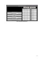
mcsSprinklers is available in three level of capability. The Basic Level Designed to perform manual and
automatic timed control of up to 24 valves for all of the Rain8 family of modules. It’s capabilities are
approximately equivalent to a 24 program timed irrigation controller with the added benefit of desktop and
internet access to provide for easy viewing and alterations of the schedules. It provides a rich user interface
including graphical, touch screen and the ability for remote valve control with PDA or X10 palm pad.
The Standard Level is designed to achieve water cost savings and provide a rich set of control options. It
takes into account weather conditions based upon internet data to both schedule when added moisture is
needed and to not schedule due to wind and/or rainfall conditions. It provides visibility into historical valve
activity and other parameters related to irrigation scheduling as well as all the features of mcsSprinklers
Basic.
The Professional Level is designed for maximum customization and options. It supports active backup and
email notification when attention is needed. Recordkeeping is enhanced with water use accounting and a
more complete historical calendar. Additional control is available for liquid nutrient distribution
(fertigation), use of moisture probes, and more flexible zone sequence control. Integration with other
automation is provided with direct weather station interfaces, IP-based control, and xAP messaging.
Support for the non-typical setups is provided in a unified manner that makes the complexity transparent.
It includes all features available with the standard and basic version.
9
This manual describes the full capabilities of mcsSprinklers. Not all features described herein will be
available with the Basic or Standard versions. It can be used as a guide to help understand what features
are available in each version.
mcsSprinklers will configure itself based upon the license level and based upon responses provided in the
setup interview. The intention is to minimize the complexity presented and only include features that are
being used. Features that are tailored out of the setup screens based upon interview responses can be
restored by using the “Expert Mode” setting on the Other Setup page. Features that are available with
higher level versions can only be made available by licensing the higher level version. During the trial
period the software can be configured for any of the three levels of capability so the level that contains the
desired features can be evaluated.
10
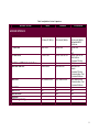
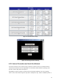
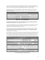
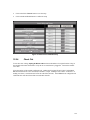
Table 1 mcsSprinklers Version Comparison
Software Version
Basic
Standard
Professional
HARDWARE INTERFACE
Host Platform
Windows
XP,Vista,W7,WHS,+
Windows
XP,Vista,W7,WHS,+
PC Interface
Serial COM
Serial COM
X10 Interface
ACK on Cmd
Ack on Cmd or Poll
Rain8Net and WiFi Master Interfaces
Rain8 Net and WiFi
1
Itemize Units
1
Itemize Units
Rain8 UPB
Yes, Itemize Units
Yes, Itemize Units
Rain8 X10
Rain8 X10-2
Rain8 Wireless
EtherRain
EPROM Programming
Yes
Yes
Yes
No
No
Yes
Yes
Yes
No
No
Windows
XP,Vista,W7,WHS,+
Embedded ARM
ArchLinux
Serial COM
IP
xAP
Ack on Cmd or Poll
Test Buttons
Command Timing
Multiple
Itemize Units
Search
Command Timing
Communication Test
Command Buttons
Yes, Itemize Units
Communication Test
Command Buttons
Yes
Yes
Yes
Yes
Yes
11
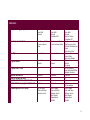
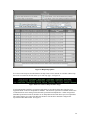
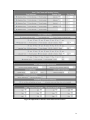
SCHEDULING
Control Strategy (Program)
Day of Week
Even-Odd
Interval
Day of Week
Even-Odd
Interval
Calculated ET
Zone Sequence Control
One Zone at a Time
in user-entered
order
One Zone at a Time
in user-entered order
Run Styles
Zone-to-Zone
Zone-to-Zone
Program Modes
Automatic
Manual
Automatic
Manual
Program Start Times
24
24
Duration Resolution
Areas (Program Variants)
Month to Month Time Adjustments
Global Multi-zone program adjustments
1 second
1
No
By Month
1 second
8
No
By Month
Scheduling Restriction Setup
Day of Week
Even-odd Days
Between Hours
Day of Week,
Even-odd Days
Between Hours
Wind Speed
Temperature
Rainfall
Day of Week
Even-Odd
Interval,
Moisture Probe
Calculated ET
One Zone at a Time
One Zone per Area
Multiple Simultaneous
Zones
External Control
Zone-to-Zone
Round Robin
Inter-zone Delays
Automatic
Manual
Syringing
24 per program
Sunrise/Sunset Offset
Variable Duration
1 second
8
Yes
By Month,
By Percentage
Day of Week
Even-odd Days
Between Hours
Wind Speed
Temperature
Rainfall
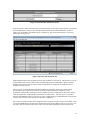
12
Rain Forecast
Pump Control
Water Flow Management
Yes
No
Yes
No
Water Source Management
No
No
Fertigation Control
Soil Moisture Determination
No
No
No
ET Calculation
Evapotranspiration Calculation
No
Hourly Weather
Internet-based Weather
No
Weather station-based Weather
No
AWS
Weatherunderground
NWS/EPA
AccuWeather
No
Rain Forecast
ET
External Discrete
Inhibit
Max Cycles
Between Hours by
Area
Log Restriction
Yes
Multiple valve control
to achieve optimal
pressure
Discharge Rate
Recharge Rate
Budget Management
Tank Management
Yes
Soil Efficiency
Adjustment
Crop Type Adjustment
ET Calculation
Moisture Sensor
Historical
Hourly Weather
Weather Station
AWS,
Weatherunderground
NWS/EPA
AccuWeather
Yes
13
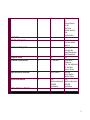
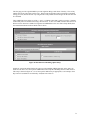
USER INTERFACE
Phone (Apple/Android)
Remote/Handheld Control
No
X10 Power line
Yes
X10 Power line
RF
Browser/Internet Access
Browser Style Customization
Graphical User Interface
Yes
No
Yes
Yes
No
Digital Pictures
Calendar-based
history
Touchscreen/Kiosk User Interface
Imperial and Metric Display Units
Control and Status Browser Views
600x800
No
Zone Status
General Status
Run Log
Touch screen UI
Scripting Automation Interface
No
600x800
Yes
Zone Status
General Status
Run Log
Run Projection
Touch screen UI
No
Yes
X10 Power line
RF
PDA
IPhone/Android
Selectable HTTP port
Yes
Digital Pictures
Calendar-based
history and status
Current weather or
other user-selected
status devices
600x800
Yes
Zone Status
General Status
Run Log
Run Projection
Touch screen UI
Yes
14
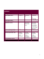
RECORDS and HISTORY
Wiring Color Record
Wire Harnesses
Zone, Area, and Site Digital Pictures
Water Use Accounting
Yes
3
No
No
Yes
32
Yes
No
Soil Moisture Trends
Valve Activation Logging
Number of Loadable Configurations
No
No
Unlimited
Yes
Yes
Unlimited
Historical Database
No
MS Access
Historical Calendar
No
Weather Items,
Soil Moisture Level
Runtime
Annual Trend Charts
Daily Detail Statistics
No
No
Yes
Yes
Yes
32
Yes
Measured
Calculated
Yes
Yes
Unlimited
Scheduled
MS Access
SQL Server
My SQL
SQLite
Weather Items,
Soil Moisture Level
Runtime
Water Use
Fertigation
Yes
Yes
15
SAFETY and BACKUP
Redundancy / Hot Backup
No
No
Min and Max Safety Intervals
Communication retry and failure
recovery
Internet Login Authentication
Email Notification
No
Yes
No
Yes
Self-Monitored
Multiple PCs
Yes
Yes
Yes
No
Yes
No
Yes
Yes
16
1.2 Acknowledgements
Version 1 of mcsSprinklers was introduced in 2003 into the Homeseer community. Many users provided
valuable feedback to improve the usability of mcsSprinklers. Of particular value was the diversity of the
needs and the operation in international locations. While all deserve acknowledgement, the memory of the
early days is not complete. A partial accounting is Bkphillips (Anaheim, CA), Cecil, DC, Degabe (Loomis,
CA), Droopyear (Szekesfehervar, Hungary), Frobnitz (France), JB Coulter (Visalia, CA), Jmonaco
(Rocklink CA), ka7gzr (Kent, WA), Mario from Spain (Madrid, Spain), Mountainman (CO, USA), Pete
(Lockport, IL), Smoothtlk (Metamora, MI), uberseer (Sugar Land, TX)
Version 2 of mcsSprinklers was introduced in 2005 with a mixture of Standalone and Homeseer users
providing ideas and assistance in making mcsSprinklers more user-friendly and feature rich. Version 2.6’s
new features are primarily the result of user suggestions and effort in assisting the incorporation. Scott
Bunker, Castle Rock, CO provided WeatherUnderground as an optional source of Internet-based weather
data as well as the Calendar popups. John Bonzey, Auburn, MA provided the handheld/Palm method of
remote control. Doug Behl, Nevada City, CA for the large site considerations such as the popup pictures
and area naming.
Some software components utilized within mcsSprinklers were obtained from internet sources. The tooltip
capability for context help was provided by Erik Bosrup’s overLIB. The graphical sliders were obtained
from Erik Arvidsson. Graphic icons were adapted from various sources including user contributions on the
Homeseer message board. The email facility was adapted from code posted by Gregg Housh.
17
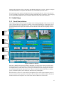
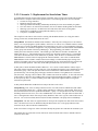
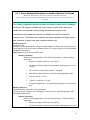
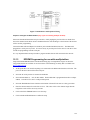
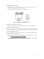
2 System Architecture
The system architecture uses a modular and incremental structure that leverages modern computing
technology, Internet, and low-cost interface electronics. The architecture is scalable from a single value
residence controller to a very large commercial controller. It can operate within an existing small personal
computer to minimize cost or run as a network of computers to maximize reliability.
The personal computer provides a dramatic improvement in the user interface in the operation of a
sprinkler controller vs. dedicated controllers. The use of the Internet also provides a dramatic improvement
in the efficiency of commercial and residential irrigation.
The two primary components to the irrigation controller are the electronic control of the sprinkler zone
valves and the optimal scheduling of water distribution. Small Rain8 modules perform the electronic
control. Each of these can control eight watering zones with wiring from the zone valve to the Rain8
module being the same as the wiring to traditional timed controllers.
The watering schedule is determined on the PC and this schedule is conveyed to the Rain8 modules in one
of three mechanisms. This can be with a direct cable connection, an interface using existing house wiring,
or a wireless radio frequency interface. The scheduling is setup by the user with a rich interactive interface
and is augmented with real-time information about environmental conditions from the Internet.
This basic architecture is augmented with the ability to monitor local conditions with sensors such as a
water flow meter, manually control the zones with a handheld remote or voice, add redundant components
to accommodate unexpected failures, and use the Internet for off-site control and monitoring.
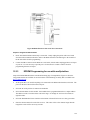
This architecture is pictorialized in Figure 1 System Architecture.
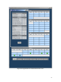
18
Figure 1 System Architecture
2.1 Controller Selection
The selection of a controller will depend primarily upon the means of physical connection that is most
viable for a particular site. There are advantages and disadvantages with each option available.
Powerline connections are typically the easiest to retrofit since the powerline connection will be available
at many locations. The powerline is shared for many uses and the potential exists that interference with
communication can exists using the same shared wiring. X10 and UPB interfaces to the powerline are
available. The X10 is lower cost and the UPB is more robust. In the X10 case there are two models. One
provides a communication path to command a valve while the other provides both command and status.
19
The status is used to assure the command was received. The UPB provides both command and status. The
Rain8UPB also provides a counter input that can be used to measure water use if a digital meter is available
at the site.
At some locations a LAN is prewired and this makes for a very robust connection and is the most desired
one from a reliability perspective. The EtherRain and Rain8Net via an IP/Serial adapter can be used in this
environment. Variations of this are WiFi where the wired LAN is bridged with RF to allow
communications over the air in a range of around 50 ft. The Rain8Net provides a counter input for water
use measurements and allows each of the eight valves in the module to be independently used for zone
valve, fertigation valve, and pump valve control. The EtherRain is able to only able to activate one of the
eight zone valves at a time, cannot be used for fertigation valves, and pump control needs to be managed
with the 7/1 variant of the EtherRain. These control restrictions affect the ability to run multiple zones in
parallel to manage water flow rates.
The Rain8Net can also be used with a direct RS-232 wired connection between the computer and the
controller. Since it is a dedicated wire it has good communication reliability. When the computer and the
controller are in the same proximity then the addition of the direct wiring may not be burdensome.
Consideration is also needed for the ability of the computer to support a RS-232 interface as many modern
ones only support USB. If USB/RS-232 adapters are used care should be used to select ones that have
good software driver support for the operation system to assure reliable communication.
20
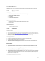
3 Installation
3.1 Standalone
3.1.1 Windows PC Host
The installation is performed with execution of the downloaded setup.exe or setup_service.exe program.
When either is run it will create a folder and install all necessary components under this folder. The default
install location is C:\Program Files\mcsSprinklers for the standalone version or C:\Program Files\Homeseer
PRO for the Homeseer plug-in version.
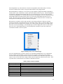
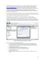
For the standalone install a tray icon is available to provide a quick user interface to mcsSprinklers. See
Figure 2. For the non-service install this tray icon is required and it is optional for the service install. It is
normally the case that the tray icon interface is started when the user logs into the computer. This can be
automated by placing a shortcut to mcsSprinklers_Tray.exe in the user’s startup folder.
Following a service install the computer will be setup to automatically start the service when the computer
starts. The service will not be running immediately after the install. It can be started by restarting the
computer or by starting the mcsSprinklers service. While different versions of Windows have different
ways to manage services, the following for WHS will be similar on others. Right-click Computer, Manage
Computer, Services and Applications, Services, Right-click mcsSprinklers, Start.
When the mcsSprinklers service is started or when it is stopped an entry will be made in the Windows
Event Log under the Application events. mcsSprinklers does not use the Windows Event Log for any other
purpose. Events reported by mcsSprinklers will be local via browser on the Messages Page and available
in text file in subfolder C:\Program Files\mcsSprinklers\HTML\mcsSprinklers\Data\StartupTrace.txt.
To install the tray icon on individual user login the file mcsSprinklers_Tray.exe should have a shortcut
placed in the user’s startup folder. This folder can be reached with Right-click on Start button, Explore,
Programs, Startup. mcsSprinklers_Tray.exe will be in C:\Program Files\mcsSprinklers folder if a default
install is performed. Rather than placing the icon in an individual user’s startup folder it can be place in the
All Users folder so it will be available to all users upon their login.
When running on Windows version starting with Vista enhanced security needs to be considered.
mcsSprinklers must be “run as administrator” since it communicates with hardware resources. When User
Access Control (UAC) is enabled then a user prompt will be presented to confirm startup intent with the
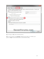
additional privileges. This prompt is usually not desirable, especially with unattended restarts. This can be
overcome with a shortcut that enables elevated operation. A tutorial is provided at
http://www.sevenforums.com/tutorials/11949-elevated-program-shortcut-without-uac-prompt-create.html
An extract from this location is embedded at the end of this manual.
mcsSprinklers_Tray.exe can also be placed to run on any computer on the LAN to gain access to
mcsSprinklers that is installed as a service. For this situation the tray option for “Tray Setup” should be
used to change the address of where mcsSprinklers service is running. The default is the local computer,
but can be changed to any computer name or IP address where mcsSprinklers service is running. The port
selected on this setup needs to be the same as the used by the mcsSprinklers service. The default is 8008,
but can be changed as part of the mcsSprinklers setup. Select the “Tray Setup” option again from the tray
to close the setup form.
When remote access to the computer either through the LAN or WAN is desired then the firewall on the
computer where mcsSprinklers is installed needs to setup to allow mcsSprinklers passage. This is true for
the remote tray icon or remote browser use in general.
21
The mcsSprinklers Tray will monitor the execution of mcsSprinklers when either locally or remotely
referenced. Should it loose contact it will provide this indication with a popup balloon.
When mcsSprinklers is running as a service the Tray setup should be configured to Inhibit mcsSprinklers
Launch Control. This will make the “Launch” option unavailable from the tray icon. When mcsSprinklers
is installed as a desktop application rather than as a service then the tray icon can be used to control the
execution of mcsSprinklers. In a normal setup the shortcut to mcsSprinklers_Tray.exe will be placed in the
startup folder and the tray launch control will be set to Auto start mcsSprinklers when the tray icon is
started. This Auto start can be defeated with the “Manual” selection for launch control. Execution start
and stop then will be through user action of the tray icon options.
When the tray is available it will be used to provide event message notification. When an event that
warrants user attention is raised then the tray icon will change color to amber. It will also change color to
green when at least one irrigation zone is running. For events a popup will appear for 20 seconds or until
the mouse is used to acknowledge it. The Message Page is shown to display the events in a static format.
Once the event is acknowledged the tray icon will change back to the blue or green color within sixty
seconds unless further events are reported.
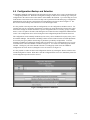
Figure 2 Desktop Tray Access to Status Pages
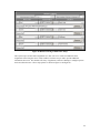
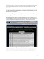
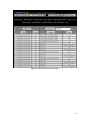
For a basic installation this is all that is required. For a distributed installation there are six applications
that are available in the standalone version to be run on any computer on the local network. During
execution of the setup.exe program checkbox options are available to select individual components. The
setup.exe can be run on each remote computer and the desired components installed at that location. Table
2 provides the list of functions that are available for distributed execution.
Table 2 Software Interface Modules
Interface Component
xapmcsCM17A
xapmcsCM11A
xapmcsRain8Net
xapmcsUPB
xapmcsW800
xapmcsCM19A
xapmcsVoice
xapmcsWeatherAWS
xapmcsWeatherXML
Description
PC interface to control one or more Rain8-Wireless modules
PC interface to control one or more Rain8-Power line modules
PC interface to control one or more Rain8Net modules
PC interface to control one or more Rain8UPB modules
PC interface to accept handheld remote control inputs from W8800
PC interface to accept handheld remote control inputs from CM19A
PC interface to accept voice commands and speak status
PC internet interface to obtain current weather conditions
PC internet interface to obtain forecasted weather from Weather.com
22
xapmcsHub
Traffic router for applications on same PC
3.1.2 Embedded Platform
The embedded platform comes with mcsSprinklers and associated operating system files preinstalled on a
USB flash drive. This drive is inserted into any USB port on the platform. A network cable and power
cable are inserted into their appropriate jacks.
After a short delay the status light on the front will start blinking and within 30 seconds after it stops
mcsSprinklers will be ready to accept requests from a browser. The network node name will be
mcsSprinklers and the IP address will be provided by the DHCP server on the LAN. This means there
needs to be a DHCP server and this is normally the router that provide access to the internet.
The default port is 8008 and the IP is available from the DHCP server (router) or from the ARP table. The
ARP table can be viewed from a command prompt (run cmd from Windows Start) with the command “arp
–a”. Use the MAC address printed on the bottom of the embedded platform to identify the specific IP
associated with that address. Any valid mcsSprinklers page can be used as the initial routing will be to the
registration page. For example, http://192.168.0.101:8008/status would be a browser URL to get initial
access to the embedded mcsSprinklers if the DHCP server assigned 192.168.0.101 as the IP address.
3.2 Homeseer
For the Homeseer install the Homeseer Updater is used to assist in the installation. In this case care must
be exercised to assure that the install is placed in the correct folder where Homeseer is running as different
versions of Homeseer run in different folders. The menu items available in the standalone tray icon are
available from the Homeseer menu where the Homeseer log is displayed.
When installation is performed on a Homeseer PRO-100 or similar processor then one needs to be aware
that the C drive, where the system files are stored needs to be explicitly unlocked to allow files to be saved
to this drive and this unlocking operation needs to occur prior to installing mcsSprinklers. After installation
it can be write-protected again. If this step is not performed then the install will not persist during a power
cycle of the PRO-100 or Hometroller.
3.3 Registration
mcsSprinklers is licensed to run on one computer. It will operate on a trial basis for 30 (Homeseer) or 45
days (Standalone) and after that time it will no longer startup until registration is performed. The
registration process will depend on whether mcsSprinklers is run standalone or as a plug-in to Homeseer.
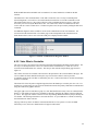
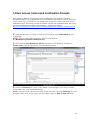
3.3.1 Standalone
mcsSprinklers provides a user interface via a web browser. The browser can be launched from a user
desktop or Start menu and the URL completed to reference mcsSprinklers or it can be done from the
mcsSprinklers tray icon if it is installed. See Figure 2. The default URL for registration is
“http://localhost:8008/registration” with the browser launched from the same computer as the installed
mcsSprinklers. This default can later be changed as part of the setup. Any status page request from the
tray icon will also result in a registration page if registration has not been completed.
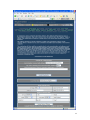
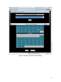
Until registration is completed the only page that is avaialble from mcsSprinklers is the registration page so
all other page requests will redirect to the registration page. The blank registration page is shown in Figure
3. Registration can be performed directly with the product serial number supplied with the purchased
software. It can also be done by contacting customer service and providing proof of purchase information,
Computer ID and Disk ID to obtain an unlock code.
23
Contact information of your choosing (e.g. name) can be entered so that customer support can identify you
in the case that you misplace the registration information and the software is to be installed on another
computer.
The zip code may also be entered at this time so that the proper environmental conditions can be setup or it
may be entered later in the mcsSprinklers setup process on the “Others” setup page.
The registration information entered on the registration form is submitted using the “Register Now” button
at the bottom of the form. This will transfer the information to the internet address identified as the
Registration URL where it will be validated and retained for permanent records. No other information,
except that shown on the form is transferred to this site.
On the embedded platform the registration page also contains settings to identify the time zone and the
network setup. The network should be setup before attempting to register since mcsSprinklers needs access
to the internet to perform the registration. To get access to the registration page from a browser there needs
to be a DHCP server on the LAN to assign an IP address. The embedded computer network name is
mcsSprinklers. If the embedded platform has wWiFi capability then the setup for the wireless network will
also be shown otherwise only a wired network setup will be available.
24
25
Figure 3 Standalone Registration Page
3.3.2 Homeseer Plug-in
When used as a Homeseer plugin, the registration process is managed by Homeseer Technologies
(http://www.homeseer.com).
Three plugins are available and only one of these can be enabled. The plugin is a function of the license
obtained and will be mcsSprinklersB (Basic), mcsSprinklersS (Standard) or mcsSprinklersP (Professional).
The process is normally started by downloading the mcsSprinklers plug-in using the Homeseer updater.
After the download is complete the Setup tab and then the Interfaces tab is selected to view the list of
available plugins. The plugin will require either a registration key from Homeseer Technologies or can be
activated using the Trial button. Once the trial button is selected, the enable link is activated. You may the
click the grayed Enable button. The selection is then saved with the Save button. An enabled
configuration setup for the Basic version is shown in Figure 4.
Figure 4 Homeseer Licensing of mcsSprinklers
3.4 Startup
Following validation of the registration or the trial, mcsSprinklers will initiate its startup initialization.
During this time it provides significant checks to assure data is consistent. While checking and when not
running as a service it will show a splash screen such as Figure 5. At the bottom of the screen will be a
progress bar that shows its relative progress and segment it is processing.
Figure 5 Startup Splash Screen
26
Following this check there will be a short delay while Windows manages its resources. Startup is complete
when the mcsSprinklers icon appears in the Windows tray at the bottom right of the screen.
When performing setup operations mcsSprinklers looks for unexpected behaviors. Since it does not want
to save a potentially corrupt setup it will not save changes made while errors are detected. The message log
or the General Debug output file will provide further information about detected inconsistencies.
3.5 Initial Setup
3.5.1 Visual User Interface
The setup for various scenarios is shown by example in the remaining paragraphs of this section. Once the
setup is complete the user has the option of visibility of finest details maintained by mcsSprinklers via the
General Status, Zone Status and Run List pages. These views provide the visibility when needed, but for
general operations for the majority of users the visual user interface will be the most frequently used view
(Figure 6).
Select a
Zone
Zone
Running
Status
Control
Selected
Zone
History
and
Forecast
Figure 6 Visual User Interface
Each zone is identified by name and visually by photograph. The large arrows at the top scroll the zones
until the desired zone is positioned in the center location with the black border. The selection can also be
accomplished directly with a mouse click by clicking one of the dots below the photographs. These dots
are in positional order and each represents a zone. They are colorized to identify when they are running
(green), are disabled (yellow), have failed (red), and not currently running(blue).
When the mouse is placed over a zone status dot the rightmost picture will be replaced with the picture of
the zone where the mouse is positioned. This allows the row of dots to be scanned to find the desired zone
and then clicked to have the picture move to the center and it will then be the selected zone.
27
When the mouse is placed over the selected (middle) picture then the leftmost picture will change to a
picture of the area in which the zone is located. This allows a context to be identified easily for larger
installations. When the mouse moves away from the center selected zone picture then the prior zone
picture will be restored.
When a zone is selected, adjustments to the settings for the zone can be made with the slider controls.
These sliders will change the setup information on the Zone Setup and Area Setup pages. Either this
graphical control or the setup pages can be used to accomplish the same changes. A more detailed setup
with more options is available from the setup pages.
The scheduled irrigation program is the “Auto Program”. This program will be run based upon the control
strategy setup in the Area Page. One of the auto program parameters is the duration that a zone will run.
There are actually three parameters that determine the actual run time of a zone. One is the Zone time, one
is the Area time, and the third is the Site time adjustment. The Zone time is the nominal time that a zone
will run at the peak of the irrigation season. To account for seasonal variations an Area time factor is
applied to this base Zone time. For example, in October the duration may be reduced by 30% from the
nominal July duration. A Site adjustment is also applied to allow all times to be adjusted upward or
downward by the same percentage.
The touch screen interface provides access to the Zone time adjustment in the Auto Program column. The
slider changes the Zone time with the number being shown actually being the composite of the Zone time,
Area factor, and Site factor. For example if the Site adjustment is +10% and the Area factor is 70% and the
nominal Zone time is 50 minutes, then the slider will show (50 * .70 * 1.10) 39 minutes. If the slider is
adjusted to 20 minutes then the nominal Zone time will change to (20 / .70 / 1.1) 14 minutes. After
changing the Auto Program slider to 20 in this example, then going to the Zone Setup page one will see a
value of 14 for the Zone Auto program time. The number that is seen on the slider is the number of
minutes that the zone will actually run based upon the other setup information.
There is also a slider under the Manual Program column. This slider is used to change the timeout duration
for a zone when the zone is controlled manually. Manual control can be with a handheld device or from the
browser. The time set for the manual duration timeout has no effect on the auto program times. If the
manual time is set to zero then the zone cannot be manually controlled.
A control button is provided under the Manual Program slider. This button toggles between Run and Stop.
When the Run button is activated then the manual program for that zone will be started. It will run the
zone until the zone is stopped or until the manual program duration timeout is exceeded. When the button
shows “Stop” then it will stop the currently active program for the zone. This means the zone could have
been started manually or automatically and the same button is used to stop that zone from continuing.
Rather than stopping a zone it is also possible to pause the current program so that it can be resumed a short
time later. That is done by using the “Pause” button. When selected, this button will toggle to read
“Resume”. When “Resume” is selected then the current program will continue from the point it was
paused.
Next to the Pause/Resume button is the “Skip” button. This button is used to skip all zones in tomorrow’s
auto program. In essence it tells mcsSprinklers to not automatically run any zones even if they were
scheduled for tomorrow. When the Skip is active then the button will change to “Allow” and the decision
to not irrigate tomorrow can be rescinded.
There is a slider under the Current Status column. The value showing on this slider represents the
percentage of soil moisture saturation. mcsSprinklers keeps track of the soil moisture content based upon
weather information and the irrigation performed. When the control strategy is setup on the Area page to
be one of the timed modes then soil moisture content is only informational and changing it with the slider
has no direct effect. When the control strategy is based upon calculated soil moisture then a change of the
slider will have a direct effect on the next irrigation time for the zone.
28
The next scheduled times for the currently selected zone as well as the time that the next scheduled zone
will be run are shown under the area labeled “Next Schedule”. As the schedule changes or as zone
completes its cycle the status information is updated to reflect the most current information. When the
mouse is positioned over the “Auto Program” label at the lower right of the page a popup will appear that
occupies most of the screen. This will show the full program with the zones listed in the order that will be
run. The current soil moisture levels are also shown on this popup.
The screen updates are performed immediately upon user control of the buttons or sliders. It is updated a
few times per minute as the irrigation schedule progresses. There are occasions where a browser looses
sync with its server and the updates will stop. There is a small double arrow icon in the upper left of the
page that can be used to refresh the screen to assure the information presented is the most current.
The currently active zone will automatically be shown as the selected zone when that zone starts its cycle.
The status dots will update, as will the slider information about the selected zone without the need for a
page refresh. The same is true for the Next Schedule information as it changes.
The current time and weather information is shown in the Current Status area. This information is updated
as new weather data becomes available. The clock runs continually. The temperature and wind speed
buttons can be selected to popup an annual trend chart showing either the temperature or wind speed trends.
This annual information is available for all weather data and zone valve control information when accessed
from the calendar from either the General Status or Zone Status pages.
The “Time Remaining” display at the center of the screen shows the number of minutes that are remaining
to be run for all zones that are currently scheduled to run at the current time. It is updated each minute as
the time counts down.
A three or four week window into the selected zone’s activity is shown in the lower left. The calendar
shows each day the zone was run with a green sprinkler graphic and each day it had rained with a blue
raindrop graphic. The weather forecast is shown for the next week and a blue sprinkler graphic positioned
in the day of the next scheduled irrigation for the zone. A mouse click on a cell in the calendar will popup
more detailed information about that day.
The two small icons are at the top right and left of the page are navigation controls. The refresh icons were
previously described to refresh the current display’s information. The icon on the upper right is used to get
access to the other mcsSprinklers pages. From these pages additional setup can be done or more detailed
status information gathered.
The top of graphical display contains three panels that will show different information based upon where
the cursor is hovering on the screen. Figure 7 shows the three views. In all views the center panel shows
the currently selected zone. The selected zone is the one where the remainder of the screen shows
information and allows settings for this zone to be changed.
The top view is default view when the cursor is not positioned in a critical area. It provides the time of day
and up to six current measurements. The measurements to be shown are user-selected from the General
Status page.
The middle view is shown when the cursor is positioned over a colored dot (Figure 6). These dots are
located immediately below the three panels. Each dot corresponds to a zone. The current setup for the
zone is shown in the left panel. The right panel shows a picture of the zone.
The bottom view is shown when the cursor is positioned over the left or right scrolling arrows. It shows the
picture of the zones that will move to the center panel position with a click of the right or left arrow button.
29
Figure 7 Views Available from Graphical UI
3.5.2 Quick Start – Learn by Example
When mcsSprinklers is started it will place itself as a small icon in the lower right tray of the PC desktop.
The icon will be a blue or green base with water drops rising. Blue indicates that no zones are currently
being watered and green when any zone is active. When the icon is clicked it will expand to show a menu
of setup and operational selections. When used as a Homeseer plug-in then this icon is not available, but
access is provided through the Homeseer menu.
The general setup flow is numerically identified in the popup menu. In some cases there is a dependency
on the setup sequence, but in general any setup page can be edited at any time and in any order. The
dependencies that exist relate to identification of a valve interface before the valve can be wired and the
identification of how the valve is wired before it can be used in a control zone. This means that the
Rain8/Devices setup needs to be done before the Wiring setup and the Wiring setup done before the Zone
and Area setups.
A browser interface is used for each setup and control page. This means that the setup can be done from
any location to which the PC has network connectivity. It also means that entries made on a page are not
recognized until the “Save” button on top of each page is clicked and the screen redrawn.
Navigation among the various pages can be done from the tray icon / menu or it can be done from the links
located at the top of each browser page.
30
To illustrate the basic setup flow a few scenarios will be used to base the setup actions. The first will be a
minimal setup of one zone to be watered for 30 minutes every other day. Two other scenarios will be
shown to illustrate some of the setup features.
Some of these scenarios are available as preconfigured setups that can be selected as the first item in the
Setup Interview. The interview is selected from the tray icon.
3.5.3 Sample Scenarios
3.5.3.1 Scenario 1 – One Zone Setup
A Rain8-Wireless unit is being used to control a single zone on a schedule of 30 minutes every other day.
The computer has a CM17A/Firecracker installed on Com Port 1 to control the Rain8-Wireless.
Select Setup1-Rain8. Choose Rain8-Wireless to identify that the Rain8-Wireless is being used. It comes
from the factory programmed as Unit B1 with timeout of 60 minutes in each zone. This is adequate for use
in this scenario. If it were not then the Timer setup at the bottom of the page would be used to configure it
as desired.
Enter 1 in the Module PC Interface group, Wireless port box to configure the CM17A/Firecracker to use
port 1.
Click the radio button at the intersection of house row B and bank 1 to select the Wireless module type.
This means that the module’s valves will be associated with addresses B1 through B8. Click Save button at
the top to record these settings.
Select Setup2-Wiring. To identify the wire connection between the valve and the Rain8 module,. let us
assume that the valve is connected to the Red wire and we will be using the second position on the module
(B2) for this valve. The first column’s pull down is selected to be RF B2. The second column contains a
box to label this valve. Let us call it Lawn and enter this name in the box. Click the Save button.
At this point the Rain8 interface has been defined and the wiring to the valve located in the Lawn has been
specified. The next step is to describe when to turn the valve on. The next step is on the Setup4-Zone
page where the duration of 30 minutes is identified. There are twelve rows in the Area 1 group and any of
these rows can be used. Select the pull down to pick the RF B2 Lawn valve. Enter 30 in the Auto minutes
box. Click the Save Button.
Select Setup5-Area. A setup page for the areas will appear. We will use the Area 1 for this scenario.
Click the radio button at the top for this area that identifies it to be an interval strategy. It is one of the five
possible selections. Enter 2 in the box below it since the interval is every other day or 2.
This completes the setup for the scenario of a single value using a Rain8 Wireless controller that is
scheduled for watering for 30 minutes every other day. The zone will be watered starting at midnight every
other day.
3.5.3.2 Scenario 2 – Basic Homeseer Setup of Two Sprinkler Valves
mcsSprinklers is added to an existing Homeseer configuration where the sprinkler valve interface is the
Homeseer X10 interface or virtual devices through other Homeseer plugin. A relay mapped to [1 and an
appliance module at M16 will be used to control sprinkler valves. The valves are to be activated for 40
minutes each on Monday, Wednesday, and Friday and not allowed to be run between 10:00 AM and 4:15
PM
31
Select Setup1-Devices. To identify the devices that are being used, in the section titled “Homeseer X10-IO
Devices” enter [1,M16 in the text box. Note the comma to separate the two virtual devices. No entries
need to be made on any other boxes on this page since the control interface to the hardware is via
Homeseer.
Click Save button at top to record these settings.
Select Setup2-Wiring. To identify the wire connection between the valves and the devices let us assume
that the valves are connected to the Red and Blue wires in the wiring harness. Select the row where the
wire color is red and from the pull down select [1. In the Location column give it a name. This name will
be used to set the name of the Homeseer device.
Click Save button at top to record these settings.
Select Setup4-Zone. Since both valves are on the same M/W/F schedule they can be placed in the same
zone. In the valve column select two rows and each valve. In the Auto Minutes column enter 40 for both
since that is the duration the zone will be run each time it is activated. Soil Efficiency and Rain Factor will
contain default values that do not need to be changed. They are used for control modes based on soil
moisture content.
Click Save button at top to record these settings.
Select Setup5-Area. A setup for one area will be presented. It will show the zones associated with the
area at the top and the 30/7 day history for the zone. The history will initially be blank. The M/W/F
schedule is selected by clicking the “Day-of-Week” radio button and the check boxes for Monday,
Wednesday, and Friday.
No specific start time is needed so the Area start times need no entry. No pump is specified so no entry is
needed in this section either.
Click Save button at top to record these settings.
Select Setup6-Restrictions. A variety of restrictions can be imposed. In this case the desired restriction is
entered into the “Don’t between hours” with values of 10:00 and 16:15
Click Save button at top to record these settings.
Select Setup9-Other Setup. The browser interface to mcsSprinklers can be serviced by the plug-in or by
the Homeseer server. Select the desired radio button.
Real time weather data and forecasted weather as well as nominal seasonal percentages are based upon the
zip code. Enter the zip code and click the Save button. The screen will be redrawn and available local
weather site will be presented in the Time and Weather Setup section. Select at minimum, the primary site
and backup sites if desired.
Near the bottom of the page are some setup options specific to Homeseer. The device codes shown for
Manual mode and Seasonal control are moding devices. One toggles between manual and automatic
modes and the other toggles between plug-in Enabled and Disabled. The display options relate to how the
Homeseer Device Strings are formatted and the overall appearance of the browser page. The Database
option allows selection of Microsoft Access vs. SQL Server for retention of historical information.
32
3.5.3.3 Scenario 3 - Replacement for Stand-alone Timer
A standard timer normally used for timed control of sprinkler zones is being removed and replaced with a
Rain8 to achieve computer control of the sprinkler zones. The following objectives are to be satisfied:
1. 4 Zones are being controlled
2. Rain8-Net used for valve control
3. Watering scheduled for Monday, Wednesday and Friday for Lawn areas and daily for garden
4. Two lawn zones to be watered for 60 minutes, one for 30 minutes and the garden for 20 minutes
5. Watering cycle to start at 2:15 AM for the lawn and 1 hour after sunrise for the garden
6. Garden water is supplied by a pump while the others by city water
7. Com port 2 is available on the PC
The setup flow is the same as with scenario 1 starting with the Rain8 interface, its wiring, the control
strategy for the areas, and the durations for the zones.
Setup1-Rain8. The Rain8-Net module needs an address. Since only one is being used, we can search to
find it, or we can just program a specific address. In this case we will set it to 1 and then search to confirm.
The first step is to remove the Rain8 module from connection to any valves. The programming of the unit
cannot be done in an “installed” configuration. All programming is done from entries made in the EPROM
Timers group at the bottom of the Setup1-Rain8 page. The programming port number is selected to
identify the serial connection to the PC. The module type radio button is selected to be Rain8-Net. The
address box entry is 1. The timeout/safety times will be set to 80 in this scenario since it is a reasonable
value above the maximum time of 60 minutes that is planned. After all entries are made then the Write
EPROM button is clicked. This will reprogram the connected module. After a few seconds the Read
EPROM button can be clicked to read back the current settings to confirm that the proper settings were
applied. The module can be removed from the programming port now and connected to the port that will
be used for normal operation. These may be the same ports and in this case no move is required.
At this point we know the Rain8 module’s address is 1 so we can do a search and know what to expect.
The search is done from the top of this same page. First the Rain8-Net interface port is identified to be 2 in
the Interface group. This is the port that will be used to communicate with the Rain8-Net in a normal
operational setup. The second group on the page contains two buttons. The rightmost one is clicked to
start the search. The page will be redrawn with a window between the two buttons. A value will increment
in this window to show the current address that is being searched for Rain8-Net modules. In this case we
do not expect any after 1, so when a number greater than 1 appears the rightmost button can again be
clicked to stop the search.
At this point the Rain8-Net module has been setup to interface to the valves.
Setup2-Wiring. Four valves are being connected so four wires will need to be identified to mark which
wire is connected to which valve. A pump is being controlled so a fifth wire is also needed. If they are in
the same harness then all can be specified in the Harness 1 group. Use the pull down on each row to make
the linkage between water valve, wire color, and Rain8-Net valve control. The pull down will show NET 1
Valve 1 through 8 since that is what was previously identified. Each valve is given a name in the boxes on
the rows. Let us use Front Yard, Back Yard, Flower Bed, and Garden. The pump will be called Pump.
Setup4-Zone. The four zones are organized into two areas per the setup that was done for the Area control
times. The three lawn valves are identified with pull-downs in the Area 1 zone group and Auto times
entered as 60, 60, and 30 in the three identified rows.
In the Area 2 Zones a single row will be selected to identify the garden valve and enter the 20-minute cycle.
The manual times for each of the 4 zones will also be entered with the same values so manual control of
each zone can be done.
33
Setup5-Area. The lawn requires a M-W-F schedule while the garden requires a daily one. This implies
that two areas need to be defined. The first will be for the lawn zones. The control strategy is selected to
be Day-of-Week with the radio button at the top. The Monday, Wednesday, and Friday checkbox are
checked. Watering is to start at two hours 15 minutes before sunrise, so -2:15 is entered into Time1 box
with a relative to sunrise selection.
In Area2 the Interval radio button is selected and a value of 1 for the interval. The entry in the Time1 box
will be 1 and the radio button checked to the time will be relative to sunrise. This area has a pump so the
pull down is used to identify the wire connected to the pump.
Setup8-Weather. Since the time specified for the garden is relative to sunrise there needs to be location
information entered so mcsSprinklers can computer sunrise and sunset times. This is done from the
Setup8-Weather page with an entry in the Zip Code box. Since weather information is not needed the
Internet download method can be set to Don’t Download Weather and Forecast Data.
34
3.5.3.4 Scenario 4 - Typical Use of Features
A typical scenario will go beyond the setup for the quick start. The following example illustrates the setup
the achieves the following objectives:
1. Sprinklers enabled in 15 zones of lawn when soil moisture below 0.5 equivalent rain inches
2. Sprinklers enabled every other day for 3 zone garden
3. Water can only be used for irrigation on even days of the month
4. Sprinklers disabled during the heat of the day
5. Sprinklers disabled when it is windy
6. Sprinklers disabled if rain forecasted within two days
7. Only enough water pressure to do one zone at a time
8. Need to do a precheck of the zones to confirm all valves and heads are in order
9. Rain8-X10-2 units to be used
10. Pump used for all irrigation
Setup1-Rain8. Similar procedure as in the prior scenarios with a caveat that the Rain8 X10-2 units need to
be programmed with different house/bank codes. Assume the programming is setup for N1 through N8 and
N9 through N16 to handle the 15 lawn zones. M1 through M8 for the garden zones. In the case of the M1
through M8 module it needs to be configured to use Valve 8 as the pump control. When all the three units
have been programmed there will be 23 available zones and 1 pump, which is adequate for the 18-zone
requirement.
No other X10 automation controller exists so the X10-2 modules can be configured in the optimal Ack on
Cmd and Poll configuration and the default 5 seconds between commands is acceptable setup for the
X10/RF Interface section.
Setup2-Wiring. Similar procedure as in other two scenarios.
Setup4-Zone. Similar procedure as in the other scenarios, but in this case we are also concerned with the
ability to manually control the valves for only short duration testing. Because of this a time should be
entered for each of the Manual time boxes that are being used. When a valve is turned on manually then it
will run for the Manual time number of minutes or until it is manually turned off.
Setup5-Area. Similar procedure as in the other scenarios. In this case, however the control strategy for the
lawn is selected to be calculated with the radio button and the threshold box under it is set to be 50%. For
the Garden and Lawn the pump will be selected
Since the water pressure is limited then only one zone should be watered at a time. This specification is
made in each of the two area sections of the page to specify that the sequencing is part of a single master
sequence. If the checkbox is unchecked then the two lawn areas will be watered in parallel rather than in
series.
Setup6-Restrictions. A variety of restrictions are imposed in this scenario. Each of these is entered on
this page. The “heat of the day” limitation can be coded in the Between Hours boxes. Perhaps values of
11:00 and 18:00 would be appropriate times to not allow watering to occur. “Windy” may be translated to
a value of 10 MPH for 5 minutes. This means that over a 5-minute period the average wind speed must be
less than 10 MPH. Forecasted precipitation implies a reasonable probability of rain. An entry of 50
percent, 2 days, and the corresponding checkbox will result in a watering restriction if either of the next
two days has at least a 50% probability of precipitation.
Setup7-Remote Control. The ability to pre-check the valves implies manual control, but also may imply
the use of a remote control pad. The remote control pad will send RF codes consistent with X10 protocol
and these need to be received and associated with specific valves. There are 18 zones so 18 discrete
House/Unit code values will need to be entered. For simplicity the unit codes should be the same as the
35
valve codes. This means something like K1 through K3 and L1 through L15 could be entered into each
box on the Remote Control Page.
Remote input also implies an interface to remote signals. A W800 is attached to COM2 as the RF receiver
so 2 is entered for the W800 port.
Setup8-Weather. The wind speed data is obtained from a local reporting station. The available stations
are contained in the pull downs in the Weather group of this page. The stations are associated with zip
codes so a change in zip code will change the list of available stations. Up to three stations can be specified
to handle the cases when a station happens to be inoperative.
36
3.5.3.5 Scenario 5 – Dual PC – Dual Hardware Interface Configuration
The dual PC configuration will build upon Scenario 4 setup by showing the additional considerations for
the redundant configuration. There are a variety of redundant configuration setups. This one will assume
the following hardware;
Two CM11A Power line interfaces
Two W800 RF Interfaces
Two Computers running in Active/Standby irrigation mode
Computer 1 name is MAIN and contains CM11A interface and W800 interface
Computer 2 name is GARAGE and contains CM11A interface W800 interface
Same Rain8 controller hardware as scenario 4
The setup will be performed on the primary computer first and then when completed a few changes will be
made from the secondary computer. The following applies to the primary computer (MAIN). This
computer needs to have the folder where mcsSprinklers is installed to be shared over the LAN. Consult
your Windows operating system documentation to make this folder shared.
Computer # 1 (MAIN)
Setup1-Rain8. No Change
Setup2-Wiring. No Change
Setup4-Zone. No Change
Setup5-Area. No Change.
Setup6-Restrictions. No Change.
Setup7-Remote Control . No Change
Setup9-Other. Redundancy backup mode selected as “Standby Backup”. This will cause a blue highlight
to the middle of the Others page when the Save is clicked.
Computer #2 (GARAGE)
On the second computer (GARAGE) the mcsSprinklers application is started after the computer # 1 setup is
complete. This will allow the sharing of the setup that was previously done. It can be changed from either
computer at any time and both will be updated.
Setup9-Other. Redundancy backup mode selected as “Standby Backup”. This will cause a blue highlight
to the middle of the Others page when the Save is clicked. Note the backup mode setting is the same as on
the first computer. The setup entries shown in blue are not shared so each needs to be made individually on
each computer.
Redundancy Backup Mode\Path to primary mcsSprinklers edited to change the computer name (GARAGE)
to (MAIN). This path is where the configuration information is stored. It will be stored only on one
computer and MAIN was selected to be the primary. After editing it will show as \\GARAGE\C\Program
Files\mcsSprinklers.
37
3.5.3.6 Scenario 6 – Dual PC – Single Hardware Interface
Configuration
The dual PC configuration will build upon Scenario 4 setup by showing the additional considerations for
the redundant configuration. There are a variety of redundant configuration setups. This one will assume
the following hardware
One CM17A Wireless interface
One W800 RF Interface
Two Computers running in Active/Standby irrigation mode
Computer 1 name is MAIN and contains CM17A interface
Computer 2 name is GARAGE and contains W800 interface
Same Rain8 controller hardware as scenario 4
The setup will be performed on the primary computer first and then when completed a few changes will be
made from the secondary computer. The following applies to the primary computer (MAIN). This
computer needs to have the folder where mcsSprinklers is installed to be shared over the LAN. Consult
your Windows operating system documentation to make this folder shared.
Computer # 1 (MAIN)
Setup1-Rain8. Module PC Interface selects “External via XAP Address”. The address in the text box can
be left blank since only one interface node will be implemented. Commands to control the Rain8Wireless
will now be delivered as xAP messages over the LAN rather than as a direct connection to the CM17A.
Setup2-Wiring. No Change
Setup4-Zone. No Change
Setup5-Area. No Change.
Setup6-Restrictions. No Change.
Setup7-Remote Control. The W800 IP and W800 Port boxes are left blank. This means there is no W800
directly connected to this PC, but will get the W800 reports via the LAN.
Setup9-Other. Redundancy backup mode selected as “Standby Backup”. This will cause a blue highlight
to the middle of the Others page when the Save is clicked.
Launch Redundant Application on Startup/Rain 8 Interfaces/Wireless Interface checkbox checked so that
the interface to the CM17A will be activated next time mcsSprinklers starts. The interface software user
interface will appear in the tray as a missile-like icon. When this icon is clicked a setup option will appear
and the port number entered for the CM17A interface is entered. Note that is secondary setup can only be
done after mcsSprinklers has been restarted.
Supplemental xAP Interface/Start Hub checkbox is checked. This will allow xAP communications on this
computer.
Computer #2 (GARAGE)
On the second computer (GARAGE) the mcsSprinklers application is started after the computer # 1 setup is
complete. This will allow the sharing of the setup that was previously done. It can be changed from either
computer at any time and both will be updated.
Setup9-Other. Redundancy backup mode selected as “Standby Backup”. This will cause a blue highlight
to the middle of the Others page when the Save is clicked. Note the backup mode setting is the same as on
38
the first computer. The setup entries shown in blue are not shared so each needs to be made individually on
each computer.
Redundancy Backup Mode\Path to primary mcsSprinklers edited to change the computer name (GARAGE)
to (MAIN). This path is where the configuration information is stored. It will be stored only on one
computer and MAIN was selected to be the primary. After editing it will show as \\GARAGE\C\Program
Files\mcsSprinklers.
Launch Redundant Application on Startup/Rain 8 Interfaces/Handheld Remote checkbox should be
checked so that the interface to the W800 will be activated next time mcsSprinklers starts. The interface
software user interface will appear in the tray as a ray-like icon. When this icon is clicked a setup option
will appear and the port number entered for the W800 interface is entered. Note that is secondary setup can
only be done after mcsSprinklers has been restarted.
Supplemental xAP Interface/Start Hub checkbox is checked. This will allow xAP communications on this
computer.
Supplemental xAP Interface/xAP UID changes from FF000800 to FF000900 to give the second instance of
mcsSprinklers a unique identification on the LAN.
39
4 Physical Installation
The physical installation consists of routing wires from the field to the Rain8 or EtherRain controllers, the
connection of controllers to the personal computer(s) and connection of the computer(s) to the Internet.
Obviously each new location will have new wiring routed and valves installed. The setup for the initial
configuration will be performed per the steps in the following paragraphs. [Version-Dependent Capability]
If a second installation is done, then the setup can be based off of a prior install by transferring the
configuration file contained in c:\program files\mcsSprinklers\mcsSprinklers.ini.
4.1 Field Wiring
Wires from the valves in the field are usually bundled in one or more harnesses and each wire in a harness
is color-coded. When multiple harnesses are used then each harness needs to be manually labeled to assure
that the proper harness is identified as it is being installed in the controller. Valve wiring is a low voltagecapacity where the wire gauge requirements are based upon the distance from the valve to the controller.
There are no special electrical shielding requirements for wires in this harness. Wires may also be run for
flow meters or moisture probes. These may have special requirements for shielding or proximity to other
types of wires and this need to be obeyed for a successful install.
The terminal end of a wiring harness is connected to one or more Rain8 or EtherRain controllers. The
Rain8 controllers are located at a convenient location that is protected from the weather. The controllers
can be collocated or located at locations this is convenient based upon the source of the harness. A
collocated organization will tend to have better long-term serviceability.
Each Rain8 or EtherRain module can accommodate seven or eight wires. Each wire is connected to a post
in the terminal block. At least one common return wire needs to be installed in a terminal post. The 8th
valve position in the terminal block may be connected to a valve or to a pump. The use of the pump control
in this manner will dependent upon the type of Rain8 or EtherRain controller and this will be discussed
later. The terminal block is not installed in the Rain8 at this time, but it should be manually labeled so the
correct Rain8 controller is later mated to the proper terminal block.
4.2 Controller Connection
4.2.1 Controller to PC
Three models of Rain8 controllers are available with the primary difference between each being the
mechanism by which it is connected to the personal computer. The connection methods are a low-voltage
cable, an interface to the high-voltage AC power line, and an interface for wireless radio frequency
connection.
The Rain8-Net module uses a RS232 cable that plugs into a COM serial port of the PC. Additional Rain8Net modules are interconnected with RS485 cables.
The Rain8-Wireless module listens for commands via radio frequency transmissions. The PC can generate
these commands with an interface to one of its COM ports. The most basic of these interfaces is a
CM17A/Firecracker. RF communications can penetrate walls, but are also sensitive to nearby RF noise
sources. For this reason it may be desirable to connect an RS232 extension cable between the PC’s COM
port and the CM17A. Additional Rain8-Wireless modules are interconnected with RS485 cables.
The Rain8-Power line module listens for commands per the X10 protocol on the household AC wiring.
The electronics at both the PC and Rain8-Power line end cannot be directly plugged into the 120VAC line.
The Rain8-Power line module uses a TW523 adapter to protect it. Up to two Rain8-Power line modules
can share one TW523 adapter. The PC-side connection is a CM11A connection to a PC’s COM port. The
CM11A and CM17A can share the same COM port if both types of Rain8 modules are used.
40
The EtherRain is connected to the LAN with typical Cat5/6 cable to an Ethernet switch or router. Multple
modules are connected via different ports on the switch or router.
Since multiple Rain8 modules can be used in a single installation it is necessary to configure each module
to respond to a unique address. This configuration is done from the Setup1-Rain8 page. The programming
of any Rain8 module is done one module at a time. The module is connected to a COM port on the PC.
The module cannot have the terminal block with the valve wires connected. . In the basic and Standard
versions of mcsSprinklers this is done with a utility program downloaded from the WGL website.
(download r82.zip for 2-way Rain8II or rain8config.zip for 1-way Rain8)
Figure 8 shows the segment of the Setup1-Rain8 page that is used for configuring the Rain8 module. The
Rain8module contains an EPROM and all settings for the EPROM are done at one time. This includes the
module address; pump configuration, and timer setup. The COM connection to the PC that is being used
for the programming and the type of module is identified to start the process. The programming is
performed by filling in all the fields shown in Figure 8 and then clicking the Write EPROM button. To
confirm the setup was properly saved to the Rain8 device, click the Read EPROM button to read the
current contents of the Rain8 EPROM.
After a module type selection is saved the remainder of the EPROM setup will show dark grey fields for
the settings that are not available for the selected module type.
The timer values in the right column are used to set a minimum time for that valve. This should be set to a
value greater than the amount of time you plan to have that zone run. They are used to protect the system
by placing an absolute limit on the time that a valve will be allowed to remain open. In the case of the
Rain8-Net, Rain8-UPB, and Rain8-X10-2 this safety feature can be overridden with the checkbox entry.
The other modules have no override. Values in the range 1 to 250 are acceptable.
Note also the special configuration for a pump on the Rain8-Wireless unit. This model will allow the 8th
valve to be slaved to the other seven with the intention that it will control a pump. When any of the first
seven are ON then the 8th will be ON and when all are OFF then the 8th will be OFF.
41
Figure 8 Rain8 Address and Timer Setup
Once the controllers have been assigned an address and the other EPROM parameters set and saved the
Rain8 modules can be connected to the terminal block. This can be done later as well. In either case the
configurations that have been programmed need to be entered into the top part of the Setup1-Rain8 page
unless the Homeseer interface is being used. In that case no entry is needed for the Wireless or Power line
sections of Figure 9.
In operational use each type of module is connected via a COM port to the PC or via the Local Area
Network (LAN) to another PC with a usable COM port. This COM port may or may not be different than
the one used for programming the module. The port used is entered into the text box shown in Figure 9 if
the local computer contains the CM17A/CM11A interface.
It is also possible to interface the module using a remote interface rather than one directly connected to the
computer. The remote interface must be somewhere on the LAN and at the remote location an interface
module will be installed and the interface software run. The interface modules are those shown in Table 2.
The remote vs. internal connection is selected and if remote, then the target address of the interface is
entered. This address can be wild carded so an entry such as *.*.* will usually accomplish the objective.
In the case of all Rain8 types except the Wireless, it is possible to interface these devices with LAN
connection to an IP/Serial converter. These adapters can be wireless or wired. Communication to these
devices can be direct to the IP and Port of the IP/Serial converter or can be through a port driver that maps
the IP/Serial device to an extended COM port. The setup of the Rain8UPB in Figure 9 shows the
connection directly to the IP/Serial device. If a COM port is used then the port entry would be simply the
port number such as 6 and the IP entry would be blank such as is shown for the Rain8Net connection.
When using the Homeseer X10 interface, the entry that should be made is the list of Homeseer devices per
Paragraph HomeSeer Devices or X10 devices per the grid of Figure 11
The Save button at the top of the page is used to record the settings.
Figure 9 Rain8 Modules to PC Connection Setup
For the X10 power line and RF interfaces additional information is used to characterize how the interface
will be used. This is shown in Figure 10. A gap is placed between X10 commands to relieve loading on
42
the power line. This delay is entered as the number of seconds between each command. In the case of the
Rain8X10-2 the module itself will provide a status response identifying the state of its valve. When the
EPROM of the module is programmed it can be set to immediately respond with status after a command or
it can be configured to respond with status only on a status request command. If it configured to respond
only after a status request then mcsSprinklers will issue a status request after some delay after each valve
command. The delay time is a user-selectable entry. In the case of the Homeseer configuration where the
X10 interface is managed by Homeseer, then the EPROM must be configured to respond only on poll since
Homeseer does not know how to deal with an automatic status response. The delay timing parameters are
managed by mcsSprinklers to assure that reasonable values are entered. The typical response time between
a Rain8X10-2 status request and its response is 3 to 4 seconds. This means that the command-to-command
delay should be greater than 4 seconds to assure that the status is not being returned at the same time as the
next command is being issued and the two collide.
The two buttons shown in the interface test (Figure 10) can be used to test the interface connection. In this
case an ON command followed by a five second delay and then OFF is sent over the interface that
corresponds to the button. These can be used to check the connectivity of the interface setup.
Figure 10 X10 Interface Characterization
The addresses that were assigned to the Rain8 modules are entered into the middle panels of the Setup1Rain8 page. This area is shown in Figure 11, Figure 12 and Figure 13.
The Rain8 Net/WiFi can be connected to a single PC port or multiple ports. A typical configuration is a
single port connection with all Rain8 modules connected together with RS485 daisy-chained cables
between each module. In this case there is one master. If the rain8 modules cannot be physically daisychained and still connect to the valve wiring then multiple PC ports can be used to make the connection. In
this case there are multiple masters. This selection is made in the Master Modules text box shown in
Figure 12.
In the case of the Rain8-Net / WiFi there are two methods to identify the modules that will be put into
service. One is to allow mcsSprinklers search for the modules and the other is to enter the module number
in the text box. The easiest method is to enter the module numbers with a comma separating each in the
text box provided. To use the search method the Find Rain8 Modules button is clicked. A new window
will appear with the current address being search displayed. When this address goes beyond the highest
number programmed into the EPROM then the same button can be clicked again to stop the search. It will
stop itself at 255 if not manually stopped.
When multiple masters are connected then this process is repeated for each master. If the interface method
is via xAP it can be considered a single master and all module numbers entered into a single text box.
The normal wait time allowed for a response from the Rain8Net is 5000 milliseconds. This can be
increased to deal with an underpowered computer that may not be able to sustain the load it is carrying.
The Rain8Net supports a protocol that provide acknowledge of each command and allows the status of
valves within the module to be queried. mcsSprinklers will always wait for acknowledgement and retry
43
commands up to four times before declaring a valve failed. Options are available to allow mcsSprinklers to
query the module after a command or every minute. If a status response is not what mcsSprinklers
expected for the valve then mcsSprinklers will send command(s) as necessary to place the valves in the
correct state. For the status polling to be effective the quality of the communication with the Rain8Net
modules must be good. This is especially true when polling every minute. Some interfaces tend to buffer
commands so the timing relationships are not maintained and responses will not be available in the
expected time window allowed.
For the Rain8-UPB the modules are identified by a text box shown on Figure 13. Each Rain8-UPB module
will occupy 8 UPB Device ID’s. Module #1 will be DID’s 1 through 8. Module #2 will be DID’s 9
through 16, etc.
In the case of the other two module types there is no mechanism for the module to report its address when
not connected to the programming port. For these, and when not using the Homeseer X10 Interface to
control the module, the addresses of all units that are installed needs to be entered into the grid of Figure
11. This includes the identification of the module type and if it was programmed to respond to addresses 1
to 8 or 9 to 16.
Figure 11 Rain8 X10-based Module Address Setup
44
Figure 12 Rain8 Net-based Module Address Setup
Figure 13 Rain8 UPB Module Address Setup
The EtherRain is identified by its Name, IP address and port. The “Find EtherRain Modules” button is
used to populate the information. This will list each module on the LAN and complete the number of
modules text box. If the information is correct the “Save Changes” button at the top of the page should be
used to record the discovered information. When mcsSprinklers starts it will show a blue circle next to
each EtherRain module name. It will change to green after successful communication to it and red after it
fails to respond.
If a setup is being done without the EtherRain modules connected the “Number of Modules” text box
should be completed and a set of blank rows will be presented as placeholders. The module names can be
entered and the IP will be populated automatically later when the modules are connected. When taking this
offline approach it is important to correctly name the modules with the Quicksmart admin utility prior to
connection to the LAN so the positional relationships of the modules will be maintained. During a Find
operation mcsSprinklers will add modules to the list, but will never remove modules. Modules are
removed by clearing the name field and doing a “Save Changes”. Relative position is important so it will
be better to rename modules rather than remove them to maintain zone identities that are later setup. This
is true even if a module is permanently removed.
Each module must have a unique name and these can be programmed with the Quicksmart admin utility.
The IP address is determined from the network definition. This will be either with DHCP by the LAN’s
router or statically if so programmed with the Quicksmart admin utility. The default is DHCP.
mcsSprinklers will be testing a change in IP address as it communicates with the EtherRain module and
will perform the necessary updates should a DHCP assignment change.
45
Each EtherRain module will enforce a password access. mcsSprinklers expects the same password to be
setup on each EtherRain module. The password is conveyed to mcsSprinklers as shown in Figure 14. The
password will be “pw” unless changed with the Quicksmart admin utility.
Figure 14 EtherRain Module Address Setup
4.2.2 Communication Test
The ability to communicate between the computer and all the Rain8 modules depends upon solid
connections between the modules and with the computer. The Rain8Net and Rain8UPB can be configured
with multiple modules and a single interface to the computer. A communication test capability is included
to evaluate the quality of the connection for these two types of modules. The communication test is run by
clicking on one or the other of the Communication Test buttons on the Rain8 Setup page. (Figure 12 and
Figure 13).
When activated a new browser display will show each of the defined valves and the status of
communication with each. The test is performed by requesting a status from each valve. Counts are
maintained for unexpected ON, unexpected OFF, and No-response timeouts and RS-232 protocol errors as
shown in Figure 15. Colored icons are also shown in the Stat column to provide a quick visualization of
the overall status.
The test is performed by setting a single valve in every module ON and then polling each module for the
status of its eight valves. For a large number of Rain8 units consideration needs to be given to the
amperage available from the 24VAC transformer as it will need to be able to power one valve per module
simultaneously.
The results shown in Figure 15 illustrate a system where only the first Rain8Net module has a
communication connection for a test that was run for 20 cycles with timeout showing 36 counts. This
equates to timeouts on the commands and the retries of the commands. A situation like this is indicative of
a lack of 24VAC applied to the modules or poor wiring between the first and second modules. The counts
show the number of failures experienced. A count in the OFF column, for example, indicates that an OFF
was expected, but not observed.
46
Figure 15 Communication Test for Rain8Net and Rain8UPB
4.2.3 HomeSeer Devices
mcsSprinklers can accept any Homeseer devices to be used as the zone and pump valves. In this situation
the physical interface to the valve is managed by Homeseer with the logical control of these devices
performed by mcsSprinklers. It is possible to have a combination of directly-connected Rain8 units and
Homeseer virtual devices. The list of Homeseer devices is identified as a comma-separated list of devices
codes as is shown in Figure 16.
Figure 16 Identification of Homeseer Devices
4.2.4 Interface Protocol
The Rain8-Net communication typically consists of a three-byte command followed by a three-byte
acknowledges. mcsSprinklers confirms that the proper acknowledge bytes are received. If not, then it will
retry once per command sent. When a valve control command is sent to the Rain8-Net, mcsSprinklers will
also send a status request. If the expected status is not received then it will send the command a second
time. Each Rain8-Net module can have up to four valves on at the same time. mcsSprinklers will verify
that no more than four are on and will ignore commands for additional valve-on until other valves have
been turned off.
The Rain8-Wireless communications via the CM17A interface uses the DTR and RTS discrete signals of
the COM port to provide power and to command the transmission of RF codes. The modulation rate of
47
DTR and RTS determine which RF code is transmitted. No status feedback is available on the RF
interface.
The Rain8-Power line communications via the CM11A interface uses a five-byte command packet.
Acknowledgement is received for a successful transmission and if not received the command is resent.
This acknowledge, however, only relates to delivery of the command onto the power line. It does not
necessarily it is received by the Rain8-Power line. The CM11A also listens to commands from other
sources such as a remote control device. The data reception events are processed by reading the delivered
command.
An additional diagnostic aid is available to see the serial communication to the valve hardware. It is
referenced from the Serial IO link or /iowindow page on the mcsSprinklers URL from the browser.
Each character that is sent or received on the COM port is displayed in this window.
Figure 17 Serial IO Communications Diagnostic Window
4.2.5 Valve Wire to Controller
The valve wires have previously been routed from the field and installed in the Rain8 terminal blocks. The
next step is to identify how these wires were connected to the terminal block (i.e. what valve wire is
associated with which Rain8 valve control). This setup is done with the Setup2-Wiring page shown in
Figure 18.
The control valves that are available will be shown in the pull down in the second column of the page. The
valves available are those identified in the prior step. The Location column is used to provide a
recognizable name for the zone that is controlled by the valve. This location name is used for status display
and voice commands.
The Picture File is the file path to a digital image that shows the landscape covered by the valve wire. It is
used later as a popup image for zone reference identification and as the primary identification method when
using the touch-screen graphic interface.
The upper right corner of each harness group is a value that identifies how many wires are contained in the
harness. It will default to 8 and can be expanded or reduced by changing the number in the box followed
by a Save. The upper left contains a text box to enter any labeling information that may help to identify the
wire bundle. This labeling information is not used elsewhere. It is provided here as a means of retaining
the information for future reference.
The page will always show one harness at the bottom that has no wires present. If wires are added
followed by a Save, then a new blank harness will appear at the bottom.
48
Figure 18 Harnesses Wiring to Rain8 Valve Setup
The Layout setup is used to make assignments as to how each valve will be used and make basic
assignments of how long the valves will be enabled. The Zone setup is used to provide additional
information about zone. This includes efficiency of application, and rate of drainage or sunlight exposure
and water utilization rates. These setup options are shown in Figure 19 and Figure 20 .
49
Figure 19 Layout Page
The watering strategy to be applied to a zone is described in Automated Control Strategy. “Auto” Minutes
applies to this strategy. The time for the first program is shown on the zone setup page. If multiple
watering times (i.e. programs) are defined for an Area then a clickable icon will appear next to the Auto
time entry. By default the zone’s duration for each program is the same, but can be tailored with a different
duration for each watering period. By selecting a zero value for a zone’s program the zone will be
50
excluded from this specific program, but still participate in others. Clicking the icon will bring up the panel
as shown in Figure 21.
“Manual” Minutes applies to direct or remote control. Manual control will supersede auto program control
and can be used as often as desired without affecting the total duration of the auto program.
“Syringing” Minutes is the light sprinkling of water on turf usually done during the hottest part of the day
to prevent wilting. During the hottest days of the year the Evapotranspiration rate often exceeds the plants
ability to draw water in from the soil. The result of this water deficit is wilt. To reduce the stress from this
water deficit syringing is used. It does not actually replacing the water in the soil but instead it reduces the
wilting cycle by cooling off the turf and temporarily stopping wilt until rainfall or hand watering can be
initiated.
“Soil” Efficiency factor relates to the effectiveness of water saturation when it is applied and the ability to
retain water within the crop. Nominal soil and grass is represented by default 0.75. Higher factors will
reflect a slower moisture loss rate.
“Rain” factor relates to the degree that rainfall will reach the soil level. Uncovered zones will be 1.0 and
fully sheltered zones will be 0.0.
“Fert” factor is the fraction of zone’s time that the Area’s fertigation valve is enabled when the zone is
enabled. This is used to apply liquid fertilizer through the irrigation system.
“Flow” Calc is the estimate of the gallon/liter per minute flow rate delivered by the total of all valves
heads of the zone. The total cumulative flow volume is reported in a status device on the General Status
page and Calendar.
“Flow” Max is the maximum daily water use to be measured for the zone. When this value is exceeded a
notification will be provided via the message log and email if setup. This value is only used when a water
meter is present to measure the water use when a zone is active. Another approach to water monitoring is
based upon exceeding the averages that are expected. This is done from the Area Setup page.
The default number of zones allowed per area is 12. This can be changed by the text box entry in the upper
right of each area’s set of zones. A Save is required to affect the change of this text box entry.
In the top left of each area is a location to enter the name of an Area. If it is used then this name will be
added to status displays and control buttons to help identify the Area being viewed. The names selected
should be short otherwise the long name may interfere with the space allocated for area identifications on
the Zone Status page.
51
Figure 20 Zone Parameters Setup
Figure 21 Zone Program Time Tailoring
4.2.6 Internet Connection and Local Area Network
An internet connection is not essential for basic operation, but features will not be available without it.
Connection to the internet can be accomplished in several manners and the Windows operating system
provides wizards to help achieve this objective.
McsSprinklers connects to Internet to obtain current environmental conditions from a local reporting
station. This is done in both a single-PC setup and in a multiple-PC setup. When a redundant operation is
52
desired then the Internet connection needs to be available to all PCs on the Local Area Network. This can
be achieved with a router that bridges the Internet and LAN. It can also be done with Internet Connection
Sharing within the computer that has the direct or dial-up connection to the Internet.
Current weather information from the internet is available from the AWS network such is used in many
local schools and reported on local new stations. It is also available from the WeatherUnderground
network. This network is primarily personal weatherstions that upload to the WeatherUnderground server.
mcsSprinklers uses the standard port 80 and HTTP protocol to access external Internet locations. The zip
code is used to identify local Forecast and AWS stations. The WeatherUnderground stations are identified
by the their Station ID which can be obtained by using a Browser and navigating to the URL
http://www.wunderground.com/weatherstation/ListStations.asp?selectedState=WA&selectedCountry=Unit
ed+States. For non-USA location the navigation can be started at
http://www.wunderground.com/weatherstation/ListStations.asp.
For current weather conditions a selection from one to three of these stations is made. Not all stations
report reliably so more than one should be selected as backup(s). Either AWS or WeatherUnderground
can be used at one time with the selection made with the radio button shown on Figure 22. If AWS is used
then there is no need to enter WeatherUnderground stations. The converse is also true.
Forecast weather conditions are also obtained from the Internet using either WeatherUnderground,
AccuWeather or National Weather Service. The Setup8-Weather page segment to support these selections
is shown in Figure 22. For forecast information from WeatherUnderground there needs to be a free
registration to obtain a license key from http://www.wunderground.com/weather/api/d/pricing.html This
license key as well as a station identifier are used on the setup. The station identifier can be zip code or a
variety of other means to identify. Review of the Documentation tab from the same WeatherUnderground
page where the license/API key is requested for other means to identify the location. For AccuWeather the
stations can be zip code internationally from the codes list in Section 11.
Many AWS or WeatherUnderground reporting stations do not contain a full suite of sensors and are able to
provided only a subset of weather data. The daily rainfall is one that may not be available. To help
overcome this shortfall an AWS or WeatherUnderground site can be selected to provide only rainfall
information. When one is selected the rainfall will be provided by this source rather than from the other
three potential sources. If desired the secondary or tertiary site can also be used for rainfall only.
It is possible that Forecast data or Weather data fails to be updated at the source site or the connection with
the source site is lost. When Weather data is lost then the latest information from the Forecast site will be
used. When Forecast data is lost then average values will be used to compute Evapotranspiration. The loss
of either Weather or Forecast data will generate a message that can be viewed locally or will be optionally
delivered via Email. The timeout threshold for this message is entered for each Weather and Forecast. A
forecast site will only update hourly or less based upon licensing rules. A Weather site’s update interval
varies, but five minutes is typical. .
From a quality of information perspective a local weather station will provide the best set of data specific to
a site. Current conditions from AWS or WU will provide the same quality of information and the selection
should be based upon the proximity of the reporting station and the reliabilty of its feed.
WeatherUnderground, AccuWeather or NWS provide equivalent forecast information. If NWS is used for
forecast then the EPA should be used as the UV source if a local UV or ET measurements is not available.
EPA is automatically used for Standard mcsSprinklers version as long as a zip code is present.
53
Figure 22 Weather Source Selections
Use of weather information from a local weather station is possible if a station is installed at the site. The
interface mechanism available for local equipment follows a client-server model so that the local weather
station can be used for multiple needs. This is either via an IP address using HTTP protocol or via the
Windows File System using comma-separated-values (csv) file format.
The WeatherHawk is interfaced via its IP port. The port information needs to be entered if this weather
station is to be used. The Davis Vantage Pro is interfaced via software provided by AmbientWeather.com
Virtual Weather Station using the csv file mechanism provided by that software. mcsSprinklers will read
the current data from the file path that is entered here on the setup.
This setup is shown in Figure 23
54
Figure 23 Local Weather Station Data Source
Once the internet weather data sources have been selected they can be tested to assure the site is operational
and reasonable data is returned. The “Evaluate Internet Download from Selected Stations” button on
Figure 22 is used to make an immediate query of all the sites. The results will be shown in a new page
such as shown in Figure 24.
Figure 24 Weather Site Download Test
Each individual sensor can be obtained from one of the available selected sources. The default is to use the
internet AWS or WU for the weather sensors, WeatherUnderground, AccuWeather or NOAA National
Weather Service for the forecast sensors, and for mcsSprinklers to compute the remainder that are not
available from these sources.
The ET “sensor” is important when ET-based scheduling is performed. Some local weather stations
provide this as a direct measurement that can be used via xAP, Weatherhawk, Homeseer or CSV
mechanisms. Internet data containing ET is not available, but can be computed from other sensor sources.
These are temperature, wind, humidity and a measure of solar intensity. The solar source can be either
from the Solar Radiation sensor or from the UV sensor. When selecting a computed ET don’t forget to also
select the source for the sensors that are used in the ET computation.
On a sensor-by-sensor basis this can be changed as shown in Figure 25 if other sources are available. In the
case of xAP and Homeseer sourced sensors the selection of the specific address or device is necessary. For
the others, only an indication of the source feed is necessary and mcsSprinklers will find it in the feed.
55
The options that are available for Weather Sensor Source will depend upon other options selected as
possible sources of weather data.
When the sensor values are viewed on the General Status page there will be a grayed-out identification of
the source of the sensor. This may be a weather station address or a few letters to represent the source.
Figure 25 Individual Sensor Source Selections
McsSprinklers will also respond to browser requests from remote locations in the same manner that is
responds to request from the Windows desktop of the local PC. The HTTP protocol supported by standard
56
browsers such as Internet Explorer or Safari continues to be used, but the port defaults to 8008 rather than
80. This is to prevent contention with other potential servers on the local PC and to provide a degree of
security since hackers focus on breaching port 80. When configured for operation with Homeseer it is also
possible to utilize the Homeseer server for this purpose. In this case the selection of the server in Figure 26
is just the Homeseer radio button as compared to both the internal radio button and port number.
This port number can be changed if necessary from the Setup9-Others page as shown in Figure 26.
Figure 26 Port Selections for Remote Access
The browser interface to the setup of the various mcsSprinkler pages provides context-sensitive help. As
the mouse hovers over the darker header banner of any group a popup tooltip will appear to the right of the
mouse to provide information on the setup of that section. As the user becomes more familiar with the
setup procedures this popup can be disabled with the setup setting on Setup9-Others page as shown in
Figure 27.
The Expert Mode setting, also on Figure 27, is used to toggle between presentation of the setup based upon
the interview answers vs. showing all possible setup options. When the interview is completed then the
setup pages will only show those settings applicable to the hardware configuration and software options
selected. When the interview has not been started or is incomplete then many setup options will not be
visible unless the Expert Mode checkbox is set.
Data can be collected to capture internal logic decisions to help investigate unexpected behaviors. When
enabled, with “Produce Debug Data Files” checkbox a debug text file will be created for each new start of
mcsSprinklers and at the start of each day. The amount of data collected can be limited, and should be
limited, on embedded platforms, by indicating the maximum size of the folder for the debug files. When
this threshold is reached then older files are removed. A selected debug file can be emailed if email has
been setup or it can be individually selected with right-click hyperlink on the filename. The date in the
filename and the Last Modified date can be used to identify the period of time a particular debug file has
collected data. If the most current debug file is to be used for analysis then it should first be flushed and
closed using the “Write Current Debug Data File” button.
If debug data is not going to be collected locally then a specific path can be specified. In this case the
visibility of the content is not available for email etc. Direct means to access the specified folder will be
needed to use the collected data.
57
Figure 27 Help Setup Options
Even when context help has been disabled the full help features of this manual are available with the Help
that can be accessed from the links at the top of each setup page. See Figure 28.
Figure 28 Browser Links to Help and Other Pages
[Version-Dependent Capability] Six interface applications are provided to allow these interfaces to be
supported outside of the core mcsSprinklers scheduler. This becomes significant in redundant architectures
so individual nodes can be managed with minimum operational interdependencies. When configured for
redundant operation the interfaces should be run as independent nodes rather than as part of mcsSprinklers.
This implies that the prior setup of the Wireless and Power line interfaces should be configured for
xap/external rather than internal. See Figure 9.
58
4.2.7 External Application Interface
4.2.7.1 xAP
[Version-Dependent Capability] xAP is used as the primary external interface to mcsSprinklers. It is the
mechanism to allow redundant operation over multiple host computers to achieve increased availability of
the irrigation control function. When used in a single computer configuration xAP is still available to
obtain information and control mcsSprinklers.
The first reference to xAP is on the Rain8 setup page shown in Figure 9. If the power line or wireless
interface can be better placed close to the valves under control rather than at the controlling computer then
remote xAP nodes for these interfaces can be running at other computers and controlled via xAP
messaging. The x10 schema is used in this scenario.
mcsSprinklers has the abiltiy to launch these independent interface nodes upon its startup. They can be
selected individually, but in a general configuration they will be either all enabled at startup or all not used.
The Setup9-Others page contains this user selection as shown in Figure 29.
Figure 29 Launch of Interface Nodes and xAP Message Selection
The redundant architecture option provides a means to assure maximum availability of the control function.
A second aspect of assured operation is command redundancy and safety provisions. The timeout safety
was previously shown in Figure 8. It provides the safety against excessive water delivery at the point of the
Rain8 module. Within the PC, OFF commands can be delivered at times when a zone is not being watered.
These can be setup to be hourly and/or daily. Setup options are also available to repeat any ON or OFF
command to assure that the command is received by the Rain8. In the case of the Rain8-Net module there
exists a two-way interface so the PC always obtains positive status of the state of the valves and the need
for special safety provision are reduced. The Rain8-Wireless and Rain8-Power line have no mechanism to
report valve status back to the PC so command redundancy is a good idea. These safety setups are
performed on the Setup6-Site page as shown in Figure 41.
Other xAP applications can interact with mcsSprinklers using the messaging providing in the Supplemental
xAP Interface section. Valves can be controlled and checked for status with BSC schema. Error reporting
from mcsSprinklers can be done with the Homeseer.Event/Event.log schema. Historical information that is
normally recorded by mcsSprinklers can also be made available for external database or other uses through
reporting with BSC schema. [Version Dependent} Centralized configuration setup can be accomplished
with the Homeseer.Config schema. Remote audio and speech recognition is done with the Voice schema.
mcsSprinklers will listen for BSC events and info messages that have been setup as the source of its
information. For example, the external inhibit (UID=09) will be seen as a xapbsc.event or xapbsc.info
message with a target unspecified or specified to be mcsSprinklers. The ON/OFF state value in this
message will control the external inhibit function. The reminder of the xapbsc.event or xapbsc.info
59
messages will use either the Text or Level key to update the value conveyed in the message. An example
may be a wind speed measurement made with a local sensor rather than one obtained from the AWS
internet site.
There is also a set of xapbcs.cmd messages that can be used to control mcsSprinklers actions much like the
buttons that control it from the General Status page. A button on the General Status page will also respond
to a xapbsc.cmd message with an ON/OFF control. The UID for these controls can be seen from the xAP
Reporting page as shown in Figure 30
Each of these message schemas for the indicated purpose can be enabled or disabled selectively. When
other xAP applications are present on the same computer then a xAP hub must run. If no others are being
used the mcsSprinklers can launch one. xAP also requires unique IDs for each xAP node so the ID is
made configurable so no conflict will occur.
When the Basic Status and Control is selected then an additional browser link is provided that allows the
selection of which devices will report when its state changes and of these which will set the database key to
allow xap-enabled databases to maintain the history of the device. This page is shown in Figure 30.
Figure 30 xAP Reporting Device Selection
Additional specification for the xAP environment is also contained on the Other Page. In this case a set of
local sensors rather than internet sensors can be specified as a xAP source per Figure 25. These setup
features also provide for special control device and database options. These are shown in Figure 31.
60
Notification specified will result in xAP event messages before an area’s watering starts or a record of
Rain8-Net actions. The Display options will control how the browser status information is displayed and
the content of the xapbsc Display Text key. The database will default to Microsoft Access, but if MS SQL
Server is available then it may be used. Normally when SQL is used, the database entry is left blank so the
default server will be used.
Figure 31 xAP Environment Options
4.2.7.2 Homeseer
The interface to Homeseer is customized with virtual devices, browser display, and various other options.
The virtual devices are used to identify valves, pumps, restrict watering cycles, and control moding. The
Browser interface can be tailored for display characteristics that will yield similar properties to other
Homeseer pages. The valve and pump devices are identified in the Setup1-Rain8/Devices page as shown in
Figure 16. The restrictions interface on the Setup6-Site page as shown in Figure 45. The other interface
parameters are on the Setup9-Other page as shown in Figure 32.
mcsSprinklers normally obtains sensor information from its internet connection that is setup on the
Weather Setup page. This can be superseded with data from Homeseer Virtual Device Strings. When a
device code is entered into the section “HomeSeer Sourced Sensors” then the data will come from the
Device String and data received for the specific sensor from the Internet will be ignored. When a “Solar
DC” is specified then a second entry “Solar Factor” can be used to scale the sensor value for compatibility.
The default value is 1.0.
Figure 32 Homeseer Interface Options
61
5 Automated Control Strategy
5.1 Control Based upon Time vs. Soil Moisture Content
Traditional irrigation controllers determine when to initiate a cycle based upon some elapsed time since the
last time the cycle was run. This may be something like every three days or Monday, Wednesday, and
Friday. These controls also consider time of day so it may be possible to irrigate at 6 AM and 7 PM on the
same day.
The duration between irrigation cycles is selected so that the soil does not become excessively dry. In peak
summer times this will be more often than in the spring and fall periods. Heat waves and cool periods also
occur during the seasons and these tend to result in soil moisture that is dryer than desired and irrigation at
times when the foliage does not require additional water. The timed programs can be adjusted to deal with
these variations or left unchanged and allow the plants to be exposed to the stress. The third choice is to
allow the controller determine the next irrigation cycle based upon the soil moisture content rather than
based upon some time interval.
mcsSprinklers provides the flexibility to allow either a time-based control or a moisture-based control or a
combination of both. For time-based control the interval can be determined either based upon the weekly
calendar or upon a daily interval. The start time during the day can be specified. Actually up to 24
different start times can be entered to spread out the irrigation over the day. Each of these start times is
called a Program so up to 24 programs can be run.
Each Program can control multiple zones during an irrigation cycle. The time each zone is ON during the
cycle can be changed on a Program-to-Program basis. For example, two Programs can be defined where
the first runs at 6 AM and three zones are each run for 20 minutes. The second runs at 3 PM and only runs
one of the three zones for 10 minutes to provide supplemental water to a part of the site that has high sun
exposure.
The setup of the Timed Program Control can be done in either of two ways. One is from the Timed
Programs selection from the menu. This will show a grid where each zone is listed in the rows and each
Program time is listed in the columns. See Figure 33.
Figure 33 Timed Programs Setup Matrix
In the example shown in Figure 33 there are four Programs defined and a blank column where the next
program can be entered. There are five zones in each Program. At 10 AM a cycle will start where the
Front Lawn will be ON for 15 minutes, then the Front Shrubs will be ON for 5 minutes, etc. Another cycle
62
will start at 11 AM. A third will start at 12 Noon and this cycle will only turn ON the Herbs zone for 3
minutes. The last Program of the day will run at 5 PM.
The selection of the days when these programs will run is done on the Area Setup page per the Control
Strategy where the Control Strategy is Day-Of-Week, Even-Odd, or Interval. The Measured and ET
Calculated control strategies do not have Timed Programs since their cycle start times are a function of soil
moisture rather than time.
The selection of zones for the Programs is done in the Zone Setup page where the zones that have been
defined in the Wiring Page are mapped into specific Areas. For the purpose of understanding the Timed
Programs, an Area can be thought of as an independent control box. Since each of eight Areas can have an
independent control strategy and 24 Programs can be defined for each Area, there is a total of 8x24=184
Programs available.
Setup and editing of aspects of the Timed Programs can also be done from the Area, Zone, and Zone Status
pages. The Area page provides the mechanism to add and change Program start times. See Figure 40. The
durations for a zone for each of its programs can be edited from the popup that is produced by clicking the
clock icon for the zone on the Zone Setup or Zone Status page. See Figure 21. Times can be entered in
integer format for whole minute durations. If resolution to the second is desired then the durations should
be entered in the format mm:ss.
5.2 Watering Duration and Interval
The intention of an automated control strategy is to provide appropriate amounts of water at appropriate
times to maintain adequate soil moisture over a given area. In a basic situation this objective can be
achieved by applying a set amount of water at regular intervals. In more sophisticated situations this
objective is achieved by applying water when the soil moisture content becomes sufficiently low. In both
of these situations there may be overriding considerations such as local water conservation regulations that
limit when water can be used for irrigation.
The basic automation is achieved using a control model similar to standard timer-based sprinkler
controllers. These controllers can be setup to water a zone on a regular interval or on a specific set of days
of a week. The timed controller will enable cycling of typically four to twelve zones in sequence. Multiple
controllers can be used to satisfy the needs of multiple distribution areas.
In a fixed-time / fixed-interval strategy the amount of water delivered is independent of the environmental
conditions that drive the actual amount of water that is needed to maintain the desired soil moisture level.
Hot-sunny days will extract more moisture from the plants and soil than cool-cloudy days. Wind also has a
contributory effect on moisture loss and the need for replacement of this loss.
The amount of water actually needed is a function of several parameters. The primary factors are moisture
loss, soil quality, foliage type, and efficiency of the sprinkler head distribution. All of these factors except
moisture loss are known at the time that irrigation valves and sprinkler heads are installed. The moisture
loss changes continuously based upon rainfall, solar radiation, temperature, wind speed, and some other
less-dominant factors. The moisture loss is generally characterized as Evapotranspiration.
The general watering requirement can be algorithmically described as
V = ( Eto x Kc x Kd x Ks x Fr
-
Pr )
Where Eto = Evapotranspiration
Kc = Foliage characteristic
Kd = Distribution efficiency
Ks = Soil porosity
63
Fr = Flow rate
Pr = Precipitation rate
V = Volume of water required
It is generally the intention to encourage the foliage roots to penetrate lower into the soil so they will have a
strong footing and be less sensitive to surface variation in moisture. This means that the objective of the
irrigation controller is to deliver moisture to a desired soil depth. This depth is achieved with traditional
installations by saturating the surface with a sufficient volume of water that it will soak down to the desired
level. This implies that water delivery will be in bursts rather than a continuous misting.
Kc Foliage characteristic, Ke Distribution efficiency, Ks Soil porosity, and Fr Flow rate are factors for
which information is not readily available on an installation-by-installation basis. What is available,
however, is an approximation based upon experience, of how long a specific zone should be watered to
saturate the soil to the desired depth. This means the installer simply is required to provide the zone
watering duration and the controller can determine when to activate a watering cycle based upon the
following formula:
1
I=
_____________
( Eto x Ke - Pr )
Where Eto = Evapotranspiration
Ke = Efficiency of moisture retention
Pr = Precipitation rate
I = Days per watering cycle
The Eto Evapotranspiration and Pr Precipitation rate can be determined from weather data from a nearby
weather reporting station and this data is available in real-time over the Internet. Ke Efficiency of moisture
retention is available as a tweaking factor should some adjustments be necessary for off-nominal
conditions.
mcsSprinklers provides a factor that can be used to adjust Ke.. which is the Soil Factor. Smaller values of
Soil Factor will result in more frequent watering cycles. The default values for this factor is 0.75.
In a traditional timer-based controller both the interval and duration of watering are setup at time of
installation. With the ability to adjust to changing environmental conditions the interval can be
dynamically changed and unnecessary watering cycles avoided.
This same benefit can be achieved with use of moisture probes. Actual measurements of the moisture
content are made when a dryness threshold is reached and a watering cycle is scheduled. While this does
have the advantage of a more positive measurement it also has two downsides. The first is that moisture
sensors require additional hardware to be installed. The second is that moisture flow patterns in soil tend to
change over time so moisture at a strategically placed sensor will change over time, yet the watering needs
for the area will remain consistent.
The ET can be used to determine the frequency of watering. Each watering cycle will be a specified
number of minutes. The following information from http://www.washoeet.dri.edu/preciprates.html
provides a good aid in determining the duration.
64
5.2.1 Gross Estimated Runtimes for Small to Medium Turf Areas
Bill Carlos, Horticulturist, University of Nevada Cooperative Extension
John C. Guitjens Ph.D., Prof, Environmental Resource Science, University of Nevada College of
Agriculture
The following suggested sprinkle runtimes and irrigation rates are for residential
turf areas. Site specific runtimes will vary because of lawn shape and slope,
nozzle size, and sprinkler head spacing. Runtimes are based on the
manufacturer information and names of products are used for illustration
purposes only. The impact rotor runtimes are longer because of a larger radius
and, therefore, a larger area, and a smaller delivery rate.
Small Lawn Areas
Pop-up Toro 570
is based on 30 pounds per square inch (psi) of water pressure, a delivery rate of 3.60 gallons per
minute (gpm) for a full circle nozzle, a sprinkler head of 15 ft, a spray radius of 15ft, and matched
precipitation rates (MPR).
Please note: run times will vary with ET rates.
Runtime calculation
Reference Evapotranspiration = Eto=0.35 inches per day = 0.029 ft per day of
water depth
•
Assume an irrigation efficiency = 85% (=0.85)
•
The area used here is square and the sprinkler head spacing 15 ft x 15 ft
2
= 225 ft
•
The conversion of cubic feet to gallons = 7.48 gal/ft3
•
0.029 ft/0.85 irrigation efficiency =0.034 ft of water application depth
•
0.034 ft x 225 ft2 = 7.65 ft3
•
7.65 ft3 x 7.48 gal/ ft3 = 57.2 gal
•
57.2 gal/3.60 gal/minute = 15.9 minutes per day (approx. 16 minutes per
day)
Medium Lawn Area
RainBird Mini Paw, Impact Rotor Pop-Up Sprinkler
is based on 25 psi, a delivery rate of 2.60 gpm for a full circle rotor, a sprinkler spacing of 20ft,
and a spray radius of 20 ft.
Runtime calculation:
Reference Evapotranspiration = Eto=0.35 inches per day = 0.029 ft per day of
water depth
•
Assume an irrigation efficiency = 85% (=0.85)
•
The area used here is square and the sprinkler head spacing 20 ft x 20 ft
65
= 400 ft2
•
The conversion of cubic feet to gallons = 7.48 gal/ft3
•
0.029 ft/0.85 irrigation efficiency =0.034 ft of water application depth
•
0.034 ft x 400 ft2 = 13.6 ft3
•
13.6 ft3 x 7.48 gal/ ft3 = 102 gal
•
102 gal/2.60 gal/minute = 39 minutes per day
Medium Turf Areas
Toro 340 Series Stream Rotors
is based on 35 psi, a delivery rate of 3.10 gpm for a full circle rotor, a sprinkler spacing of 15ft,
and a spray radius of 15 ft.
Runtime calculation:
Reference Evapotranspiration = Eto=0.35 inches per day = 0.029 ft per day of
water depth
•
Assume an irrigation efficiency = 85% (=0.85)
•
The area used here is square and the sprinkler head spacing 15 ft x 15 ft
2
= 225 ft
•
The conversion of cubic feet to gallons = 7.48 gal/ft3
•
0.029 ft/0.85 irrigation efficiency =0.034 ft of water application depth
•
0.034 ft x 225 ft2 = 7.65 ft3
•
7.65 ft3 x 7.48 gal/ ft3 = 57.2 gal
•
57.2 gal/3.10 gal/minute = 18.5 minutes per day (approx. 20 minutes per
day)
Reference:
Rain Bird. 1999-2000 Catalog. Landscape Irrigation Products
Toro. 2000-2001, Irrigation Product Catalog
The watering schedule is setup in mcsSprinklers on the Setup4-Zones and Setup5-Areas setup pages. A
Zone represents the set of sprinkler heads that are controlled by a single valve. An Area represents a set of
zones that use the same watering schedule. mcsSprinklers supports multiple zones within an Area and
multiple areas. Zones within an area are scheduled in sequence and in the order used in the Setup4-Zones
setup page. Areas are scheduled in parallel, but this can be changed to sequential with a checkbox setting
on the Setup5-Areas setup page under Zone Sequence Control. Sequential Area would be used when you
have insufficient water pressure to run 2 areas at the same time.
The setup of a zone for automatic watering requires two user inputs. One is the time that a zone should
remain on when started and the second is the efficiency factor. These are the I and Ke from the equation
above.
66
The setup of an area’s watering schedule includes the type of strategy, start time preferences, and water
supply considerations. Five strategies are available. Three are timed and two are based upon soil moisture.
The “Calculated ET” strategy determines moisture content based upon Eto and the “Measured” strategy
determines moisture content based upon a moisture sensor probe. Entries are available for moisture content
thresholds that will trigger the start of a new cycle. A value of 0 is reasonable for a calculated threshold
while the value for the probe will depend upon the interface parameters of the probe.
The “Calculated ET” strategy depends upon sensor input to perform the hourly calculation of ET. These
sensors can come from local sources or the internet. Since sensor data is not 100% reliable mcsSprinklers
provides some options for how ET is determined. These are selected on the Other Setup page as shown in
Figure 22 under Method to Determine Hourly and Daily ET. When reliable data is available then the
option to Calculate based on Weather is the appropriate selection. When data is not available or reliability
is poor then use of the historical averages are best. When data is essentially good, but some protection for
bad data is desired then the third option to provide a limit on ET is used. In this case the weather sensor
data will be used for the ET calculation, but when the ET varies from the historical average then it will be
limited. For example, if a 50% limit is used and the historical hourly ET is 0.001 inch, then the computed
ET value for the hour will be no less than 0.0005 and no more than 0.0015.
Every minute mcsSprinklers estimates the soil moisture content based upon current measurements or the
ET which is calculated hourly. These measurements are rainfall, solar radiation, temperature, and wind
from the Internet and moisture probe if it is available. mcsSprinklers also contains a monthly total ET
database. A linear interpolation based upon the day between two months to get the expected daily ET. The
integral under the hourly ET curve for the day will be the expected daily ET. A triangle function is used
that starts at sunrise and stops at sunset with the peak at solar noon and then pick off the hourly ET valves
from the slope of this triangle. The use of the ET from the weather calculation, from the historical database
or from a blend of the two is a user option on the Other Setup page. When the two calculation methods are
blended the historical calculation forms a limit band with a user-specified tolerance. Current calculations
will allow the ET to vary within this band, but not vary beyond it. The General Status page display of the
Hourly ET value will show (CALC) or (LIMITED) depending upon the current calculation being inside or
outside the historical tolerance band.
The soil moisture calculation for a zone is suspended when a zone’s sprinkler valve is turned on. During
this watering period the estimated moisture content is proportionately increased until the watering is
completed with a resultant moisture level of 100% (1.0). This soil moisture level is available for viewing
on the Zone Status page and is available for use in one of the two soil-moisture control strategies.
mcsSprinklers contains a monthly total ET database. A linear interpolation based upon the day between two
months to get the expected daily ET. The integral under the hourly ET curve for the day will be the
expected daily ET. A triangle function that starts at sunrise and stops at sunset with the peak at solar noon
and then pick off the hourly ET valves from the slope of this triangle.
The setup of the automatic control strategy is done on Setup5-Areas page. A non-editable section is at the
top of the area that shows the zones that have been assigned to the area. This is shown in Figure 34.
Figure 34 Zone Moisture Trends in Area
67
The zone identification contains all information about the zone that has been previously entered. The
graphic is an aide to see the rates of moisture loss that are calculated based upon the zone soil and rain
efficiency factors as well as the Area’s min threshold when using the calculated control strategy.
Selection of one of the five strategies for any Area that will be used is required and when selected any
additional entries under it are needed. The first three are time-based strategies which are the traditional
modes for irrigation control. The last two are based upon the foliage’s need for water which is either
measured or calculated based upon Evapotranspiration. This setup is shown in Figure 35.
Figure 35 Area Control Strategy Selections
Sequence control will usually be set so that only one zone at the site is running at a time. This is the
situation because of limited water pressure availability. If pressure is adequate for more than a single zone
then the default of one zone at a time can be increased. This can be done by either identifying the number
of zones that can be running at the same time or it can be done by identifying the flow rate that can be
supported. In the latter case mcsSprinklers will use the zone by zone flow rates setup on the Zone Setup
Page to schedule the zones to come as close to using the available flow capacity. In the case of pumpdriven areas it is usually an advantage to keep the pump running rather than having it cycle. The sequence
controls for zones part of a single master sequence with simultaneous zone per site are used for this
selection. The other options are described in paragraph 10.5.3 and the setup is shown in Figure 36
Figure 36 Zone - Area Sequence Control Selections
Two forms of altering the normal back-to-back auto-mode scheduling of zones are provided. One is roundrobin control where the total time for all zones in an Area is modulated based upon the round-robin
68
settings. If two round-robin cycles are selected then the zones in the area will be turn ON and OFF two
times with the run time for the zone split evenly between the two cycles. An additional delay at the end of
the Area’s cycle can also be specified to give additional time before the next cycles is started.
The other alteration is by inserting a fixed delay between when one zone completes and the next starts.
This may be used if the water supply needs time to recharge. The delay setup entries are made in the
section shown in Figure 37.
Figure 37 Zone - Area Scheduling Delays
The pump entry is optional, but if a pump is involved then the control valve for this area’s zones needs to
be identified with the pull down. If it is wired such that control voltage will turn it ON, then Enable=on
should be selected. The Enable=off is used for inverse control.
If some form of holding tank, lake or well is used that has limited capacity then the discharge interval and
recharge interval can be specified. When the run time or recharge times are exceeded the area will be
inhibited and an Area inhibit notification will be provided.
If the ability exists to measure water usage while the Area has zones active then the source for the water
meter measurement can be entered. mcsSprinklers will read the meter as it controls zones and will then
make this information available on the General Status and Calendar views. The pump and water flow
metering setup is shown in Figure 38.
The monitoring of water use, when a meter is used, can be done by monitoring for an absolute daily amount
that is setup on the Zone Setup page or by monitoring exceeding an average that has been experienced in
the recent past. The averaging approach is setup as shown in Figure 38 where the duration of the average is
specified and the percentage over this average that will produce a message and possible email if setup.
Figure 38 Water Supply / Pump / Meter setup
69
Another optional capability is the control of a valve that is used to dispense liquid fertilizer. This feature is
enabled when a valve is selected for the Fertigation control valve. When selected the Zone setup page will
provide additional fields to specify the percentage of time the Fertigation valve should be ON when the
zone is ON. This provides zone-by-zone control of Fertigation.
The other Fertigation settings on the Area setup page are used to alter the Fertigation percentages using
adaptive control rather than fixed percentage control and to identify a meter source if the liquid fertilizer
container volume can be measured. When the volume switch engaged then mcsSprinklers will provide a
notification that a refill is needed. The Fertigation setup is shown in Figure 39.
Figure 39 Fertigation Control and Instrumentation
The start times are also optional for the timed modes and not available for the measured and ET calculated
modes. If an area is watered multiple times within the same day then the start times for each of these
cycles must be entered. The times can be an absolute time using a 24-hour clock or values relative to
sunrise or sunset.
Up to three Inhibit times applicable for only zone in the area can be entered. This provides the same
functionality as the between hours inhibit on the Restriction Page described in paragraph 5.5, but is applied
on an area-by-area basis. Time can be sunrise-relative. For example, a value of –2 will indicate two hours
before sunrise.
Associated with each of the start times is a factor to apply to the duration for a zone. This allows different
durations to be used throughout the day. If two start times are entered and duration factors of 1.0 and 0.2
for a zone with auto duration of 60 minutes, then the first cycle of the day will be for 60 minutes and the
second will be for 60 * 0.2 = 12 minutes.
The Seasonal percentages also apply to a zone’s duration. These are applied on a month-by-month basis.
A month that has a 70% value for its seasonal percentage will reduce the zone’s duration by 30%. If it was
setup for 60 minutes and the month’s seasonal percentage is 70% then the actual duration when a cycle is
run will be 60 * .7 = 42 minutes. Note that the time slot factors also apply with the resultant time being the
composite of the two.
When a control strategy based upon soil moisture is used then the scheduling automatically changes based
up daily and seasonal variations. When a time-based strategy is used this automatic adjustment does not
occur. mcsSprinklers provides a means to accomplish a similar effect on a monthly basis. In this case the
watering times are scaled by a percentage factor so when watering does occur it will occur for a shorter
period as the seasonal need for additional moisture is reduced. When a zip code is first selected the
historical percentages for each month will be inserted as the starting point. These can be manually changed
and will remain until the zip code is changed.
The setup segment is shown in Figure 40 and Figure 41. The seasonal variations can be manually entered
per Figure 40 or the entire group for all areas can be done with the radio setting of Figure 41. A global
selection for 100% removes the effect of seasonal variation. A global setting to Historical averages sets all
values to their historical ETo’s for each month.
70
The adjustment provided in Figure 41 in the range of -20 to +20 percent can be used to adjust the auto
duration program of all zones without affecting the seasonal variation. It can be considered a tuning
adjustment which is also available from the touch page interface via a slider.
The Site Name is used to associate a picture filename as well as label the status device that represents the
composite of any zone being active. If the name is left blank the status device will be named “Sprinklers
Active”. See Section 7.2 for more information on the management of popup pictures.
71
Figure 40 Adjustments in Timed Control and Seasonal Variation
72
The Site page provides a global inhibit to prevent irrigation during certain times of the day. Time of day
inhibits can also be entered for specific areas. This becomes useful when using a measured or calculated
strategy for some, but not all areas. By using the time of day inhibits shown in Figure 40 the start time can
be controlled.
These inhibit time boxes allow use of the “+” and “-“to indicate a time that is relative to sunrise. Numbers
without this prefix are absolute times using a 24 hour clock. A time of 2:30 PM would be entered as 14:30.
When a zone is otherwise available for irrigation, but inhibited due to the Area Time of Day inhibit, then
the General Status Between Hours inhibit will be shown.
Figure 41 Miscellaneous Scheduling Option Setup
Global site restrictions defined on the Site page provide scheduling inhibits that apply to the entire site.
Each area also has a set of area-specific inhibits that control only the scheduling of zones within the area.
This setup is shown in Figure 42. Use of area-specific inhibits may be appropriate, as an example, when
drip zones are used that are not affected by wind, but lawn zones are.
73
Figure 42 Area-Specific Restrictions and Carryover
5.2.2 Suggestions for Calibration of Calculated Evaporation
There are many factors that affect the soil moisture content. mcsSprinklers attempts to simplify the setup
for this calculation; however it is still not a simple matter.
There are two primary considerations. One is how long should a zone be watered and the second is how
often should it be watered. The duration is based upon the volume of water that can be applied over a
fixed area of crop. This is dictated by the water flow rates and the efficiency of the irrigation heads at
evenly dispersing the water. mcsSprinklers does not attempt to calculate the duration, but will adjust the
duration on a month to month basis to account for seasonal factors related to soil moisture content. A
nominal duration of 30 to 60 minutes is a reasonable starting point. Observe the moisture content in the
soil immediately after a cycle and make adjustments up or down to achieve the desired result.
If allowed to run in auto mode, mcsSprinklers will always engage a zone for the duration specified. When
the cycle is complete it assumes that the moisture content is at 100%. This is true if the moisture content
was 0 or 50% when the cycle started.
74
The adjustments to be made with the software settings related to how long does it take for the moisture to
be released from the soil. There are two factors that can be controlled on a zone by zone basis, one factor
on an area by area basis, and one factor that can be applied to the entire system. The zone-based factors are
soil and rain efficiency. The area factor is the minimum threshold. The system-wide factor is solar
intensity.
A typical summer day will lose moisture from the soil due to Evapotranspiration at a nominal rate of about
0.25 inch per day. This, of course, varies by location. Monthly averages for summer range between 5 and
10 inches within the United States. The primary contributor to moisture loss is solar radiation and there is
usually no readily available sensor or source for this information. mcsSprinklers uses the internetpublished UV index to make an estimate in most case. It will also use the in-the-shade vs. in-the-sun
temperature sensors to estimate it if those sensors sources are available and selected. There is a degree of
uncertainty and variance between locations that some calibration of the solar effects is needed. This is
most easily done with a container of water left exposed to the environment for a 24 hour period. The
measured evaporation vs. the calculated daily ET for the same period will provide an insight if any changes
to the nominal 1.0 solar factor are needed. An increase to 1.1 will yield roughly a 10% increase in moisture
loss over a 24 hour period.
If your intention is to irrigate when 0.4 inch of moisture is lost then you will set the Area’s min threshold to
60%. This means mcsSprinklers will try to keep the moisture content in the range between 60% and 100%.
It depends upon you to set the duration of a watering cycle and select a distribution system that will provide
an average of 0.4 inches of water over all zones in the area. You can calculate the time needed based upon
the gallon per minute rating of your system or you can measure the effective moisture after a cycle has
completed.
With the solar factor and the min threshold applied a reasonable nominal schedule should not be available.
It is often the case that exposure to sunlight, soil quality, or type of crop will vary between zones in an area.
This is where the soil factor can be applied. If the crop retains water better than grass then it should be
adjusted downward. If the soil is sandy then the efficiency factor should be adjusted upward
When the software is initially used it may be useful to run it in a timed mode (Day-of-week, Even-Odd, or
Interval) using your best judgment as to the frequency of irrigation that is appropriate. The Area Setup
page will show a graphic of the calculated moisture content over the past seven days. During this
experimental period the objective is see a saw tooth pattern where the flat spots at the top and bottom are
minimized.. For example, assume a two-day interval is being used. This means that the moisture level
should go from saturated (100%) to dry (0%) over a two day period. If this is happening then no
adjustments are needed.
If it only goes down from 100% to 50% over two days then the moisture loss calculation needs to be tuned
to yield a faster moisture loss rate. The moisture loss is computed each hour based upon the average ET
calculation over the past hour. This calculation is driven primarily by solar radiation and this measurement
is not directly available from the internet in real time so estimates need to be made. The estimates can be
adjusted with the Soil Efficiency factor on the Zone Setup. Since the factor is associated with only one
zone then different values can be used to account for shade and soil type.
5.3 Zone Sequencing
Area irrigation is enabled by the control strategy and the restrictions applied to an area. Once an area has
been enabled then the zones will cycle based upon the order that the zone was setup in the Zone Setup
page. If the Area sequence control is set for use of a single master sequence then the sequence order will
be by Area. If the Area sequence control is set for Area Sequence then multiple areas can be active at the
same time with the zone order within an area being the order setup on the Zone Setup page.
A normal sequence will irrigate a zone for the duration setup for the auto program for that zone. This value
is a combination of three setup entries. The first is the Auto minutes on the Zone Setup page. The second
is the Duration Factor associated with an Area Setup page Start Time. These start times are only available
in the three timed control strategy and not available in the ET calculated or measured strategies. The third
75
is also on the Area Setup page and is the Seasonal Percentages that are entered on a month by month basis.
For example, Auto Time = 50, Dur Factor = .8, Seasonal Percentage = 90 will result in a zone run time of
(50 * 0.8 * 90/100) = 36 minutes.
A zone is normally run for the full duration before the next zone is started. To reduce runoff from too
much water at one time, a round-robin sequence can be setup on the Area Setup page to split the area’s
irrigation into shorter time bursts. This is setup using the InterZone Scheduling delays. If, for example, an
Area has three zones with 6 minutes run time per zone with a round-robin setup for 6 cycles. This means
that the total of 18 minutes in the area will be run with 6 cycles of 1 minute each in the order Zone 1, Zone
2, Zone 3, Zone 1, Zone 2, etc. Progress in the round-robin cycle can be observed on the Zone Status page
such as shown in Figure 43. In this figure it shows that B1 Status is “Round Robin” and it has 4 minutes
left to complete. This means the zone is not currently active, but it will be cycling with other zones in the
same area in a round robin fashion. B2 is the zone that is currently running in the area. Zone B3 is also
round robin and is have 5 minutes remaining to complete.
The scheduling model used by mcsSprinklers starts at midnight and goes for 24 hours. At midnight of the
next day a control cycle will start for the times and conditions setup for that new day. A carryover
provision exists, if selected on the Area Setup Page as shown in Figure 42, will allow zones that did not
complete the day’s scheduled irrigation to continue to run past midnight until completion. This carryover is
intended to deal with situations where a scheduled irrigation did not complete due to some temporary
inhibit conditions that delayed the schedule. It is not intended to allow full irrigation schedules to shift into
the next day. This means that a normal irrigation cycle will start sometime after midnight, but generally
not just before midnight.
Figure 43 Round Robin Scheduling Status
Additional timing variation can be achieved with the round-robin by adding a delay between each zone’s
control. A delay can be added between each zone, independent of round-robin scheduling as well.
Zones are scheduled for irrigation per the Control Strategy, but this schedule is affected by inhibit
conditions. It is possible that one or more inhibits are active throughout the entire scheduled period for a
zone. When a zone has multiple start times (i.e. multiple programs) and a program is not run due to inhibits
then this program will be skipped. When all programs within a day have been skipped due to inhibits then
76
a carryover into the next day can be setup to allow the zone to be run at the first available time in the next
day. This setting is part of the Restrictions and Carryover on the Area Page as shown in Figure 42.
Situations can occur when rainfall causes a zone to calculate moisture levels greater than 100%. For
periods of continuous rain a zone may record up to 200% soil moisture level. When the rain stops and
evapotranspiration starts the moisture accounting will either go immediately to 100% or it will gradually
decrease based upon the calculated moisture loss. If the soil conditions are such that 100% is truly
saturation then the option to snap to 100% is the appropriate setting. If the soil conditions will actually
hold more than the assumed 100% then a gradual decrease is the appropriate setting.
5.4 Syringing
Syringing is the light sprinkling of water on turf usually done during the hottest part of the day to prevent
wilting. During the course of the day, the sun evaporates tremendous amounts of water from the soil and
plant tissue. Evaporation through plant tissue is called Evapotranspiration. During the hottest days of the
year the Evapotranspiration rate often exceeds the plants ability to draw water in from the soil. The result of
this water deficit is wilt. Often times during clear sunny days you can see the turf turning shades of blue
and gray. These are signs that the turf grass plants are in need of water and if water is not applied at that
time the grass will die. This is most important as Annual Bluegrass is a very shallow rooted winter annual
and if it dies it will not recover until new seeds germinate in the fall. To reduce the stress from this water
deficit syringing is implemented. Syringing is not actually replacing the water in the soil but instead it
reduces the wilting cycle by cooling off the turf and temporarily stopping wilt until rainfall or hand
watering can be initiated.
Control for syringing is done from a combination of the Zone Setup page shown in Figure 20 and Other
Setup page shown in Figure 44. Syringing can be selected on a zone by zone basis on the Zone Setup page
where the number of minutes to run during the syringing cycle is specified. The actually running of the
once-per-day cycle is controlled by time, temperature threshold, or ET threshold.
The syringing cycle will obey all Restriction and Area Page restrictions except the Between Hours
restriction and Start Time designators. When run it will act as a manual control cycle, hence have
precedence over the auto control cycle. Other zones that may be in an auto cycle at the syringing time will
be delayed until all syringing is completed.
Figure 44 Syringing Control Options
5.5 Watering Restrictions
It may be possible to run the sprinklers on a schedule that is close to optimal for the interest of the foliage,
but this is not the only realistic consideration. It really does not make sense to water in the middle of a
downpour, nor does it make sense to water in the evening when there may be recreational use of the area.
It may also be the case that local regulations limit when water can be used for irrigation.
These perturbations to an ideal cycle are easily expressed in terms of when not to water. Selection of
specific days of the week in which not to water provides a lifestyle input. Input for the time-of-day when
watering should not happen provide a second form of the lifestyle preferences.
The time-of-day also has scientific significance. Water should be applied at a time-of-day when it has an
opportunity to soak into the soil. When applied in the middle of a sunny day most of it will be burned-off
77
rather than soaked-in. In many climates surface water will encourages undesirable fungus growth. The
length of time that surface water is present should be minimized to combat fungus. This means that the
best time to apply water is at sunrise so it will have time to soak and remaining water quickly burned-off.
There are two ways to control when watering will occur. . The first is with start time preferences as shown
in Figure 38. The second is to limit when watering cannot occur per the setup shown in the Between Hours
selections of Figure 45.
It is also desirable to restrict the normal watering cycle to conserve either water or money. Any wind over
a light breeze will affect the location where the sprinkler water falls. Wind cannot be controlled, but when
it is windy it is smart to not run the sprinklers.
For similar reasons it is also does not make sense to run the sprinklers when it is raining. Not only is it a
conservation/cost issue, but it also reflects on being a good neighbor and not doing something that appears
dumb. Going beyond this it also makes sense to take advantage of Mother Nature. If she is going to be
providing the necessary rainfall in the near future then just wait for her and save your water for a non-rainy
day.
Rain restrictions take three forms: Prior actual rain, actual rain today, or forecasted rain. Selecting the
corresponding checkbox can employ any of the three. A minimum rainfall level that must be achieved can
further qualify them. These are in units of the rain sensor (in or mm) and are entered into the text boxes.
Actual rain is determined from the rain sensor. Forecasted rain is determined from the icon for each of the
future day’s forecast. Most forecast sites do a new day rollover sometime around sunset. This means that
the forecast can change in the evening and a restriction may active or be removed as the accounting is
rolled. To deal with this is may also be advantageous to set a time restriction for the evening hours.
Most jurisdictions water conservation rules can be accommodated with a setting that will not allow an
even-day or odd-day watering. In other cases the ban-period period may be extended to two or more days.
To prevent excessive cycles the Max Cycles In Day option can be used to put an upper limit. This would
normally come into play if the calculation for evaporation or the measurement sensor produces excessive
control demands. (i.e. the sensor is stuck)
If some type of rain moisture pad, security interlock or other form of discrete input is available then it can
be used to inhibit irrigation. The source of this discrete needs to be identified as well as the polarity to use
to indicate an inhibit condition.
If irrigation water consumption is being measured or being estimated based upon flow rates then this
parameter can also be used as a means to restrict irrigation. There may be water cost rate schedules that
may make use of water beyond some threshold prohibitively expensive. A limit can be selected to be
within the current day, week or month period or it can be set to be a fixed interval or one, seven or thirty
days. For example, if a consumption limit is set to 1000 gallons for the month and on the 20th of the month
this level has been utilized then no more auto-schedule irrigation will be allowed for the remainder of the
month.
The interval selected for water consumption restriction is the same interval that is used for the Site status
device where the water consumption is displayed. If no interval is selected then the default display will be
for water use within the last 30 days. If no restriction is needed, yet different intervals desired on the
display then setup a restriction with a level that will not be achieved.
It is possible that a normal day’s irrigation cycle will not complete before midnight due to exercise of
restrictions that limit the amount of time that is available to run during a day. If a timed control strategy is
used for a zone that does not complete then a notification message will be delivered at midnight to indicate
that the zone did not complete during the day and it will be run the following day at the first available time.
When this situation occurs for the other control strategies no message will be delivered since the scheduling
is not based upon a specific day’s control.
78
All of these restrictions and preferences can be specified in mcsSprinklers. Most of them are collocated on
the Setup6-Site setup page. It is shown in Figure 45. Note that Area-specific restrictions can also be
defined per Figure 42.
Figure 45 Site Watering Restrictions Setup
5.6 Water Use Management
5.6.1 Water User Monitoring
Water use monitoring can be setup and when the daily use is beyond the threshold a notification will be
delivered. This notification will be in the message log and email if setup. Three levels of monitoring can
be setup. These are at the zone, at the area, and at the site.
The Zone Setup page provides provisions for entry of a maximum expected water use for each zone. If a
value is entered and the measured water use for that zone exceeds the maximum then a notification will be
79
provided. This form of notification will not provide water-leakage type information since measurement at
the zone level is only made when the zone is ON. This capability depends upon an external water meter to
measure water flow for the area.
The Area Setup page provides an entry for a maximum flow for the area. The flow maximum is associated
with the water meter for the area and it is monitored at all times. The notification in this case will detect
line breakages assuming that the meter is only monitoring irrigation water.
5.6.2 Water Use Measurement and Display
The volume of water being utilized for irrigation can be measured and/or calculated by mcsSprinklers.
Measurements are provided by external water meter sensor(s). Calculations are based upon flow rate
information for a zone.
If calculations of water use are to be maintained by mcsSprinklers then the flow rates for each zone need to
be entered on the Zone Setup page as shown in Figure 20. mcsSprinklers will accumulate the water use
based upon the run times for each zone. This water use can be viewed as a running total as a status device
on the General Status page. Day-by-Day and hour-by-hour visibility of the water use can be viewed from
the calendar popup when the water flow status device calendar icon is clicked.
If water flow meters are available then they can be used to measure the water use during the time a zone is
active. In this case the Calc entry on the Zone Setup page should be left blank. The average of the use over
the last 30 days will be shown for reference and this value will be used to project future water use while a
zone is running. A Max flow per day value can be entered. When this value is exceeded a message will be
recorded and email notification performed if email is setup.
Provisions exist for one water meter per area. If only one water meter exists then the same meter source
location should be used for each area.
When a zone is turned ON mcsSprinklers will take a snapshot of the water meter reading and then
accumulate the water meter readings as long as the zone remains ON. If multiple zones are ON at the same
time then mcsSprinklers will assume each zone has an equal consumption.
The water use can be viewed on the General Status page in the Area and Site status devices as a rolling
total over the past 30 days. The raw water meter readings are also shown for each meter when a meter is
present. An example can be seen in Figure 46. In this example one meter was present at the site. The
current meter reading was 1125 gallons. The site had consumed 1416 gallons over the past 30 days. Of
these 170 gallons were in Area 1, 180 in Area 4, and the remainder in Area 5.
When the calendar icon is clicked for an area or site then the daily water use values will be displayed as
shown in Figure 63. Further detail on an hourly basis is seen by clicking on the calendar day. If visibility
for a specific zone is desired then the calendar can be access from the General Status page zone status
calendar icon as shown in Figure 50.
80
Figure 46 Measured Water Consumption
If there is a storage or pressure tank that is being used at t he site and mcsSprinklers should assure that the
tank has sufficient water prior to running a zone then the Water Tank parameters should be setup on the
Site Setup Page. The model for management of the tank is to establish a full volume, the minimum volume
at which irrigation should be allowed and the rate at which the tank is being filled from its water source.
mcsSprinklers will account for water that is being used based upon measurements or flow rates setup and
will account for the refill rates. When the tank level goes below the minimum threshold then irrigation is
inhibited. It will remain inhibited until the tank is refilled to the 50% level between the minimum and full
settings. The current level of the tank can be observed from the Water Tank status device on the General
Status Page.
5.7 Fertigation
Fertigation is the application of liquid fertilizer through the irrigation system. mcsSprinklers controls
fertigation based upon setup information contained on the Zone Setup and Area Setup pages. The Zone
Setup provides the nominal factor that determines how long a fertigation valve will remain ON with respect
the full run time of the zone. If the Zone Setup page has Fertigation factors of 0.5 and 1.0 then the first
zone will enable the fertigation valve for 50% of the run time for the zone and the second zone will enable
the fertigation valve for 100% of the zone’s run time.
The identification of the valve to be used for fertigation is identified on the Area Setup page as shown
below. The pink arrow shows the segment of the Area Setup that applies to fertigation.
The fertigation can be controlled based upon a fixed percentage of the zone run time or it can be controlled
based upon a variable percentage. The variable control will increase the percentage when the time between
irrigation cycles increases and will decrease it when the time becomes short.
A fertigation instrumentation source is provided. This is intended to provide a measurement that will allow
mcsSprinklers to provide a notification via message and email when the fertigation media has reached a
low level.
81
mcsSprinklers maintains a database that will show minutes of fertigation for each zone as well as for the
total minutes the fertigation valve is ON. Status information is available from the page as shown in Figure
47 and from calendar popup such as are shown in Figure 48 and Figure 49. The general status shows a
level indicator icon for the fertigation supply/valve and provides the number of minutes that the fertigation
valve has been ON over the past 30 days. When the value is ON then the icon is animated to show
consumption.
Figure 47 Fertigation Valve on General Status Page
To the left of the level indicator and the zone valve icons are calendar icons. When clicked then a calendar
popup is shown. The calendar provides a nominal 90 day view of past and projected behaviors.
One calendar view is displayed when the calendar for the zone valve icon is clicked. When any day’s cell
is clicked on the calendar then a detail popup will show the daily detail for the selected day. A second
calendar view is shown when the calendar icon next to the fertigation valve is clicked. In this case the
calendar shows the icon associated with the fertigation valve for any day that the fertigation valve was ON.
There is also a level-indicator icon where the level is angled. This is the projected day when the next
fertigation will occur.
When any day’s cell is clicked then the detail for the day pops up.
82
Figure 48 Fertigation Data on Calendar Detail for Zone Valve
83
Figure 49 Fertigation Calendar Detail for Fertigation Valve
84
6 Manual Control Options
While the focus of mcsSprinklers is to provide a fully automated irrigation solution, it also integrates the
automatic modes with a manual control capability. The manual control will override the automatic control
when this mode of operation is enabled. This means that the “Don’t Water” and “Start Time” restrictions
imposed on the automatic control are not obeyed for manual control.
Seasonal/Emergency actions take priority over individual zone Manual Control actions. When
mcsSprinklers has been put into Seasonal Shutdown it will continue to perform all data collection
operations, but there will be no valve activation performed by either automatic or manual actions.
A zone will remain under manual control until the zone has been watered once. Manual control for that
zone will be deactivated. Automatic control will resume if it has not been disabled by the checkbox on the
web page or toggled via the Alias Device.
The following elements of mcsSprinklers are involved with manual mode operations:
1. Browser Control
2. Handheld Remote Control
3. Power line Remote Control
4. Voice Control
6.1 Web Browser
Two browser views can be used to control manual operations. The General Status page will provide a
clickable button for each valve and pump as well as master controls for Seasonal and Manual modes.
Figure 50 shows these controls for two zones.
Figure 50 Manual Controls from General Status Page
The Seasonal or Emergency Shutdown button is used to totally disable all control functionality of
mcsSprinklers. When it is clicked its label and function will change to restore normal control operations.
This is the only place where this master control can be energized.
The ON and OFF buttons in the right-most column are used to individually turn a zone ON or OFF at the
soonest possible time. This time will normally be immediately, but could be at some later time if other
zones are scheduled for watering before this zone. When the zone does start then it will continue for the
number of minutes previously entered for the manual duration. This setup is on the Setup4-Zones page as
shown in Figure 18.
85
When a zone is manually turned ON then the manual mode master button at the top of the page will be
relabeled to an Exit button. When the Exit button is clicked then all zones that have been manually started
will be stopped immediately. Individual zones can be manually stopped with the OFF button associated
with the zone.
The second browser page that provides manual control ability is the Zone Status page with an example
shown in Figure 52. There are several elements integrated into this view. Those that relate to manual
control operations are the four center buttons on the top row and the checkbox and textbox in the left
column associated with manual control of a specific zone.
The Stop button has the same function as the Exit button on the General Status page. It will stop the
watering off all zones for the remainder of the day. This Stop button will change to a Restart button when a
manual stop has been performed.
The “Inhibit Tomorrow” button has a similar function to the “Inhibit Today” button, but it applies to all
zones that would otherwise be activated tomorrow so that they will not be activated tomorrow. The Inhibit
Tomorrow button affects only auto mode operations. When tomorrow arrives the manual mode operations
can be used to override the inhibit introduced by Inhibit Tomorrow. The override can also be done with the
“Inhibit Today” button which will have changed to “Allow Today” if the day became inhibited due to the
“Inhibit Tomorrow” selection the prior day.
Both the “Inhibit Tomorrow” and “Inhibit Today” buttons can be configured to only function on selected
Areas as illustrated in Figure 42. When the inhibit function has been disabled on the Area page then the
zones of that area will continue to irrigate based upon the Area’s control strategy even when either “Inhibit
Tomorrow” and “Inhibit Today” are activated. This could be useful if certain Areas will always be run
when others are subject to the manual inhibit control buttons.
There is a status device on the General Status page that reflects the currently active inhibit condition based
upon yesterday’s use of “Inhibit Tomorrow” or today’s use of “Inhibit Today”. If you change your mind
when tomorrow arrives then the OFF control on the General Status page for the Inhibit Tomorrow Carry
forward status can be used to re-enable auto mode control. The ON control of this device can also be used
to inhibit the current days auto cycle.
When a zone has completed a watering cycle today then the Zone Status page will present a third Auto
Mode control button “Rest Watered Today”. Use of this button will reset all zones so that it appears as if
not watering cycles have occurred today. For the three timed control strategies there will also be a
checkbox for each zone “Reset to Allow Cycle Today” that will allow selective zones to be reset rather
than all zones. The selective update is actioned with the “Update” button after the checkbox(es) has been
checked.
A full manual cycle can be started with the “Stat All Manual” button. Individual areas can be manually
started with the “Run Area …Now” button. Individual zones can be manually started by checking the
“Enable Manual Control” checkbox on the zone and when all desired zones have been checkboxed then the
“Start Manual” button clicked.. Unlike on the General Status page, the number of minutes for manual
control can be entered at the same time the manual control action is taken.
Controls are also provided on the General Status page to give access to manual control. This includes the
individual zones as well as the area and complete set of zones. Figure 51 shows the OFF and ON controls
provided on the General Status page for the composite areas and total of all zones. Manual control can also
be performed from the Zone Status page as shown in Figure 52. In this case the desired manual control
zones are selected with checkbox, the durations can be edited, and then started with Start Selected Manual
button at the top of the page. All zones can also be run in manual mode with the Start All Manual or
Manual Run Site Now buttons.
86
Figure 51 Composite Controls Available on General Status for Manual Control
Figure 52 Zone Status Page View
The Sprinkler Control page provides a more complete view of the sprinkler status. It, along with VR, is the
mechanism by which manual watering times can be specified. This view also enabled multiple zones to be
scheduled for a manual cycle. In this case each zone to be enabled for manual control is indicated with a
check in the enable manual control checkbox and the Start Manual button clicked to accept this request.
When the Area Sort button is used to provide zone organization by Area then additional controls are
provided to start all zones within a specific area and to set the soil moisture levels for an area or for the
entire site.
87
6.2 Remote with IPhone/IPad/IPod/Android
A general interface capability for remote access exists with browser-oriented interfaces that can be used
with remote devices where firewall access has been provided to the mcsSprinklers HTTP server.
Specialized Apps that run on Apple or Google phone or tablet platforms are also available. A landscape
view provides the ability to gesture swipe through each zone or each area to provide manual control as well
as observe current status. See Figure 53 . An up/down gesture toggles between Area and Zone views. The
left/right gesture cycles through each zone or area. The zone identification is the zone picture on the center
left and its scheduling information is in the middle right. The top contains the most recent message
feedback. The bottom contains buttons that affect the operation. The WAN button is used to toggle
between WAN vs. LAN server for the zone picture. If accessing from a remote location over the internet
then the WAN should be selected. When a button is selected it will appear as depressed.
Figure 53 Phone App Landscape Remote
A portrait view is used to observe the next scheduled zone. See Figure 54. The swipe gesture has no effect
as the next scheduled zone is not dependent upon user action. A Pause button is provided for the case
where user inhibit of this and any other zones can be performed.
Figure 54 Phone App Portrait Remote
88
The installation of the Apps requires three pieces. One is the App itself that is available from Apple’s or
Google’s marketplace that goes under the name iViewer 4 and was developed by Command Fusion.
http://www.commandfusion.com. The Android iViewer client is not as mature as the one for Apple
products. A designer application is available from Command Fusion downloads and it is the mechanism by
which the mcsSprinklers landscape and portrait views are downloaded into the phone or tablet. A
screenshot of the designer with the upload service prompt is shown in Figure 55. The two views are
available in the Command Fusion Designer Project File “mcsSprinklers.gui” that can be found in the \bin
folder of the mcsSprinklers install.
A user is welcome to customize the layout of the two views prior to transferring to the phone or tablet, but
the customization will be only cosmetic and not functional. For example, a new button could not be added
since mcsSprinklers would not know about the function of that new button.
A dedicated port is used to communicate between the PC and the client. This port is setup on
mcsSprinklers Other Page and it is also setup with settings on the client. The third location is on the
download of the landscape and portrait skins from the PC to the client. Port 8019 has been used during
testing. Note that mcsSprinklers or the download service of the designer can be connected to the port to the
client, but not both at the same time. When downloading the skins to the client, mcsSprinklers should not
be running.
Figure 55 Command Fusion Gui Designer for Upload
The process to follow to setup the application consists of:
1. On some PC open CommandFusion guiDesigner after download from commandfusion.com
2. Select File and navigate to mcsSprinklers install folder \bin\mcsSprinklers\mcsSprinklers.gui
3. In the Projects panel in upper left right click on mcsSprinklers.gui and select Project Properties
4. Click F12 to start Upload Service.
5. On IPhone/IPad/Ipod, download iViewer (version 4) APP
6. From Settings select iViewer to get to application-specific settings
7. Select File URL to be PC LAN IP where guiDesigner is installed
8. Select Reload GUI layout
9. Exit settings and start iViewer
10. On the PC the Activity icon in upload services will blink and the GUI will appear on iViewer
APP.
89
11. At some convenient time return to Settings and deselect the Gui Reload so that it will no longer
transfer the GUI on each start of iViewer. The Upload Service on the PC can be stopped and the
guiDesigner on the PC can be exited.
12. On Android the same process is followed as the Iphone/Ipad/IPod starting but step 6 access to
application settings is from the iViewer application with the grid or vertical elipse icon in the tray
at the bottom. Different Android OS versions may have different approach to changing
application settings.
6.3 Remote with Palm pad or Power line Controller
Manual control of the sprinkler valves from a Browser or with Voice can be achieved without any
additional setup. In the case of the handheld remote additional setup is required to associate a remote
control code with a zone. This association is done from the Setup7-Remote Control page. This page is
shown in Figure 57. In this example remote codes N2 and N10 are associated with the Garden and Lawn
zones, respectively. The use of the handheld remotes ON and OFF buttons will now have the same
functionality as the individual zone ON/OFF buttons on the browser pages.
In addition to this association there also needs to be a mechanism by which the PC can recognize the
remote control codes that are being transmitted. The W800 interface is able to perform this function. It can
be run on any PC on the Local Area Network including the local PC. If from the local PC then selecting
the checkbox can automatically start it shown on Figure 29 of the Setup9-Others page.
The normal use is with the internal interface using the com port assignment made on the Setup7-Remote
page per Figure 56. There are three text box entries available. If the W800 is connected to a serial port on
the same computer as mcsSprinklers then the W800 IP text box is left blank and the port number is placed
in the W800 port box. This will be a number such as 1, 2, etc. If the W800 is interfaced via the LAN then
the IP and port are entered in these two boxes such as is shown in Figure 56.
RF transmissions such as from a palm pad actually send the same command multiple times with each push
of the button. It is done to assure that at least one reaches the receiver. To assure that only one is received
the extra ones are filtered-out for a short period of time. This filtering interval is the Debounce Period
entry. The value of 1000 means that the same button press will be ignored for one second. If the value is
reduced to 500 then two of the same button pushes within one second will be accepted.
Figure 56 W800 Port Selection for Internal W800 Connection
The same remote functionality is achieved with an X10 mini/maxi controller that provides a set of buttons
that can be activated to send codes over the power line. In this case the W800 interface is not needed. The
CM11A that is used to drive the power line will also function to listen to commands.
90
Figure 57 Remote Control Setup Page
6.4 Remote with Wireless Handheld PDA
It is possible to control mcsSprinklers valves with a small handheld computer such as a Palm. A special
browser page is used to provide just the essential information necessary to accomplish this control. The
URL to access this page is the URL of the computer and port where mcsSprinklers is running with the page
parameter of “handheld”. For example http://192.168.0.31:8008/handheld. The page presented is a
condensed version of the General Status page where no graphics are presented and only devices that have
control buttons are listed. The layout is shown in Figure 58. The screen width is tailored for a 320 pixel
wide screen and no graphics are included so as to minimize the resources needed in the PDA. The four
buttons in the top row can be used to sort the rows per the column title.
91
Figure 58 Handheld Remote Control Browser Page
When accessing mcsSprinklers from a PDA or other remote host the LAN firewall becomes a
consideration. The firewall must allow this communication. In some cases it is possible to setup a rule to
allow mcsSprinklers.exe to pass through the LAN or WAN firewall. In some cases it will require an
advanced setup where the specific browser port (default 8008) needs to have the exception. See
http://windows.microsoft.com/en-us/windows-8/windows-firewall-from-start-to-finish
6.5 Crestron Control
mcsSprinklers can be used in conjunction with a Creston system that has been configured for use with
Rain8Net modules. Automatic water-saving control and remote internet access will be provided by
mcsSprinklers and the Crestron touch screens can also be used for manual control of the zones or as an
alternate automatic scheduling mechanism for a sequence of zones.
In this configuration the Crestron RS232 output is directed to a Serial COM port on the PC on which
mcsSprinklers is running. This port is selected as the Crestron port on the Remote Setup Page per Figure
59. Note that a crossover RS232 cable will be required between the Crestron Processor and PC so that the
RxData and TxData lines are swapped.
92
Figure 59 Crestron Interface Port Selection
6.6 Voice Control
Voice can be used to command a zone on or off and obtain status of the currently running zone or the next
zone scheduled. A sprinkler zone is identified by its named location. These location names were
previously completed on the Setup2-Wiring page as shown in Figure 18.
The syntax of the voice commands is itemized in Table 3. Examples of their use are also shown in the
Voice column on the Setup7-Remote Control page per Figure 57. When duration is specified it must be in
minutes. Single minute increments up to 20 and then five-minute increments up to 95 are accepted.
Table 3 Voice Recognition Commands
Objective
Obtain status of active zone, or next scheduled
zone and any inhibits that are active
Turn off a sprinkler zone
Turn off a sprinkler zone
Turn on a sprinkler zone for a 20 minutes
Turn on a sprinkler zone for a 20 minutes
Voice Command
Sprinkler Status
Turn Off ZoneName
Turn ZoneName Off
Turn On For 20 Minutes ZoneName
Turn ZoneName On For 20 Minutes
The voice command can come from either a microphone on the local PC or on one from another PC on the
LAN. In the LAN-activated configuration the xapmcsVoice.exe program must be running on the computer
with the microphone.
A voice command can also request status. The computer will respond will identification of any zone that is
currently running and the projected next start time of the other zones.
93
7 Status Reporting
Status is available from the two browser pages from which manual control is performed, from the run list
page and via computer generated speech in response to the voice status request. A tray icon is also used to
provide a quick status from the local desktop. The icon appears as a colored base with water drops spewing
upward. The base is green with one or more zones are being irrigated. It is yellow then a Message Page
entry has been made for notification. It is blue at all other times.
7.1 General Status
The General Status page provides current status for over 70 aspects of the scheduling. Most of the status
fields will be obvious by their name. The Predicted Rain and Predicted Evaporation are a composite of 3
days of rain/evaporation data and these are the values used to base calculated control strategy actions. ET
is a one-hour Evapotranspiration index. Max Light and One Day Rain reflect the maximum solar intensity
and maximum one-day rainfall that was measured in the last 30 days. If none is measured then this value
will typically be 0.5 inch. The Forecasted levels are based upon these maximums.
The top segment of the status reporting is shown in Figure 50. This page has column header buttons that
can be clicked to sort the order of the reported status. Each status line contains a graphic or textual
representation of the status in the first column and a description of the status being reported in the others.
Often the status field is blank and it indicates an inactive situation. The color of the zone valve and the
pump change to red when a communication failure occurs. This applies to the Rain8-Net since it provides
a positive feedback of status. When a zone is delivering water then the status icon is animated. The tray
icon also changes color to green when a zone is being watered.
The calculation of ET is dependent upon internet data with particular attention given to UV (S78) and
Temperature (S69). If these values are not updated with internet data then the moisture calculations will
not be accurate and could result in incorrect watering cycles if the Area is using the Calculated ET control
strategy. Status devices S87 and S88 provide feedback as to when the last Forecast data and Weather data
has been received.
The General Status page also provides clickable access to additional information. Icons that precede a
name indicate that a picture is available for viewing about that name. See 7.2 for more information about
pictures. Icons in the status column that look like a calendar can be clicked to provide the 90-day history
of that item. See section 7.3 for more information about the history presentation.
Figure 60 illustrates the method for producing a customized General Status view. This allows selected
status devices to be hidden so the status views will show only those pieces of information that are of
interest. When the “View All / Hide Selected” button at the top of the page is toggled the Hide (H) column
will be presented. This column contains checkboxes to allow rows to be selectively hidden. After all
desired customizations have been made then the “Save View” button is clicked to retain the settings. When
the “Hide Selected” button is clicked then only those rows with unchecked Hide column checkboxes will
be shown. See Figure 50 for view of the General Status after customizations have been exercised.
The General Status view also provides a method to tailor the touch screen page view for the professional
version. The touch screen shows six measurements such as temperature and rainfall. The selection of the
six to be viewed from the touch screen page is made from the “T” column of the General Status page. The
first six selected sensors from the checked “T” column will be used on the touch screen page.
Note that when the Hide column is visible the General Status page will not refresh automatically. This
allows undisturbed editing of the checkboxes.
94
Figure 60 General Status Customizations
7.2 Reference Pictures
mcsSprinklers provides the facility to manage drawings and pictures that are provided by the user. These
pictures will provide a visual for the site, for an area, for a zone, or for wiring. The picture is presented as a
browser popup window and is produced when a camera/picture icon is clicked. As an example observe the
popup window and the picture icon for device S46 in Figure 61.
During startup of mcsSprinklers it will look in the relative folder path “ \HTML\mcsSprinklers\Pictures\”
where the base folder is the install folder of mcsSprinklers which is typically “C:\Program
Files\mcsSprinklers”. Any .jpg, .png, or .gif file that it finds in that folder that has the same name as the
name of a wiring harness, site, area, or zone will be used as picture icons on the General Status, Zone
Setup, or Wiring setup pages. If the touch screen view is going to be used then only .jpg files should be
used to identify the zones and areas.
The Site name is entered on the Others Setup Page. The Wiring Harness names are entered on the Wiring
Setup Page. The Area names are entered on the Zone Setup Page. In the example of Figure 61 the Area 2
95
name entered on the Zone Setup page is “Backyard”. The file “Backyard.jpg” exists in the folder
“C:\Program Files\mcsSprinklers\HTML\mcsSprinklers\Pictures\”. Note there was also a file of the name
“Front” and one of the three accepted file types in the same folder since device S45 Area 1 name is Front.
The search for picture files only occurs during startup because it also reads the file contents to determine its
size. The processing time to perform this size analysis is undesirable to be repeat for each setup change.
This means that after the site, wiring, area, and zone names have been entered there will be a restart of
mcsSprinklers needed before the associated pictures will be recognized.
mcsSprinklers will also allow the pictures to be identified as part of the setup on the Wiring, Zone and
Other setup pages. In this case they can be located anywhere on the LAN and mcsSprinklers will provide a
browse capability to locate them. It will then move them and rename them into Pictures folder. In this case
no restart of mcsSprinklers is needed after pictures are identified.
Figure 61 Reference Picture Popup
7.3 History Calendar
The Zone and sensor history is viewed in a calendar format for the last 90 days plus future days up to the
next projected watering day for the zone. The calendar is a popup that is accessed by clicking on the
calendar icon for a zone or sensor from the General Status page or Zone Status page. The number of days
to display is a user preference item that can be changed from the Other Setup page.
96
The calendar presents a seasonal view of the irrigation history. More detailed information is shown when
the day in the calendar is clicked. A broader annual trend is viewed by clicking the “Annual” button at the
bottom of the calendar. A sample annual trend chart is shown in Figure 62.
Figure 62 Annual Trend Popup
The sensor calendars will show the daily sensor measurement. Depending upon a sensor this will be the
cumulative or the maximum sensor value for the day. A monthly value is also presented in the header of
each calendar month. When the day in a cell is clicked then an hour-by-hour accounting of the sensor is
provided in a detail popup. These two popups are shown in Figure 63.
97
Figure 63 Sensor Calendar with Popup Detail
The zone calendars have three options available. The status option show irrigation days, rainfall days, and
forecast using icons. Figure 64 shows a typical zone calendar in the status mode. A green sprinkler icon is
98
shown for each day the zone was run. A blue raindrop will be shown for each day where rainfall occurred.
The future days will be shown with the weather icon and/or blue sprinkler icon for the projected next
irrigation day. The mid-day current weather condition icon will be shown in lieu of the raindrop icon
when no rain was recorded for the day if the icon source is selected on the Weather Setup Page. When a
calendar cell in the area reserved for an icon is clicked a detail popup is presented. The information in this
popup shows the statistics for the zone for the selected day as well as the total time that the zone has
operated.
The zone calendar includes a radio button selection to change the zone view from status to either run
minutes or water use for the zone. The calendar’s presented for these other two modes will use a format
similar to the sensor calendar.
99
Figure 64 Zone History Calendar Popup
100
7.4 Zone Status
The zone status page is shown in Figure 52. Ten pieces of information are provided for each zone. At the
top in the Area header bar is the area to which it belongs and the Control Strategy for this area. This
information is only provided on the Area Sort.
The Zone header contains the Device Code and Name of the device, the zone’s watering status with both a
color dot and description, number of minutes for which it has been watered during the week and the
calculated moisture level of the soil in this zone.
The control status is shown by a color dot and text description. The colors can be as follows:
• Blue – watered earlier today
• Green – watering now
• Yellow – to be watered within the next day
• Red – not to be watered within 24 hours
When blue, the zone is prevented from watering again today, but the web page will show a checkbox that
resets this condition for any Blue dot zone. This checkbox can also be reset via use of the Alias device
setup on the Area Tabs.
The day and time of the next predicted water time is shown for each day. If the control strategy is timebased then the prediction should be accurate. If the control strategy is closed loop then the accuracy will be
greater as the next watering time approaches. It is also dependent upon the quality of the parameters
provided to calculate soil moisture and the quality of the weather forecast.
Zones can be deselected from automatic control with a checkbox entry. It will retain this “disabled” status
until the checkbox is cleared.
The two rows in the left column are used to enable and disable automatic and manual control respectively.
Automatic control times are done in the Area Tabs of the setup page and can be changed from the web
view in the text box on the first row of the zone information. The number entered is an integer number of
minutes. Manual control times are done with the text box on this web view.
The prefix to the automatic control time text box is the predicted time when the zone will next be run based
upon the current parameters defined for sprinkler control. Below this predicted next watering time is the
actual last watering time.
If the zone has been watered today then another checkbox will appear to the right of the last watering time.
If this checkbox is checked, then this zone will again be enabled for watering today.
On the right is a graphic showing the moisture level over the last seven days. It is scaled with the control
threshold as the minimum level and 100% as the maximum. The current moisture level graphic is also
shown.
7.5 Run List
The run list is a view that shows the projected watering time for all enabled zones. It is sorted in order of
run time to provide a quick view of the sequence that is projected based upon the control strategies and
current conditions. The page can be seen in Figure 65.
The Status indication will typically be green when a zone is running and yellow or light blue depending
upon how far into the future the projection is. The zone name includes a clickable icon to get to the
calendar view of the zone for a history of that zone’s activity. The remaining columns show the
information about the zone and its projected next watering time.
101
Figure 65 Run List Page
7.6 Priority Messages
When mcsSprinklers is trying to provide notification of an unusual situation then it will provide a popup
from the tray icon. This occurs when internet data update has stopped, a change in the active redundancy
occurs, irrigation could not complete for the day, or a significant unexpected software event.
The log of message since the start of the mcsSprinklers session can be viewed by either of two means. One
is via the messages option when the tray icon is clicked. The messages can also be viewed from the
browser interface by selecting the Messages link at the top of each page. A page similar to Figure 66 will
be shown.
The messages are also contained in the mcsSprinklers subfolder
HTML\mcsSprinklers\Data\StartupTrace.txt and can be copied for other reference. This file is created at
each mcsSprinklers startup so if a copy is desired then it must be made before a restart.
Figure 66 Priority Message Page
Priority messages can be viewed at any time. An Email notification can also be provided when such a
message occurs. This notification is setup on the Other Page with the notification setting shown in Figure
68. When the message is delivered it will contain the message in the subject of the email and the entire
contents of the log in the message body. The same email can also be sent to mcsSprinklers.com to assist in
product support by selecting the CC checkbox on the email notification section. Email messages are
102
limited to one per 60 minutes. The message will provide notification of potential action necessary. A more
complete accounting of items needing attention can be viewed from the Message Page.
mcsSprinklers delivers Email directly to your Email server. Some Email servers require authentication
with user name and password and some use POP for the login. If your Email Server requires either of these
then the appropriate fields in the email notification need to be entered. One approach to assess what is
required is to observe how your email client is setup (e.g. Microsoft Outlook) to send and receive email.
The same settings used there will be used here. If you use Outlook you can view the settings starting at the
Outlook menu, Tools/Options/Mail Setup/Email Accounts/View Existing/Select Account/Change to bring
up the form such as shown in Figure 67. Note that for mcsSprinklers the Outgoing server (SMTP) is the
one of interest. mcsSprinklers does not accept external email so the Incoming server name is not needed in
the mcsSprinklers setup. Different versions of Outlook and different email clients will have different
methods to setup the email account, but the SMTP server and logon information is usually included as part
of its setup.
Figure 67 Typical Outlook Email Settings
The “Send a Test Email” button can be used to try the settings that you have entered. If success you will
receive an email message. If there was a problem then the information provided by your Email server will
be visible from the Messages Link or Messages Menu item.
103
Figure 68 Email Notification of Major Events Setup
7.7 Log of Valve Control
Each valve control action is logged in a database and this log can be reviewed to provide evidence if a zone
has been run. The log is accessed from the “Log” browser link at the top of each page. It will show the
sequential record of each valve action over the past week. Figure 69 shows a typical log. The order can be
sorted using the Time, Valve, Location, or Status buttons. The view can be restricted to less than seven
days by entry of a Since date and using the Log Since button. The entire log can be deleted with the Clear
Log Button.
The Control Log selection as part of the Miscellaneous Options on the Site Page is available to toggle the
inclusion/exclusion of the STATUS_REQUEST and response in the log. This selection is shown in Figure
41.
104
Figure 69 Log of Prior Week Valve Actions
105
8 Interface Details
8.1 Rain8 Module Control
8.1.1 Rain8-Net
The Rain8-Net is managed directly via a serial port on the local PC. A valve command is delivered, the
Rain8-Net acknowledges the commanded valve state, and mcsSprinklers status devices are updated. Three
retries will be performed should the expected acknowledge not be received. After three retries the valve
status will be set to Fail. In a Homeseer configuration the fail status will be observed as Unknown status.
For Rain8Net devices connected through IP/Serial adapters, mcsSprinklers will cycle power on these
devices when a connection is lost and cannot be reestablished. To take advantage of this capability there
needs to be a device such as an appliance module that can be controlled by X10, UPB, xAP or Homeseer
device.
8.1.2 Rain8-Wireless
The Rain8-Wireless is managed via a local serial port, via xAP-X10 command, or the Homeseer X10
interface should this Homeseer interface support RF X10. In all cases the command is delivered and
mcsSprinklers status updated at time of command. There is no confirmation of the commanded state.
8.1.3 Rain8-X10
Rain8-X10 control operations are the same as the Rain8-Wireless.
8.1.4 Rain8-X10-2
When the Rain8-X10-2 is connected to the local PC port managed by mcsSprinklers then the Rain8-X10-2
module should be configured to provide an acknowledge on command. mcsSprinklers will expect the
status acknowledge from the Rain8 and retry and report fail status as is done with the Rain8-Net.
mcsSprinklers status is only updated on receipt of Rain8-X10-2 status.
When the Rain8-X10-2 is controlled by another interface then it should be configured to provide status
only when polled. This will reduce the potential for power line collisions that can occur when the
controlling interface is not expecting the immediate status response. In these cases mcsSprinklers will
issue a Status Request thirty seconds after the command was issued. While other power line activity may
be occurring at this time, there will not be any other mcsSprinklers power line commands at this time.
mcsSprinklers status is updated on command as is done with the Rain8-X10, and if the response to the
Status Request is different than the command then the mcsSprinklers status will be updated to the reported
status.
8.1.5 EtherRain
The EtherRain is connected to the local PC via a LAN connection using an IP address. The EtherRain
module is managed as a set of eight valves. When communications are lost to the module then all eight
valves are considered failed. Two retries are used for each communication attempt before failure is
declared.
8.1.6 Homeseer Virtual Devices
When the Homeseer interface is used for X10 or other virtual devices then mcsSprinklers will use the status
provided by Homeseer. mcsSprinklers status will be updated on command and changed if Homeseer
provides a later change of status. Commands going through the Homeseer interface will occur no faster
than one command per 3 seconds. This is done to minimize the chance of power line bandwidth
overutilization.
106
8.2 Alternate Sensor Interface
8.2.1 Weather Data
Weather data can be obtained from a variety of sources that are selected on the Setup8 - Weather Page.
These can be from the Internet from AccuWeather, US National Weather Service, WeatherUnderground,
and AWS. It can be obtained via the LAN using xAP message schema Weather.Report or xAPBSC. It can
be obtained from the LANs file system using a text file in a comma-separated-values format. It can also be
obtained from Homeseer virtual devices when interfaced via Homeseer.
Weather information is expected from the xAP interface using the Weather.Report schema for both
localized current weather and the more general Forecast. Should either of these sources become stale,
mcsSprinklers will initiate the collection of data from the Internet. The xAP priority exists because some
environments use xAP to obtain data from the internet and the priority schema reduce the internet access
traffic.
Forecast data will be obtained no more often than once per 30 minutes. AWS or WeatherUnderground data
will be obtained on 5 minute intervals except when Wind in selected as a restriction criteria and then it will
be done on 1 minute intervals. The AWS or WeatherUnderground data will be obtained from the primary
source when available. After three “no reports” from that site the secondary and then tertiary site will be
used.
Since weather and forecast data is obtained from the internet there must be a connection to the internet that
allows mcsSprinklers to access the reporting sites. This means an always-on internet connection must be
available and any firewall must allow mcsSprinklers to pass data. The reporting sites selected for Current
Weather and Forecast are also expected to update their information on a regular basis. Should any barrier
to successful updates occur for one hour of Current Weather or two hours of Forecast then mcsSprinklers
will provide notification. In a Homeseer environment status will be provided by changing the status of the
Last Weather or Last Forecast status devices. In the Standalone environment it will popup a message from
its tray icon. When this situation occurs it may be useful to observe the contents of the files starting with
“~” in the C:\Program Files\mcsSprinklers\Data\mcsSprinklers or C:\Program Files\Homeseer
2\Data\mcsSprinklers folders on the computer. These will contains the last downloaded data from the
internet sites.
When internet weather data becomes stale then mcsSprinklers reverts to using historical ET values for the
calculated control strategy. When only the AWS or WeatherUnderground data becomes stale then
mcsSprinklers will use the current temperature, humidity, and wind speed from the forecast site. The loss
of internet data will only affect the calculated control strategy and the status showing in the General Status
page.
8.2.2 Local Sensor Data
Weather data will be used for the primary sensors unless an alternate is provided. In a Homeseer
configuration the alternate is identified by virtual device code. Any non-blank device code will become the
source of the sensor rather than from the weather data report. The Homeseer Device String is expected to
contain the data. HTML tags can exist in the Device String content and these will be removed by
mcsSprinklers.
xAPBSC.Event or xAPBSC.Info schema messages can be used when not in a Homeseer configuration.
The Target address will be blank or resolve to mcsSprinklers address for it to be accepted. The sensor
value can be contained in either the Text or the Level key of the BSC message.
The Weatherhawk weather station is interfaced using the LAN and a HTTP protocol supported by the
Weatherhawk. This is done via the IP addresses setup for the Weatherhawk.
107
Other weather instruments are typically interfaced using the computer’s file system and a text file. The
software interfacing the weather instrument will produce a comma-separated-values text file with the
current conditions reported by the instrument. mcsSprinklers will periodically read the first line of this text
file and extract the data in the column specified in the Setup8-Weather for CSV input. Column 1 is the first
column number. Data will be time-stamped by mcsSprinklers when it is input. Any timestamp produced to
the weather instrument interface software is ignored. Multiple lines are also ignored so it is not possible to
import historical data into the mcsSprinklers database, but can only input current conditions.
The preferred method to accept csv data is with a one line file. It is also possible to accept a larger file and
use the last line of the file. Provisions exists to process multiple lines to sum data over an hourly interval
should it be necessary. The options for these capability will be provided when the sensor is selected to
have a csv source.
The csv file can be local to the computer, the LAN or retrieved via http or ftp protocol for a remote
location. If the start of the file name is http: or ftp: then it will be retrieved via IP interface. If running on a
Linux system then the file path can be relative to the root of the data drive and this is indicated by not using
a slash at the start of the path. For all other Windows and Linux cases the file name should be the full path.
8.2.3 Inhibit Device
A user-controllable inhibit device is available as a Homeseer virtual device or as a
xAPBSC.Event/xAPBSC.Info message. The Homeseer Device Status is used with values that resolve to
ON (2) to cause the inhibit restriction condition to occur. The xAP BSC message State key is used with a
value of ON to activate the inhibit condition. If the inhibit via xAP is connected to something like a rain
sensor then some form of periodic messages are recommended to assure that mcsSprinklers will be aware
of the unit’s status.
8.2.4 ET Radiation Sensor
The primary contributor to the ET calculation is solar radiation. If the ET sensor is specified then it will be
used. The expected ET sensor value is the daily ET which will increase throughout the day and then reset
to 0 at midnight.
If both a Temperature Sensor and Solar Sensor are identified then the solar radiation will be based upon
these. The Solar sensor in this context is the “in the sun” temperature while the Temperature Sensor is the
“in the shade” temperature.
8.2.5 Water Meter
The water meter is associated with a pump within an Area. The water meter sensor can still be used when
no pump device is indicated. If a single meter exists for the site then this same meter address should be
used for each Area so the water use for all zones will be measured.
The water meter input is expected to measure the daily water use in terms of gallons or liters. It can also
measure the running total that does not reset at midnight.
8.3 Alternate Control Operations
8.3.1 Homeseer
Homeseer presents a virtual device interface that is user-controllable and this interface can be used via the
Homeseer user interface or scripting. Any control that is available on the mcsSprinklers General Status
page will be available for control via Homeseer. Any status on this same page will be available to
Homeseer as a Device Status or Device String depending upon the control and context. The Device Value
will also be populated with the numeric value of the device scaled by 100.
108
The scripting interface for a Homeseer user is via the plug-in object. The object of interest for the
Professional level is hs.GetPluginEx("mcsSprinklersP") when iterating or hs.Plugin(“mcsSprinklersP”)
otherwise. mcsSprinklersS or mcsSprinklersB is used for other levels. For standalone the object is
CreateObject("hspi_mcsSprinklers.hspi"). Manual control of valves can also be done via their device code
per the rules of the remote setup.
A typical use to determine number of minutes remaining on the current program schedule where the device
S53 is the site status device.
Set mcs = CreateObject("hspi_mcsSprinklers.hspi")
sMinutesToGo = mcs.RemainingMinutes(“S53”)
The interface method prototypes are listed below.
Public Sub ForceNewDay()
'reset all internal state information to a start of new day
state
Public Property Get NextSprinklerZone(jArea As Integer) As String
'Find the next zone in each area to be watered today
'Return the next one independent of zone if jArea = 0
'Otherwise return the next one
Public Property Get CurrentSprinklerZone(iArea As Integer) As String
'Return the currently active zone of an area
Public Property Get PreviousSprinklerZone(iArea As Integer) As String
'Return the previously active zone of an area
'If Area input = 0 then find the most recently changed valve
overall
Public Sub SetManualControl(sDC As Variant, iDuration As Variant)
'set manual control duration of selected device
Public Function ScheduledMinutes(sDC As String) As Long
‘Return number of run minutes for auto program of selected
zone
'Selected device can be valve or area or site status devices
Public Function RemainingMinutes(sDC As String) As Long
'Return number of run minutes remaining for selected zone
that is active
'Selected device can be valve or area or site status devices
'Return 0 if not active
109
Public Function RemainingMinutes(bNoHTML as Boolean) As String
'Return number of minutes remaining in currently running zone
'or time when next zone is projected to start
'Can be formatted with Icons in HTML based upon bNoHTML
'Also includes the device code and zone name
Public Function OverallStatus (bStripHTML As Boolean) As String
‘Return a descriptive string for overall site status
‘This is intended to be available for other display devices
Public Function LoadSettings(sFile As String) As Boolean
‘Return true if load was successful
‘Used to command a configuration change from a file in the
\Config\Alternate folder
8.3.2 xAPBSC.Cmd
xAPBSC.Cmd schema can be used to control any button that is available on the General Status page. The
UID’s for this control can be observed on the xAP Reporting page from a Browser. The subaddress or ID
can be wildcarded per xAP rules if desired.
Only devices that have been checkboxed on the xAP Reporting page will be processed. The same is true
when using xAPBSC.Query to obtain current status from mcsSprinklers. Only devices that have been
explicitly selected will respond to the Query.
xAPBSC can also be used to control valves if the valves are checkboxed. The control, however, will only
be allowed if an alias has been setup on the Remote Page for the valve.
8.3.3 xAP-X10 / Homeseer-X10
The Remote page of mcsSprinklers is used to associate relationships between an X10 valve and an X10
address that can be used manually control this valve. xAP-X10 or Homeseer X10 events are used to signal
mcsSprinklers to take the desired control action. The alternate X10 address is referred to as the Alias.
If Homeseer is used to command the same X10 address as the valve then mcsSprinklers will attempt to
override the control action at its next 1 minute control cycle. xAP-X10 commands received for valves that
are controlled by the serial port managed by mcsSprinklers will be accepted for the Alias. Direct valve
control will be ignored.
110
9 Redundancy and Backup
mcsSprinklers is designed with considerations for use of redundancy and automatic reversion to backup
sources and control. It can be configured to operate on a single computer or cooperatively on two
computers. It can accept weather and forecast data from external sources and when not received from those
sources it will obtain them locally from the internet. Internet weather data can be obtained from up to three
sources and when these sources are not reporting then it will use the data from the forecast.
It also provides a self-monitoring capability for backup operation on a single PC or embedded platform. In
the self-monitoring case, which is enabled with checkbox entry, the system looks for the mcsSprinklers
process to disappear and will then restart it. mcsSprinklers performs its scheduling based upon a midnight
to midnight interval. A restart at midnight option is also provided to assure each day starts with a clean
slate and any anomalies will not propagate between days.
Testing can be done on the backup and monitoring operations with use of the “Test” button in the
“Redundancy Backup Mode” section. When this button is clicked then mcsSprinklers will not send its
health data and the backup mechanisms will kick-in after sufficient timeout. This will typically be from 10
to 15 minutes after the “Test” button is clicked. It can be clicked again to re-enable transmission of health
data.
After a setting is changed for monitoring or backup then mcsSprinklers should be restarted to assure a
proper startup sequence for the backup functions. This is not necessary and should not be done when the
“Test” button is used.
9.1 Single PC Configuration
In a single PC configuration a backup is achieved by monitoring the operation of mcsSprinklers. When the
monitor detects incorrect operation it will restart the PC, restart mcsSprinklers or halt mcsSprinklers to
allow it to be restarted by other mechanisms. This mode of operation is selected with the Redundancy
Backup Mode radio button set to “Monitored” per Figure 70. For this operation to be effective a shortcut to
mcsSprinklers.exe must exist in the Window’s startup folder.
The monitoring is performed using xAP communication of a Role schema that is monitored by
xapmcsMonitorRole.exe. xAP communications require a xAP hub to be running and this is satisfied by
xapmcsHub.exe. Both of these applications are started when the Monitored mode is selected.
9.2 Dual PC Configuration
9.2.1 Control Moding
When mcsSprinklers is installed on two computers on the same LAN they can be configured to operate in
either an active/standby or and active/active mode. In active/standby then the primary computer is
controlling the valves and the standby computer is doing the same internal computations and observing the
behavior of the primary computer. When the primary computer appears to have failed then the standby
computer will then take over control of the valves. In an active/active mode then both computers are
controlling the valves at the same time. There are tradeoffs between the two modes that will be discussed
later. The Active/Standby (Standby Backup setting) is the recommended if dual hardware interfaces (e.g.
two CM11A for power line interface) are used. Active/Active or Active/Standby is appropriate if single
hardware interfaces exist.
The setup for dual PC operation is done on the Other Page in the section “Redundancy Backup Mode” as
shown in Figure 70. Note that the blue color for most of these setup items. The blue indicates that the
111
setting needs to be made individually on each of the two computers. The blue color appears when a
Standby or Active backup mode is selected.
One of the computers needs to be identified as the primary. The primary is where the non-blue
configuration information is retained. This means that all the setup, excluding the small segment shown in
blue in Figure 70 is stored on the primary computer and referenced by the secondary computer using the
network file sharing capability. This means that the mcsSprinklers folder (e.g. C:\Program
Files\mcsSprinklers) must be a shared folder on the primary computer. The setup of file sharing is
dependent upon the Windows operating system version.
The path to the primary computer needs to be entered as the full network path such as is shown in Figure
70.
The Takeover user-entry is the time for the secondary computer to wait before it assumes primary control.
Internally the monitoring is done on five minute intervals so any value under 10 will produce unreliable
results with primary control switching often. When in Active Backup (Active/Active) mode the takeover
time does not have any operational significance since both computers are always actively controlling the
values. What is does affect is the time it takes for the status device 73 to report a failed redundant
computer. This status is shown in Figure 71. This notification will also show up as a priority message as is
shown in Figure 66.
Figure 70 Dual PC Setup
112
Figure 71 Redundancy and Moding Status Devices
9.2.2 Independent Applications to Support Redundancy
mcsSprinklers contains interface drivers for the power line CM11A, RF output CM17A, RF input W800,
Voice, and internet for forecast and weather. All of these interfaces are also available as independent
applications that are interfaced to mcsSprinklers via the LAN using a xAP message protocol.
With the use of external interfaces then additional levels of redundancy and backup exist. For example,
assume the X10 power line interface is setup on the Rain8 page to use xAP as the interface rather than an
internal communication port. This then allows the Power line Interface application to be run independently
and this same application can be used by both the primary and secondary computer. This works well in an
active/active configuration to avoid potential X10 power line collisions that reduce the reliability.
It is also possible to run these impendent interfaces on a third computer or to run them on multiple
computers which each computer having the redundant interfacing hardware. The way the system is
configured is determined by the failure modes that one is trying to overcome.
When running in active/active mode then it is important that both computers see the same inputs. This
included internet data and manual control inputs. If a W800 is used to accept handheld remote control
inputs from a palm pad then this same input should be seen by both computers. To support this
configuration there should be one W800 that is interfaced as an indecent application. This application can
be run on any computer, and can be launched automatically by mcsSprinklers if it is on the same computer
as mcsSprinklers. This is the checkbox entry for “Handheld Remote”.
The same rationale applies for the Forecast and Weather internet data. If the internet data is available from
the independent application then mcsSprinklers will use it. If two mcsSprinklers computers are running,
then both will see the data at the same time. If these independent applications are not run then each
mcsSprinklers will recognize the data is not being received and will go to the internet to obtain the data.
The two computers may or may not be scheduling in the same manner depending upon the success of the
internet connection.
Status devices 72 and 73 show the current redundancy mode. These can be viewed in Figure 71. Device 72
reflects the computer on which the page is being viewed and device 73 reflects the reported status from the
other computer. When the other computer fails to report in the user-specified takeover time then the status
of device 73 will show a failed condition. Other than the failure condition a status of “irrigation standby”
may also be observed when configured for active/standby operations.
113
9.2.3 Associated xAP Interface
The xAP LAN protocol imposes some needs on the configuration when redundancy is applied. When xAP
is used then one xAP hub must be running on each involved computer. If one does not already exists then
it can be launched by mcsSprinklers by checking the Start Hub checkbox.
Furthermore each applications that uses xAP as a communication mechanism needs to have a unique
identifier. The default for mcsSprinklers is FF000800. The default for the secondary mcsSprinklers is
FF000900. These can be changed as necessary to assure that each application has a unique identifier.
9.3 Multiple Rain8Net Networks
When using the power line to provide distribution of commands to the Rain8X10 or the Rain8UPB there is
usually no need to have more than a single power line interface for mcsSprinklers to manage. In the case of
a large wired network using the Rain8Net then situations may arise where more than a single Rain8Net or
Rain8 WiFi master will be put into service. This is especially true if the Rain8Net is in the Rain8 WiFi
configuration were multiple WiFi IP addresses are being employed.
The multiple network configurations are supported by one of two methods. One is with multiple ports on
the host PC and the other is with distributed interfaces using the LAN and xAP. When using multiple ports
on the host PC then the setup is simply the identification of the number of masters and the port for each
master on the Rain8 setup page. The only special consideration is that each Rain8 modules must have a
unique modules address event though it is interfaced to different ports.
The multiple network configurations using the xAP interface within mcsSprinklers is supported with an
instance of xapmcsRain8Net for each Rain8Master or WiFi IP address. Each instance of xapmcsRain8Net
can run on the same computer as mcsSprinklers or they can be run on different computers within the same
LAN. When run on the same computer then each instance will have its own folder from which to execute.
To create the folder structure for xapmcsRain8Net then a new folder should be created and
xapmcsRain8Net copied to that folder. An HTML folder should also be created within this new folder.
The files, excluding subfolders, from the mcsSprinklers\HTML folder should be copied to the new HTML
folder. This is repeated for as many instances as needed.
To automate the startup process a shortcut can be added to the Windows startup folder for each instance of
xapmcsRain8Net. There will also be a shortcut to mcsSprinklers so that all software components will start
at the same time. One instance of xapmcsHub must also be run on each computer on which either
xapmcsRain8Net or mcsSprinklers is run. A shortcut to this in the startup folder is also appropriate.
Once the folder structure is setup then each instance of xapmcsRain8Net is configured to give each its
unique identification and define the Rain8Net modules that it will interface. When first run an icon like
will appear in the tray. The setup can be accessed by clicking on the icon and selecting Browser.
to bring up the page shown in Figure 72
A unique HTTP Server Port, xAP Identification, and Serial connection are needed for each instance. The
default server port is 8016 so it is best to change the HTTP port for all but the last one configured so remote
administration can be achieved with multiple instances running.
The Serial connectivity is the same type of setup as with mcsSprinklers where either an IP address and port
or just a local serial port can be selected.
The xAP UID should be unique, but the first two characters must be FF and the last two 00. The instance
number can be any alphanumeric text. The text entered will also appear in the tray icon the next time
xapmcsRain8Net is started.
114
The tray icon can be hidden or left showing in the tray. Remote administration can be gained from a
browser with the URL set to the computer network id followed by the server port and /status. (e.g.
http://mycomputer:8016/status)
After the Rain8Net modules to be interfaced are connected then the “Find Rain8 Modules” button can be
clicked in the same manner that was described for mcsSprinklers or the module numbers can be entered
into the text box for the Rain8 Net module setup.
After the “Save Changes” button is clicked then a listing of the valves for all modules entered will show at
the top of the page. Each valve that will be used should be indicated with a checkbox in the “Used”
column. A name in Location column can also be entered to help identify it. It can be the same name
entered on the Wiring page of mcsSprinklers, but need not be.
ON and OFF buttons will appear for any valve that is indicated as being used. These will provide local
control of the valves independent of mcsSprinklers. They are primarily a diagnostic aide since control will
normally be done via mcsSprinklers.
The “Send All-Off Command” button will command all the valves to the OFF state. The “Query Rain8Net
Modules” button will refresh the status from the modules.
115
Figure 72 xapmcsRain8Net Setup
116
The tray icon also provides an I/O window popup that can also be used for diagnostics to observe the raw
communications with the Rain8Net modules. This is similar to the Rain8/W800 I/O popup of
mcsSprinklers.
After each instance of xapmcsRain8Net is configured then it can be put into service with mcsSprinklers.
The two setup items in mcsSprinklers necessary to integrate into this configuration that are contained on
the Rain8 Page of mcsSprinklers and shown in Figure 73 and Figure 74. The Rain8-Net interface is
selected to be External via XAP Address with a text box entry of “mcs.Rain8Net.>”. The modules are
identified by entering their module number in the text box of Figure 74. The “Find Rain8 Modules” will
not be effective since the modules are not locally connected to mcsSprinklers internal port.
Figure 73 Rain8Net Configured for Multiple Masters/IPs
Figure 74 Rain8 Net Manual Entry of Module Numbers
When mcsSprinklers commands a valve of a module that is interfaced through xapmcsRain8Net it will send
a message over the LAN. The module that recognizes the command will act upon it and provide a status
response when the valve hardware indicates the desired position has been achieved.
If a status response is not received by mcsSprinklers within 15 seconds then it will reissue the command up
to two additional times. Three no responses or the unexpected response will cause mcsSprinklers to show
the valve as failed on its status display. This is the same behavior as if the valve was connected internally
by mcsSprinklers.
117
9.4 Configuration Backup and Selection
mcsSprinklers maintains configuration setup information for the currently active setup is retained in the file
…\Config\mcsSprinklers.ini. Each time a configuration change is made it saves a backup copy of the prior
configuration in the same location with a numeric suffix added to the filename. Up to 10 backups are saved
in this manner. Restoration of one of these backups can be performed from the Other page, Configuration
Administration section, Restore Configuration from Auto Backup selection as shown in Figure 75. The
date of each of these backups will be shown in reverse chronological order.
It is also possible to develop more than one configuration, save the configuration, and then restore it. For
example, there may be a springtime configuration, a summer one, and a third used to winterize the system.
After all the settings are made as desired for a specific configuration then it is saved by giving it a simple
name (i.e. not a file path or file name) and clicking the Save button from the Configuration Administration
section. The configuration can be restored using the Load Configuration pull down from the same area.
The configurations can be manually loaded at any time or they can be scheduled for any day of the year to
be loaded at midnight. The automatic scheduling could be used for situations where seasonal adjustments
are necessary that go beyond the normal range of parameters provided by mcsSprinklers. To use the
automatic scheduling of configuration changes there will need to be a set of configurations saved. Access
to schedule these is from the calendar icon shown in Figure 75. Use of this icon will bring up the annual
calendar. Clicking any cell in the calendar will make a second popup visible where the scheduled
configuration file can be observed, changed or a new one entered. See Figure 76.
It is also possible to “undo” the last Load Configuration selection by selecting the “Restore to Before Last
Loaded Configuration” button. When this is done the configuration that was active immediately before the
Load Configuration operation will be restored.
Figure 75 Configuration Save and Restore
118
Figure 76 Automatic Configuration Load Scheduling
119
10 Setup Reference
10.1 Setup1-Rain8
10.1.1
Module PC Interface
The interface to the Rain8 modules can be either directly connected to a COM port on this PC or available
on any PC that is on the same network. The radio button selection determines the interface location for
each type of Rain8 Module and the box is used to enter the COM number or the Xap address.
The Xap address can be wild carded such as *.CM11A.* to indicate that any CM11A xAP node should
respond to a command. An explicit target, such as mcs.CM11A.MyPC can also be used to specify as
particular node on the network that is responsible for the power line interface with the CM11A.
The Xap Serial is used when the serial port is connected via xAP protocol using the xAPBSC schema. The
Netiom is one device that supports this type of connection.
The Homeseer interface applies to the mcsSprinklers as a Homeseer plug-in and the interface is achieved
using the ExecX10 Homeseer scripting method.
It is generally the case that internal COM ports are dedicated to a specific application and the same port
cannot be used amongst applications. In the case of the Power line and Wireless interfaces they can share
the same port if desired.
10.1.2
Interface Test
When the RF button is pressed then an ON, 5-second delay, and then OFF is sent to device address A1.
The same is done when the Power line button is clicked except the commands are delivered on the selected
power line interface.
These buttons are intended to provide a means to test the connectivity of the Rain8 modules to the PC.
10.1.3
Homeseer X10-IO Devices
Devices that are to be controlled by the Homeseer generic X10 or IO interfaces are itemized in this list.
Commas are used to separate device codes. For example] 3,]45,A5,B15.
10.1.4
Rain8 Net and Rain8 WiFi Master Modules
A typical Rain8Net or Rain8Wifi configuration will have one port on the PC with one or more Rain8
modules daisy-chained. It is also possible to use multiple ports on the PC with each connected to one or
more Rain8 modules. This second configuration is most appropriate with the modules need to be
physically separated.
The communication protocol is also specified in this section for how mcsSprinklers obtains valve status
from each Rain8Net module. Each command sent to the Rain8Net is always confirmed and retried when
necessary. Valve status is optional and can be after each command or every minute. If communications
interface is robust then the polling every minute will assure proper synchronization between the hardware
and software. If the interface does not maintain timing between commands very well then unexpected
mcsSprinklers recovery actions can be observed.
120
10.1.5
Rain8 Net and Rain8 WiFi
The All-off button will turn all valves connected to the Rain8-Net off. The Find Modules button will scan
the Rain8-Net for all modules connected. A new window will show the current address being searched. At
any time the search can be aborted by clicking the same button that now has an Abort label. Rather than
searching it is likely easier to just enter the module IDs using a comma to separate each if more than one
module is being used.
When communicating with the Rain8Net there will be some delay before a response is received. The value
selected is the threshold before a retry is attempted and then eventually a failure declared. If the Rain8Net
is connected via an IP/Serial device and communications are via IP then a reset of the IP/Serial device can
be specified when there is an inability to establish a connection to the device. To use this capability the
IP/Serial device needs to be plugged into a device to which power can be controlled. The control can be
via X10, UPB, xAP xAPBSC schema or Homeseer device code. The address or device code is entered into
the reset device field and the delay field will contain the time it takes for the IP/Serial device to power up
and complete its initialization.
10.1.6
Rain8 UPB
The All-off button will turn all valves connected to the Rain8-UPB off. The Module number box identifies
the Rain8UPB modules that are connected. The module ID's are defined when the EPROM is
programmed. They will be 1, 2, etc and correspond to UPB DIDs 1 through 8, 9 through 16, etc. The
Network ID text box is used to enter the UPB NID.
10.1.7
Rain8 Wireless and X10 Power line Interface Module
Assignments
Rain8 Wireless and Power line modules are organized into lower bank and upper bank configuration where
the lower bank is associated with unit addresses 1 to 8 and the upper bank with addresses 9 to 16. Each
unit is also associated with a house code. The map of the type of interface vs. the house and bank is made
by selecting the type of module radio button at the intersection of the House row and Bank column.
10.1.8
House
This is the identification of the house code for the module.
10.1.9
Bank 1 to 8
Select the radio button that identifies how a Rain8 module has been programmed. It is the intersection of
the selected house code and lower bank.
10.1.10
Bank 9 to 16
Select the radio button that identifies how a Rain8 module has been programmed. It is the intersection of
the selected house code and upper bank.
10.1.11
Rain8 Wireless Valve 8 Configuration
Rain8 Wireless can be configured to allow value number 8 of the module to be slaved to the other 7 valves
or to operate independently. When independent, the module will control 8 valves. When slaved it will
control 7 valves plus a pump.
10.1.12
Address
Address of Valve 8 of the module
121
10.1.13
Valve 8 in Module
Radio button is used to identify how the module has been programmed. When independent is selected then
the module supports 8 valves. When slaved, the last valve will be on when any other valve is on and off
when all other 7 valves are off.
10.1.14
EtherRain Modules
EtherRain modules are identified by IP address and port. All modules are assumed to have the same
username and password setup during configuration with the Quicksmart admin utility. Once the number of
modules are selected then rows will be available to enter the IP address and port for each module.
10.1.15
Rain8 EPROM and Timers
All Rain8 modules need to be programmed to identify as a minimum the address to which it will respond.
Programming is done one module at a time with a direct connection to the PC and without any transformer
or valves connected to the Rain8.
The programming of each Rain8 unit, independent of model, is done off-line via the Communication port
identified in the programming port text box. The same port that is used for Rain8 Wireless or Rain8 Net
can be used here, but the others will be disconnected when programming of the timers is started.
There are differences in the programming of the Timer EEPROMS so the type of unit needs to be
identified. This is done with the three-option radio button in the Module Type group.
When reading the EEPROM, via the “Read Timeout Timers” button the House/Bank or Net address fields
are populated based upon the contents of the EEPROM that was read.
When programming the units the address or House/ Bank code entries need to be entered before the
“Download” button is clicked. In the case of the Power line and Wireless versions a House code and
upper/lower bank specification needs to be entered before downloading timer values. Note that when the
download does occur the House code will be programmed into the unit as well. For the Rain8 Net the
address in the range 1 to 255 is entered into the provided text box.
The right part of the Timers group contains a row for each Rain8 valve. The text boxes are used to enter
the timeout values to be programmed into the EEPROM. They are in decimal minutes and different units
have a different range of values that are valid.
The Download and Read button can be used at any time the unit it connected to the Programming Port to
either download or confirm the contents. Note that the Communication port provides the power to the
Rain8 when it is being programmed so no connection to the 24VAC transformer is needed during
programming.
10.1.16
Programming Port
The COM port number is entered into the box. This is the port to which a Rain8 module is connected to
allow its memory to be read and changed.
10.1.17
Module Type
Identify the type of Rain8 module that is connected to the programming port. The section is made with the
radio buttons.
10.1.18
Module Address
The Rain8-Net uses a numeric address in range 1 to 255. The other units use an alphabetic house code in
the range A to P plus and identification of the bank. The selection made for the Wireless and Power line
modules will have a corresponding entry in the above table when the unit is deployed.
122
10.1.19
Rain8-Net Timer Disable
All Rain8 models can use timers as a safety measure. With only the Rain8-Net can these timers be disabled
to allow a valve to remain on for an indefinite time. The checkbox is used to make this selection for the
Rain8-Net model.
10.1.20
Rain8-Wireless Valve 8 Use
The Rain8 Wireless model can be configured as 7-independent and 1-slave or 8 independent valves. When
configured in the 7/1 mode then the slave valve will be ON when any of the other 7 is ON and OFF when
all the other 7 are OFF.
10.1.21
Rain8-X10-2 Status Response
The Rain8 2 Way can deliver a status response following each command or it can deliver this response only
when requested using an X10 Status Request command. In a shared environment where the X10 interface
is not managed by mcsSprinklers then the unit should be configured for poll status response only. In this
case it will operate much like a 1-Way Rain8 X10 with the ability to poll. When managed directly by
mcsSprinklers then the immediate status response is used to update the actual valve status only when an
acknowledge is received rather than update upon command sent.
10.1.22
Rain8 Timers
Timer values for each valve are entered in the text box. Maximum values are 250 minutes. Minimum
values are 1 minute. A value must be specified except in the case for the Rain8-Net module when the
timers are disabled.
Direct control of the Rain 8 series of irrigation controllers is provided via mcsSprinklers. The setup of the
Rain8 is done on the “Rain8” Tab.
All Rain8 devices can be programmed with a timeout for a zone. When programming the timeout, a single
Rain8 unit is connected to the Communication port for programming. Programming cannot be done in a
multiple configuration or via mechanisms other than a direct connection to a serial port.
123
10.2 Setup2 - Wiring
10.2.1
Wire Harness
A wire harness represents a bundle of wire routed between the valve head and the Rain8 module. Any of
the wires in the hardness that are used will be assigned to a control valve. A harness can be given a name
to assist with later identification. This name is not use later in the setup
10.2.2
Wire Color
Wire colors in the standard wire harness are listed. If physical wire colors are different then the color codes
relationships will need to be maintained externally.
10.2.3
Control Valve
The pull down contains all the Rain8 modules that were identified on the Rain8 Setup. The particular valve
to which the wire is connected is selected with the pull down. Care should be taken so he same value is not
assigned to two wires.
10.2.4
Location
The location box is used to identify the valve with a friendly name. This name will be displayed on status
pages and will be the name used in voice control.
124
10.3 Setup3 - Layout
The layout page allows the valves that are defined in the wiring setup to be assigned to Areas or used for
pump or fertigation control. When the valve is assigned to an Area, then its run time can be entered for the
auto programs, manual operation or syringing. The layout page is shown in Figure 19.
Three columns of information are shown for each valve defined in the system. The column title button can
be used to sort the valves by physical name, assignment or auto program time. The defined valves will be
shown in a row with a light or medium gray background. The undefined valves will be listed in a blue
background.
10.3.1 Picture
The Picture column shows the information that was entered on the Wiring Page that identifies a valve. If a
picture is available it will be shown. The textual description under the picture contains the physical valve
identification and the zone name associated with this valve.
10.3.2 Assigned Use
Each defined valve can be assigned to an Area, used to control a pump or fertigation valve, or left
unassigned. The radio buttons in the matrix are used to identify the assignment. When used for pump or
fertigation then the same valve can be assigned to multiple areas. The example in Figure 19 shows how the
8th valve of a Rain8Net module is assigned as the pump for Areas 1, 2 and 3. The zone valves that are
assigned to an area can only be assigned to a single area. The first four valves are assigned as zones
individually in Areas 1, 2 and 3.
The assignments made here will also be reflected in other setup pages. Zone assignments will be seen on
the Zone Setup and Area Setup pages. The Pump and Fertigation assignments will also be visible on the
Area setup page.
10.3.3 Minutes
Three base irrigation times based upon the irrigation mode are shown in the Minutes column. The Auto
time is the number of minutes that the valve will be turned on for the first time that a valve is activated on a
day that the Area control strategy enables the valve. If there are multiple times used during the day for the
same valve then a clock icon will show to the left the Auto entry. Another popup page such as is shown in
Figure 21 will be shown if the clock icon is clicked. This page will allow other times to be viewed and
changed. Other views of the daily program can be seen on the Timed Programs Page and the Area Page.
The Manual time is the maximum number of minutes that a valve will be allowed to run when the zone is
manually enabled. A valve is manually enabled from a variety of locations including the Zone Status,
General Status or remote mechanisms.
The Syringing time is the number of minutes that a valve will be activated when the syringing stress
conditions have been satisfied. The syringing conditions are setup on the Site Page.
The values for the duration of three modes can also be setup on the Zone Setup Page. The Zone Setup Page
will also allow for additional information that zone operations.
125
10.4 Setup4 - Zone
The valves identified in this area group will be controlled by the control strategy of the associated area.
This control strategy is defined in the Area Setup Page. Up to twelve zones can be grouped into an area.
When an area is scheduled for watering then each zone, in the order entered, will be sequentially watered.
10.4.1
Valve
The control valve for the zone is entered with the pull down. Selections available are those that have been
defined in the Rain8 Setup and Wiring Setup pages.
10.4.2
Auto Minutes
The number of minutes of watering for the selected valve is entered in the text box. This will be the
number of minutes the valve will remain ON when an automatic watering cycle occurs. Integer values are
used to indicate minutes. If durations with resolution to approximately one second is desired then the value
is entered in the format mm:ss.
10.4.3
Manual Minutes
The number of minutes of watering for the selected valve is entered in the text box. This will be the
number of minutes the valve will remain ON when a manual control via the Web page, Voice, or RF
Remote is actioned. Integer values are used to indicate minutes. If durations with resolution to
approximately one second is desired then the value is entered in the format mm:ss.
10.4.4
Syringing Minutes
The number of minutes of watering for the selected value for the mid-day syringing cycle. This is typically
under five minutes and is activated based upon the Syringing control on the Other Setup page. Integer
values are used to indicate minutes. If durations with resolution to approximately one second is desired
then the value is entered in the format mm:ss.
10.4.5
Soil Efficiency and Rain Factors
The Soil Efficiency and Rain Factor entries allow tweaking of the soil moisture content algorithm. Soil
Efficiency relates to the ability of the soil to retain water with is a result of a combination of soil type and
crop type. Higher values indicate that the soil will tend to retain moisture or the crop is efficient in holding
moisture and does not allow moisture loss through its structure. A nominal value is 0.75. The Rain Factor
relates to the degree that rainfall is allowed to reach the zone. A nominal value is 1.0 and a value of 0
indicates that the zone is covered and rainfall will not reach the soil level.
10.4.6
Fertigation Factor
The fraction of time (from 0.0 to 1.0) to be applied to the zone’s Auto Minutes for control of the fertigation
valve that is identified on the Area setup page. The fertigation valve is slaved to the zone valve when
turned ON and the turn OFF will be determined by the factor.
10.4.7
Calc Flow
The entry is used to estimate water consumption when a metered source is not available. The number
entered represents the gallons per minute or liters per minute of water use when the value is ON
10.4.8
Max Flow
The max flow value is used in conjunction with a water meter. When the meter measurement for the zone
exceeds the max flow value then a notification will be provided.
126
10.5 Setup5 – Area
10.5.1
Zones in Area
This section is for information only to show which zone have been defined for the specific area. The
information about the zone includes the Harness ID, Wire Color, Value ID, Zone Name, and in the
Homeseer case, the device code. For each zone two pieces of historical information is shown. The 30 day
rate is the rate at which a watering cycle occurs. In non-timed modes this will be the soil moisture loss rate.
Bar chart that shows the calculated percentage of moisture in the soil for a zone over the past seven days.
This may be useful trend view to help adjust factors on the Zone and Area pages that characterize a zone’s
soil moisture.
10.5.2
Area Control Strategy
One of five control strategies needs to be selected. The first three are variations of watering at fixed times.
The last two schedule watering based upon sensor information. In the case of the interval method a starting
day value can be entered that will allow different areas to be done using the interval methods, but occur on
different phases of the interval.
To support the Measured method there are three types of information that are entered to characterize the
desired operation. The soil sensor scale are three values that represent the 100%, 0% and the level at which
an irrigation cycle will be started. The sensor that will be providing the soil moisture readings can be from
a xAP or Homeseer virtual device source. This is selected with a radio button followed by entry of the
source address. There is usually a delay between when irrigation occurs and when the moisture sensor
registers the increase in moisture. A fixed delay is specified to prevent a second irrigation cycle from
starting before the sensor registers the increased moisture. When the Calculated method is used then the
sensor information will be collected from local sensors or the Internet based upon the weather station
selected on the Other Setup page. The threshold entry in the box is the calculated ET value based upon
these sensors at which an irrigation cycle will start.
10.5.3
Area Zone Sequence Control
Three sequence options are available. The first runs all zones of the site in sequence with the number on
the same time selectable by site. The second treats each area’s zones independently with a maximum
number of zones on at the same time selected by area. The last allows user to externally control sequencing
while restrictions and pump control continue to be managed by mcsSprinklers.
In a setup where a single limited-pressure water source is available the selection will be normally to be
make zones part of a single master sequence. If each area has a pump or the single source capacity can
support multiple zones at the same time then the Zones in area sequence will be the normal selection. The
Zones in area parallel selection is most appropriate for water features such as fountains where these
features will all be started at the same time.
In a setup were adequate water pressure and flow rates are available then zones can be scheduled to run
simultaneously to utilize the available flow. This can be done by identifying the number of zones that can
be running at the same time or by the flow rate that can be supported. In the second case the zone by zone
flow rates from the Zone Setup Page are used to support the scheduling.
10.5.4
Interzone Scheduling Delays
A zone will normally be allowed to run for the auto duration specified. This total duration can be split into
equal time segments so the zones in the area are watered in a round-robin fashion until the total duration
has been done. The number of round-robin cycles is a text box entry. A delay between each round-robin
cycle can also be added to assure that adequate time for water absorption exists between each cycle.
127
A fixed delay between each zone can also be added to account for other factors that dictate that irrigation is
spaced over time rather than continuous.
10.5.5
Area Water Supply
This setup is used when control or monitoring of the water source is needed. When no entries are made
then the assumption is that the water supply is always available.
10.5.6
Pump Control Valve
The pull down is used to identify the Rain8 valve that is to control the water source. If the water supply is
enabled when the Rain8 valve is turned ON then the Enable=on selection is made. If the polarity is
reversed then the other radio button selection is made.
10.5.7
Well or Water Storage Discharge and Recharge Times
If irrigation is limited by capacity of well or other holding tank then provisions can be specified as to how
long an area can be continuously be running and then how long to wait for recharge.
10.5.8
Flow Volume
If a water meter is available to measure water flow when the area is active then select the source of the
reading from this meter. It can be a xAP address, UPB Counter Input DID, or Homeseer device code
where the Device String contains the meter reading. If the same meter is used for multiple areas then
include the meter in each area.
The meter will be read when a zone is turned ON and when turned OFF to determine the consumption by
that zone.
10.5.9
Water Leak Monitoring
Monitoring for excessive water use with a valve is turned on is setup by identifying the period of time in
the recent past for which the average water use will be established. The second setup parameter is the
percentage about this average that is needed to be considered excessive and for which notification is
desired.
10.5.10
Fertigation Valve
Select valve that is used to control fertigation unit. The valve has previously been identified on the Wiring
setup, but not assigned to any zone.
10.5.11
Fertigation Control
Select fixed percentage to use exactly the run time percentages setup on the Zone setup page for fertigation
or variable to adjust this value based upon frequency of irrigation so more is applied as the irrigation period
increases.
10.5.12
Fertigation Instrumentation Source
If the media container has a sensor to indicate low volume then the source of this sensor is entered. This
will allow mcsSprinklers to provide the notification when the media needs to be refilled.
10.5.13
Area Start Times and Duration Factors
For timed control strategies watering will occur starting at midnight if no other restrictions are in force.
The default start time can be changed with an entry in the Time 1 box. If more than one cycle is needed in
a day then Time 2 through Time 24 boxes can be used to achieve up to 24 cycles in a day. The numbers
128
entered for the time can be absolute times or times relative to sunrise and sunset based upon the radio
button selections. These times only apply to the three timed control strategies.
A zone will be watered for the auto duration specified for the zone. The duration can be changed so each
cycle within a day can have a different duration. 24 time slots are available. A factor of 0.5 will decrease
the Zone duration by 50%. A factor of 1.5 will increase it 50%.
10.5.14
Area Inhibit Times
The Area inhibit times perform the same function as the Restriction page between hours inhibit however
they only apply to the zone in a specific area. For the span of time between the From and To entries no
watering will occur for the area. The times are entered in the format of HH:MM or just HH if no minutes
are used. The times are based on a 24 hour clock with values of 0 and 24 being equivalent. The inhibit
times will prevent a zone from starting. A zone or area that is already started before the inhibit period can
be allowed to complete based upon settings.
10.5.15
Area Restrictions and Carryover Considerations
Minimum days between watering will assure that an automatic watering cycle will occur no faster than the
specified time. The maximum days values will assure the foliage will be watered at least as often as the
specified interval. The maximum days does not override other restrictions.
Both the min and max considerations are most appropriate for the calculated ET and measured soil
moisture control strategies. With timed strategies the interval between watering will be well-defined by the
control strategy except in cases where restrictions may be such that watering times are skipped.
The Wind and Temperature restrictions are the same as the site restrictions for these parameters but apply
only to a single area. When the weather conditions satisfy the thresholds then a zone that is currently
running in the area will be stopped. A zone in the area will not be started if the weather threshold inhibits
the irrigation. The Zone Status page indication will show the zone to be “Delayed” and the General Status
page will show an area-specific restriction for this area.
The carryover allows a zone that was inhibited during all scheduled periods of a day to be scheduled for
irrigation on the following day independent of the control strategy scheduling. If, for example, an even-odd
strategy is being used and the zone did not complete on the scheduled even day, then if carryover is enabled
it will be scheduled to run on the next (odd) day.
Situations can occur when rainfall causes a zone to calculate moisture levels greater than 100%. For
periods of continuous rain a zone may record up to 200% soil moisture level. When the rain stops and
evapotranspiration starts the moisture accounting will either go immediately to 100% or it will gradually
decrease based upon the calculated moisture loss. If the soil conditions are such that 100% is truly
saturation then the option to snap to 100% is the appropriate setting. If the soil conditions will actually
hold more than the assumed 100% then a gradual decrease is the appropriate setting.
10.5.16
Seasonal Percentages
The values associated with each month will be multiplied by the Automatic watering times entered on the
Zone Setup page and this product used as the actual watering time. It is intended to account for seasonal
variation when using a timed control strategy. The control strategy is setup on the Area Setup page. 100
percent is nominal for summer. When a new zip code is entered the percentages will change to default to
monthly average ET for the zip code. They can be changed and the values will be retained until the next
zip code change. Seasonal percentages are not used for areas under ET calculated or measured control
strategies.
129
10.6 Setup6 - Site
10.6.1
Watering Restrictions
Watering restrictions limit times when watering will be performed. If no restrictions are selected then the
watering schedule will be based solely on the Control Strategy setup page.
10.6.2
Don’t on Day of Week
For any day of the week where the checkbox is checked there will be no watering performed.
10.6.3
Don’t Between Hours
Limitations on the time of day that watering can occur is specified as a pair of times using a 24 hour clock.
No watering will occur between each pair of times entered. The times can be entered as just an hour or as
an hour and minutes using a colon separator (e.g. 10 or 10:14). A checkbox is provided to identify if the
between hours restriction applies to any zone or applies to the start time for an area. When checked then
any area that has started before the inhibited times will be allowed to run to completion during the
restricted times. When it is not checked then no irrigation will be allowed during the restricted times.
10.6.4
Don’t Even Odd Days
Checks in either of the two checkboxes can be used if watering is not to occur on even-numbered days or
odd-numbered days. This may be useful if local regulations dictate such restrictions.
10.6.5
Min Days Between Watering
Entry in this box can be made to assure that watering does not occur too often. This is typically useful to
encourage plant roots to travel deeper.
10.6.6
Don’t with Wind
Wind will typically disturb the watering efficiency. To avoid this situation watering can be restricted to
periods without excessive wind. The threshold is entered in the first box. The period for which this
average speed must be maintained is entered in the second box. Too low values in either of these boxes
could result in a repeated starting and stopping of the watering valve.
10.6.7
Don’t with Temperature
The average temperature over the past one hour is used as the decision criteria. When it is under the userentered value then watering in all zones will be suspended. A blank entry is used to not employ this
restriction.
10.6.8
Max Cycles per Day
Entry in this box is used to place a threshold on a watering cycle. It is appropriate for measured and
calculated control modes where the watering period is determined by sensors. These sensors could fail or
provide bad readings and could cause excessive watering.
10.6.9
Don’t with precipitation forecast and actual
Entries in this area are used to conserve water when either rainfall is forecast or significant rain has
occurred recently. A line is enabled with a checkbox. If the optional entries on each line are left blank then
values of zero will be used for rainfall probability or amount of rain that has fallen.
130
10.6.10
Don’t with Evapotranspiration
Moisture loss is calculated based upon sensor inputs. When the moisture loss is calculated to be less than
some threshold then a cycle can be selected to be inhibited. A value of 0 for Days is the current day only.
A value of 1 is for the max daily ET from yesterday through today.
10.6.11
Record inhibit reason in Message Log
Each minute an evaluation is performed to enable a zone. When a zone is inhibited due to a restriction then
this restriction can be recorded in the message log for later reference. The message log does not persist
beyond mcsSprinklers sessions.
10.6.12
Don’t With Homeseer Device
Virtual device code that will inhibit watering when on.
10.6.13
Water Holding / Presssure Tank
The water tank is modeled as a full level, a low level at which irrigation should be inhibited and a rate at
which the tank is being filled. If a water tank is not being used then the full level should be set to 0 to
indicate the lack of such a tank.
10.6.14
Syringing Options
These settings define under what condition the syringing cycle, as defined in the Zone Setup page, is
started. The cycle is run up to once per day and behaves like a manual control operation other than being
started automatically.
10.6.15
Manual Mode Update Options
Time of last valve action and soil moisture content are always managed in the auto control modes. In the
manual mode the time and/or soil moisture can be left unchanged or can be updated as is done in the auto
mode. One may not want to update these when an auto control strategy depends upon them such as min
days between watering.
10.6.16
All Zones Watering Duration Adjustments
These options provide a mechanism to change the auto program durations for all zones.
10.6.17
Seasonal Percentages
Each area can adjust the watering duration based upon the monthly calendar. These percentages can be
manually changed on each area page or globally changed to either historical ETo rates or to 100%. 100%
will have the effect of no duration adjustment based upon calendar.
10.6.18
All Zones Adjustment Percentage
The percentage applied here in the range of -20 to +20 is applied to the watering times for the auto program
that have been setup on the Zone Setup page, coupled with the Area Setup page seasonal duration factors to
arrive at an actual zone watering time.
10.6.19
Miscellaneous Options
These options provide zone control selections and command redundancy or safety.
131
10.6.20
Site Name
The name entered here can be used as the filename of a picture or drawing of the site layout off all areas
and zones. This picture then can be viewed by clicking on picture icon on the General Status page for the
device with the entered site name.
10.6.21
Valve Safety
A command is normally given once for each control action to be taken. It is possible to repeat the
command to assure that the valve controller does recognize it. As added safety it possible to send OFF
commands every hour and/or every new day to all valves that are currently suppose to be off.
10.6.22
Pump Safety
A pump is normally controlled the same as a valve with a single command to turn on and then a single
command to turn off. It is not desirable that a pump be on when no valve is open such as might occur if the
valve has failed or if the pump off command was not acted upon. When the pump safety is enabled then
the pump off command will be delivered every 60 seconds when no zone in the pump’s area is on.
10.6.23
Control Log
A log of valve control actions is maintained and can be viewed from a browser link. This log will include
the ON and OFF commands. If desired it can include the STATUS_REQUEST and
STATUS_ON/STATUS_OFF used for the Rain8X10-2 to assure that the command was accepted.
132
10.7 Setup7 - Remote Control
Remote Control Activation Setup
Manual control of individual zones can be achieved with a Browser, Voice, or RF Remote Pad. The
Browse control will be via use of the button provided on the browser page. The voice uses the syntax
illustrated in the third column of this table where the valve name used is the one setup on the Wiring Setup
Page. When the voice command does not include the number of minutes then it will default to the manual
minutes defined on the Zones Setup page. The RF Remote Pad address to zone relationship is entered in
the last column of this table.
10.7.1
W800 for Handheld Wireless Input
If a W800 is interfaced to this computer and is to be used for handheld remote input then enter the serial
com port on which the W800 is installed. A handheld remote may be a palm pad or other X10-type
wireless device. The entries in this section indicate where the W800 is interfaced and the sensitivity to
multiple button pushes.
10.7.2
Crestron Serial
Remote control of Rain8Net valves can be achieved with a serial port connection to a Crestron processor
and associated Crestron system components. The port number used on the PC is entered in the setup text
box. A crossover RS232 cable is needed between the Crestron and PC to make the physical connection for
this form of external control.
10.7.3
Voice Recognition and Reporting
Voice recognition can be enabled to accept voice commands to control valves or to request the status of
pending valve actions. If not checked then VR and TTS are not enabled. When enabled then voice
commands per the sample patterns shown on the browser page can be used to active controls or obtain
current and pending status.
10.7.4
Direct Valve Control
Valves can be remotely controlled by using the direct X10 device code or an alias device to perform the
control. This option disables the remote control by use of the same X10 codes as the valve. This would be
selected to prevent extraneous X10 commands from controlling the irrigation.
10.7.5
Disable Alias Valve Control
Valves can be remotely controlled by using the direct X10 device code or an alias device to perform the
control. This option disables the remote control via the alias devices. This would be selected so remote is
only enabled during specific times thus preventing unexpected irrigation control.
10.7.6
Remote Control Activation Setup
This section allows an X10 code to be associated with a zone. This X10 code is called the alias device. It
is normally an RF to allow the irrigation field to be walked and the zones controlled. It can also be a power
line X10 as well.
10.7.7
Zone
The zone name is the same as the name entered in the Wiring Setup page. It is used to identify the desired
valve as part of the voice command.
133
10.7.8
Valve
The valve ID is the same as the valves selected in the Rain8 Setup page. It is used here only aid in
identification of the desired value.
10.7.9
Voice
Two forms of voice syntax are shown to illustrate the command expected. The general form is the word
Turn followed by On, Off, or the zone name. The third word in the command phrase will be the zone name
or on, or off depending upon the second word. In the case of an ON command an optional number of
minutes can be spoken followed by the word minutes.
10.7.10
RF Code
The RF address that is associated with the zone is entered in the box. When this RF code is received then
the zone will turn ON for the manual minutes or turn OFF, depending upon the RF command. The manual
minutes are entered on the Zone Setup page.
134
10.8 Setup8 - Weather
10.8.1
Time and Weather Setup
Sunrise, sunset and weather information are based upon location. The zip code is used to determine the
location.
Weather data is obtained from the Internet with the zip code as the means of identification of the local
vicinity. The forecast data is provided by AccuWeather, NWS or WeatherUnderground. The AWS or
WeatherUnderground network of reporting sites provides the current weather data. Up to three sites can be
selected. The primary will be used unless it fails to report then the other sites will be used. This will
provide forecast information and default ET profile.
ET Calculations require a measure of the solar radiation which is generally not directly available.
mcsSprinklers estimates this value based upon other weather-related information. A calibration factor is
provided to allow refinement of this estimate for a specific location. The nominal value is 1. If increased
to 1.5 then the ET will be approximately increased by a factor of 1.5. This will yield moisture loss at 1.5
times the initial estimated rate.
10.8.2
Optional Alternate Weather Source
Current weather conditions can be obtained from either AWS sites or WeatherUnderground sites. The
AWS stations are shown for the selected zip code while the WeatherUnderground station codes are entered
based upon viewing the below link and navigating to your location. In general they both provide the same
set of weather data used by mcsSprinklers, but in some WeatherUnderground sites the Solar Radiation and
UV are also available.
http://www.wunderground.com/weatherstation/ListStations.asp?selectedState=WA&selectedCountry=Unit
ed+States.
Multiple stations can be selected from either provider, but only one provider can be used at time.
10.8.3
Optional Alternate Forecast Source
Weather forecast and solar data can be obtained from AccuWeather, NWS or WeatherUnderground.
When obtained from WeatherUnderground a API license key must be obtained. See paragraph 4.2.6 for
registration information for WeatherUnderground forecast feed. NWS data is based upon latitude and
longitude so no additional entries are needed when using NWS.
10.8.4
Optional Local Weather Source
When a local weather station is available it can provide the most customized current conditions
information. Weather stations can be interfaced via an IP LAN connection for the Weatherhawk weather
station or via a comma-separated data file for most other weather stations that support a PC interface. If the
IP interface is used, then the IP address is entered on the setup. If a data file is used, then the path to the
data file is entered and this can be aided by browsing the file system.
10.8.5
Weather Sensor Source
Various internet and local weather station sources of weather sensor and forecast can be used. In some case
one source may provide more reliable data that another source. Each sensor source that is to be used by
135
mcsSprinklers can be individually selected from the available sources that have been identified from the
various optional sources. In some cases only the sensor source needs to be selected. Where additional
parameters, such as the column position of a data file source are needed an entry position will be made
available to make that entry.
10.8.6
Method to Download Internet Data
Two approaches to download internet data area provided. The option also exists to not obtain weather and
forecast information from the internet. The default download method uses a separate control (.NET) while
the other uses core functions within Windows. The preferred is .NET, but the other is available if problems
exist with the primary method.
136
10.9 Setup9 - Other
10.9.1
Version Options Displayed
mcsSprinklers runs in either of three set of capabilities enabled with the highest level available dependent
upon the license obtained. Selection of a lower version is primarily intended for trial mode evaluation and
can also be advantageous during the interview process to allow essential setup to first be performed and
then the more advances setup later.
10.9.2
Configuration Administration
Setup configurations can be saved and restored to accommodate different control configurations. An auto
backup is produced each time a configuration change is made. This time-tagged backup can be restored as
well.
10.9.3
Load Configuration
Saved configurations can be loaded that exists on either the host computer or the client computer.
A pull down selection of all previously saved configurations on the host computer is presented or a file
system browse button is available for finding the files on the client computer. When one is selected the
current configuration will be restored to the selected one. If configurations are available on the client
(browser’s computer) then they can uploaded to the host by browsing the client file system for the desired
ini file.
10.9.4
Save Configuration
Configurations can be saved on the host computer and each is identified by a user-entered name. After the
name is entered the Save button is used to actually perform the save of the current configuration.
10.9.5
Restore Configuration from Auto Backup
Each time the Save Changes button is used to record a change to the current configuration a backup is
automatically made. The configuration can be restored from this prior state by selecting it from the pull
down. Up to ten backups will be saved.
10.9.6
Update mcsSprinklers Version from Web or Local Backup
mcsSprinklers updated are often available. The latest available is shown on the Version column for “Web”
in this section. This is updated each midnight or with use of the Refresh button on the same row. If the
Update button is used then the current version will be replaced by the one from the web site. The current
one will become a backup and can be reloaded by selecting to restore from local on the desired row of this
section. Each version update will result in a restart of mcsSprinklers.
10.9.7
HTTP Browser Interface
Browser interface to mcsSprinklers is via a specific port to provide maximum security. A few ports have
specific purposes, but most are available.
10.9.8
Browser Display Options
The colors and general style of the browser user interface presentation can be altered to better suit user
preferences. The overall style is controlled by the style sheet. Individual foreground colors and the overall
background colors are independent of the style sheet. The icon size on the General Status page can also be
adjusted as well as the overall width of the tables in which the data is formatted.
137
The General Status and Zone Status pages have information that can change over time. The Refresh setting
in this section is used to identify the interval at which the browser page will update for these two status
pages.
The browser size and position can be explicitly controlled by setting the four browser window settings.
This will assure that the browser will always be the same each time a mcsSprinklers page displayed. If
they are left blank then the browser will appear per the Windows default position and size algorithm.
A MCS or Homeseer logo exists in the page title area in the upper right of each mcsSprinklers page.
Clicking on this logo will redirect the browser to the URL entered into the setup. If the URL entry is blank
the redirection will be to the General Status page of mcsSprinklers. The use of a user-specified URL will
enable convenient exit from mcsSprinklers to other browser pages.
The touch pages contain a picture of the zone with overlaid text that contains the zone identification. This
identification can be set to include the zone device code and location or just the location.
In a Homeseer configuration the Rain8Net/UPB device codes are special characters that are at times
awkward to view. Rather than showing these code for identification a Z## nomenclature can be used
where the ## is a sequential number.
The popup charts that show annual trends for sensor and computed values can be displayed in HTML or
Flash. The Flash is a more pleasing display format if the computer supports Macromedia Flash.
10.9.9
Popup Calendar Characteristics
A calendar view is generated by clicking a calendar icon. It will show a user-specified number of historical
days and future days until the next scheduled irrigation time. The calendar can have scroll bars applied
which is appropriate for longer history.
10.9.10
Sensor Units of Measure
Allow to change from English units to metric units when the checkbox is checked. This applies to the
display of the data as well as the download.
10.9.11
Email Notification
Email can be delivered when major events occur. These events consist of loss of internet weather or
forecast and change in redundancy configuration and unexpected software operations. The email address to
deliver the notification is entered into the text box.
The delivery of email will use the same SMTP server for which your Email is provided. The access
information to use this server needs to be entered. To confirm a proper setup a button is provided to send a
test email.
When email is delivered a copy can also be sent to mcsSprinklers.com to provide input for support.
Some may have difficulty using the internal email function due to setup demands of their service provider.
There is a free SMTP product that can be loaded on the same computer where MCS runs. It is available at
softstack.com/freesmtp.html. Their instructions say to put localhost in the smtp blank of the client but
127.0.0.1 in both the SMTP and POP3 boxes may yield better results. The destination email also needs to
be setup there.
138
10.9.12
Login Username and Password for Internet (WAN) Access
Access to mcsSprinklers via a browser from within the household or LAN is allowed with no special
security provisions other than knowledge of the browser URL that should be used. The assumption is that
any user that has local access also has authorization.
When the access is from an external location over the internet then authentication can be requested to
prevent unintentional access to the setup and control of the irrigation system. A username and password is
used to provide this authorization. The username is visible and the password is encrypted on the
mcsSprinklers setup. If no username is entered in the setup then no authentication will be requested from
users over the internet.
10.9.13
Redundancy Backup Mode
A single computer configuration is enabled by selecting either or both self-monitoring or restart at
midnight. In this case a second application “RESTART” will be started that monitors the behavior of
mcsSprinklers and will restart if it exists, fails to produce heartbeat or at the start of each day.
A dual computer configuration is enabled by selecting either Standby Backup or Active Backup on both
computers where mcsSprinklers is installed. The transition from standby to active is made when the active
computer fails to report for the specified takeover period. Most setup information is maintained on only
one computer and this is designated as the primary. The path to the mcsSprinklers install on the primary
computer is used by the secondary computer to access the setup information.
10.9.14
Launch Redundant Applications on Startup
[Version-Dependent Capability] Dedicated interfaces are built into mcsSprinklers and it supports use of
external interfaces using xAP message protocol. The primary purpose of the multiple interface approach is
for system configurations where redundancy is used to increase availability. When launched, a tray icon
will appear for the external applications and they will be the primary interface until a failure is detected.
10.9.15
Rain8 Interfaces
xapmcsCM11A and xapmcsCM17A are the supported interfaces for power line and wireless control.
10.9.16
Control Interfaces
xapmcsVoice and xapmcsW800 are the supported interfaces for voice control and wireless remote pad
control.
10.9.17
Data Collection
xapmcsAWS and xapmcsWeatherXML are the supported interfaces to gather current and forecast weather
information.
10.9.18
Supplemental xAP Interface
When a checkbox is checked xAP message schema is activated. BSC and Configuration are bidirectional
and the others are sent from mcsSprinklers. The start Hub checkbox should be checked if no other hub is
present and other xAP applications are running on the same computer.
10.9.19
Homeseer Devices
A Homeseer device can be controlled as a valve protect device to accept the transient ON/OFF loads as
zone valves are switched can be specified. This device will turn OFF before any zone value is turned OFF
and will turn ON after the zone valve has been set to the ON position. This can also be used to simulate a
master valve for the entire site.
The Remote setup page assumes an X10 RF type device to be used for remote activation. If other virtual
devices are used for this purpose then the alternate HS interface is indicated via checkbox.
139
On/Off as conveyed in the Homeseer DeviceStatus is the normal valve control mechanism. If 0/1 using the
DeviceValue is to be used then this is indicated via checkbox.
10.9.20
Homeseer Notification Options
mcsSprinklers maintains its log of valve actions and is visible from the Run Log link. The valve actions
can also be sent to the Homeseer log. The internally managed hardware (i.e. Rain8Net) valve actions will
not normally be available to the Homeseer log, but this option can be selected. The Homeseer log can also
be the repository for changes in the reason an Area is inhibited.
10.9.21
Homeseer Display Options
The browser pages can be formatted without header content for display in dedicated applications. When
this option is selected it will suppress the contents at the top of each display page. It can also be formatted
using a custom header.
10.9.22
Database Options
SQL, mySQL, SQLite or Access options are available. If Access or SQLite is used then enter full path to
the database .mdb/db file. If SQL or mySQL is used then enter the name of the SQL table. Different
version of MySQL and MS SQL Server have different connection mechanisms so this will affect the
information entered during setup.
MS SQL Server has provisions for security based upon the Windows login credentials or based upon a
username/password explicitly for the database instance. If the Windows login credentials are used then the
username/password fields are left blank on the mcsSprinklers setup. MySQL requires the database to have
a username/password.
For MS SQL and MySQL the database is identified by a simple name such as “mcsSprinklers”. For Access
and SQLite the database is a file path. It will be type “.db” for SQLite and “.mdb” for Access.
The SQL Source identifies the instance of the MySQL or MS SQL server. In some versions this can be left
blank so the default server on the network will be used. In other cases and especially in the express
versions of MS SQL an explicit instance name needs to be specified. In earlier Express versions the
instance id is sufficient (e.g. SQLEXPRESS). In later versions both the computer/network name is needed
and the instance (e.g. MYCOMPUTER\MYINSTANCE). Later versions have tigher security. If
mcsSprinkres and MY SQL are on the same computer and integrated security it used then the setup of SQL
Source will append “;Trusted_Connection=True” (e.g.
MYCOMPUTER\MYINSTANCE;Trusted_Connection=True). If the database is on another computer then
the integrated security cannot be used.
10.9.23
Help
Help is available in document form and in context of the setup being performed. Debugging options also
exists to assist in troubleshooting unexpected behaviors.
10.9.24
Context Help
When the mouse hovers over the dark headers of each setup page a popup window will appear to provide
information about the setup options within that area. This popup can be disabled with the mouse over
header checkbox.
Expert mode makes all possible setting visible on the setup page. When not checked then only settings that
are necessary based upon interview responses are shown on the setup pages.
140
10.9.25
Debug Data Files
Debug information can be logged to text files. The general debug will contain scheduling and control
information. For most analysis activities there are four pieces of information that are needed. One is the
mcsSprinklers.ini file that contains the configuration. The second is StartupTrace.txt file that constraints
the information shown on the Message Page. The third is the detail debug information that is in the
General Debug file. This debug file has a file name that contains the date at which the file was created. A
new file is created with each restart, each new day, and upon use of the Write button. The last piece of
information is a description of what the observed failure is, the approximate time it happened and the
actions taken that caused it. If the observed failure happened with the software as you are now running it
then you need to flush the debug information to a file. You do this with the Write button in the Debug
area. This will flush the buffered debug information to a General Debug file and create a new General
Debug file.
The GeneralDebug file of interest will be the one that was just closed and not the one that was just created
since then new one contains only future debug information. When sending debug information be careful to
send a file that spans the time when a failure is observed. The file name will contain the time it started and
the File Last Modified Date will show the last time data was written to the file. These are both visible in
Debug File section. For all except the currently active file these two dates will show the date range for
which the data was collected.
The easiest way to provide the necessary files is to use the Email button on the Other Page on the row that
the debug file of interest. This email to yourself will contain the mcsSprinklers.ini, StartupTrace.txt and
selected GeneralDebug files so all that needs to be done is forward this email and include a description of
the problem.
The folder size where debug files are located can be limited to not exceed available memory capacity. This
is especially important on the embedded platforms where memory is limited. This user setting defaults to
100 megabytes. It is also possible to use an external drive to collect this data and in that case the path is
entered to this drive.
10.9.26
Version Options Displayed
The degree of configurability is based upon the license obtained. To simply the configuration it may be
desirable to reconfigure to a version that has fewer setup options. Only those versions available for the
license obtained will be displayed. If the version is changed then mcsSprinklers should be restarted.
141
10.10 Setup10 – xAP Reporting
When the “Basic Status and Control” checkbox in the Supplemental xAP Interface section of the “Other”
setup page is checked then the xAP Reporting page is made available via a browser link at the top of page.
The xAP Reporting page will itemize all the control and status devices maintained by mcsSprinklers and
include two checkboxes for each. The BSC checkbox, when checked, will generate a xAP BSC schema
message for each change in the value of the device. This page is shown in Figure 30.
142
10.11 Setup11 – Picture Entry
10.11.1
Pictures
Pictures of the zone that a valve controls can be selected and these pictures will be available during the
setup and during general monitoring of the irrigation. The source pictures can be any size and can come
from any location on the client’s computer network. The Browse buttons are used to locate the original
pictures. mcsSprinklers will copy, resize and label these pictures for service via the browser through which
access to mcsSprinklers is made.
Use of pictures is optional. When a display of a picture is available the camera icon will appear in the
applicable context.
143
11 AccuWeather Location Codes
Country
Afghanistan
Afghanistan
Afghanistan
Afghanistan
Albania
Algeria
Algeria
Algeria
Algeria
Algeria
Algeria
Algeria
Algeria
Algeria
Algeria
Algeria
Algeria
Algeria
Algeria
Algeria
Algeria
American Samoa
Andorra
Angola
Angola
Angola
Angola
Angola
Antigua And
Barbuda
Argentina
Argentina
Argentina
Argentina
Argentina
Argentina
Argentina
Argentina
Argentina
Argentina
City
Herat, AF
Kabul, AF
Kandahar, AF
Mazar-I-Sharif, AF
Tirana, AL
Alger, DZ
Annaba, DZ
Batna, DZ
Bechar, DZ
Bejaia, DZ
Biskra, DZ
Blida, DZ
Chlef, DZ
Constantine, DZ
Mostaganem, DZ
Oran, DZ
Setif, DZ
Sidi-Bel-Abbes, DZ
Skikda, DZ
Tebessa, DZ
Tiaret, DZ
Pago Pago, AS
Andorra La Vella, AD
Benguela, AO
Huambo, AO
Lobito, AO
Luanda, AO
Lubango, AO
Location Code
ASI|AF|AF011|HERAT
ASI|AF|AF013|KABUL
ASI|AF|AF014|KANDAHAR
ASI|AF|AF004|MAZAR-I-SHARIF
EUR|AL|AL024|TIRANA
AFR|DZ|AG004|ALGER
AFR|DZ|AG039|ANNABA
AFR|DZ|AG006|BATNA
AFR|DZ|AG007|BECHAR
AFR|DZ|AG008|BEJAIA
AFR|DZ|AG009|BISKRA
AFR|DZ|AG010|BLIDA
AFR|DZ|AG014|CHLEF
AFR|DZ|AG015|CONSTANTINE
AFR|DZ|AG030|MOSTAGANEM
AFR|DZ|AG032|ORAN
AFR|DZ|AG037|SETIF
AFR|DZ|AG038|SIDI-BEL-ABBES
AFR|DZ|AG015|SKIKDA
AFR|DZ|AG042|TEBESSA
AFR|DZ|AG043|TIARET
OCN|AS|AS000|PAGO PAGO
EUR|AD|AN000|ANDORRA LA VELLA
AFR|AO|AO002|BENGUELA
AFR|AO|AO002|HUAMBO
AFR|AO|AO007|LOBITO
AFR|AO|AO006|LUANDA
AFR|AO|AO010|LUBANGO
Saint John, AG
Avellaneda, AR
Bahia Blanca, AR
Buenos Aires, AR
Catamarca, AR
Comodoro Rivadavia, AR
Concordia, AR
Cordoba, AR
Corrientes, AR
Formosa, AR
General San Martin, AR
CAC|AG|AC003|SAINT JOHN
SAM|AR|AR001|AVELLANEDA
SAM|AR|AR001|BAHÍA BLANCA
SAM|AR|AR007|BUENOS AIRES
SAM|AR|AR002|CATAMARCA
SAM|AR|AR004|COMODORO RIVADAVIA
SAM|AR|AR008|CONCORDIA
SAM|AR|AR005|CÓRDOBA
SAM|AR|AR006|CORRIENTES
SAM|AR|AR009|FORMOSA
SAM|AR|AR011|GENERAL SAN MARTÍN
144
Argentina
Argentina
Argentina
Argentina
Argentina
Argentina
Argentina
Argentina
Argentina
Argentina
Argentina
Argentina
Argentina
Argentina
Argentina
Argentina
Argentina
Argentina
La Plata, AR
Lanus, AR
Lomas De Zamora, AR
Mar Del Plata, AR
Mendoza, AR
Moron, AR
Neuquen, AR
Parana, AR
Posadas, AR
Quilmes, AR
Resistencia, AR
Rio Cuarto, AR
Rosario, AR
Salta, AR
San Fernando, AR
San Isidro, AR
San Juan, AR
San Nicolas, AR
Argentina
Argentina
Argentina
San Salvador De Jujuy, AR
Santa Fe, AR
Santiago Del Estero, AR
Argentina
Argentina
Armenia
Armenia
Armenia
Australia
Australia
Australia
Australia
Australia
Australia
Australia
Australia
Australia
Australia
Australia
Australia
Australia
Australia
Austria
Tucuman, AR
Vicente Lopez, AR
Kirovakan, AM
Leninakan, AM
Yerevan, AM
Adelaide, AU
Brisbane, AU
Cairns, AU
Canberra, AU
Darwin, AU
Geelong, AU
Gold Coast, AU
Hobart, AU
Melbourne, AU
Newcastle, AU
Perth, AU
Sydney, AU
Townsville, AU
Wollongong, AU
Graz, AT
SAM|AR|AR001|LA PLATA
SAM|AR|AR001|LANUS
SAM|AR|AR001|LOMAS DE ZAMORA
SAM|AR|AR001|MAR DEL PLATA
SAM|AR|AR013|MENDOZA
SAM|AR|AR001|MORÓN
SAM|AR|AR015|NEUQUÉN
SAM|AR|AR022|PARANÁ
SAM|AR|AR014|POSADAS
SAM|AR|AR001|QUILMES
SAM|AR|AR003|RESISTENCIA
SAM|AR|AR005|RÍO CUARTO
SAM|AR|AR021|ROSARIO
SAM|AR|AR017|SALTA
SAM|AR|AR001|SAN FERNANDO
SAM|AR|AR001|SAN ISIDRO
SAM|AR|AR018|SAN JUAN
SAM|AR|AR001|SAN NICOLÁS
SAM|AR|AR010|SAN SALVADOR DE
JUJUY
SAM|AR|AR021|SANTA FÉ
SAM|AR|AR022|SANTIAGO DEL ESTERO
SAM|AR|AR024|SAN MIGUEL DE
TUCUMÁN
SAM|AR|AR001|VICENTE LÓPEZ
ASI|AM|AM006|KIROVAKAN
ASI|AM|AM007|LENINAKAN
ASI|AM|AM011|YEREVAN
OCN|AU|SA|ADELAIDE
OCN|AU|QLD|BRISBANE
OCN|AU|QLD|CAIRNS
OCN|AU|ACT|CANBERRA
OCN|AU|NT|DARWIN
OCN|AU|VIC|GEELONG
OCN|AU|QLD|GOLD COAST
OCN|AU|TAS|HOBART
OCN|AU|VIC|MELBOURNE
OCN|AU|NSW|NEWCASTLE
OCN|AU|WA|PERTH
OCN|AU|NSW|SYDNEY
OCN|AU|QLD|TOWNSVILLE
OCN|AU|NSW|WOLLONGONG
EUR|AT|AU006|GRAZ
145
Austria
Austria
Austria
Austria
Azerbaijan
Azerbaijan
Azerbaijan
Bahrain
Bangladesh
Bangladesh
Bangladesh
Bangladesh
Bangladesh
Bangladesh
Bangladesh
Bangladesh
Bangladesh
Bangladesh
Bangladesh
Bangladesh
Bangladesh
Bangladesh
Bangladesh
Bangladesh
Bangladesh
Barbados
Belarus
Belarus
Belarus
Belarus
Belarus
Belarus
Belarus
Belarus
Belarus
Belarus
Belarus
Belarus
Belarus
Belarus
Belgium
Belgium
Belgium
Innsbruck, AT
Linz, AT
Salzburg, AT
Vienna, AT
Baku, AZ
Gandja, AZ
Sumgait, AZ
Manama, BH
Barisal, BD
Chittagong, BD
Comilla, BD
Dhaka, BD
Dinajpur, BD
Jamalpur, BD
Jessore, BD
Khulna, BD
Mymensingh, BD
Narayanganj, BD
Nawabganj, BD
Pabna, BD
Rajshahi, BD
Rangpur, BD
Saidpur, BD
Tangail, BD
Tongi, BD
Bridgetown, BB
Baranovichi, BY
Bobruisk, BY
Borisov, BY
Brest, BY
Gomel, BY
Grodno, BY
Lida, BY
Minsk, BY
Mogilev, BY
Novopolotsk, BY
Orsha, BY
Pinsk, BY
Soligorsk, BY
Vitebsk, BY
Antwerpen, BE
Brugge, BE
Bruxelles, BE
EUR|AT|AU007|INNSBRUCK
EUR|AT|AU004|LINZ
EUR|AT|AU005|SALZBURG
EUR|AT|AU009|WIEN
ASI|AZ|AJ009|BAKU
ASI|AZ|AJ020|GANDJA
ASI|AZ|AJ052|SUMGAIT
MEA|BH|BA002|MANAMA
ASI|BD|BG003|BARISAL
ASI|BD|BG001|CHITTAGONG
ASI|BD|BG001|COMILLA
ASI|BD|BG002|DHAKA
ASI|BD|BG004|DINAJPUR
ASI|BD|BG004|JAMALPUR
ASI|BD|BG003|JESSORE
ASI|BD|BG003|KHULNA
ASI|BD|BG002|MYMENSINGH
ASI|BD|BG002|NARAYANGANJ
ASI|BD|BG002|NAWABGANJ
ASI|BD|BG004|PABNA
ASI|BD|BG004|RAJSHAHI
ASI|BD|BG004|RANGPUR
ASI|BD|BG004|SAIDPUR
ASI|BD|BG002|TANGAIL
ASI|BD|BG002|TONGI
CAC|BB|BB008|BRIDGETOWN
EUR|BY|BO001|BARANOVICHI
EUR|BY|BO005|BOBRUISK
EUR|BY|BO004|BORISOV
EUR|BY|BO001|BREST
EUR|BY|BO002|GOMEL
EUR|BY|BO003|GRODNO
EUR|BY|BO003|LIDA
EUR|BY|BO000|MINSK
EUR|BY|BO005|MOGILEV
EUR|BY|BO000|NOVOPOLOTSK
EUR|BY|BO007|ORSHA
EUR|BY|BO001|PINSK
EUR|BY|BO004|SOLIGORSK
EUR|BY|BO007|VITEBSK
EUR|BE|BE001|ANTWERPEN
EUR|BE|BE011|BRUGGE
EUR|BE|BE003|BRUXELLES
146
Belgium
Belgium
Belgium
Belgium
Belize
Benin
Benin
Benin
Bermuda
Bhutan
Bolivia
Bolivia
Bolivia
Bolivia
Bolivia
Bolivia
Bolivia
Bosnia And
Herzegovina
Bosnia And
Herzegovina
Bosnia And
Herzegovina
Bosnia And
Herzegovina
Bosnia And
Herzegovina
Bosnia And
Herzegovina
Bosnia And
Herzegovina
Botswana
Botswana
Botswana
Botswana
Botswana
Botswana
Botswana
Botswana
Botswana
Botswana
Botswana
Botswana
Brazil
Charleroi, BE
Gent, BE
Liege, BE
Namur, BE
Belmopan, BZ
Cotonou, BJ
Parakou, BJ
Porto-Novo, BJ
Hamilton, BM
Thimphu, BT
Cochabamba, BO
La Paz, BO
Oruro, BO
Potosi, BO
Santa Cruz, BO
Sucre, BO
Tarija, BO
EUR|BE|BE004|CHARLEROI
EUR|BE|BE009|GENT
EUR|BE|BE005|LIÈGE
EUR|BE|BE008|NAMUR
CAC|BZ|BH002|BELMOPAN
AFR|BJ|BN000|COTONOU
AFR|BJ|BN000|PARAKOU
AFR|BJ|BN000|PORTO-NOVO
NAM|BM|BD002|HAMILTON
ASI|BT|BT016|THIMPHU
SAM|BO|BL002|COCHABAMBA
SAM|BO|BL004|LA PAZ
SAM|BO|BL005|ORURO
SAM|BO|BL007|POTOSÍ
SAM|BO|BL003|SANTA CRUZ
SAM|BO|BL001|SUCRE
SAM|BO|BL009|TARIJA
Banja Luka, BA
EUR|BA|BK002|BANJA LUKA
Doboj, BA
EUR|BA|BK002|DOBOJ
Mostar, BA
EUR|BA|BK001|MOSTAR
Prijedor, BA
EUR|BA|BK002|PRIJEDOR
Sarajevo, BA
EUR|BA|BK001|SARAJEVO
Tuzla, BA
EUR|BA|BK001|TUZLA
Zenica, BA
Francistown, BW
Gaborone, BW
Ghanzi, BW
Kanye, BW
Kasane, BW
Mahalapye, BW
Mamuno, BW
Maun, BW
Molepolole, BW
Selebi-Phikwe, BW
Serowe, BW
Tshabong, BW
Alagoinhas, BR
EUR|BA|BK001|ZENICA
AFR|BW|BC000|FRANCISTOWN
AFR|BW|BC009|GABORONE
AFR|BW|BC000|GHANZI
AFR|BW|BC000|KANYE
AFR|BW|BC000|KASANE
AFR|BW|BC000|MAHALAPYE
AFR|BW|BC000|MAMUNO
AFR|BW|BC000|MAUN
AFR|BW|BC000|MOLEPOLOLE
AFR|BW|BC001|SELEBI-PHIKWE
AFR|BW|BC000|SEROWE
AFR|BW|BC000|TSHABONG
SAM|BR|BR002|ALAGOINHAS
147
Brazil
Brazil
Brazil
Brazil
Brazil
Brazil
Brazil
Brazil
Brazil
Brazil
Brazil
Brazil
Brazil
Brazil
Brazil
Brazil
Brazil
Brazil
Brazil
Brazil
Brazil
Brazil
Brazil
Brazil
Brazil
Brazil
Brazil
Brazil
Brazil
Brazil
Brazil
Brazil
Brazil
Brazil
Brazil
Brazil
Brazil
Brazil
Brazil
Brazil
Brazil
Brazil
Alvorada, BR
Americana, BR
Ananindeua, BR
Anapolis, BR
Apucarana, BR
Aracaju, BR
Aracatuba, BR
Araguaina, BR
Arapiraca, BR
Araraquara, BR
Araras, BR
Atibaia, BR
Bage, BR
Barbacena, BR
Barra Mansa, BR
Barreiras, BR
Barretos, BR
Barueri, BR
Bauru, BR
Belem, BR
Belford Roxo, BR
Belo Horizonte, BR
Betim, BR
Boa Vista, BR
Botucatu, BR
Braganca Paulista, BR
Brasilia, BR
Cabo Frio, BR
Cachoeirinha, BR
Cachoeiro De Itapemirim,
BR
Camacari, BR
Camaragibe, BR
Campina Grande, BR
Campinas, BR
Campo Grande, BR
Canoas, BR
Carapicuiba, BR
Cariacica, BR
Caruaru, BR
Cascavel, BR
Castanhal, BR
Catanduva, BR
SAM|BR|BR004|ALVORADA
SAM|BR|BR023|AMERICANA
SAM|BR|BR013|ANANINDEUA
SAM|BR|BR027|ANÁPOLIS
SAM|BR|BR015|APUCARANA
SAM|BR|BR024|ARACAJU
SAM|BR|BR023|ARAÇATUBA
SAM|BR|BR025|ARAGUAINA
SAM|BR|BR002|ARAPIRACA
SAM|BR|BR023|ARARAQUARA
SAM|BR|BR023|ARARAS
SAM|BR|BR023|ATIBAIA
SAM|BR|BR019|BAGÉ
SAM|BR|BR012|BARBACENA
SAM|BR|BR017|BARRA MANSA
SAM|BR|BR005|BARREIRAS
SAM|BR|BR023|BARRETOS
SAM|BR|BR023|BARUERI
SAM|BR|BR023|BAURU
SAM|BR|BR013|BELÉM
SAM|BR|BR017|BELFORD ROXO
SAM|BR|BR012|BELO HORIZONTE
SAM|BR|BR012|BETIM
SAM|BR|BR021|BOA VISTA
SAM|BR|BR023|BOTUCATU
SAM|BR|BR023|BRAGANÇA PAULISTA
SAM|BR|BR007|BRASILIA
SAM|BR|BR017|CABO FRIO
SAM|BR|BR015|CACHOEIRINHA
SAM|BR|BR008|CACHOEIRO DE
ITAPEMIRIM
SAM|BR|BR005|CAMACARI
SAM|BR|BR026|CAMARAGIBE
SAM|BR|BR014|CAMPINA GRANDE
SAM|BR|BR023|CAMPINAS
SAM|BR|BR010|CAMPO GRANDE
SAM|BR|BR019|CANOAS
SAM|BR|BR023|CARAPICUÍBA
SAM|BR|BR008|CARIACICA
SAM|BR|BR026|CARUARU
SAM|BR|BR006|CASCAVEL
SAM|BR|BR013|CASTANHAL
SAM|BR|BR023|CATANDUVA
148
Brazil
Brazil
Brazil
Brazil
Brazil
Brazil
Brazil
Brazil
Brazil
Brazil
Brazil
Brazil
Brazil
Brazil
Brazil
Brazil
Brazil
Brazil
Brazil
Caucaia, BR
Caxias, BR
Caxias Do Sul, BR
Chapeco, BR
Codo, BR
Colombo, BR
Contagem, BR
Cotia, BR
Crato, BR
Criciuma, BR
Cubatao, BR
Cuiaba, BR
Curitiba, BR
Diadema, BR
Divinopolis, BR
Dourados, BR
Duque De Caxias, BR
Embu, BR
Feira De Santana, BR
Brazil
Brazil
Brazil
Brazil
Brazil
Brazil
Brazil
Brazil
Brazil
Ferraz De Vasconcelos, BR
Florianopolis, BR
Fortaleza, BR
Foz Do Iguacu, BR
Franca, BR
Francisco Morato, BR
Franco Da Rocha, BR
Garanhuns, BR
Goiania, BR
Brazil
Brazil
Brazil
Brazil
Brazil
Brazil
Brazil
Brazil
Brazil
Brazil
Brazil
Brazil
Brazil
Governador Valadares, BR
Gravatai, BR
Guarapuava, BR
Guaratingueta, BR
Guaruja, BR
Guarulhos, BR
Hortolandia, BR
Ibirite, BR
Ilheus, BR
Imperatriz, BR
Indaiatuba, BR
Ipatinga, BR
Itabori, BR
SAM|BR|BR006|CAUCAIA
SAM|BR|BR009|CAXIAS
SAM|BR|BR019|CAXIAS DO SUL
SAM|BR|BR022|CHAPECÓ
SAM|BR|BR009|CODO
SAM|BR|BR015|COLOMBO
SAM|BR|BR012|CONTAGEM
SAM|BR|BR023|COTIA
SAM|BR|BR006|CRATO
SAM|BR|BR022|CRICIÚMA
SAM|BR|BR023|CUBATAO
SAM|BR|BR010|CUIABÁ
SAM|BR|BR015|CURITIBA
SAM|BR|BR023|DIADEMA
SAM|BR|BR012|DIVINÓPOLIS
SAM|BR|BR011|DOURADOS
SAM|BR|BR017|DUQUE DE CAXIAS
SAM|BR|BR023|EMBU
SAM|BR|BR005|FEIRA DE SANTANA
SAM|BR|BR023|FERRAZ DE
VASCONCELOS
SAM|BR|BR022|FLORIANÓPOLIS
SAM|BR|BR006|FORTALEZA
SAM|BR|BR015|FOZ DO IGUAÇU
SAM|BR|BR005|FRANCA
SAM|BR|BR023|FRANCISCO MORATO
SAM|BR|BR023|FRANCO DA ROCHA
SAM|BR|BR026|GARANHUNS
SAM|BR|BR027|GOIÂNIA
SAM|BR|BR012|GOVERNADOR
VALADARES
SAM|BR|BR019|GRAVATAI
SAM|BR|BR015|GUARAPUAVA
SAM|BR|BR023|GUARATINGUETÁ
SAM|BR|BR023|GUARUJÁ
SAM|BR|BR023|GUARULHOS
SAM|BR|BR023|HORTOLANDIA
SAM|BR|BR012|IBIRITÉ
SAM|BR|BR005|ILHÉUS
SAM|BR|BR009|IMPERATRIZ
SAM|BR|BR023|INDAIATUBA
SAM|BR|BR012|IPATINGA
SAM|BR|BR017|ITABORAÍ
149
Brazil
Brazil
Brazil
Brazil
Brazil
Brazil
Brazil
Brazil
Brazil
Brazil
Brazil
Brazil
Brazil
Brazil
Brazil
Brazil
Brazil
Brazil
Brazil
Brazil
Brazil
Brazil
Brazil
Brazil
Brazil
Brazil
Brazil
Brazil
Brazil
Brazil
Brazil
Brazil
Brazil
Brazil
Brazil
Brazil
Brazil
Brazil
Brazil
Brazil
Brazil
Brazil
Itabuna, BR
Itaituba, BR
Itajai, BR
Itapecerica Da Serra, BR
Itapetininga, BR
Itapevi, BR
Itaquaquecetuba, BR
Itu, BR
Jacarei, BR
Jaragua, BR
Jau, BR
Jequie, BR
Joao Pessoa, BR
Joinville, BR
Juazeiro, BR
Juazeiro do Norte, BR
Juiz De Fora, BR
Jundiai, BR
Lages, BR
Limeira, BR
Linhares, BR
Londrina, BR
Luziania, BR
Macae, BR
Macapa, BR
Mage, BR
Manaus, BR
Maraba, BR
Maracanau, BR
Marilia, BR
Maringa, BR
Maua, BR
Moji Das Cruzes, BR
Montes Claros, BR
Mosoro, BR
Natal, BR
Niteroi, BR
Nossa Senhora Do Socorro,
BR
Nova Friburgo, BR
Nova Iguacu, BR
Novo Hamburgo, BR
Olinda, BR
SAM|BR|BR005|ITABUNA
SAM|BR|BR013|ITAITUBA
SAM|BR|BR022|ITAJAÍ
SAM|BR|BR023|ITAPECERICA DA SERRA
SAM|BR|BR026|ITAPETININGA
SAM|BR|BR023|ITAPEVI
SAM|BR|BR023|ITAQUAQUECETUBA
SAM|BR|BR023|ITU
SAM|BR|BR023|JACAREÍ
SAM|BR|BR022|JARAGUÁ DO SUL
SAM|BR|BR023|JAÚ
SAM|BR|BR023|JEQUIÉ
SAM|BR|BR014|JOAO PESSOA
SAM|BR|BR022|JOINVILLE
SAM|BR|BR005|JUAZEIRO
SAM|BR|BR006|JUÀZEIRO DO NORTE
SAM|BR|BR012|JUIZ DE FORA
SAM|BR|BR023|JUNDIAÍ
SAM|BR|BR027|LAGES
SAM|BR|BR023|LIMEIRA
SAM|BR|BR008|LINHARES
SAM|BR|BR015|LONDRINA
SAM|BR|BR027|LUZIÂNIA
SAM|BR|BR017|MACAE
SAM|BR|BR003|MACAPÁ
SAM|BR|BR017|MAGÉ
SAM|BR|BR004|MANAUS
SAM|BR|BR013|MARABA
SAM|BR|BR006|MARACANAU
SAM|BR|BR023|MARÍLIA
SAM|BR|BR015|MARINGÁ
SAM|BR|BR023|MAUÁ
SAM|BR|BR023|MOJI DAS CRUZES
SAM|BR|BR012|MONTES CLAROS
SAM|BR|BR018|MOSSORÓ
SAM|BR|BR018|NATAL
SAM|BR|BR017|NITERÓI
SAM|BR|BR024|NOSSA SENHORA DO
SOCORRO
SAM|BR|BR017|NOVA FRIBURGO
SAM|BR|BR017|NOVA IGUAÇU
SAM|BR|BR019|NÔVO HAMBURGO
SAM|BR|BR026|OLINDA
150
Brazil
Brazil
Brazil
Brazil
Brazil
Brazil
Brazil
Brazil
Brazil
Brazil
Brazil
Brazil
Brazil
Brazil
Brazil
Brazil
Brazil
Brazil
Brazil
Brazil
Brazil
Brazil
Brazil
Brazil
Brazil
Brazil
Brazil
Brazil
Brazil
Brazil
Brazil
Brazil
Brazil
Brazil
Brazil
Brazil
Brazil
Brazil
Brazil
Brazil
Brazil
Brazil
Brazil
Osasco, BR
Palmas, BR
Paranagua, BR
Parnaiba, BR
Passo Fundo, BR
Passos, BR
Patos De Minas, BR
Paulista, BR
Pelotas, BR
Petrolina, BR
Petropolis, BR
Pindamonhangaba, BR
Pinhais, BR
Piracicaba, BR
Pocos De Caldas, BR
Ponta Grossa, BR
Porto Alegre, BR
Porto Velho, BR
Pouso Alegre, BR
Praia Grande, BR
Presidente Prudente, BR
Queimados, BR
Recife, BR
Resende, BR
Ribeirao Das Neves, BR
Ribeirao Pires, BR
Ribeirao Preto, BR
Rio Branco, BR
Rio Claro, BR
Rio De Janeiro, BR
Rio Grande, BR
Rio Verde, BR
Rondonopolis, BR
Sabara, BR
Salvador, BR
Santa Cruz Do Sul, BR
Santa Luzia, BR
Santa Maria, BR
Santa Rita, BR
Santarem, BR
Santo Andre, BR
Santos, BR
Sao Bernardo Do Campo,
SAM|BR|BR023|OSASCO
SAM|BR|BR015|PALMAS
SAM|BR|BR015|PARANAGUÁ
SAM|BR|BR016|PARNAÍBA
SAM|BR|BR019|PASSO FUNDO
SAM|BR|BR012|PASSOS
SAM|BR|BR012|PATOS DE MINAS
SAM|BR|BR026|PAULISTA
SAM|BR|BR019|PELOTAS
SAM|BR|BR026|PETROLINA
SAM|BR|BR017|PETRÓPOLIS
SAM|BR|BR023|PINDAMONHANGABA
SAM|BR|BR012|PINHAIS
SAM|BR|BR023|PIRACICABA
SAM|BR|BR012|POÇOS DE CALDAS
SAM|BR|BR015|PONTA GROSSA
SAM|BR|BR019|PORTO ALEGRE
SAM|BR|BR020|PORTO VELHO
SAM|BR|BR012|POUSO ALEGRE
SAM|BR|BR023|PRAIA GRANDE
SAM|BR|BR023|PRESIDENTE PRUDENTE
SAM|BR|BR017|QUEIMADOS
SAM|BR|BR026|RECIFE
SAM|BR|BR017|RESENDE
SAM|BR|BR012|RIBEIRAO DAS NEVES
SAM|BR|BR023|RIBEIRAO PIRES
SAM|BR|BR023|RIBEIRAO PRÊTO
SAM|BR|BR001|RIO BRANCO
SAM|BR|BR017|RIO CLARO
SAM|BR|BR017|RIO DE JANEIRO
SAM|BR|BR019|RIO GRANDE
SAM|BR|BR027|RIO VERDE
SAM|BR|BR010|RONDONÓPOLIS
SAM|BR|BR012|SABÁRA
SAM|BR|BR005|SALVADOR
SAM|BR|BR019|SANTA CRUZ DO SUL
SAM|BR|BR014|SANTA LUZIA
SAM|BR|BR019|SANTA MARIA
SAM|BR|BR014|SANTA RITA
SAM|BR|BR013|SANTARÉM
SAM|BR|BR023|SANTO ANDRÉ
SAM|BR|BR023|SANTOS
SAM|BR|BR023|SAO BERNARDO DO
151
BR
CAMPO
Brazil
Brazil
Brazil
Brazil
Brazil
Brazil
Brazil
Brazil
Brazil
Brazil
Brazil
Brazil
Brazil
Brazil
Brazil
Brazil
Brazil
Brazil
Brazil
Brazil
Brazil
Brazil
Brazil
Brazil
Brazil
Brazil
Brazil
Brazil
Brazil
Brazil
Brazil
Brazil
Sao Caetano Do Sul, BR
Sao Goncalo, BR
Sao Joao De Meriti, BR
Sao Jose Do Rio Preto, BR
Sao Jose Dos Campos, BR
Sao Jose Dos Pinhais, BR
Sao Leopoldo, BR
Sao Paulo, BR
Sao Vicente, BR
Serra, BR
Sertaozinho, BR
Sete Lagoas, BR
Sobral, BR
Sorocaba, BR
Sumare, BR
Susano, BR
Taboao Da Serra, BR
Taubate, BR
Teofilo Otoni, BR
Teresina, BR
Teresopolis, BR
Timon, BR
Toledo, BR
Uberaba, BR
Uberlandia, BR
Uruguaiana, BR
Varginha, BR
Varzea Grande, BR
Viamao, BR
Vila Velha, BR
Vitoria, BR
Vitoria Da Conquista, BR
Brazil
Brazil
British Virgin
Islands
Brunei
Bulgaria
Bulgaria
Bulgaria
Bulgaria
Vitoria De Santo Antao, BR
Volta Redonda, BR
SAM|BR|BR023|SAO CAETANO DO SUL
SAM|BR|BR014|SAO GONÇALO
SAM|BR|BR017|SAO JOAO DE MERITI
SAM|BR|BR017|SAO JOSÉ DO RIO PRÊTO
SAM|BR|BR012|SAO JOSÉ DOS CAMPOS
SAM|BR|BR015|SAO JOSÉ DOS PINHAIS
SAM|BR|BR019|SAO LEOPOLDO
SAM|BR|BR023|SAO PAULO
SAM|BR|BR023|SAO VICENTE
SAM|BR|BR023|SERRA
SAM|BR|BR023|SERTAOZINHO
SAM|BR|BR012|SETE LAGOAS
SAM|BR|BR006|SOBRAL
SAM|BR|BR023|SOROCABA
SAM|BR|BR023|SUMARÉ
SAM|BR|BR023|SUSANO
SAM|BR|BR023|TABOAO DA SERRA
SAM|BR|BR023|TAUBATÉ
SAM|BR|BR012|TEÓFILO OTONI
SAM|BR|BR016|TERESINA
SAM|BR|BR017|TERESÓPOLIS
SAM|BR|BR009|TIMON
SAM|BR|BR012|TOLEDO
SAM|BR|BR012|UBERABA
SAM|BR|BR012|UBERLÂNDIA
SAM|BR|BR019|URUGUAIANA
SAM|BR|BR012|VARGINHA
SAM|BR|BR010|VARZEA GRANDE
SAM|BR|BR019|VIAMAO
SAM|BR|BR026|VILA VELHA
SAM|BR|BR015|VITÓRIA
SAM|BR|BR005|VITÓRIA DA CONQUISTA
SAM|BR|BR026|VITÓRIA DE SANTO
ANTAO
SAM|BR|BR017|VOLTA REDONDA
Road Town, VG
Bandar Seri Begawan, BN
Bourgas, BG
Dobritch, BG
Nikopol, BG
Plovdiv, BG
CAC|VG|VI---|ROAD TOWN
ASI|BN|BX000|BANDAR SERI BEGAWAN
EUR|BG|BU002|BOURGAS
EUR|BG|BU003|DOBRITCH
EUR|BG|BU012|NIKOPOL
EUR|BG|BU013|PLOVDIV
152
Bulgaria
Bulgaria
Bulgaria
Bulgaria
Burkina Faso
Burkina Faso
Burma/Myanmar
Burma/Myanmar
Burma/Myanmar
Burma/Myanmar
Burma/Myanmar
Burma/Myanmar
Burma/Myanmar
Burma/Myanmar
Burundi
Cambodia
Cambodia
Cambodia
Cameroon
Cameroon
Cameroon
Cameroon
Cameroon
Cameroon
Cameroon
Cameroon
Cameroon
Canada
Canada
Canada
Canada
Canada
Canada
Canada
Canada
Canada
Canada
Canada
Canada
Canada
Canada
Canada
Canada
Rousse, BG
Sofia, BG
Stara Zagora, BG
Varna, BG
Bobo Dioulasso, BF
Ouagadougou, BF
Bassein, MM
Mandalay, MM
Monywa, MM
Moulmein, MM
Pegu, MM
Sittwe, MM
Taunggyi, MM
Yangon, MM
Bujumbura, BI
Bat Dambang, KH
Kampong Cham, KH
Phnom Penh, KH
Bafoussam, CM
Bamenda, CM
Douala, CM
Edea, CM
Garoua, CM
Maroua, CM
Ngaoundere, CM
Nkongsamba, CM
Yaounde, CM
Abbotsford, CA
Barrie, CA
Brampton, CA
Brantford, CA
Burlington, CA
Burnaby, CA
Calgary, CA
Cambridge, CA
Coquitlam, CA
East York, CA
Edmonton, CA
Etobicoke, CA
Gatineau, CA
Guelph, CA
Halifax, CA
Hamilton, CA
EUR|BG|BU015|ROUSSÉ
EUR|BG|BU021|SOFIA
EUR|BG|BU022|STARA ZAGORA
EUR|BG|BU024|VARNA
AFR|BF|UV000|BOBO DIOULASSO
AFR|BF|UV010|OUAGADOUGOU
ASI|MM|BM001|BASSEIN
ASI|MM|BM008|MANDALAY
ASI|MM|BM011|MONYWA
ASI|MM|BM009|MOULMEIN
ASI|MM|BM002|PEGU
ASI|MM|BM010|SITTWE
ASI|MM|BM012|TAUNGGYI
ASI|MM|BM014|YANGON
AFR|BI|BY000|BUJUMBURA
ASI|KH|CB002|BAT DAMBANG
ASI|KH|CB003|KAMPONG CHAM
ASI|KH|CB012|PHNOM PENH
AFR|CM|CM008|BAFOUSSAM
AFR|CM|CM007|BAMENDA
AFR|CM|CM005|DOUALA
AFR|CM|CM005|EDÉA
AFR|CM|CM006|GAROUA
AFR|CM|CM004|MAROUA
AFR|CM|CM001|NGAOUNDERE
AFR|CM|CM005|NKONGSAMBA
AFR|CM|CM002|YAOUNDE
NAM|CA|BC|ABBOTSFORD
NAM|CA|ON|BARRIE
NAM|CA|ON|BRAMPTON
NAM|CA|ON|BRANTFORD
NAM|CA|NL|BURLINGTON
NAM|CA|BC|BURNABY
NAM|CA|AB|CALGARY
NAM|CA|ON|CAMBRIDGE
NAM|CA|BC|COQUITLAM
NAM|CA|ON|EAST YORK
NAM|CA|AB|EDMONTON
NAM|CA|ON|ETOBICOKE
NAM|CA|QC|GATINEAU
NAM|CA|ON|GUELPH
NAM|CA|NS|HALIFAX
NAM|CA|ON|HAMILTON
153
Canada
Canada
Canada
Canada
Canada
Canada
Canada
Canada
Canada
Canada
Canada
Canada
Canada
Canada
Canada
Canada
Canada
Canada
Canada
Canada
Canada
Canada
Canada
Canada
Canada
Canada
Canada
Canada
Canada
Canada
Canada
Canada
Canada
Canada
Canada
Canada
Canada
Cape Verde
Cayman Islands
Central African
Republic
Chad
Chile
Kelowna, CA
Kingston, CA
Kitchener, CA
Laval, CA
London, CA
Longueuil, CA
Markham, CA
Mississauga, CA
Moncton, CA
Montreal, CA
Nepean, CA
North York, CA
Oakville, CA
Oshawa, CA
Ottawa, CA
Peterborough, CA
Quebec, CA
Regina, CA
Richmond, CA
Richmond Hill, CA
Saint Catharines, CA
Saint John, CA
Saint John'S, CA
Saskatoon, CA
Scarborough, CA
Sherbrooke, CA
Sudbury, CA
Surrey, CA
Three Rivers, CA
Thunder Bay, CA
Toronto, CA
Vancouver, CA
Vaughan, CA
Victoria, CA
Windsor, CA
Winnipeg, CA
York, CA
Praia, CV
George Town, KY
NAM|CA|BC|KELOWNA
NAM|CA|ON|KINGSTON
NAM|CA|ON|KITCHENER
NAM|CA|QC|LAVAL
NAM|CA|ON|LONDON
NAM|CA|QC|LONGUEUIL
NAM|CA|ON|MARKHAM
NAM|CA|ON|MISSISSAUGA
NAM|CA|NB|MONCTON
NAM|CA|QC|MONTRÉAL
NAM|CA|ON|NEPEAN
NAM|CA|ON|NORTH YORK
NAM|CA|ON|OAKVILLE
NAM|CA|ON|OSHAWA
NAM|CA|ON|OTTAWA
NAM|CA|ON|PETERBOROUGH
NAM|CA|QC|QUÉBEC
NAM|CA|SK|REGINA
NAM|CA|BC|RICHMOND
NAM|CA|ON|RICHMOND HILL
NAM|CA|ON|SAINT CATHARINES
NAM|CA|NB|SAINT JOHN
NAM|CA|QC|SAINT JOHN'S
NAM|CA|SK|SASKATOON
NAM|CA|ON|SCARBOROUGH
NAM|CA|NS|SHERBROOKE
NAM|CA|ON|SUDBURY
NAM|CA|PE|SURREY
NAM|CA|QC|TROIS-RIVIÈRES
NAM|CA|ON|THUNDER BAY
NAM|CA|ON|TORONTO
NAM|CA|BC|VANCOUVER
NAM|CA|AC003|VAUGHAN
NAM|CA|BC|VICTORIA
NAM|CA|NL|WINDSOR
NAM|CA|MB|WINNIPEG
NAM|CA|QC|YORK
AFR|CV|CV000|PRAIA
CAC|KY|CJ000|GEORGE TOWN
Bangui, CF
N'Djamena, TD
Antofagasta, CL
AFR|CF|CT000|BANGUI
AFR|TD|CD004|N'DJAMENA
SAM|CL|CI002|ANTOFAGASTA
154
Chile
Chile
Chile
Chile
Chile
Chile
Chile
Chile
Chile
Chile
Chile
Chile
Chile
Chile
Chile
Chile
Chile
Chile
Chile
Chile
Chile
Chile
Chile
China
China
China
China
China
China
China
China
China
China
China
China
China
China
China
China
China
China
China
China
Arica, CL
Calama, CL
Chillan, CL
Concepcion, CL
Copiapo, CL
Coquimbo, CL
Iquique, CL
La Serena, CL
Los Angeles, CL
Osorno, CL
Puente Alto, CL
Puerto Montt, CL
Punta Arenas, CL
Quilpue, CL
Rancagua, CL
San Bernardo, CL
Santiago, CL
Talca, CL
Talcahuano, CL
Temuco, CL
Valdivia, CL
Valparaiso, CL
Vina Del Mar, CL
Acheng, CN
Anda, CN
Ankang, CN
Anlu, CN
Anqing, CN
Anshan, CN
Anyang, CN
Atushi, CN
Baicheng, CN
Baiyin, CN
Baoding, CN
Baoji, CN
Baoshan, CN
Baotou, CN
Bazhou, CN
Beian, CN
Beihai, CN
Beijing, CN
Beipiao, CN
Benxi, CN
SAM|CL|CI012|ARICA
SAM|CL|CI002|CALAMA
SAM|CL|CI005|CHILLÁN
SAM|CL|CI005|CONCEPCIÓN
SAM|CL|CI004|COPIAPÓ
SAM|CL|CI006|COQUIMBO
SAM|CL|CI012|IQUIQUE
SAM|CL|CI006|LA SERENA
SAM|CL|CI005|LOS ANGELES
SAM|CL|CI008|OSORNO
SAM|CL|CI011|PUENTE ALTO
SAM|CL|CI008|PUERTO MONTT
SAM|CL|CI009|PUNTA ARENAS
SAM|CL|CI013|QUILPUÉ
SAM|CL|CI007|RANCAGUA
SAM|CL|CI011|SAN BERNARDO
SAM|CL|CI011|SANTIAGO
SAM|CL|CI010|TALCA
SAM|CL|CI005|TALCAHUANO
SAM|CL|CI003|TEMUCO
SAM|CL|CI008|VALDIVIA
SAM|CL|CI013|VALPARAÍSO
SAM|CL|CI013|VIÑA DEL MAR
ASI|CN|CH011|ACHENG
ASI|CN|CH011|ANDA
ASI|CN|CH022|ANKANG
ASI|CN|CH013|ANLU
ASI|CN|CH001|ANQING
ASI|CN|CH001|ANSHAN
ASI|CN|CH012|ANYANG
ASI|CN|CH028|ATUSHI
ASI|CN|CH028|BAICHENG
ASI|CN|CH001|BAIYIN
ASI|CN|CH001|BAODING
ASI|CN|CH018|BAOJI
ASI|CN|CH031|BAOSHAN
ASI|CN|CH019|BAOTOU
ASI|CN|CH008|BAZHOU
ASI|CN|CH016|BEIAN
ASI|CN|CH007|BEIHAI
ASI|CN|CH002|BEIJING
ASI|CN|CH018|BEIPIAO
ASI|CN|CH018|BENXI
155
China
China
China
China
China
China
China
China
China
China
China
China
China
China
China
China
China
China
China
China
China
China
China
China
China
China
China
China
China
China
China
China
China
China
China
China
China
China
China
China
China
China
China
Binzhou, CN
Cangzhou, CN
Changchun, CN
Changde, CN
Changji, CN
Changsha, CN
Changshu, CN
Changzhi, CN
Changzhou, CN
Chaohu, CN
Chaoyang, CN
Chaozhou, CN
Chengde, CN
Chengdu, CN
Chenzhou, CN
Chifeng, CN
Chongqing, CN
Chuxiong, CN
Chuzhou, CN
Cixi, CN
Daan, CN
Dali, CN
Dalian, CN
Dandong, CN
Dangyang, CN
Danjiangkou, CN
Danyang, CN
Daqing, CN
Datong, CN
Daxian, CN
Dengzhou, CN
Deyang, CN
Dezhou, CN
Dingzhou, CN
Dongchuan, CN
Dongguan, CN
Dongsheng, CN
Dongtai, CN
Dongyang, CN
Dongying, CN
Dujun, CN
Dunhua, CN
Dunhuang, CN
ASI|CN|CH023|BINZHOU
ASI|CN|CH004|CANGZHOU
ASI|CN|CH017|CHANGCHUN
ASI|CN|CH014|CHANGDE
ASI|CN|CH028|CHANGJI
ASI|CN|CH014|CHANGSHA
ASI|CN|CH015|CHANGSHU
ASI|CN|CH023|CHANGZHI
ASI|CN|CH015|CHANGZHOU
ASI|CN|CH001|CHAOHU
ASI|CN|CH017|CHAOYANG
ASI|CN|CH006|CHAOZHOU
ASI|CN|CH010|CHENGDE
ASI|CN|CH026|CHENGDU
ASI|CN|CH014|CHENZHOU
ASI|CN|CH019|CHIFENG
ASI|CN|CH003|CHONGQING
ASI|CN|CH030|CHUXIONG
ASI|CN|CH001|CHUZHOU
ASI|CN|CH001|CIXI
ASI|CN|CH026|DAAN
ASI|CN|CH030|DALI
ASI|CN|CH018|DALIAN
ASI|CN|CH018|DANDONG
ASI|CN|CH013|DANGYANG
ASI|CN|CH013|DANJIANGKOU
ASI|CN|CH015|DANYANG
ASI|CN|CH011|DAQING
ASI|CN|CH001|DATONG
ASI|CN|CH026|DAXIAN
ASI|CN|CH023|DENGZHOU
ASI|CN|CH026|DEYANG
ASI|CN|CH023|DEZHOU
ASI|CN|CH010|DINGZHOU
ASI|CN|CH030|DONGCHUAN
ASI|CN|CH016|DONGGUAN
ASI|CN|CH019|DONGSHENG
ASI|CN|CH015|DONGTAI
ASI|CN|CH011|DONGYANG
ASI|CN|CH019|DONGYING
ASI|CN|CH016|DUJUN
ASI|CN|CH017|DUNHUA
ASI|CN|CH005|DUNHUANG
156
China
China
China
China
China
China
China
China
China
China
China
China
China
China
China
China
China
China
China
China
China
China
China
China
China
China
China
China
China
China
China
China
China
China
China
China
China
China
China
China
China
China
China
Enshi, CN
Fengcheng, CN
Fenghua, CN
Foshan, CN
Fuan, CN
Fujin, CN
Fulin, CN
Fushun, CN
Fuxin, CN
Fuyang, CN
Fuyu, CN
Fuzhou, CN
Ganzhou, CN
Gaocheng, CN
Gejiu, CN
Gongzhuling, CN
Guanghan, CN
Guangshui, CN
Guangyuan, CN
Guangzhou, CN
Guichi, CN
Guilin, CN
Guiyang, CN
Haicheng, CN
Haikou, CN
Haining, CN
Hami, CN
Hancheng, CN
Handan, CN
Hangzhou, CN
Hanzhong, CN
Harbin, CN
Hebi, CN
Hechi, CN
Hefei, CN
Hegang, CN
Heihe, CN
Hengshui, CN
Hengyang, CN
Heshan, CN
Hetian, CN
Heyuan, CN
Heze, CN
ASI|CN|CH013|ENSHI
ASI|CN|CH016|FENGCHENG
ASI|CN|CH031|FENGHUA
ASI|CN|CH006|FOSHAN
ASI|CN|CH004|FUAN
ASI|CN|CH011|FUJIN
ASI|CN|CH014|FULIN
ASI|CN|CH018|FUSHUN
ASI|CN|CH018|FUXIN
ASI|CN|CH001|FUYANG
ASI|CN|CH011|FUYU
ASI|CN|CH004|FUZHOU
ASI|CN|CH016|GANZHOU
ASI|CN|CH013|GAOCHENG
ASI|CN|CH030|GEJIU
ASI|CN|CH017|GONGZHULING
ASI|CN|CH001|GUANGHAN
ASI|CN|CH013|GUANGSHUI
ASI|CN|CH026|GUANGYUAN
ASI|CN|CH006|GUANGZHOU
ASI|CN|CH001|GUICHI
ASI|CN|CH016|GUILIN
ASI|CN|CH007|GUIYANG
ASI|CN|CH004|HAICHENG
ASI|CN|CH009|HAIKOU
ASI|CN|CH031|HAINING
ASI|CN|CH028|HAMI
ASI|CN|CH022|HANCHENG
ASI|CN|CH016|HANDAN
ASI|CN|CH031|HANGZHOU
ASI|CN|CH022|HANZHONG
ASI|CN|CH011|HARBIN
ASI|CN|CH012|HEBI
ASI|CN|CH007|HECHI
ASI|CN|CH001|HEFEI
ASI|CN|CH001|HEGANG
ASI|CN|CH011|HEIHE
ASI|CN|CH010|HENGSHUI
ASI|CN|CH014|HENGYANG
ASI|CN|CH006|HESHAN
ASI|CN|CH004|HETIAN
ASI|CN|CH006|HEYUAN
ASI|CN|CH023|HEZE
157
China
China
China
China
China
China
China
China
China
China
China
China
China
China
China
China
China
China
China
China
China
China
China
China
China
China
China
China
China
China
China
China
China
China
China
China
China
China
China
China
China
China
China
Hohhot, CN
Honghu, CN
Houma, CN
Huadian, CN
Huaian, CN
Huaibei, CN
Huaihua, CN
Huainan, CN
Huaiyin, CN
Huanghua, CN
Huangshan, CN
Huangshi, CN
Huaying, CN
Huixian, CN
Huizhou, CN
Huludao, CN
Hunjiang, CN
Huzhou, CN
Jiageda, CN
Jiamusi, CN
Jian, CN
Jiangmen, CN
Jiangshan, CN
Jiangyin, CN
Jiangyou, CN
Jiaojiang, CN
Jiaozhou, CN
Jiaozuo, CN
Jiaxing, CN
Jieshou, CN
Jilin, CN
Jimo, CN
Jinan, CN
Jinchang, CN
Jingdezhen, CN
Jingmen, CN
Jingzhou, CN
Jinhua, CN
Jining, CN
Jinshi, CN
Jinxi, CN
Jinzhou, CN
Jishou, CN
ASI|CN|CH019|HOHHOT
ASI|CN|CH009|HONGHU
ASI|CN|CH025|HOUMA
ASI|CN|CH017|HUADIAN
ASI|CN|CH025|HUAIAN
ASI|CN|CH001|HUAIBEI
ASI|CN|CH014|HUAIHUA
ASI|CN|CH004|HUAINAN
ASI|CN|CH015|HUAIYIN
ASI|CN|CH010|HUANGHUA
ASI|CN|CH023|HUANGSHAN
ASI|CN|CH001|HUANGSHI
ASI|CN|CH026|HUAYING
ASI|CN|CH005|HUIXIAN
ASI|CN|CH006|HUIZHOU
ASI|CN|CH018|HULUDAO
ASI|CN|CH017|HUNJIANG
ASI|CN|CH031|HUZHOU
ASI|CN|CH019|JIAGEDA
ASI|CN|CH011|JIAMUSI
ASI|CN|CH016|JIAN
ASI|CN|CH006|JIANGMEN
ASI|CN|CH001|JIANGSHAN
ASI|CN|CH004|JIANGYIN
ASI|CN|CH026|JIANGYOU
ASI|CN|CH031|JIAOJIANG
ASI|CN|CH023|JIAOZHOU
ASI|CN|CH012|JIAOZUO
ASI|CN|CH031|JIAXING
ASI|CN|CH001|JIESHOU
ASI|CN|CH007|JILIN
ASI|CN|CH023|JIMO
ASI|CN|CH007|JINAN
ASI|CN|CH005|JINCHANG
ASI|CN|CH016|JINGDEZHEN
ASI|CN|CH004|JINGMEN
ASI|CN|CH013|JINGZHOU
ASI|CN|CH008|JINHUA
ASI|CN|CH019|JINING
ASI|CN|CH031|JINSHI
ASI|CN|CH016|JINXI
ASI|CN|CH018|JINZHOU
ASI|CN|CH014|JISHOU
158
China
China
China
China
China
China
China
China
China
China
China
China
China
China
China
China
China
China
China
China
China
China
China
China
China
China
China
China
China
China
China
China
China
China
China
China
China
China
China
China
China
China
China
Jiujiang, CN
Jiuquan, CN
Jiutai, CN
Jixi, CN
Jiyuan, CN
Kaifeng, CN
Kaili, CN
Kaiyuan, CN
Kashi, CN
Kelamayi, CN
Kunming, CN
Kunshan, CN
Laiwu, CN
Laiyang, CN
Laizhou, CN
Langfang, CN
Lanxi, CN
Lanzhou, CN
Laohekou, CN
Leiyang, CN
Leling, CN
Lengshuijiang, CN
Lengshuitan, CN
Leshan, CN
Lhasa, CN
Lianyuan, CN
LianYunGang, CN
Liaocheng, CN
Liaoyang, CN
Linyi, CN
Lishui, CN
Liuzhou, CN
Luoyang, CN
Maanshan, CN
Macheng, CN
Maoming, CN
Meihekou, CN
Meixian, CN
Mianyang, CN
Miluo, CN
Mishan, CN
Mudanjiang, CN
Nanchang, CN
ASI|CN|CH016|JIUJIANG
ASI|CN|CH005|JIUQUAN
ASI|CN|CH008|JIUTAI
ASI|CN|CH001|JIXI
ASI|CN|CH012|JIYUAN
ASI|CN|CH012|KAIFENG
ASI|CN|CH008|KAILI
ASI|CN|CH018|KAIYUAN
ASI|CN|CH028|KASHI
ASI|CN|CH028|KELAMAYI
ASI|CN|CH030|KUNMING
ASI|CN|CH001|KUNSHAN
ASI|CN|CH016|LAIWU
ASI|CN|CH023|LAIYANG
ASI|CN|CH004|LAIZHOU
ASI|CN|CH010|LANGFANG
ASI|CN|CH001|LANXI
ASI|CN|CH005|LANZHOU
ASI|CN|CH013|LAOHEKOU
ASI|CN|CH014|LEIYANG
ASI|CN|CH023|LELING
ASI|CN|CH014|LENGSHUIJIANG
ASI|CN|CH014|LENGSHUITAN
ASI|CN|CH026|LESHAN
ASI|CN|CH029|LHASA
ASI|CN|CH014|LIANYUAN
ASI|CN|CH015|LIANYUNGANG
ASI|CN|CH023|LIAOCHENG
ASI|CN|CH018|LIAOYANG
ASI|CN|CH023|LINYI
ASI|CN|CH031|LISHUI
ASI|CN|CH007|LIUZHOU
ASI|CN|CH012|LUOYANG
ASI|CN|CH026|MAANSHAN
ASI|CN|CH001|MACHENG
ASI|CN|CH006|MAOMING
ASI|CN|CH017|MEIHEKOU
ASI|CN|CH004|MEIXIAN
ASI|CN|CH004|MIANYANG
ASI|CN|CH014|MILUO
ASI|CN|CH011|MISHAN
ASI|CN|CH011|MUDANJIANG
ASI|CN|CH016|NANCHANG
159
China
China
China
China
China
China
China
China
China
China
China
China
China
China
China
China
China
China
China
China
China
China
China
China
China
China
China
China
China
China
China
China
China
China
China
China
China
China
China
China
China
China
China
Nanchong, CN
Nangong, CN
Nanjing, CN
Nanning, CN
Nanping, CN
Nantong, CN
Nanyang, CN
Neijiang, CN
Ningbo, CN
Ningde, CN
Panjin, CN
Panzhihua, CN
Pingdingshan, CN
Pingdu, CN
Pingliang, CN
Puqi, CN
Putian, CN
Puyang, CN
Qianjiang, CN
Qidong, CN
Qingdao, CN
Qingtongxia, CN
Qingyuan, CN
Qingzhou, CN
Qinhuangdao, CN
Qinyang, CN
Qinzhou, CN
Qiqihar, CN
Qitaihe, CN
Quanzhou, CN
Qufu, CN
Qujing, CN
Quzhou, CN
Renqiu, CN
Rizhao, CN
Rongcheng, CN
Ruian, CN
Ruichang, CN
Ruzhou, CN
Sanmenxia, CN
Sanming, CN
Sanya, CN
Shahe, CN
ASI|CN|CH026|NANCHONG
ASI|CN|CH010|NANGONG
ASI|CN|CH016|NANJING
ASI|CN|CH007|NANNING
ASI|CN|CH004|NANPING
ASI|CN|CH015|NANTONG
ASI|CN|CH004|NANYANG
ASI|CN|CH026|NEIJIANG
ASI|CN|CH031|NINGBO
ASI|CN|CH004|NINGDE
ASI|CN|CH018|PANJIN
ASI|CN|CH026|PANZHIHUA
ASI|CN|CH012|PINGDINGSHAN
ASI|CN|CH016|PINGDU
ASI|CN|CH005|PINGLIANG
ASI|CN|CH013|PUQI
ASI|CN|CH004|PUTIAN
ASI|CN|CH012|PUYANG
ASI|CN|CH007|QIANJIANG
ASI|CN|CH014|QIDONG
ASI|CN|CH023|QINGDAO
ASI|CN|CH020|QINGTONGXIA
ASI|CN|CH018|QINGYUAN
ASI|CN|CH004|QINGZHOU
ASI|CN|CH010|QINHUANGDAO
ASI|CN|CH012|QINYANG
ASI|CN|CH007|QINZHOU
ASI|CN|CH011|QIQIHAR
ASI|CN|CH011|QITAIHE
ASI|CN|CH004|QUANZHOU
ASI|CN|CH023|QUFU
ASI|CN|CH030|QUJING
ASI|CN|CH010|QUZHOU
ASI|CN|CH010|RENQIU
ASI|CN|CH023|RIZHAO
ASI|CN|CH010|RONGCHENG
ASI|CN|CH004|RUIAN
ASI|CN|CH016|RUICHANG
ASI|CN|CH004|RUZHOU
ASI|CN|CH012|SANMENXIA
ASI|CN|CH004|SANMING
ASI|CN|CH009|SANYA
ASI|CN|CH001|SHAHE
160
China
China
China
China
China
China
China
China
China
China
China
China
China
China
China
China
China
China
China
China
China
China
China
China
China
China
China
China
China
China
China
China
China
China
China
China
China
China
China
China
China
China
China
Shanghai, CN
Shangluo, CN
Shangqiu, CN
Shangrao, CN
Shangzhi, CN
Shangzhou, CN
Shantou, CN
Shanwei, CN
Shaoguan, CN
Shaowu, CN
Shaoxing, CN
Shaoyang, CN
Shashi, CN
Shenyang, CN
Shenzhen, CN
Shihezi, CN
Shijiazhuang, CN
Shishi, CN
Shishou, CN
Shiyan, CN
Shizuishan, CN
Shuangcheng, CN
Suihua, CN
Suining, CN
Suizhou, CN
Suqian, CN
Suzhou, CN
Tacheng, CN
Taian, CN
Taiyuan, CN
Taizhou, CN
Taizhou, CN
Tangshan, CN
Taonan, CN
Tengzhou, CN
Tianjin, CN
Tianmen, CN
Tianshui, CN
Tiefa, CN
Tieli, CN
Tieling, CN
Tongchuan, CN
Tonghua, CN
ASI|CN|CH024|SHANGHAI
ASI|CN|CH022|SHANGLUO
ASI|CN|CH012|SHANGQIU
ASI|CN|CH016|SHANGRAO
ASI|CN|CH011|SHANGZHI
ASI|CN|CH026|SHANGZHOU
ASI|CN|CH006|SHANTOU
ASI|CN|CH004|SHANWEI
ASI|CN|CH006|SHAOGUAN
ASI|CN|CH004|SHAOWU
ASI|CN|CH031|SHAOXING
ASI|CN|CH014|SHAOYANG
ASI|CN|CH001|SHASHI
ASI|CN|CH018|SHENYANG
ASI|CN|CH031|SHENZHEN
ASI|CN|CH028|SHIHEZI
ASI|CN|CH010|SHIJIAZHUANG
ASI|CN|CH004|SHISHI
ASI|CN|CH013|SHISHOU
ASI|CN|CH013|SHIYAN
ASI|CN|CH020|SHIZUISHAN
ASI|CN|CH011|SHUANGCHENG
ASI|CN|CH011|SUIHUA
ASI|CN|CH014|SUINING
ASI|CN|CH013|SUIZHOU
ASI|CN|CH015|SUQIAN
ASI|CN|CH015|SUZHOU
ASI|CN|CH028|TACHENG
ASI|CN|CH018|TAIAN
ASI|CN|CH025|TAIYUAN
ASI|CN|CH015|TAIZHOU
ASI|CN|CH015|TAIZHOU
ASI|CN|CH010|TANGSHAN
ASI|CN|CH017|TAONAN
ASI|CN|CH023|TENGZHOU
ASI|CN|CH027|TIANJIN
ASI|CN|CH011|TIANMEN
ASI|CN|CH005|TIANSHUI
ASI|CN|CH018|TIEFA
ASI|CN|CH011|TIELI
ASI|CN|CH018|TIELING
ASI|CN|CH022|TONGCHUAN
ASI|CN|CH017|TONGHUA
161
China
China
China
China
China
China
China
China
China
China
China
China
China
China
China
China
China
China
China
China
China
China
China
China
China
China
China
China
China
China
China
China
China
China
China
China
China
China
China
China
China
China
China
Tongjiang, CN
Tongliao, CN
Tongling, CN
Tongren, CN
Tulufan, CN
Tumen, CN
Wafangdian, CN
Wanxian, CN
Weifang, CN
Weihai, CN
Weihui, CN
Weinan, CN
Wendeng, CN
Wenzhou, CN
Wuan, CN
Wugang, CN
Wuhai, CN
Wuhan, CN
Wuhu, CN
Wulumuqi, CN
Wuxi, CN
Wuxue, CN
Wuyishan, CN
Wuzhong, CN
Wuzhou, CN
Xiamen, CN
Xian, CN
Xiangfan, CN
Xiangtan, CN
Xiangxiang, CN
Xianning, CN
Xiantao, CN
Xianyang, CN
Xiaogan, CN
Xiaoshan, CN
Xichang, CN
Xifeng, CN
Xingcheng, CN
Xinghua, CN
Xingtai, CN
Xingyi, CN
Xining, CN
Xinji, CN
ASI|CN|CH011|TONGJIANG
ASI|CN|CH019|TONGLIAO
ASI|CN|CH001|TONGLING
ASI|CN|CH008|TONGREN
ASI|CN|CH028|TULUFAN
ASI|CN|CH017|TUMEN
ASI|CN|CH022|WAFANGDIAN
ASI|CN|CH003|WANXIAN
ASI|CN|CH023|WEIFANG
ASI|CN|CH023|WEIHAI
ASI|CN|CH012|WEIHUI
ASI|CN|CH022|WEINAN
ASI|CN|CH023|WENDENG
ASI|CN|CH031|WENZHOU
ASI|CN|CH014|WUAN
ASI|CN|CH014|WUGANG
ASI|CN|CH019|WUHAI
ASI|CN|CH013|WUHAN
ASI|CN|CH001|WUHU
ASI|CN|CH028|WULUMUQI
ASI|CN|CH003|WUXI
ASI|CN|CH013|WUXUE
ASI|CN|CH004|WUYISHAN
ASI|CN|CH020|WUZHONG
ASI|CN|CH007|WUZHOU
ASI|CN|CH004|XIAMEN
ASI|CN|CH010|XIAN
ASI|CN|CH013|XIANGFAN
ASI|CN|CH026|XIANGTAN
ASI|CN|CH014|XIANGXIANG
ASI|CN|CH013|XIANNING
ASI|CN|CH013|XIANTAO
ASI|CN|CH004|XIANYANG
ASI|CN|CH013|XIAOGAN
ASI|CN|CH031|XIAOSHAN
ASI|CN|CH026|XICHANG
ASI|CN|CH023|XIFENG
ASI|CN|CH025|XINGCHENG
ASI|CN|CH015|XINGHUA
ASI|CN|CH010|XINGTAI
ASI|CN|CH008|XINGYI
ASI|CN|CH021|XINING
ASI|CN|CH010|XINJI
162
China
China
China
China
China
China
China
China
China
China
China
China
China
China
China
China
China
China
China
China
China
China
China
China
China
China
China
China
China
China
China
China
China
China
China
China
China
China
China
China
China
China
China
Xintai, CN
Xinxiang, CN
Xinyang, CN
Xinyi, CN
Xinyu, CN
Xinzhou, CN
Xuchang, CN
Xuzhou, CN
Yaan, CN
Yakeshi, CN
Yanan, CN
Yancheng, CN
Yangjiang, CN
Yangquan, CN
Yangzhou, CN
Yanji, CN
Yantai, CN
Yibin, CN
Yichang, CN
Yichun, CN
Yinchuan, CN
Yingcheng, CN
Yingkou, CN
Yingtan, CN
Yining, CN
Yiwu, CN
Yixing, CN
Yiyang, CN
Yizhou, CN
Yongan, CN
Yongzhou, CN
Yuanjiang, CN
Yuci, CN
Yueyang, CN
Yulin, Guangxi, CN
Yulin, Shaanxi, CN
Yumen, CN
Yuncheng, CN
Yutian, CN
Yuxi, CN
Yuyao, CN
Yuzhou, CN
Zaozhuang, CN
ASI|CN|CH008|XINTAI
ASI|CN|CH012|XINXIANG
ASI|CN|CH012|XINYANG
ASI|CN|CH006|XINYI
ASI|CN|CH012|XINYU
ASI|CN|CH001|XINZHOU
ASI|CN|CH001|XUCHANG
ASI|CN|CH015|XUZHOU
ASI|CN|CH026|YAAN
ASI|CN|CH019|YAKESHI
ASI|CN|CH022|YANAN
ASI|CN|CH023|YANCHENG
ASI|CN|CH006|YANGJIANG
ASI|CN|CH025|YANGQUAN
ASI|CN|CH015|YANGZHOU
ASI|CN|CH012|YANJI
ASI|CN|CH023|YANTAI
ASI|CN|CH026|YIBIN
ASI|CN|CH013|YICHANG
ASI|CN|CH011|YICHUN
ASI|CN|CH020|YINCHUAN
ASI|CN|CH013|YINGCHENG
ASI|CN|CH018|YINGKOU
ASI|CN|CH016|YINGTAN
ASI|CN|CH016|YINING
ASI|CN|CH028|YIWU
ASI|CN|CH015|YIXING
ASI|CN|CH012|YIYANG
ASI|CN|CH010|YIZHOU
ASI|CN|CH025|YONGAN
ASI|CN|CH014|YONGZHOU
ASI|CN|CH030|YUANJIANG
ASI|CN|CH025|YUCI
ASI|CN|CH014|YUEYANG
ASI|CN|CH007|YULIN
ASI|CN|CH022|YULIN
ASI|CN|CH005|YUMEN
ASI|CN|CH025|YUNCHENG
ASI|CN|CH010|YUTIAN
ASI|CN|CH004|YUXI
ASI|CN|CH004|YUYAO
ASI|CN|CH012|YUZHOU
ASI|CN|CH023|ZAOZHUANG
163
China
China
China
China
China
China
China
China
China
China
China
China
China
China
China
China
China
China
China
China
China
China
China
China
China
China
Colombia
Colombia
Colombia
Colombia
Colombia
Colombia
Colombia
Colombia
Colombia
Colombia
Colombia
Colombia
Colombia
Colombia
Colombia
Colombia
Colombia
Zhalantun, CN
Zhangjiagang, CN
Zhangjiakou, CN
Zhangshu, CN
Zhangye, CN
Zhangzhou, CN
Zhanjiang, CN
Zhaodong, CN
Zhaoqing, CN
Zhaotong, CN
Zhaoyang, CN
Zhengzhou, CN
Zhenjiang, CN
Zhicheng, CN
Zhongshan, CN
Zhoushan, CN
Zhucheng, CN
Zhuhai, CN
Zhuji, CN
Zhumadian, CN
Zhuozhou, CN
Zhuzhou, CN
Zibo, CN
Zigong, CN
Zixing, CN
Zunyi, CN
Armenia, CO
Barrancabermeja, CO
Barranquilla, CO
Bello, CO
Bucaramanga, CO
Buenaventura, CO
Buga, CO
Cali, CO
Cartagena, CO
Cartago, CO
Cucuta, CO
Dos Quebradas, CO
Envigado, CO
Florencia, CO
Floridablanca, CO
Girardot, CO
Ibague, CO
ASI|CN|CH019|ZHALANTUN
ASI|CN|CH015|ZHANGJIAGANG
ASI|CN|CH010|ZHANGJIAKOU
ASI|CN|CH015|ZHANGSHU
ASI|CN|CH005|ZHANGYE
ASI|CN|CH004|ZHANGZHOU
ASI|CN|CH006|ZHANJIANG
ASI|CN|CH011|ZHAODONG
ASI|CN|CH006|ZHAOQING
ASI|CN|CH030|ZHAOTONG
ASI|CN|CH015|ZHAOYANG
ASI|CN|CH012|ZHENGZHOU
ASI|CN|CH015|ZHENJIANG
ASI|CN|CH031|ZHICHENG
ASI|CN|CH004|ZHONGSHAN
ASI|CN|CH031|ZHOUSHAN
ASI|CN|CH015|ZHUCHENG
ASI|CN|CH006|ZHUHAI
ASI|CN|CH023|ZHUJI
ASI|CN|CH012|ZHUMADIAN
ASI|CN|CH010|ZHUOZHOU
ASI|CN|CH014|ZHUZHOU
ASI|CN|CH023|ZIBO
ASI|CN|CH026|ZIGONG
ASI|CN|CH014|ZIXING
ASI|CN|CH008|ZUNYI
SAM|CO|CO021|ARMENIA
SAM|CO|CO024|BARRANCABERMEJA
SAM|CO|CO004|BARRANQUILLA
SAM|CO|CO002|BELLO
SAM|CO|CO024|BUCARAMANGA
SAM|CO|CO027|BUENAVENTURA
SAM|CO|CO027|BUGA
SAM|CO|CO027|CALI
SAM|CO|CO008|CARTAGENA
SAM|CO|CO027|CARTAGO
SAM|CO|CO005|CUCUTA
SAM|CO|CO027|DOS QUEBRADAS
SAM|CO|CO002|ENVIGADO
SAM|CO|CO005|FLORENCIA
SAM|CO|CO024|FLORIDABLANCA
SAM|CO|CO011|GIRARDOT
SAM|CO|CO026|IBAGUÉ
164
Colombia
Colombia
Colombia
Colombia
Colombia
Colombia
Colombia
Colombia
Colombia
Colombia
Colombia
Colombia
Colombia
Colombia
Colombia
Colombia
Colombia
Colombia
Colombia
Colombia
Comoros
Cook Islands
Costa Rica
Costa Rica
Costa Rica
Croatia
Croatia
Croatia
Croatia
Cuba
Cuba
Cuba
Cuba
Cuba
Cuba
Cuba
Cuba
Cuba
Cuba
Cuba
Cuba
Cyprus
Cyprus
Itagui, CO
Maicao, CO
Manizales, CO
Medellin, CO
Monteria, CO
Neiva, CO
Palmira, CO
Pasto, CO
Pereira, CO
Popayan, CO
Santa Fe De Bogota, CO
Santa Marta, CO
Sincelejo, CO
Soacha, CO
Sogamoso, CO
Soledad, CO
Tulua, CO
Tunja, CO
Valledupar, CO
Villavicencio, CO
Moroni, KM
Rarotonga, CK
Alajuela, CR
Cartago, CR
San Jose, CR
Osijek, HR
Rijeka, HR
Split, HR
Zagreb, HR
Bayamo, CU
Camaguey, CU
Cienfuegos, CU
Guantanamo, CU
Holguin, CU
La Habana, CU
Las Tunas, CU
Matanzas, CU
Pinar Del Rio, CU
Sancti Spiritus, CU
Santa Clara, CU
Santiago De Cuba, CU
Limassol, CY
Nicosia, CY
SAM|CO|CO002|ITAGÜÍ
SAM|CO|CO016|MAICAO
SAM|CO|CO002|MANIZALES
SAM|CO|CO002|MEDELLÍN
SAM|CO|CO010|MONTERIA
SAM|CO|CO015|NEIVA
SAM|CO|CO027|PALMIRA
SAM|CO|CO018|PASTO
SAM|CO|CO022|PEREIRA
SAM|CO|CO007|POPAYAN
SAM|CO|CO000|SANTA FE DE BOGOTA
SAM|CO|CO018|SANTA MARTA
SAM|CO|CO025|SINCELEJO
SAM|CO|CO011|SOACHA
SAM|CO|CO000|SOGAMOSO
SAM|CO|CO004|SOLEDAD
SAM|CO|CO027|TULUA
SAM|CO|CO019|TUNJA
SAM|CO|CO008|VALLEDUPAR
SAM|CO|CO017|VILLAVICENCIO
AFR|KM|CN004|MORONI
OCN|CK|CW---|RAROTONGA
CAC|CR|CS001|ALAJUELA
CAC|CR|CS002|CARTAGO
CAC|CR|CS007|SAN JOSE
EUR|HR|HR011|OSIJEK
EUR|HR|HR013|RIJEKA
EUR|HR|HR016|SPLIT
EUR|HR|HR004|ZAGREB
CAC|CU|CU005|BAYAMO
CAC|CU|CU001|CAMAGÜEY
CAC|CU|CU003|CIENFUEGOS
CAC|CU|CU006|GUANTÁNAMO
CAC|CU|CU007|HOLGUÍN
CAC|CU|CU004|LA HABANA
CAC|CU|CU010|LAS TUNAS
CAC|CU|CU011|MATANZAS
CAC|CU|CU012|PINAR DEL RÍO
CAC|CU|CU013|SANCTI SPÍRITUS
CAC|CU|CU015|SANTA CLARA
CAC|CU|CU014|SANTIAGO DE CUBA
MEA|CY|CY004|LIMASSOL
MEA|CY|CY005|NICOSIA
165
Czech Republic
Czech Republic
Czech Republic
Czech Republic
Czech Republic
Democratic
Republic of
Congo
Denmark
Denmark
Denmark
Denmark
Denmark
Denmark
Denmark
Denmark
Denmark
Denmark
Denmark
Denmark
Denmark
Denmark
Denmark
Denmark
Denmark
Denmark
Denmark
Denmark
Denmark
Denmark
Denmark
Denmark
Denmark
Denmark
Denmark
Denmark
Denmark
Djibouti
Dominica
Dominican
Republic
Dominican
Republic
Brno, CZ
Olomouc, CZ
Ostrava, CZ
Plzen, CZ
Praha, CZ
EUR|CZ|EZ007|BRNO
EUR|CZ|EZ004|OLOMOUC
EUR|CZ|EZ004|OSTRAVA
EUR|CZ|EZ008|PLZEN
EUR|CZ|EZ001|PRAHA
Kinshasa, CD
Aalborg, DK
Aarhus, DK
Copenhagen, DK
Esbjerg, DK
Fredericia, DK
Frederikshavn, DK
Hadserslev, DK
Helsingoer, DK
Herning, DK
Hilleroed, DK
Hjoerring, DK
Hoersholm, DK
Holbaek, DK
Holstebro, DK
Horsens, DK
Koege, DK
Kolding, DK
Naestved, DK
Odense, DK
Randers, DK
Roskilde, DK
Silkeborg, DK
Skive, DK
Slagelse, DK
Soenderborg, DK
Svendborg, DK
Taastrup, DK
Vejle, DK
Viborg, DK
Djibouti, DJ
Roseau, DM
AFR|CD|CG007|KINSHASA
EUR|DK|DA007|AALBORG
EUR|DK|DA001|AARHUS
EUR|DK|DA012|COPENHAGEN
EUR|DK|DA008|ESBJERG
EUR|DK|DA014|FREDERICIA
EUR|DK|DA007|FREDERIKSHAVN
EUR|DK|DA011|HADSERSLEV
EUR|DK|DA004|HELSINGOER
EUR|DK|DA009|HERNING
EUR|DK|DA004|HILLEROED
EUR|DK|DA007|HJOERRING
EUR|DK|DA004|HOERSHOLM
EUR|DK|DA015|HOLBAEK
EUR|DK|DA009|HOLSTEBRO
EUR|DK|DA014|HORSENS
EUR|DK|DA010|KOEGE
EUR|DK|DA014|KOLDING
EUR|DK|DA013|NAESTVED
EUR|DK|DA005|ODENSE
EUR|DK|DA001|RANDERS
EUR|DK|DA010|ROSKILDE
EUR|DK|DA001|SILKEBORG
EUR|DK|DA016|SKIVE
EUR|DK|DA015|SLAGELSE
EUR|DK|DA011|SOENDERBORG
EUR|DK|DA005|SVENDBORG
EUR|DK|DA006|TAASTRUP
EUR|DK|DA014|VEJLE
EUR|DK|DA005|VIBORG
AFR|DJ|DJ003|DJIBOUTI
CAC|DM|DO003|ROSEAU
San Pedro De Macoris, DO
Santiago De Los Caballeros,
DO
CAC|DO|DR026|SAN PEDRO DE MACORIS
CAC|DO|DR028|SANTIAGO DE LOS
CABALLEROS
166
Dominican
Republic
East Timor
Ecuador
Ecuador
Ecuador
Ecuador
Ecuador
Ecuador
Ecuador
Ecuador
Ecuador
Ecuador
Ecuador
Ecuador
Ecuador
Ecuador
Egypt
Egypt
Egypt
Egypt
Egypt
Egypt
Egypt
Egypt
Egypt
Egypt
Egypt
Egypt
Egypt
Egypt
Egypt
Egypt
Egypt
Egypt
El Salvador
El Salvador
El Salvador
El Salvador
El Salvador
El Salvador
El Salvador
Santo Domingo, DO
Dili, TL
Ambato, EC
Cuenca, EC
Esmeraldas, EC
Guayaquil, EC
Ibarra, EC
Loja, EC
Machala, EC
Manta, EC
Milagro, EC
Portoviejo, EC
Quevedo, EC
Quito, EC
Riobamba, EC
Santo Domingo De Los
Colorados, EC
Alexandria, EG
Aswan, EG
Banha, EG
Cairo, EG
Damanhur, EG
El-Mahalla El-Kubra, EG
Faiyum, EG
Giza, EG
Imbaba, EG
Ismailia, EG
Kena, EG
Mansura, EG
Menia, EG
Port Said, EG
Sohag, EG
Suez, EG
Tanta, EG
Zagazig, EG
Ahuachapan, SV
Apopa, SV
Ilopango, SV
Mejicanos, SV
Nueva San Salvador, SV
San Martin, SV
San Miguel, SV
CAC|DO|DR005|SANTO DOMINGO
ASI|TL|TT000|DILI
SAM|EC|EC018|AMBATO
SAM|EC|EC001|CUENCA
SAM|EC|EC008|ESMERALDAS
SAM|EC|EC010|GUAYAQUIL
SAM|EC|EC011|IBARRA
SAM|EC|EC012|LOJA
SAM|EC|EC007|MACHALA
SAM|EC|EC014|MANTA
SAM|EC|EC010|MILAGRO
SAM|EC|EC014|PORTOVIEJO
SAM|EC|EC013|QUEVEDO
SAM|EC|EC017|QUITO
SAM|EC|EC005|RIOBAMBA
SAM|EC|EC017|SANTO DOMINGO DE
LOS COLORADOS
AFR|EG|EG006|ALEXANDRIA
AFR|EG|EG016|ASWAN
AFR|EG|EG012|BANHA
AFR|EG|EG011|CAIRO
AFR|EG|EG003|DAMANHÛR
AFR|EG|EG005|EL-MAHALLA EL-KUBRA
AFR|EG|EG004|FAIYÛM
AFR|EG|EG008|GIZA
AFR|EG|EG008|IMBABA
AFR|EG|EG007|ISMAILIA
AFR|EG|EG024|KENA
AFR|EG|EG001|MANSÛRA
AFR|EG|EG010|MENIA
AFR|EG|EG019|PORT SAID
AFR|EG|EG023|SOHAG
AFR|EG|EG014|SUEZ
AFR|EG|EG005|TANTA
AFR|EG|EG015|ZAGAZIG
CAC|SV|ES001|AHUACHAPAN
CAC|SV|ES010|APOPA
CAC|SV|ES010|ILOPANGO
CAC|SV|ES010|MEJICANOS
CAC|SV|ES005|NUEVA SAN SALVADOR
CAC|SV|ES010|SAN MARTIN
CAC|SV|ES010|SAN MIGUEL
167
El Salvador
El Salvador
El Salvador
Equatorial
Guinea
Eritrea
Estonia
Estonia
Ethiopia
Ethiopia
Ethiopia
Ethiopia
Ethiopia
Ethiopia
Ethiopia
Falkland Islands
Faroe Islands
Fiji
Finland
Finland
Finland
Finland
Finland
Finland
France
France
France
France
France
France
France
San Salvador, SV
Santa Ana, SV
Soyapango, SV
CAC|SV|ES010|SAN SALVADOR
CAC|SV|ES012|SANTA ANA
CAC|SV|ES010|SOYAPANGO
Malabo, GQ
Asmara, ER
Tallinn, EE
Tartu, EE
Addis Ababa, ET
Bahir Dar, ET
Dessie, ET
Dire Dawa, ET
Gondar, ET
Jimma, ET
Mekele, ET
Stanley, FK
Thorshavn, FO
Suva, FJ
Espoo, FI
Helsinki, FI
Oulu, FI
Tampere, FI
Turku, FI
Vantaa, FI
Aix-En-Provence, FR
Amiens, FR
Angers, FR
Annecy, FR
Avignon, FR
Besancon, FR
Bordeaux, FR
France
France
France
France
France
France
France
France
France
France
France
Boulogne-Billancourt, FR
Brest, FR
Briançon, FR
Caen, FR
Clermont-Ferrand, FR
Dijon, FR
Gap, FR
Grenoble, FR
Le Havre, FR
Le Mans, FR
Lille, FR
AFR|GQ|EK000|MALABO
AFR|ER|ER000|ASMARA
EUR|EE|EN001|TALLINN
EUR|EE|EN012|TARTU
AFR|ET|ET000|ADDIS ABABA
AFR|ET|ET000|BAHIR DAR
AFR|ET|ET000|DESSIE
AFR|ET|ET000|DIRE DAWA
AFR|ET|ET000|GONDAR
AFR|ET|ET000|JIMMA
AFR|ET|ET000|MEKELE
SAM|FK|FK---|STANLEY
EUR|FO|FO---|THORSHAVN
OCN|FJ|FJ001|SUVA
EUR|FI|FI002|ESPOO
EUR|FI|FI002|HELSINKI
EUR|FI|FI007|OULU
EUR|FI|FI005|TAMPERE
EUR|FI|FI005|TURKU
EUR|FI|FI002|VANTAA
EUR|FR|FR021|AIX-EN-PROVENCE
EUR|FR|FR019|AMIENS
EUR|FR|FR018|ANGERS
EUR|FR|FR022|ANNECY
EUR|FR|FR021|AVIGNON
EUR|FR|FR010|BESANÇON
EUR|FR|FR002|BORDEAUX
EUR|FR|FR012|BOULOGNEBILLANCOURT
EUR|FR|FR006|BREST
EUR|FR|FR021|BRIANÇON
EUR|FR|FR004|CAEN
EUR|FR|FR003|CLERMONT-FERRAND
EUR|FR|FR005|DIJON
EUR|FR|FR021|GAP
EUR|FR|FR022|GRENOBLE
EUR|FR|FR011|LE HAVRE
EUR|FR|FR018|LE MANS
EUR|FR|FR017|LILLE
168
France
France
France
France
France
France
France
France
France
France
France
France
France
France
France
France
France
France
France
France
France
France
France
French Guiana
French Polynesia
Gabon
Gabon
Georgia
Georgia
Georgia
Georgia
Georgia
Germany
Germany
Germany
Germany
Germany
Germany
Germany
Germany
Germany
Germany
Germany
Limoges, FR
Lyon, FR
Marseille, FR
Metz, FR
Montélimar, FR
Montpellier, FR
Mulhouse, FR
Nantes, FR
Nice, FR
Nimes, FR
Orleans, FR
Paris, FR
Pau, FR
Perpignan, FR
Reims, FR
Rennes, FR
Rouen, FR
Saint Etienne, FR
Strasbourg, FR
Toulon, FR
Toulouse, FR
Tours, FR
Villeurbanne, FR
Cayenne, GF
Papeete, PF
Libreville, GA
Pointe-Noire, GA
Batumi, GE
Kutaisi, GE
Rustavi, GE
Sukhumi, GE
Tbilisi, GE
Aachen, DE
Augsburg, DE
Bergisch Gladbach, DE
Berlin, DE
Bielefeld, DE
Bochum, DE
Bonn, DE
Bottrop, DE
Braunschweig, DE
Bremen, DE
Bremerhaven, DE
EUR|FR|FR012|LIMOGES
EUR|FR|FR022|LYON
EUR|FR|FR021|MARSEILLE
EUR|FR|FR015|METZ
EUR|FR|FR022|MONTÉLIMAR
EUR|FR|FR013|MONTPELLIER
EUR|FR|FR001|MULHOUSE
EUR|FR|FR018|NANTES
EUR|FR|FR021|NICE
EUR|FR|FR013|NÎMES
EUR|FR|FR007|ORLÉANS
EUR|FR|FR012|PARIS
EUR|FR|FR022|PAU
EUR|FR|FR013|PERPIGNAN
EUR|FR|FR008|REIMS
EUR|FR|FR006|RENNES
EUR|FR|FR011|ROUEN
EUR|FR|FR022|SAINT-ÉTIENNE
EUR|FR|FR001|STRASBOURG
EUR|FR|FR021|TOULON
EUR|FR|FR016|TOULOUSE
EUR|FR|FR007|TOURS
EUR|FR|FR012|VILLEURBANNE
SAM|GF|FG001|CAYENNE
OCN|PF|FP000|PAPEETE
AFR|GA|GB001|LIBREVILLE
AFR|GA|GB003|POINTE-NOIRE
ASI|GE|GG000|BATUMI
ASI|GE|GG000|KUTAISI
ASI|GE|GG000|RUSTAVI
ASI|GE|GG000|SUKHUMI
ASI|GE|GG000|TBILISI
EUR|DE|GM011|AACHEN
EUR|DE|GM002|AUGSBURG
EUR|DE|GM011|BERGISCH GLADBACH
EUR|DE|GM003|BERLIN
EUR|DE|GM011|BIELEFELD
EUR|DE|GM011|BOCHUM
EUR|DE|GM011|BONN
EUR|DE|GM011|BOTTROP
EUR|DE|GM009|BRAUNSCHWEIG
EUR|DE|GM005|BREMEN
EUR|DE|GM005|BREMERHAVEN
169
Germany
Germany
Germany
Germany
Germany
Germany
Germany
Germany
Germany
Germany
Germany
Germany
Germany
Germany
Germany
Germany
Germany
Germany
Germany
Germany
Germany
Germany
Germany
Germany
Germany
Germany
Germany
Germany
Germany
Germany
Germany
Germany
Germany
Germany
Germany
Germany
Germany
Chemnitz, DE
Cottbus, DE
Darmstadt, DE
Dortmund, DE
Dresden, DE
Duisburg, DE
Dusseldorf, DE
Erfurt, DE
Erlangen, DE
Essen, DE
Frankfurt Am Main, DE
Freiburg Im Breisgau, DE
Furth, DE
Gelsenkirchen, DE
Gera, DE
Gladbach, DE
Gottingen, DE
Hagen, DE
Halle, DE
Hamburg, DE
Hamm, DE
Hannover, DE
Heidelberg, DE
Heilbronn, DE
Herne, DE
Hildesheim, DE
Ingolstadt, DE
Kaiserslautern, DE
Karlsruhe, DE
Kassel, DE
Kiel, DE
Koblenz, DE
Koln, DE
Krefeld, DE
Leipzig, DE
Leverkusen, DE
Lubeck, DE
Germany
Germany
Germany
Germany
Germany
Ludwigshafen, DE
Magdeburg, DE
Mainz, DE
Mannheim, DE
Moers, DE
EUR|DE|GM014|CHEMNITZ
EUR|DE|GM004|COTTBUS
EUR|DE|GM007|DARMSTADT
EUR|DE|GM011|DORTMUND
EUR|DE|GM014|DRESDEN
EUR|DE|GM011|DUISBURG
EUR|DE|GM011|DÜSSELDORF
EUR|DE|GM017|ERFURT
EUR|DE|GM002|ERLANGEN
EUR|DE|GM011|ESSEN
EUR|DE|GM007|FRANKFURT AM MAIN
EUR|DE|GM001|FREIBURG IM BREISGAU
EUR|DE|GM002|FÜRTH
EUR|DE|GM011|GELSENKIRCHEN
EUR|DE|GM017|GERA
EUR|DE|GM011|MÖNCHENGLADBACH
EUR|DE|GM007|GÖTTINGEN
EUR|DE|GM015|HAGEN
EUR|DE|GM009|HALLE
EUR|DE|GM006|HAMBURG
EUR|DE|GM009|HAMM
EUR|DE|GM009|HANNOVER
EUR|DE|GM001|HEIDELBERG
EUR|DE|GM001|HEILBRONN
EUR|DE|GM011|HERNE
EUR|DE|GM009|HILDESHEIM
EUR|DE|GM002|INGOLSTADT
EUR|DE|GM012|KAISERSLAUTERN
EUR|DE|GM001|KARLSRUHE
EUR|DE|GM007|KASSEL
EUR|DE|GM016|KIEL
EUR|DE|GM012|KOBLENZ
EUR|DE|GM011|KÖLN
EUR|DE|GM011|KREFELD
EUR|DE|GM014|LEIPZIG
EUR|DE|GM011|LEVERKUSEN
EUR|DE|GM016|LÜBECK
EUR|DE|GM012|LÜDWIGSHAFEN AM
RHEIN
EUR|DE|GM015|MAGDEBURG
EUR|DE|GM002|MAINZ
EUR|DE|GM001|MANNHEIM
EUR|DE|GM011|MOERS
170
Germany
Germany
Germany
Germany
Germany
Germany
Germany
Germany
Germany
Germany
Germany
Germany
Germany
Germany
Germany
Germany
Germany
Germany
Germany
Germany
Germany
Germany
Germany
Germany
Germany
Germany
Germany
Germany
Germany
Germany
Ghana
Ghana
Ghana
Ghana
Ghana
Ghana
Ghana
Ghana
Ghana
Ghana
Ghana
Gibraltar
Greece
Mulheim, DE
Munich, DE
Munster, DE
Neuss, DE
Nurnberg, DE
Oberhausen, DE
Offenbach Am Main, DE
Oldenburg, DE
Osnabruck, DE
Paderborn, DE
Pforzheim, DE
Potsdam, DE
Recklinghausen, DE
Regensburg, DE
Remscheid, DE
Reutlingen, DE
Rostock, DE
Saarbrucken, DE
Salzgitter, DE
Schwerin, DE
Siegen, DE
Solingen, DE
Stuttgart, DE
Ulm, DE
Wiesbaden, DE
Witten, DE
Wolfsburg, DE
Wuppertal, DE
Wurzburg, DE
Zwickau, DE
Accra, GH
Bolgatanga, GH
Cape Cost, GH
Ho, GH
Koforidua, GH
Kumasi, GH
Obuasi, GH
Sekondi-Takoradi, GH
Sunyani, GH
Tamale, GH
Tema, GH
Gibraltar, GI
Athinai, GR
EUR|DE|GM011|MÜLHEIM AN DER RUHR
EUR|DE|GM002|MÜNCHEN
EUR|DE|GM007|MÜNSTER
EUR|DE|GM011|NEUSS
EUR|DE|GM002|NÜRNBERG
EUR|DE|GM007|OBERHAUSEN
EUR|DE|GM007|OFFENBACH AM MAIN
EUR|DE|GM009|OLDENBURG
EUR|DE|GM009|OSNABRÜCK
EUR|DE|GM011|PADERBORN
EUR|DE|GM001|PFORZHEIM
EUR|DE|GM004|POTSDAM
EUR|DE|GM011|RECKLINGHAUSEN
EUR|DE|GM002|REGENSBURG
EUR|DE|GM011|REMSCHEID
EUR|DE|GM001|REUTLINGEN
EUR|DE|GM010|ROSTOCK
EUR|DE|GM013|SAARBRÜCKEN
EUR|DE|GM009|SALZGITTER
EUR|DE|GM010|SCHWERIN
EUR|DE|GM011|SIEGEN
EUR|DE|GM011|SOLINGEN
EUR|DE|GM001|STUTTGART
EUR|DE|GM001|ULM
EUR|DE|GM007|WIESBADEN
EUR|DE|GM011|WITTEN
EUR|DE|GM009|WOLFSBURG
EUR|DE|GM011|WUPPERTAL
EUR|DE|GM002|WÜRZBURG
EUR|DE|GM014|ZWICKAU
AFR|GH|GH000|ACCRA
AFR|GH|GH000|BOLGATANGA
AFR|GH|GH000|CAPE COST
AFR|GH|GH000|HO
AFR|GH|GH000|KOFORIDUA
AFR|GH|GH010|KUMASI
AFR|GH|GH000|OBUASI
AFR|GH|GH000|SEKONDI-TAKORADI
AFR|GH|GH000|SUNYANI
AFR|GH|GH000|TAMALE
AFR|GH|GH000|TEMA
EUR|GI|GI---|GIBRALTAR
EUR|GR|GR007|ATHINAI
171
Greece
Greece
Greece
Greece
Greece
Greece
Greenland
Grenada
Guadeloupe
Guam
Guatemala
Guinea
Guinea-Bissau
Guyana
Haiti
Haiti
Haiti
Haiti
Honduras
Honduras
Hong Kong
Hungary
Hungary
Hungary
Hungary
Hungary
Hungary
Hungary
Hungary
Hungary
Iceland
India
India
India
India
India
India
India
India
India
India
India
India
Iraclion, GR
Larissa, GR
Patrai, GR
Piraievs, GR
Salonika, GR
Volos, GR
Nuuk, GL
Saint George'S, GD
Basse-Terre, KN
Agana, GU
Guatemala, GT
Conakry, GN
Bissau, GW
Georgetown, GY
Cap-Haitien, HT
Carrefour, HT
Delmas, HT
Port-Au-Prince, HT
San Pedro Sula, HN
Tegucigalpa, HN
Hong Kong, HK
Budapest, HU
Debrecen, HU
Gyor, HU
Kecskemet, HU
Miskolc, HU
Nyiregyhaza, HU
Pecs, HU
Stuhlweissenburg, HU
Szeged, HU
Reykjavik, IS
Abohar, IN
Adoni, IN
Agartala, IN
Agra, IN
Ahmedabad, IN
Ahmednagar, IN
Aizawl, IN
Ajmer, IN
Akola, IN
Aligarh, IN
Alipur, IN
Allahabad, IN
EUR|GR|GR020|IRACLION
EUR|GR|GR034|LARISSA
EUR|GR|GR003|PATRAI
EUR|GR|GR007|PIRAIÉVS
EUR|GR|GR048|SALONIKA
EUR|GR|GR038|VOLOS
ARC|GL|GL003|NUUK
CAC|GD|GJ003|SAINT GEORGE'S
CAC|GP|GP---|BASSE-TERRE
OCN|GU|GU000|AGANA
CAC|GT|GT007|GUATEMALA
AFR|GN|GV004|CONAKRY
AFR|GW|PU000|BISSAU
SAM|GY|GY003|GEORGETOWN
CAC|HT|HA004|CAP-HAITIEN
CAC|HT|HA001|CARREFOUR
CAC|HT|HA003|DELMAS
CAC|HT|HA007|PORT-AU-PRINCE
CAC|HN|HO006|SAN PEDRO SULA
CAC|HN|HO008|TEGUCIGALPA
ASI|HK|HK---|HONG KONG
EUR|HU|HU006|BUDAPEST
EUR|HU|HU008|DEBRECEN
EUR|HU|HU012|GYÖR
EUR|HU|HU001|KECSKEMÉT
EUR|HU|HU021|MISKOLC
EUR|HU|HU029|NYIREGYHAZA
EUR|HU|HU025|PÉCS
EUR|HU|HU011|SZÉKESFEHÉRVAR
EUR|HU|HU030|SZEGED
ARC|IS|IC010|REYKJAVIK
ASI|IN|IN028|ABOHAR
ASI|IN|IN002|ADONI
ASI|IN|IN032|AGARTALA
ASI|IN|IN033|AGRA
ASI|IN|IN012|AHMEDABAD
ASI|IN|IN021|AHMEDNAGAR
ASI|IN|IN024|AIZAWL
ASI|IN|IN029|AJMER
ASI|IN|IN021|AKOLA
ASI|IN|IN033|ALIGARH
ASI|IN|IN036|ALIPUR
ASI|IN|IN033|ALLAHABAD
172
India
India
India
India
India
India
India
India
India
India
India
India
India
India
India
India
India
India
India
India
India
India
India
India
India
India
India
India
India
India
India
India
India
India
India
India
India
India
India
India
India
India
India
Alwar, IN
Ambala, IN
Amravati, IN
Amritsar, IN
Amroha, IN
Anand, IN
Arcot, IN
Arrah, IN
Asansol, IN
Aurangabad, IN
Baharampur, IN
Bahraich, IN
Baleshwar, IN
Bally, IN
Balurghat, IN
Bangalore, IN
Bankura, IN
Baranagar, IN
Barddhaman, IN
Bareilly, IN
Basirhat, IN
Batala, IN
Beawar, IN
Belgaum, IN
Bellary, IN
Bhadravati, IN
Bhagalpur, IN
Bharatpur, IN
Bharuch, IN
Bhatpara, IN
Bhavnagar, IN
Bhilai Nagar, IN
Bhilwara, IN
Bhind, IN
Bhiwandi, IN
Bhiwani, IN
Bhopal, IN
Bhubaneswar, IN
Bhuj, IN
Bhusawal, IN
Bid, IN
Bidar, IN
Bihar Sharif, IN
ASI|IN|IN029|ALWAR
ASI|IN|IN013|AMBALA
ASI|IN|IN020|AMRAVATI
ASI|IN|IN028|AMRITSAR
ASI|IN|IN033|AMROHA
ASI|IN|IN012|ANAND
ASI|IN|IN031|ARCOT
ASI|IN|IN005|ARRAH
ASI|IN|IN005|ASANSOL
ASI|IN|IN021|AURANGABAD
ASI|IN|IN036|BAHARAMPUR
ASI|IN|IN033|BAHRAICH
ASI|IN|IN026|BALESHWAR
ASI|IN|IN036|BALLY
ASI|IN|IN036|BALURGHAT
ASI|IN|IN017|BANGALORE
ASI|IN|IN036|BANKURA
ASI|IN|IN035|BARANAGAR
ASI|IN|IN036|BARDDHAMAN
ASI|IN|IN033|BAREILLY
ASI|IN|IN036|BASIRHAT
ASI|IN|IN015|BATALA
ASI|IN|IN029|BEAWAR
ASI|IN|IN017|BELGAUM
ASI|IN|IN017|BELLARY
ASI|IN|IN017|BHADRAVATI
ASI|IN|IN005|BHAGALPUR
ASI|IN|IN020|BHARATPUR
ASI|IN|IN012|BHARUCH
ASI|IN|IN036|BHATPARA
ASI|IN|IN012|BHAVNAGAR
ASI|IN|IN020|BHILAI NAGAR
ASI|IN|IN029|BHILWARA
ASI|IN|IN020|BHIND
ASI|IN|IN021|BHIWANDI
ASI|IN|IN013|BHIWANI
ASI|IN|IN020|BHOPAL
ASI|IN|IN026|BHUBANESWAR
ASI|IN|IN012|BHUJ
ASI|IN|IN021|BHUSAWAL
ASI|IN|IN021|BID
ASI|IN|IN017|BIDAR
ASI|IN|IN005|BIHAR SHARIF
173
India
India
India
India
India
India
India
India
India
India
India
India
India
India
India
India
India
India
India
India
India
India
India
India
India
India
India
India
India
India
India
India
India
India
India
India
India
India
India
India
India
India
Bijapur, IN
ASI|IN|IN017|BIJAPUR
Bikaner, IN
ASI|IN|IN029|BIKANER
Bilaspur, IN
ASI|IN|IN020|BILASPUR
Bokaro Steel City, IN
ASI|IN|IN005|BOKARO STEEL CITY
Brahmapur, IN
ASI|IN|IN026|BRAHMAPUR
Budaun, IN
ASI|IN|IN033|BUDAUN
Bulandshahr, IN
ASI|IN|IN033|BULANDSHAHR
Burhanpur, IN
ASI|IN|IN020|BURHANPUR
Calcutta, IN
ASI|IN|IN036|CALCUTTA
Chandannagar, IN
ASI|IN|IN036|CHANDAN NAGAR
Chandigarh, IN
ASI|IN|IN006|CHANDIGARH
Chandrapur, IN
ASI|IN|IN021|CHANDRAPUR
Chapra, IN
ASI|IN|IN005|CHAPRA
Chitradurga, IN
ASI|IN|IN017|CHITRADURGA
Chittoor, IN
ASI|IN|IN002|CHITTOOR
Coimbatore, IN
ASI|IN|IN031|COIMBATORE
Cuddalore, IN
ASI|IN|IN031|CUDDALORE
Cuddapah, IN
ASI|IN|IN002|CUDDAPAH
Cuttack, IN
ASI|IN|IN026|CUTTACK
Damoh, IN
ASI|IN|IN020|DAMOH
Darbhanga, IN
ASI|IN|IN005|DARBHANGA
Davangere, IN
ASI|IN|IN017|DAVANGERE
Dehradun, IN
ASI|IN|IN033|DEHRADUN
Delhi, IN
ASI|IN|IN010|DELHI
Dewas, IN
ASI|IN|IN020|DEWAS
Dhanbad, IN
ASI|IN|IN005|DHANBAD
Dhule, IN
ASI|IN|IN021|DHULE
Dibrugarh, IN
ASI|IN|IN004|DIBRUGARH
Dindigul, IN
ASI|IN|IN031|DINDIGUL
Durg, IN
ASI|IN|IN020|DURG
Durgapur, IN
ASI|IN|IN036|DURGAPUR
Eluru, IN
ASI|IN|IN002|ELURU
English Bazar, IN
ASI|IN|IN036|ENGLISH BAZAR
Erode, IN
ASI|IN|IN031|ERODE
Etawah, IN
ASI|IN|IN029|ETAWAH
Faizabad, IN
ASI|IN|IN033|FAIZABAD
Faridabad, IN
ASI|IN|IN013|FARIDABAD
Farrukhabad-Cum-Fategarh, ASI|IN|IN033|FARRUKHABAD-CUMIN
FATEGARH
Fatehpur, IN
ASI|IN|IN029|FATEHPUR
Firozabad, IN
ASI|IN|IN017|FIROZABAD
Gadag, IN
ASI|IN|IN017|GADAG-BETGERI
Gandhidham, IN
ASI|IN|IN012|GANDHIDHAM
174
India
India
India
India
India
India
India
India
India
India
India
India
India
India
India
India
India
India
India
India
India
India
India
India
India
India
India
India
India
India
India
India
India
India
India
India
India
India
India
India
India
India
India
Gandhinagar, IN
Gaya, IN
Ghaziabad, IN
Godhra, IN
Gorakhpur, IN
Gudivada, IN
Gulbarga, IN
Guna, IN
Guntur, IN
Gurgaon, IN
Guruvayur, IN
Gwalior, IN
Habra, IN
Haora, IN
Hapur, IN
Hardwar, IN
Hassan, IN
Hathras, IN
Hindupur, IN
Hisar, IN
Hoshiarpur, IN
Hospet, IN
Hubli, IN
Hyderabad, IN
Imphal, IN
Indore, IN
Jabalpur, IN
Jaipur, IN
Jalandhar, IN
Jalgaon, IN
Jalna, IN
Jamnagar, IN
Jamshedpur, IN
Jaunpur, IN
Jhansi, IN
Jodhpur, IN
Jorhat, IN
Junagadh, IN
Kakinada, IN
Kalyan, IN
Kamarhati, IN
Kamptee, IN
Kanchipuram, IN
ASI|IN|IN012|GANDHINAGAR
ASI|IN|IN005|GAYA
ASI|IN|IN033|GHAZIABAD
ASI|IN|IN012|GODHRA
ASI|IN|IN033|GORAKHPUR
ASI|IN|IN002|GUDIVADA
ASI|IN|IN017|GULBARGA
ASI|IN|IN020|GUNA
ASI|IN|IN002|GUNTUR
ASI|IN|IN013|GURGAON
ASI|IN|IN018|GURUVAYUR
ASI|IN|IN020|GWALIOR
ASI|IN|IN036|HABRA
ASI|IN|IN036|HAORA
ASI|IN|IN033|HAPUR
ASI|IN|IN033|HARDWAR
ASI|IN|IN017|HASSAN
ASI|IN|IN033|HATHRAS
ASI|IN|IN002|HINDUPUR
ASI|IN|IN013|HISAR
ASI|IN|IN028|HOSHIARPUR
ASI|IN|IN017|HOSPET
ASI|IN|IN017|HUBLI-DHARWAD
ASI|IN|IN002|HYDERABAD
ASI|IN|IN022|IMPHAL
ASI|IN|IN020|INDORE
ASI|IN|IN020|JABALPUR
ASI|IN|IN029|JAIPUR
ASI|IN|IN028|JALANDHAR
ASI|IN|IN021|JALGAON
ASI|IN|IN021|JALNA
ASI|IN|IN012|JAMNAGAR
ASI|IN|IN005|JAMSHEDPUR
ASI|IN|IN033|JAUNPUR
ASI|IN|IN033|JHANSI
ASI|IN|IN029|JODHPUR
ASI|IN|IN004|JORHAT
ASI|IN|IN012|JUNAGADH
ASI|IN|IN002|KAKINADA
ASI|IN|IN021|KALYAN
ASI|IN|IN036|KAMARHATI
ASI|IN|IN021|KAMPTEE
ASI|IN|IN031|KANCHIPURAM
175
India
India
India
India
India
India
India
India
India
India
India
India
India
India
India
India
India
India
India
India
India
India
India
India
India
India
India
India
India
India
India
India
India
India
India
India
India
India
India
India
India
India
Kanchrapara, IN
Kanhangad, IN
Kannur, IN
Kanpur, IN
Karaikkudi, IN
Karimnagar, IN
Karnal, IN
Karur, IN
Katihar, IN
Khammam, IN
Khandwa, IN
Kharagpur, IN
Kochi, IN
Kolar, IN
Kolar Gold Fields, IN
Kolhapur, IN
Kollam, IN
Korba, IN
Kota, IN
Kothagudem, IN
Kottayam, IN
Kozhikode, IN
Krishnanagar, IN
Kumbakonam, IN
Kurnool, IN
Lucknow, IN
Ludhiana, IN
Machilipatnam, IN
Madras, IN
Madurai, IN
Mahbubnagar, IN
Mahesana, IN
Malegaon, IN
Mandya, IN
Mangalore, IN
Mathura, IN
Maunath Bhanjan, IN
Medinipur, IN
Meerut, IN
Mirzapur-Cum-Vindhyachal,
IN
Moga, IN
Moradabad, IN
ASI|IN|IN036|KANCHRAPARA
ASI|IN|IN018|KANHANGAD
ASI|IN|IN018|KANNUR
ASI|IN|IN033|KANPUR
ASI|IN|IN031|KARAIKKUDI
ASI|IN|IN002|KARIMNAGAR
ASI|IN|IN013|KARNAL
ASI|IN|IN031|KARUR
ASI|IN|IN005|KATIHAR
ASI|IN|IN002|KHAMMAM
ASI|IN|IN020|KHANDWA
ASI|IN|IN005|KHARAGPUR
ASI|IN|IN018|KOCHI
ASI|IN|IN017|KOLAR
ASI|IN|IN017|KOLAR GOLD FIELDS
ASI|IN|IN021|KOLHAPUR
ASI|IN|IN018|KOLLAM
ASI|IN|IN020|KORBA
ASI|IN|IN029|KOTA
ASI|IN|IN002|KOTHAGUDEM
ASI|IN|IN018|KOTTAYAM
ASI|IN|IN018|KOZHIKODE
ASI|IN|IN036|KRISHNANAGAR
ASI|IN|IN031|KUMBAKONAM
ASI|IN|IN002|KURNOOL
ASI|IN|IN033|LUCKNOW
ASI|IN|IN028|LUDHIANA
ASI|IN|IN002|MACHILIPATNAM
ASI|IN|IN031|MADRAS
ASI|IN|IN031|MADURAI
ASI|IN|IN002|MAHBUBNAGAR
ASI|IN|IN012|MAHESANA
ASI|IN|IN021|MALEGAON
ASI|IN|IN017|MANDYA
ASI|IN|IN017|MANGALORE
ASI|IN|IN033|MATHURA
ASI|IN|IN033|MAUNATH BHANJAN
ASI|IN|IN036|MEDINIPUR
ASI|IN|IN033|MEERUT
ASI|IN|IN033|MIRZAPUR-CUMVINDHYACHAL
ASI|IN|IN028|MOGA
ASI|IN|IN033|MORADABAD
176
India
India
India
India
India
India
India
India
India
India
India
India
India
India
India
India
India
India
India
India
India
India
India
India
India
India
India
India
India
India
India
India
India
India
India
India
India
India
India
India
India
India
India
Morena, IN
Morvi, IN
Mumbai, IN
Munger, IN
Murwara, IN
Muzaffarnagar, IN
Muzaffarpur, IN
Mysore, IN
Nabadwip, IN
Nadiad, IN
Nagercoil, IN
Nagpur, IN
Naihati, IN
Nanded, IN
Nandyal, IN
Navsari, IN
Nellore, IN
New Delhi, IN
Neyveli, IN
Nizamabad, IN
Ondal, IN
Ongole, IN
Pali, IN
Panihati, IN
Panipat, IN
Parbhani, IN
Patan, IN
Pathankot, IN
Patiala, IN
Patratu, IN
Pilibhit, IN
Pollachi, IN
Pondicherry, IN
Porbandar, IN
Proddatur, IN
Pune, IN
Puri, IN
Purnia, IN
Rae Bareli, IN
Raichur, IN
Raiganj, IN
Raipur, IN
Rajahmundry, IN
ASI|IN|IN020|MORENA
ASI|IN|IN012|MORVI
ASI|IN|IN021|MUMBAI
ASI|IN|IN005|MUNGER
ASI|IN|IN020|MURWARA
ASI|IN|IN033|MUZAFFARNAGAR
ASI|IN|IN005|MUZAFFARPUR
ASI|IN|IN017|MYSORE
ASI|IN|IN036|NABADWIP
ASI|IN|IN012|NADIAD
ASI|IN|IN031|NAGERCOIL
ASI|IN|IN021|NAGPUR
ASI|IN|IN036|NAIHATI
ASI|IN|IN021|NANDED
ASI|IN|IN002|NANDYAL
ASI|IN|IN012|NAVSARI
ASI|IN|IN002|NELLORE
ASI|IN|IN010|NEW DELHI
ASI|IN|IN031|NEYVELI
ASI|IN|IN002|NIZAMABAD
ASI|IN|IN036|ONDAL
ASI|IN|IN002|ONGOLE
ASI|IN|IN020|PALI
ASI|IN|IN036|PANIHATI
ASI|IN|IN013|PANIPAT
ASI|IN|IN021|PARBHANI
ASI|IN|IN012|PATAN
ASI|IN|IN028|PATHANKOT
ASI|IN|IN028|PATIALA
ASI|IN|IN005|PATRATU
ASI|IN|IN033|PILIBHIT
ASI|IN|IN031|POLLACHI
ASI|IN|IN027|PONDICHERRY
ASI|IN|IN012|PORBANDAR
ASI|IN|IN002|PRODDATUR
ASI|IN|IN021|PUNE
ASI|IN|IN026|PURI
ASI|IN|IN005|PURNIA
ASI|IN|IN033|RAE BARELI
ASI|IN|IN017|RAICHUR
ASI|IN|IN036|RAIGANJ
ASI|IN|IN033|RAIPUR
ASI|IN|IN002|RAJAHMUNDRY
177
India
India
India
India
India
India
India
India
India
India
India
India
India
India
India
India
India
India
India
India
India
India
India
India
India
India
India
India
India
India
India
India
India
India
India
India
India
India
India
India
India
India
India
Rajapalaiyam, IN
Rajkot, IN
Rajnandgain, IN
Rampur, IN
Ranaghat, IN
Ranchi, IN
Ratlam, IN
Raurkela, IN
Rewa, IN
Rohtak, IN
Saharanpur, IN
Salem, IN
Sambalpur, IN
Sambhal, IN
Sangli, IN
Santipur, IN
Satna, IN
Serampore, IN
Shahjahanpur, IN
Shillong, IN
Shimoga, IN
Sikar, IN
Silchar, IN
Siliguri, IN
Sirsa, IN
Sitapur, IN
Sivakasi, IN
Solapur, IN
Sonipat, IN
South Dum Dum, IN
Surat, IN
Tenali, IN
Thane, IN
Thanjavur, IN
Thiruvananthapuram, IN
Thrissur, IN
Tiruchchirappalli, IN
Tirunelveli, IN
Tirupati, IN
Tiruppur, IN
Tiruvannamalai, IN
Titagarh, IN
Tonk, IN
ASI|IN|IN031|RAJAPALAIYAM
ASI|IN|IN012|RAJKOT
ASI|IN|IN020|RAJNANDGAIN
ASI|IN|IN036|RAMPUR
ASI|IN|IN036|RANAGHAT
ASI|IN|IN005|RANCHI
ASI|IN|IN020|RATLAM
ASI|IN|IN026|RAURKELA
ASI|IN|IN020|REWA
ASI|IN|IN013|ROHTAK
ASI|IN|IN033|SAHARANPUR
ASI|IN|IN031|SALEM
ASI|IN|IN026|SAMBALPUR
ASI|IN|IN033|SAMBHAL
ASI|IN|IN021|SANGLI
ASI|IN|IN036|SANTIPUR
ASI|IN|IN020|SATNA
ASI|IN|IN036|SERAMPORE
ASI|IN|IN033|SHAHJAHANPUR
ASI|IN|IN023|SHILLONG
ASI|IN|IN017|SHIMOGA
ASI|IN|IN029|SIKAR
ASI|IN|IN004|SILCHAR
ASI|IN|IN036|SILIGURI
ASI|IN|IN013|SIRSA
ASI|IN|IN033|SITAPUR
ASI|IN|IN031|SIVAKASI
ASI|IN|IN021|SOLAPUR
ASI|IN|IN013|SONIPAT
ASI|IN|IN036|SOUTH DUM DUM
ASI|IN|IN012|SURAT
ASI|IN|IN002|TENALI
ASI|IN|IN021|THANE
ASI|IN|IN031|THANJAVUR
ASI|IN|IN018|THIRUVANANTHAPURAM
ASI|IN|IN018|THRISSUR
ASI|IN|IN031|TIRUCHCHIRAPPALLI
ASI|IN|IN031|TIRUNELVELI
ASI|IN|IN002|TIRUPATI
ASI|IN|IN031|TIRUPPUR
ASI|IN|IN031|TIRUVANNAMALAI
ASI|IN|IN036|TITAGARH
ASI|IN|IN029|TONK
178
India
India
India
India
India
India
India
India
India
India
India
India
India
India
India
India
India
India
India
Indonesia
Indonesia
Indonesia
Indonesia
Indonesia
Indonesia
Indonesia
Indonesia
Indonesia
Indonesia
Indonesia
Indonesia
Indonesia
Indonesia
Indonesia
Indonesia
Indonesia
Indonesia
Indonesia
Indonesia
Indonesia
Indonesia
Indonesia
Indonesia
Tumkur, IN
Tuticorin, IN
Udaipur, IN
Udupi, IN
Ujjain, IN
Ulhasnagar, IN
Unnao, IN
Vadodara, IN
Valparai, IN
Valsad, IN
Varanasi, IN
Vellore, IN
Vijayawada, IN
Visakhapatnam, IN
Wadhwan, IN
Warangal, IN
Wardha, IN
Yamunanagar, IN
Yavatmal, IN
Ambon, ID
Balikpapan, ID
Bandjarmasin, ID
Bandung, ID
Bogor, ID
Cirebon, ID
Jakarta, ID
Jambi, ID
Kediri, ID
Kotabaru, ID
Madiun, ID
Magelang, ID
Malang, ID
Manado, ID
Medan, ID
Padang, ID
Pakan Baru, ID
Palembang, ID
Pematang Siantar, ID
Pontianak, ID
Probolinggo, ID
Samarinda, ID
Semarang, ID
Sukabumi, ID
ASI|IN|IN017|TUMKUR
ASI|IN|IN031|TUTICORIN
ASI|IN|IN029|UDAIPUR
ASI|IN|IN017|UDUPI
ASI|IN|IN020|UJJAIN
ASI|IN|IN021|ULHASNAGAR
ASI|IN|IN033|UNNAO
ASI|IN|IN012|VADODARA
ASI|IN|IN031|VALPARAI
ASI|IN|IN012|VALSAD
ASI|IN|IN033|VARANASI
ASI|IN|IN031|VELLORE
ASI|IN|IN002|VIJAYAWADA
ASI|IN|IN002|VISAKHAPATNAM
ASI|IN|IN012|WADHWAN
ASI|IN|IN002|WARANGAL
ASI|IN|IN021|WARDHA
ASI|IN|IN013|YAMUNANAGAR
ASI|IN|IN021|YAVATMAL
ASI|ID|ID015|AMBON
ASI|ID|ID013|BALIKPAPAN
ASI|ID|ID011|BANDJARMASIN
ASI|ID|ID004|BANDUNG
ASI|ID|ID026|BOGOR
ASI|ID|ID026|CIREBON
ASI|ID|ID009|JAKARTA
ASI|ID|ID010|JAMBI
ASI|ID|ID002|KEDIRI
ASI|ID|ID011|KOTABARU
ASI|ID|ID007|MADIUN
ASI|ID|ID004|MAGELANG
ASI|ID|ID026|MALANG
ASI|ID|ID022|MANADO
ASI|ID|ID027|MEDAN
ASI|ID|ID006|PADANG
ASI|ID|ID018|PAKAN BARU
ASI|ID|ID024|PALEMBANG
ASI|ID|ID027|PEMATANG SIANTAR
ASI|ID|ID006|PONTIANAK
ASI|ID|ID007|PROBOLINGGO
ASI|ID|ID013|SAMARINDA
ASI|ID|ID004|SEMARANG
ASI|ID|ID026|SUKABUMI
179
Indonesia
Indonesia
Indonesia
Indonesia
Indonesia
Iran
Iran
Iran
Iran
Iran
Iran
Iran
Iran
Iran
Iran
Iran
Iran
Iran
Iran
Iran
Iran
Iran
Iran
Iran
Iran
Iran
Iran
Iran
Iran
Iran
Iran
Iran
Iran
Iran
Iran
Iran
Iran
Iran
Iran
Iran
Iran
Iran
Iran
Surabaya, ID
Surakarta, ID
Tegal, ID
Ujungpandang, ID
Yogyakarta, ID
Abadan, IR
Ahwaz, IR
Amol, IR
Andimeshk, IR
Arak, IR
Ardabil, IR
Babol, IR
Bandar-E-Abbas, IR
Birjand, IR
Bojnurd, IR
Borujerd, IR
Bukand, IR
Bushehr, IR
Dezful, IR
Esfahan, IR
Gadamabad, IR
Gorgan, IR
Hamadan, IR
Ilam, IR
Karaj, IR
Kashan, IR
Kerman, IR
Kermanshah, IR
Kord-Shahr, IR
Mahabad, IR
Malayer, IR
Mashhad, IR
Masjed Soleyman, IR
Najafabad, IR
Neyshabur, IR
Orumiyeh, IR
Qaem Shahr, IR
Qarchak, IR
Qazvin, IR
Qods, IR
Qom, IR
Rasht, IR
Sanandaj, IR
ASI|ID|ID026|SURABAYA
ASI|ID|ID004|SURAKARTA
ASI|ID|ID004|TEGAL
ASI|ID|ID019|UJUNGPANDANG
ASI|ID|ID005|YOGYAKARTA
MEA|IR|IR016|ABADAN
MEA|IR|IR016|AHWAZ
MEA|IR|IR021|AMOL
MEA|IR|IR016|ANDIMESHK
MEA|IR|IR020|ARAK
MEA|IR|IR001|ARDABIL
MEA|IR|IR021|BABOL
MEA|IR|IR011|BANDAR-E-ABBAS
MEA|IR|IR015|BIRJAND
MEA|IR|IR015|BOJNURD
MEA|IR|IR019|BORUJERD
MEA|IR|IR000|BUKAND
MEA|IR|IR004|BUSHEHR
MEA|IR|IR016|DEZFUL
MEA|IR|IR006|ESFAHAN
MEA|IR|IR009|GONBAD-E-KAVUS
MEA|IR|IR002|GORGAN
MEA|IR|IR010|HAMADAN
MEA|IR|IR012|ILAM
MEA|IR|IR026|KARAJ
MEA|IR|IR006|KASHAN
MEA|IR|IR013|KERMAN
MEA|IR|IR014|KERMANSHAH
MEA|IR|IR005|KORD-SHAHR
MEA|IR|IR002|MAHABAD
MEA|IR|IR010|MALAYER
MEA|IR|IR015|MASHHAD
MEA|IR|IR016|MASJED SOLEYMAN
MEA|IR|IR006|NAJAFABAD
MEA|IR|IR015|NEYSHABUR
MEA|IR|IR029|ORUMIYEH
MEA|IR|IR021|QAEM SHAHR
MEA|IR|IR026|QARCHAK
MEA|IR|IR028|QAZVIN
MEA|IR|IR024|QODS
MEA|IR|IR020|QOM
MEA|IR|IR008|RASHT
MEA|IR|IR018|SANANDAJ
180
Iran
Iran
Iran
Iran
Iran
Iran
Iran
Iran
Iran
Iran
Iran
Iraq
Iraq
Iraq
Iraq
Iraq
Iraq
Iraq
Iraq
Iraq
Iraq
Iraq
Iraq
Iraq
Iraq
Iraq
Ireland
Ireland
Ireland
Isle Of Man
Israel
Israel
Israel
Israel
Israel
Israel
Israel
Israel
Israel
Israel
Israel
Israel
Israel
Sari, IR
Shahrud, IR
Shiraz, IR
Sirjan, IR
Tabriz, IR
Tehran, IR
Varamin, IR
Yazd, IR
Zabol, IR
Zahedan, IR
Zanjan, IR
Amara, IQ
Baghdad, IQ
Basra, IQ
Diwaniya, IQ
Erbil, IQ
Hilla, IQ
Kadhimain, IQ
Karradah Sharqiyah, IQ
Kerbala, IQ
Kirkuk, IQ
Kut, IQ
Majnoon, IQ
Mosul, IQ
Najaf, IQ
Ramadi, IQ
Cork, IE
Derry, IE
Dublin, IE
Douglas, IM
Ashdod, IL
Ashkelon, IL
Bat Yam, IL
Beer Sheva, IL
Bene Beraq, IL
Dimona, IL
Eilat , IL
Hadera, IL
Haifa, IL
Holon, IL
Jerusalem, IL
Keriat Shmona, IL
Metula, IL
MEA|IR|IR021|SARI
MEA|IR|IR024|SHAHRUD
MEA|IR|IR007|SHIRAZ
MEA|IR|IR013|SIRJAN
MEA|IR|IR002|TABRIZ
MEA|IR|IR026|TEHRAN
MEA|IR|IR026|VARAMIN
MEA|IR|IR027|YAZD
MEA|IR|IR025|ZABOL
MEA|IR|IR025|ZAHEDAN
MEA|IR|IR028|ZANJAN
MEA|IQ|IZ015|AMARA
MEA|IQ|IZ010|BAGHDAD
MEA|IQ|IZ002|BASRA
MEA|IQ|IZ004|DIWANIYA
MEA|IQ|IZ006|ERBIL
MEA|IQ|IZ009|HILLA
MEA|IQ|IZ010|KADHIMAIN
MEA|IQ|IZ010|KARRADAH SHARQIYAH
MEA|IQ|IZ014|KERBALA
MEA|IQ|IZ008|KIRKUK
MEA|IQ|IZ018|KUT
MEA|IQ|IZ010|MAJNOON
MEA|IQ|IZ016|MOSUL
MEA|IQ|IZ005|NAJAF
MEA|IQ|IZ001|RAMADI
EUR|IE|EI004|CORK
EUR|IE|EI000|DERRY
EUR|IE|EI006|DUBLIN
EUR|IM|IM---|DOUGLAS
MEA|IL|IS002|ASHDOD
MEA|IL|IS001|ASHKELON
MEA|IL|IS005|BAT YAM
MEA|IL|IS001|BE'ER SHEBA
MEA|IL|IS005|BENE BERAQ
MEA|IL|IS001|DIMONA
MEA|IL|IS001|EILAT
MEA|IL|IS004|HADERA
MEA|IL|IS004|HAIFA
MEA|IL|IS005|HOLON
MEA|IL|IS006|JERUSALEM
MEA|IL|IS003|KERIAT SHMONA
MEA|IL|IS003|METULA
181
Israel
Israel
Israel
Israel
Israel
Italy
Italy
Italy
Italy
Italy
Italy
Italy
Italy
Italy
Italy
Italy
Italy
Italy
Italy
Italy
Italy
Italy
Italy
Italy
Italy
Italy
Italy
Italy
Italy
Italy
Italy
Italy
Italy
Italy
Italy
Italy
Italy
Italy
Italy
Italy
Italy
Italy
Italy
Netanya, IL
Petah Tiqwa, IL
Ramat Gan, IL
Rishon Leziyyon, IL
Tel Aviv-Yafo, IL
Bari, IT
Bergamo, IT
Bologna, IT
Brescia, IT
Cagliari, IT
Catania, IT
Ferrara, IT
Firenze, IT
Foggia, IT
Forli, IT
Genova, IT
Latina, IT
Livorno, IT
Messina, IT
Milano, IT
Modena, IT
Monza, IT
Napoli, IT
Novara, IT
Padova, IT
Palermo, IT
Parma, IT
Perugia, IT
Pescara, IT
Prato, IT
Ravenna, IT
Reggio Di Calabria, IT
Rimini, IT
Roma, IT
Salerno, IT
Sassari, IT
Siracusa, IT
Taranto, IT
Terni, IT
Torino, IT
Trento, IT
Trieste, IT
Venezia, IT
MEA|IL|IS002|NETANYA
MEA|IL|IS002|PETAH TIQWA
MEA|IL|IS005|RAMAT GAN
MEA|IL|IS002|RISHON LEZIYYON
MEA|IL|IS005|TEL AVIV-YAFO
EUR|IT|IT013|BARI
EUR|IT|IT009|BERGAMO
EUR|IT|IT005|BOLOGNA
EUR|IT|IT009|BRESCIA
EUR|IT|IT014|CAGLIARI
EUR|IT|IT015|CATANIA
EUR|IT|IT005|FERRARA
EUR|IT|IT016|FIRENZE
EUR|IT|IT013|FOGGIA
EUR|IT|IT005|FORLI
EUR|IT|IT008|GENOVA
EUR|IT|IT007|LATINA
EUR|IT|IT016|LIVORNO
EUR|IT|IT015|MESSINA
EUR|IT|IT009|MILANO
EUR|IT|IT005|MODENA
EUR|IT|IT009|MONZA
EUR|IT|IT004|NAPOLI
EUR|IT|IT012|NOVARA
EUR|IT|IT020|PADOVA
EUR|IT|IT015|PALERMO
EUR|IT|IT005|PARMA
EUR|IT|IT018|PERUGIA
EUR|IT|IT001|PESCARA
EUR|IT|IT016|PRATO
EUR|IT|IT005|RAVENNA
EUR|IT|IT003|REGGIO DI CALABRIA
EUR|IT|IT005|RIMINI
EUR|IT|IT007|ROMA
EUR|IT|IT003|SALERNO
EUR|IT|IT014|SASSARI
EUR|IT|IT015|SIRACUSA
EUR|IT|IT013|TARANTO
EUR|IT|IT018|TERNI
EUR|IT|IT012|TORINO
EUR|IT|IT017|TRENTO
EUR|IT|IT006|TRIESTE
EUR|IT|IT020|VENEZIA
182
Italy
Italy
Ivory Coast
Ivory Coast
Ivory Coast
Jamaica
Japan
Japan
Japan
Japan
Japan
Japan
Japan
Japan
Japan
Japan
Japan
Japan
Japan
Japan
Japan
Japan
Japan
Japan
Japan
Japan
Japan
Japan
Japan
Japan
Japan
Japan
Japan
Japan
Japan
Japan
Japan
Japan
Japan
Japan
Japan
Japan
Japan
Verona, IT
Vicenza, IT
Abidjan, CI
Bouaké, CI
Yamoussoukro, CI
Kingston, JM
Abiko, JP
Ageo, JP
Akishima, JP
Amagasaki, JP
Anjo, JP
Aomori, JP
Asahikawa, JP
Asaka, JP
Ashikaga, JP
Atsugi, JP
Beppu, JP
Chiba, JP
Chigasaki, JP
Chofu, JP
Daito, JP
Ebetsu, JP
Ebina, JP
Fuji, JP
Fujieda, JP
Fujimi, JP
Fujinomiya, JP
Fukaya, JP
Fukui, JP
Fukuoka, JP
Fukuyama, JP
Funabashi, JP
Gifu, JP
Habikino, JP
Hachinohe, JP
Hachioji, JP
Hakodate, JP
Hamamatsu, JP
Handa, JP
Higashihiroshima, JP
Higashikurume, JP
Higashimurayama, JP
Higashiosaka, JP
EUR|IT|IT020|VERONA
EUR|IT|IT020|VICENZA
AFR|CI|IV002|ABIDJAN
AFR|CI|IV000|BOUAKÉ
AFR|CI|IV057|YAMOUSSOUKRO
CAC|JM|JM000|KINGSTON
ASI|JP|JA004|ABIKO
ASI|JP|JA035|AGEO
ASI|JP|JA041|AKISHIMA
ASI|JP|JA013|AMAGASAKI
ASI|JP|JA001|ANJO
ASI|JP|JA003|AOMORI
ASI|JP|JA012|ASAHIKAWA
ASI|JP|JA035|ASAKA
ASI|JP|JA039|ASHIKAGA
ASI|JP|JA019|ATSUGI
ASI|JP|JA030|BEPPU
ASI|JP|JA004|CHIBA
ASI|JP|JA019|CHIGASAKI
ASI|JP|JA041|CHOFU
ASI|JP|JA033|DAITO
ASI|JP|JA012|EBETSU
ASI|JP|JA019|EBINA
ASI|JP|JA038|FUJI
ASI|JP|JA038|FUJIEDA
ASI|JP|JA012|FUJIMI
ASI|JP|JA038|FUJINOMIYA
ASI|JP|JA035|FUKAYA
ASI|JP|JA006|FUKUI
ASI|JP|JA009|FUKUOKA
ASI|JP|JA011|FUKUYAMA
ASI|JP|JA004|FUNABASHI
ASI|JP|JA009|GIFU
ASI|JP|JA033|HABIKINO
ASI|JP|JA003|HACHINOHE
ASI|JP|JA041|HACHIOJI
ASI|JP|JA012|HAKODATE
ASI|JP|JA038|HAMAMATSU
ASI|JP|JA001|HANDA
ASI|JP|JA011|HIGASHIHIROSHIMA
ASI|JP|JA041|HIGASHIKURUME
ASI|JP|JA041|HIGASHIMURAYAMA
ASI|JP|JA033|HIGASHIOSAKA
183
Japan
Japan
Japan
Japan
Japan
Japan
Japan
Japan
Japan
Japan
Japan
Japan
Japan
Japan
Japan
Japan
Japan
Japan
Japan
Japan
Japan
Japan
Japan
Japan
Japan
Japan
Japan
Japan
Japan
Japan
Japan
Japan
Japan
Japan
Japan
Japan
Japan
Japan
Japan
Japan
Japan
Japan
Japan
Hikone, JP
Himeji, JP
Hino, JP
Hirakata, JP
Hiratsuka, JP
Hirosaki, JP
Hiroshima, JP
Hitachi, JP
Hofu, JP
Hoya, JP
Ibaraki, JP
Ichihara, JP
Ichikawa, JP
Ichinomiya, JP
Ikeda, JP
Ikoma, JP
Imabari, JP
Inazawa, JP
Ise, JP
Isesaki, JP
Ishinomaki, JP
Itami, JP
Iwakuni, JP
Iwatsuki, JP
Izumi, JP
Joetsu, JP
Kadoma, JP
Kagoshima, JP
Kakamigahara, JP
Kakogawa, JP
Kamagaya, JP
Kanazawa, JP
Kariya, JP
Kashihara, JP
Kashiwa, JP
Kasukabe, JP
Kawachinagano, JP
Kawagoe, JP
Kawaguchi, JP
Kawasaki, JP
Kiryu, JP
Kisarazu, JP
Kishiwada, JP
ASI|JP|JA036|HIKONE
ASI|JP|JA013|HIMEJI
ASI|JP|JA041|HINO
ASI|JP|JA033|HIRAKATA
ASI|JP|JA019|HIRATSUKA
ASI|JP|JA003|HIROSAKI
ASI|JP|JA011|HIROSHIMA
ASI|JP|JA014|HITACHI
ASI|JP|JA046|HOFU
ASI|JP|JA041|HOYA
ASI|JP|JA033|IBARAKI
ASI|JP|JA004|ICHIHARA
ASI|JP|JA004|ICHIKAWA
ASI|JP|JA001|ICHINOMIYA
ASI|JP|JA029|IKEDA
ASI|JP|JA028|IKOMA
ASI|JP|JA005|IMABARI
ASI|JP|JA001|INAZAWA
ASI|JP|JA023|ISE
ASI|JP|JA010|ISESAKI
ASI|JP|JA024|ISHINOMAKI
ASI|JP|JA013|ITAMI
ASI|JP|JA046|IWAKUNI
ASI|JP|JA035|IWATSUKI
ASI|JP|JA033|IZUMI
ASI|JP|JA029|JOETSU
ASI|JP|JA033|KADOMA
ASI|JP|JA018|KAGOSHIMA
ASI|JP|JA009|KAKAMIGAHARA
ASI|JP|JA013|KAKOGAWA
ASI|JP|JA004|KAMAGAYA
ASI|JP|JA015|KANAZAWA
ASI|JP|JA001|KARIYA
ASI|JP|JA028|KASHIHARA
ASI|JP|JA004|KASHIWA
ASI|JP|JA035|KASUKABE
ASI|JP|JA033|KAWACHINAGANO
ASI|JP|JA035|KAWAGOE
ASI|JP|JA035|KAWAGUCHI
ASI|JP|JA019|KAWASAKI
ASI|JP|JA010|KIRYU
ASI|JP|JA004|KISARAZU
ASI|JP|JA033|KISHIWADA
184
Japan
Japan
Japan
Japan
Japan
Japan
Japan
Japan
Japan
Japan
Japan
Japan
Japan
Japan
Japan
Japan
Japan
Japan
Japan
Japan
Japan
Japan
Japan
Japan
Japan
Japan
Japan
Japan
Japan
Japan
Japan
Japan
Japan
Japan
Japan
Japan
Japan
Japan
Japan
Japan
Japan
Japan
Japan
Kitakyushu, JP
Kitami, JP
Kobe, JP
Kochi, JP
Kodaira, JP
Kofu, JP
Koganei, JP
Kokubunji, JP
Komaki, JP
Komatsu, JP
Koriyama, JP
Koshigaya, JP
Kumagaya, JP
Kumamoto, JP
Kurashiki, JP
Kure, JP
Kurume, JP
Kusatsu, JP
Kushiro, JP
Kuwana, JP
Kyoto, JP
Machida, JP
Maebashi, JP
Matsubara, JP
Matsudo, JP
Mishima, JP
Mito, JP
Miyakonojo, JP
Miyazaki, JP
Moriguchi, JP
Morioka, JP
Muroran, JP
Musashino, JP
Nagano, JP
Nagaoka, JP
Nagareyama, JP
Nagasaki, JP
Nagoya, JP
Nara, JP
Narashino, JP
Neyagawa, JP
Niigata, JP
Niihama, JP
ASI|JP|JA007|KITAKYUSHU
ASI|JP|JA012|KITAMI
ASI|JP|JA013|KOBE
ASI|JP|JA038|KOCHI
ASI|JP|JA041|KODAIRA
ASI|JP|JA047|KOFU
ASI|JP|JA041|KOGANEI
ASI|JP|JA041|KOKUBUNJI
ASI|JP|JA001|KOMAKI
ASI|JP|JA015|KOMATSU
ASI|JP|JA008|KORIYAMA
ASI|JP|JA035|KOSHIGAYA
ASI|JP|JA035|KUMAGAYA
ASI|JP|JA021|KUMAMOTO
ASI|JP|JA031|KURASHIKI
ASI|JP|JA011|KURE
ASI|JP|JA007|KURUME
ASI|JP|JA010|KUSATSU
ASI|JP|JA012|KUSHIRO
ASI|JP|JA023|KUWANA
ASI|JP|JA022|KYOTO
ASI|JP|JA041|MACHIDA
ASI|JP|JA010|MAEBASHI
ASI|JP|JA033|MATSUBARA
ASI|JP|JA004|MATSUDO
ASI|JP|JA038|MISHIMA
ASI|JP|JA014|MITO
ASI|JP|JA025|MIYAKONOJO
ASI|JP|JA025|MIYAZAKI
ASI|JP|JA033|MORIGUCHI
ASI|JP|JA016|MORIOKA
ASI|JP|JA012|MURORAN
ASI|JP|JA041|MUSASHINO
ASI|JP|JA026|NAGANO
ASI|JP|JA029|NAGAOKA
ASI|JP|JA035|NAGAREYAMA
ASI|JP|JA027|NAGASAKI
ASI|JP|JA001|NAGOYA
ASI|JP|JA028|NARA
ASI|JP|JA004|NARASHINO
ASI|JP|JA033|NEYAGAWA
ASI|JP|JA029|NIIGATA
ASI|JP|JA005|NIIHAMA
185
Japan
Japan
Japan
Japan
Japan
Japan
Japan
Japan
Japan
Japan
Japan
Japan
Japan
Japan
Japan
Japan
Japan
Japan
Japan
Japan
Japan
Japan
Japan
Japan
Japan
Japan
Japan
Japan
Japan
Japan
Japan
Japan
Japan
Japan
Japan
Japan
Japan
Japan
Japan
Japan
Japan
Japan
Japan
Niiza, JP
Nishinomiya, JP
Nishio, JP
Nobeoka, JP
Noda, JP
Numazu, JP
Obihiro, JP
Odawara, JP
Ogaki, JP
Oita, JP
Okayama, JP
Okazaki, JP
Okinawa, JP
Ome, JP
Omiya, JP
Omuta, JP
Osaka, JP
Ota, JP
Otaru, JP
Otsu, JP
Oyama, JP
Saga, JP
Sagamihara, JP
Sakai, JP
Sanda, JP
Sapporo, JP
Sasebo, JP
Sayama, JP
Sendai, JP
Seto, JP
Shimizu, JP
Shimonoseki, JP
Shizuoka, JP
Soka, JP
Suita, JP
Suzuka, JP
Tachikawa, JP
Tajimi, JP
Takamatsu, JP
Takaoka, JP
Takarazuka, JP
Takasaki, JP
Takatsuki, JP
ASI|JP|JA035|NIIZA
ASI|JP|JA013|NISHINOMIYA
ASI|JP|JA001|NISHIO
ASI|JP|JA025|NOBEOKA
ASI|JP|JA004|NODA
ASI|JP|JA038|NUMAZU
ASI|JP|JA012|OBIHIRO
ASI|JP|JA019|ODAWARA
ASI|JP|JA009|OGAKI
ASI|JP|JA030|OITA
ASI|JP|JA031|OKAYAMA
ASI|JP|JA001|OKAZAKI
ASI|JP|JA032|OKINAWA
ASI|JP|JA041|OME
ASI|JP|JA014|OMIYA
ASI|JP|JA007|OMUTA
ASI|JP|JA009|OSAKA
ASI|JP|JA006|OTA
ASI|JP|JA012|OTARU
ASI|JP|JA036|OTSU
ASI|JP|JA038|OYAMA
ASI|JP|JA020|SAGA
ASI|JP|JA019|SAGAMIHARA
ASI|JP|JA014|SAKAI
ASI|JP|JA013|SANDA
ASI|JP|JA012|SAPPORO
ASI|JP|JA027|SASEBO
ASI|JP|JA035|SAYAMA
ASI|JP|JA018|SENDAI
ASI|JP|JA001|SETO
ASI|JP|JA029|SHIMIZU
ASI|JP|JA046|SHIMONOSEKI
ASI|JP|JA038|SHIZUOKA
ASI|JP|JA035|SOKA
ASI|JP|JA033|SUITA
ASI|JP|JA023|SUZUKA
ASI|JP|JA041|TACHIKAWA
ASI|JP|JA009|TAJIMI
ASI|JP|JA017|TAKAMATSU
ASI|JP|JA043|TAKAOKA
ASI|JP|JA013|TAKARAZUKA
ASI|JP|JA010|TAKASAKI
ASI|JP|JA033|TAKATSUKI
186
Japan
Japan
Japan
Japan
Japan
Japan
Japan
Japan
Japan
Japan
Japan
Japan
Japan
Japan
Japan
Japan
Japan
Japan
Japan
Japan
Japan
Japan
Japan
Japan
Japan
Japan
Japan
Japan
Japan
Japan
Japan
Japan
Japan
Japan
Japan
Japan
Japan
Japan
Jordan
Jordan
Kazakhstan
Kazakhstan
Kazakhstan
Tama, JP
Toda, JP
Tokorozawa, JP
Tokushima, JP
Tokuyama, JP
Tokyo, JP
Tomakomai, JP
Tondabayashi, JP
Tottori, JP
Toyama, JP
Toyohashi, JP
Toyokawa, JP
Toyonaka, JP
Toyota, JP
Tsu, JP
Tsuchiura, JP
Tsukuba, JP
Tsuruoka, JP
Ube, JP
Ueda, JP
Uji, JP
Urasoe, JP
Urawa, JP
Urayasu, JP
Utsunomiya, JP
Wakayama, JP
Yachiyo, JP
Yaizu, JP
Yamagata, JP
Yamaguchi, JP
Yamato, JP
Yao, JP
Yatsushiro, JP
Yokkaichi, JP
Yokohama, JP
Yokosuka, JP
Yonago, JP
Zama, JP
Amman, JO
Irbid, JO
Aktau, KZ
Aktobe, KZ
Almaty, KZ
ASI|JP|JA031|TAMA
ASI|JP|JA035|TODA
ASI|JP|JA035|TOKOROZAWA
ASI|JP|JA040|TOKUSHIMA
ASI|JP|JA046|TOKUYAMA
ASI|JP|JA041|TOKYO
ASI|JP|JA012|TOMAKOMAI
ASI|JP|JA033|TONDABAYASHI
ASI|JP|JA042|TOTTORI
ASI|JP|JA043|TOYAMA
ASI|JP|JA001|TOYOHASHI
ASI|JP|JA001|TOYOKAWA
ASI|JP|JA033|TOYONAKA
ASI|JP|JA001|TOYOTA
ASI|JP|JA023|TSU
ASI|JP|JA014|TSUCHIURA
ASI|JP|JA014|TSUKUBA
ASI|JP|JA045|TSURUOKA
ASI|JP|JA046|UBE
ASI|JP|JA026|UEDA
ASI|JP|JA022|UJI
ASI|JP|JA032|URASOE
ASI|JP|JA035|URAWA
ASI|JP|JA041|URAYASU
ASI|JP|JA039|UTSUNOMIYA
ASI|JP|JA044|WAKAYAMA
ASI|JP|JA012|YACHIYO
ASI|JP|JA038|YAIZU
ASI|JP|JA045|YAMAGATA
ASI|JP|JA046|YAMAGUCHI
ASI|JP|JA028|YAMATO
ASI|JP|JA033|YAO
ASI|JP|JA021|YATSUSHIRO
ASI|JP|JA030|YOKKAICHI
ASI|JP|JA019|YOKOHAMA
ASI|JP|JA019|YOKOSUKA
ASI|JP|JA042|YONAGO
ASI|JP|JA019|ZAMA
MEA|JO|JO002|AMMAN
MEA|JO|JO009|IRBID
ASI|KZ|KZ000|AKTAU
ASI|KZ|KZ000|AKTOBE
ASI|KZ|KZ001|ALMATY
187
Kazakhstan
Kazakhstan
Kazakhstan
Kazakhstan
Kazakhstan
Kazakhstan
Kazakhstan
Kazakhstan
Kazakhstan
Kazakhstan
Kazakhstan
Kazakhstan
Kenya
Kenya
Kenya
Kenya
Kenya
Kenya
Kenya
Kenya
Kenya
Kinshasa
Kinshasa
Kinshasa
Kinshasa
Kinshasa
Kinshasa
Kinshasa
Kinshasa
Kinshasa
Kinshasa
Kinshasa
Kiribati
Kuwait
Kuwait
Kuwait
Kyrgyzstan
Kyrgyzstan
Laos
Laos
Latvia
Latvia
Lebanon
Astana, KZ
Ekibastuz, KZ
Ist-Kamenogorsk, KZ
Karaganda, KZ
Kustanai, KZ
Kyzylorda, KZ
Pavlodar, KZ
Petropavlovsk, KZ
Semipalatinsk, KZ
Taraz, KZ
Temirtau, KZ
Uralsk, KZ
Eldoret, KE
Kisumu, KE
Kitale, KE
Machakos, KE
Malindi, KE
Mombasa, KE
Nairobi, KE
Nakuru, KE
Nanyuki, KE
Boma, CD
Bukavu, CD
Kananga, CD
Kikwit, CD
Kisangani, CD
Kolwezi, CD
Likasi, CD
Lubumbashi, CD
Matadi, CD
Mbandaka, CD
Mbuji-Mayi, CD
Tarawa, KI
As Salimiyah, KW
Jalib as-Suyuh, KW
Kuwait City, KW
Bishkek, KG
Osh, KG
Luang Prabang, LA
Vientiane, LA
Daugavpils, LV
Riga, LV
Beirut, LB
ASI|KZ|KZ004|ASTANA
ASI|KZ|KZ010|EKIBASTUZ
ASI|KZ|KZ014|IST-KAMENOGORSK
ASI|KZ|KZ000|KARAGANDA
ASI|KZ|KZ012|KUSTANAI
ASI|KZ|KZ013|KYZYLORDA
ASI|KZ|KZ010|PAVLODAR
ASI|KZ|KZ015|PETROPAVLOVSK
ASI|KZ|KZ014|SEMIPALATINSK
ASI|KZ|KZ016|TARAZ
ASI|KZ|KZ011|TEMIRTAU
ASI|KZ|KZ006|URALSK
AFR|KE|KE007|ELDORET
AFR|KE|KE006|KISUMU
AFR|KE|KE007|KITALE
AFR|KE|KE003|MACHAKOS
AFR|KE|KE002|MALINDI
AFR|KE|KE002|MOMBASA
AFR|KE|KE004|NAIROBI
AFR|KE|KE007|NAKURU
AFR|KE|KE007|NANYUKI
AFR|CD|CG002|BOMA
AFR|CD|CG011|BUKAVU
AFR|CD|CG004|KANANGA
AFR|CD|CG001|KIKWIT
AFR|CD|CG010|KISANGANI
AFR|CD|CG006|KOLWEZI
AFR|CD|CG006|LIKASI
AFR|CD|CG006|LUBUMBASHI
AFR|CD|CG002|MATADI
AFR|CD|CG003|MBANDAKA
AFR|CD|CG005|MBUJI-MAYI
OCN|KI|KR000|TARAWA
MEA|KW|KU000|AS SALIMIYAH
MEA|KW|KU000|JALIB AS-SUYUH
MEA|KW|KU000|KUWAIT CITY
ASI|KG|KG002|BISHKEK
ASI|KG|KG006|OSH
ASI|LA|LA008|LUANG PRABANG
ASI|LA|LA017|VIENTIANE
EUR|LV|LG006|DAUGAVPILS
EUR|LV|LG026|RIGA
MEA|LB|LE002|BEIRUT
188
Lebanon
Lebanon
Lebanon
Lebanon
Lesotho
Liberia
Libya
Libya
Libya
Libya
Libya
Libya
Liechtenstein
Lithuania
Lithuania
Lithuania
Lithuania
Macau
Macedonia
Madagascar
Malawi
Malawi
Malaysia
Malaysia
Malaysia
Malaysia
Malaysia
Malaysia
Malaysia
Malaysia
Malaysia
Malaysia
Malaysia
Malaysia
Malaysia
Malaysia
Malaysia
Malaysia
Malaysia
Malaysia
Maldives
Mali
Mali
Jbeil, LB
Sidon, LB
Tripoli, LB
Tyre, LB
Maseru, LS
Monrovia, LR
Al Khums, LY
Benghazi, LY
Misurata, LY
Sebha, LY
Tripoli, LY
Zuwarah, LY
Vaduz, LI
Kaunas, LT
Klaipeda, LT
Panevezhis, LT
Vilnius, LT
Macao, MO
Skoplje, MK
Antananarivo, MG
Blantyre-Limbe, MW
Lilongwe, MW
Alor Setar, MY
George Town, MY
Ipoh, MY
Johore Bharu, MY
Klang, MY
Kota Bahru, MY
Kota Kinabalu, MY
Kuala Lumpur, MY
Kuala Terengganu, MY
Kuantan, MY
Kuching, MY
Petaling Jaya, MY
Sandakan, MY
Seremban, MY
Shah Alam, MY
Sibu, MY
Sungai Petani, MY
Taiping, MY
Male, MV
Bamako, ML
Timbuktu, ML
MEA|LB|LE005|JBEIL
MEA|LB|LE000|SIDON
MEA|LB|LE003|TRIPOLI
MEA|LB|LE000|TYRE
AFR|LS|LT000|MASERU
AFR|LR|LI007|MONROVIA
AFR|LY|LY006|AL KHUMS
AFR|LY|LY012|BENGHAZI
AFR|LY|LY016|MISURATA
AFR|LY|LY018|SEBHA
AFR|LY|LY021|TRIPOLI
AFR|LY|LY008|ZUWARAH
EUR|LI|LS000|VADUZ
EUR|LT|LH013|KAUNAS
EUR|LT|LH017|KLAIPEDA
EUR|LT|LH030|PANEVEZHIS
EUR|LT|LH054|VILNIUS
ASI|MO|MC---|MACAO
EUR|MK|MK000|SKOPLJE
AFR|MG|MA001|ANTANANARIVO
AFR|MW|MI000|BLANTYRE-LIMBE
AFR|MW|MI000|LILONGWE
ASI|MY|MY002|ALOR SETAR
ASI|MY|MY010|GEORGE TOWN
ASI|MY|MY008|IPOH
ASI|MY|MY001|JOHORE BHARU
ASI|MY|MY013|KLANG
ASI|MY|MY003|KOTA BAHRU
ASI|MY|MY011|KOTA KINABALU
ASI|MY|MY015|KUALA LUMPUR
ASI|MY|MY014|KUALA TERENGGANU
ASI|MY|MY007|KUANTAN
ASI|MY|MY012|KUCHING
ASI|MY|MY000|PETALING JAYA
ASI|MY|MY011|SANDAKAN
ASI|MY|MY006|SEREMBAN
ASI|MY|MY000|SHAH ALAM
ASI|MY|MY012|SIBU
ASI|MY|MY002|SUNGAI PETANI
ASI|MY|MY008|TAIPING
ASI|MV|MV012|MALE
AFR|ML|ML000|BAMAKO
AFR|ML|ML000|TIMBUKTU
189
Malta
Martinique
Mauritania
Mauritius
Mauritius
Mexico
Mexico
Mexico
Mexico
Mexico
Mexico
Mexico
Mexico
Mexico
Mexico
Mexico
Mexico
Mexico
Mexico
Mexico
Mexico
Mexico
Mexico
Mexico
Mexico
Mexico
Mexico
Mexico
Mexico
Mexico
Mexico
Mexico
Mexico
Valletta, MT
Fort-De-France, MQ
Nouakchott, MR
Beau Bassin, MU
Port Louis, MU
Acapulco, MX
Aguascalientes, MX
Ahome, MX
Benito Juarez-Cancun-Qroo,
MX
Cajeme, MX
Campeche, MX
Celaya, MX
Centro, MX
Chihuahua, MX
Ciudad Madero, MX
Ciudad Victoria, MX
Coatzacoalcos, MX
Colimas, MX
Cordoba, MX
Cuernavaca, MX
Culican, MX
Durango, MX
Ecatepec, MX
Ensenada, MX
Gomez Palacio, MX
Guadalajara, MX
Guadalupe, MX
Hermosillo, MX
Irapuato, MX
Jalapa, MX
Juarez, MX
La Paz, MX
Leon, MX
Mexico
Mexico
Mexico
Mexico
Mexico
Mexico
Mexico
Mexico
Lopez Mateos, MX
Los Mochis, MX
Matamoros, MX
Mazatlan, MX
Merida, MX
Mexicali, MX
Mexico City, MX
Minatitlan, MX
EUR|MT|MT---|VALLETTA
CAC|MQ|MB---|FORT-DE-FRANCE
AFR|MR|MR005|NOUAKCHOTT
AFR|MU|MP008|BEAU BASSIN
AFR|MU|MP009|PORT LOUIS
NAM|MX|MX012|ACAPULCO
NAM|MX|MX001|AGUASCALIENTES
NAM|MX|MX025|AHOME
NAM|MX|MX023|BENITO JUAREZCANCUN-QROO
NAM|MX|MX026|CAJEME
NAM|MX|MX004|CAMPECHE
NAM|MX|MX011|CELAYA
NAM|MX|MX010|CENTRO
NAM|MX|MX006|CHIHUAHUA
NAM|MX|MX028|CIUDAD MADERO
NAM|MX|MX002|CIUDAD VICTORIA
NAM|MX|MX030|COATZACOALCOS
NAM|MX|MX019|COLIMAS
NAM|MX|MX030|CÓRDOBA
NAM|MX|MX017|CUERNAVACA
NAM|MX|MX025|CULIACÁN
NAM|MX|MX010|DURANGO
NAM|MX|MX015|ECATEPEC
NAM|MX|MX002|ENSENADA
NAM|MX|MX010|GÓMEZ PALACIO
NAM|MX|MX014|GUADALAJARA
NAM|MX|MX005|GUADALUPE
NAM|MX|MX002|HERMOSILLO
NAM|MX|MX011|IRAPUATO
NAM|MX|MX027|JALAPA
NAM|MX|MX015|CIUDAD JUÁREZ
NAM|MX|MX003|LA PAZ
NAM|MX|MX011|LEÓN
NAM|MX|MX015|CIUDAD LÓPEZ
MATEOS
NAM|MX|MX025|LOS MOCHIS
NAM|MX|MX028|MATAMOROS
NAM|MX|MX025|MAZATLÁN
NAM|MX|MX002|MÉRIDA
NAM|MX|MX002|MEXICALI
NAM|MX|MX009|MEXICO CITY
NAM|MX|MX030|MINATITLÁN
190
Mexico
Mexico
Mexico
Mexico
Mexico
Mexico
Mexico
Mexico
Mexico
Mexico
Mexico
Monclova, MX
Monterrey, MX
Morelia, MX
Naucalpan, MX
Netzahualcoyotl, MX
Nogales, MX
Nuevo Laredo, MX
Oaxaca, MX
Obregon, MX
Orizaba, MX
Pachuca, MX
Mexico
Mexico
Mexico
Mexico
Mexico
Mexico
Mexico
Mexico
Mexico
Mexico
Mexico
Mexico
Mexico
Mexico
Mexico
Mexico
Mexico
Mexico
Mexico
Mexico
Mexico
Mexico
Mexico
Mexico
Mexico
Moldova
Moldova
Monaco
Mongolia
Montenegro
Montserrat
Poza Rica De Hidalgo, MX
Puebla De Zaragoza, MX
Queretaro, MX
Reynosa, MX
Salamanca, MX
Saltillo, MX
San Luis Potosi, MX
Tampico, MX
Tapachula, MX
Tehuacan, MX
Tepic, MX
Tijuana, MX
Tlalnepantla, MX
Tlalpan, MX
Tlaquepaque, MX
Tlaxcala, MX
Toluca, MX
Torreon, MX
Uruapan, MX
Veracruz Llave, MX
Villahermosa, MX
Xochimilco, MX
Zacatecas, MX
Zamora De Hidalgo, MX
Zapopan, MX
Beltsy, MD
Kishinev, MD
Monaco, MC
Ulaanbaatar, MN
Podgorica, CS
Plymouth, MS
NAM|MX|MX007|MONCLOVA
NAM|MX|MX005|MONTERREY
NAM|MX|MX016|MORELIA
NAM|MX|MX015|NAUCALPAN
NAM|MX|MX027|NETZAHUALCÓYOTL
NAM|MX|MX030|NOGALES
NAM|MX|MX028|NUEVO LAREDO
NAM|MX|MX020|OAXACA DE JUÁREZ
NAM|MX|MX026|CIUDAD OBREGÓN
NAM|MX|MX030|ORIZABA
NAM|MX|MX013|PACHUCA
NAM|MX|MX030|POZA RICA DE
HIDALGO
NAM|MX|MX021|PUEBLA DE ZARAGOZA
NAM|MX|MX022|QUERÉTARO
NAM|MX|MX028|REYNOSA
NAM|MX|MX011|SALAMANCA
NAM|MX|MX007|SALTILLO
NAM|MX|MX024|SAN LUIS POTOSÍ
NAM|MX|MX028|TAMPICO
NAM|MX|MX005|TAPACHULA
NAM|MX|MX021|TEHUACÁN
NAM|MX|MX018|TEPIC
NAM|MX|MX002|TIJUANA
NAM|MX|MX015|TLALNEPANTLA
NAM|MX|MX009|TLALPAN
NAM|MX|MX014|TLAQUEPAQUE
NAM|MX|MX029|TLAXCALA
NAM|MX|MX015|TOLUCA
NAM|MX|MX006|TORREÓN
NAM|MX|MX016|URUAPAN
NAM|MX|MX030|VERACRUZ LLAVE
NAM|MX|MX027|VILLAHERMOSA
NAM|MX|MX009|XOCHIMILCO
NAM|MX|MX032|ZACATECAS
NAM|MX|MX016|ZAMORA DE HIDALGO
NAM|MX|MX014|ZAPOPAN
EUR|MD|MD000|BELTSY
EUR|MD|MD000|KISHINEV
EUR|MC|MN000|MONACO
ASI|MN|MG021|ULAANBAATAR
EUR|CS|YI002|PODGORICA
CAC|MS|MH001|PLYMOUTH
191
Morocco
Morocco
Morocco
Morocco
Morocco
Morocco
Morocco
Morocco
Morocco
Morocco
Morocco
Morocco
Morocco
Morocco
Morocco
Mozambique
Mozambique
Mozambique
Agadir, MA
Beni Mellal, MA
Casablanca, MA
El Jadida, MA
Fes, MA
Kenitra, MA
Khouribga, MA
Marrakech, MA
Meknes, MA
Oujda, MA
Rabat, MA
Safi, MA
Sale, MA
Tanger, MA
Tetouan, MA
Beira, MZ
Bilene, MZ
Chidenguele, MZ
Mozambique
Mozambique
Mozambique
Mozambique
Mozambique
Mozambique
Mozambique
Mozambique
Mozambique
Mozambique
Mozambique
Mozambique
Mozambique
Mozambique
Namibia
Nepal
Nepal
Nepal
Netherlands
Antilles
Netherlands
Netherlands
Netherlands
Netherlands
Chimoio/Beira Corridor, MZ
Inhaca Island, MZ
Inhambane, MZ
Inhasoro, MZ
Lichinga, MZ
Maputo, MZ
Mozambique Island, MZ
Nacala, MZ
Nampula, MZ
Pemba, MZ
Ponta do Ouro, MZ
Quelimane, MZ
Vilanculos, MZ
Xai Xai, MZ
Windhoek, NA
Biratnagar, NP
Kathmandu, NP
Lalitpur, NP
AFR|MA|MO041|AGADIR
AFR|MA|MO006|BÉNI-MELLAL
AFR|MA|MO008|CASABLANCA
AFR|MA|MO010|EL JADIDA
AFR|MA|MO016|FÈS
AFR|MA|MO019|KÉNITRA
AFR|MA|MO022|KHOURIBGA
AFR|MA|MO025|MARRAKECH
AFR|MA|MO026|MEKNÈS
AFR|MA|MO029|OUJDA
AFR|MA|MO030|RABAT
AFR|MA|MO031|SAFI
AFR|MA|MO030|SALÉ
AFR|MA|MO035|TANGER
AFR|MA|MO040|TÉTOUAN
AFR|MZ|MZ008|BEIRA
AFR|MZ|MZ002|BILENE
AFR|MZ|MZ002|CHIDENGUELE
AFR|MZ|MZ004|CHIMOIO/BEIRA
CORRIDOR
AFR|MZ|MZ005|INHACA ISLAND
AFR|MZ|MZ003|INHAMBANE
AFR|MZ|MZ003|INHASORO
AFR|MZ|MZ007|LICHINGA
AFR|MZ|MZ005|MAPUTO
AFR|MZ|MZ006|MOZAMBIQUE ISLAND
AFR|MZ|MZ006|NACALA
AFR|MZ|MZ006|NAMPULA
AFR|MZ|MZ001|PEMBA
AFR|MZ|MZ005|PONTA DO OURO
AFR|MZ|MZ010|QUELIMANE
AFR|MZ|MZ003|VILANCULOS
AFR|MZ|MZ002|XAI XAI
AFR|NA|WA005|WINDHOEK
ASI|NP|NP000|BIRATNAGAR
ASI|NP|NP000|KATHMANDU
ASI|NP|NP000|LALITPUR
Willemstad, AN
Almere, NL
Amersfoort, NL
Amsterdam, NL
Apeldoorn, NL
CAC|AN|NT---|WILLEMSTAD
EUR|NL|NL002|ALMERE
EUR|NL|NL010|AMERSFOORT
EUR|NL|NL008|AMSTERDAM
EUR|NL|NL004|APELDOORN
192
Netherlands
Netherlands
Netherlands
Netherlands
Netherlands
Netherlands
Netherlands
Netherlands
Netherlands
Netherlands
Netherlands
Netherlands
Netherlands
Netherlands
Netherlands
Netherlands
Netherlands
Netherlands
Netherlands
Netherlands
Netherlands
Netherlands
Netherlands
New Caledonia
New Zealand
New Zealand
New Zealand
New Zealand
New Zealand
New Zealand
New Zealand
New Zealand
New Zealand
Nicaragua
Nicaragua
Nicaragua
Nicaragua
Nicaragua
Niger
Niger
Niger
Nigeria
Nigeria
Arnhem, NL
Breda, NL
Dordrecht, NL
Ede, NL
Eindhoven, NL
Emmen, NL
Enschede, NL
Geleen-Sittard, NL
Groningen, NL
Haarlem, NL
Haarlemmermeer, NL
Heerlen-Kerkrade, NL
Leiden, NL
Maastricht, NL
Nijmegen, NL
Rotterdam, NL
S-Gravenhage, NL
S-Hertogenbosch, NL
Tilburg, NL
Utrecht, NL
Zaanstad, NL
Zoetermeer, NL
Zwolle, NL
Noumea, NC
Auckland, NZ
Christchurch, NZ
Dunedin, NZ
Hamilton, NZ
Manukau, NZ
Napier-Hastings, NZ
Northshore, NZ
Waitakere, NZ
Wellington, NZ
Chinandega, NI
Granada, NI
Leon, NI
Managua, NI
Masaya, NI
Maradi, NE
Niamey, NE
Zinder, NE
Aba, NG
Abeokuta, NG
EUR|NL|NL004|ARNHEM
EUR|NL|NL007|BREDA
EUR|NL|NL012|DORDRECHT
EUR|NL|NL004|EDE
EUR|NL|NL007|EINDHOVEN
EUR|NL|NL001|EMMEN
EUR|NL|NL009|ENSCHEDE
EUR|NL|NL006|GELEEN-SITTARD
EUR|NL|NL005|GRONINGEN
EUR|NL|NL008|HAARLEM
EUR|NL|NL008|HAARLEMMERMEER
EUR|NL|NL006|HEERLEN-KERKRADE
EUR|NL|NL012|LEIDEN
EUR|NL|NL006|MAASTRICHT
EUR|NL|NL004|NIJMEGEN
EUR|NL|NL012|ROTTERDAM
EUR|NL|NL012|S-GRAVENHAGE
EUR|NL|NL007|S-HERTOGENBOSCH
EUR|NL|NL007|TILBURG
EUR|NL|NL010|UTRECHT
EUR|NL|NL008|ZAANSTAD
EUR|NL|NL012|ZOETERMEER
EUR|NL|NL009|ZWOLLE
OCN|NC|NC000|NOUMEA
OCN|NZ|NZ000|AUCKLAND
OCN|NZ|NZ000|CHRISTCHURCH
OCN|NZ|NZ000|DUNEDIN
OCN|NZ|NZ000|HAMILTON
OCN|NZ|NZ000|MANUKAU
OCN|NZ|NZ000|NAPIER-HASTINGS
OCN|NZ|NZ000|NORTHSHORE
OCN|NZ|NZ000|WAITAKERE
OCN|NZ|NZ000|WELLINGTON
CAC|NI|NU003|CHINANDEGA
CAC|NI|NU006|GRANADA
CAC|NI|NU008|LEON
CAC|NI|NU010|MANAGUA
CAC|NI|NU011|MASAYA
AFR|NE|NG004|MARADI
AFR|NE|NG005|NIAMEY
AFR|NE|NG008|ZINDER
AFR|NG|NI008|ABA
AFR|NG|NI000|ABEOKUTA
193
Nigeria
Nigeria
Nigeria
Nigeria
Nigeria
Nigeria
Nigeria
Nigeria
Nigeria
Nigeria
Nigeria
Nigeria
Nigeria
Nigeria
Nigeria
Nigeria
Nigeria
Nigeria
Nigeria
Nigeria
Nigeria
Nigeria
Nigeria
North Korea
North Korea
North Korea
North Korea
North Korea
North Korea
North Korea
North Korea
North Korea
North Korea
North Korea
North Korea
Norway
Norway
Norway
Norway
Norway
Norway
Norway
Norway
Abuja, NG
Ado-Ekiti, NG
Calabar, NG
Ede, NG
Enugu, NG
Ibadan, NG
Ife, NG
Ikere-Ekiti, NG
Ila, NG
Ilesha, NG
Ilorin, NG
Iwo, NG
Kaduna, NG
Kano, NG
Lagos, NG
Maiduguri, NG
Mushin, NG
Ogbomosho, NG
Onitsha, NG
Oshogbo, NG
Oyo, NG
Port Harcourt, NG
Zaria, NG
Chechon, KP
Chejung, KP
Haeju, KP
Hamhung, KP
Hyesan, KP
Inchon, KP
Kaesong, KP
Kanggye, KP
Pyongyang, KP
Sariwon, KP
Taejon, KP
Wonsan, KP
Aalesund, NO
Arendal, NO
Bergen, NO
Bodoe, NO
Drammen, NO
Fredrikstad, NO
Geilo, NO
Hammerfest, NO
AFR|NG|NI000|ABUJA
AFR|NG|NI000|ADO-EKITI
AFR|NG|NI000|CALABAR
AFR|NG|NI000|EDE
AFR|NG|NI000|ENUGU
AFR|NG|NI029|IBADAN
AFR|NG|NI000|IFE
AFR|NG|NI000|IKERE-EKITI
AFR|NG|NI000|ILA
AFR|NG|NI000|ILESHA
AFR|NG|NI000|ILORIN
AFR|NG|NI000|IWO
AFR|NG|NI019|KADUNA
AFR|NG|NI020|KANO
AFR|NG|NI024|LAGOS
AFR|NG|NI000|MAIDUGURI
AFR|NG|NI024|MUSHIN
AFR|NG|NI000|OGBOMOSHO
AFR|NG|NI000|ONITSHA
AFR|NG|NI000|OSHOGBO
AFR|NG|NI029|OYO
AFR|NG|NI031|PORT HARCOURT
AFR|NG|NI000|ZARIA
ASI|KP|KN000|CHECHON
ASI|KP|KN000|CHEJUNG
ASI|KP|KN005|HAEJU
ASI|KP|KN003|HAMHUNG
ASI|KP|KN013|HYESAN
ASI|KP|KN007|INCHON
ASI|KR|KS001|KAESONG
ASI|KP|KN001|KANGGYE
ASI|KP|KN000|PYONGYANG
ASI|KP|KN004|SARIWON
ASI|KP|KN010|TAEJON
ASI|KR|KS009|WONSAN
EUR|NO|NO007|AALESUND
EUR|NO|NO002|ARENDAL
EUR|NO|NO006|BERGEN
EUR|NO|NO009|BODOE
EUR|NO|NO003|DRAMMEN
EUR|NO|NO012|FREDRIKSTAD
EUR|NO|NO003|GEILO
EUR|NO|NO004|HAMMERFEST
194
Norway
Norway
Norway
Norway
Norway
Norway
Norway
Norway
Norway
Norway
Norway
Norway
Norway
Norway
Norway
Norway
Oman
Pakistan
Pakistan
Pakistan
Pakistan
Pakistan
Pakistan
Pakistan
Pakistan
Pakistan
Pakistan
Pakistan
Pakistan
Pakistan
Pakistan
Pakistan
Pakistan
Pakistan
Pakistan
Pakistan
Pakistan
Pakistan
Pakistan
Pakistan
Pakistan
Pakistan
Pakistan
Haugesund, NO
Hemsedal, NO
Hoenefoss, NO
Krageroe, NO
Kristiansand, NO
Kristiansund, NO
Larvik, NO
Lillehammer, NO
Lofoten, NO
Molde, NO
Oslo, NO
Stavanger, NO
Toensberg, NO
Tromsoe, NO
Trondheim, NO
Trysil, NO
Muscat, OM
Bahawalnagar, PK
Burewala, PK
Chiniot, PK
Dadu, PK
Daska, PK
Dera Ghazi Khan, PK
Faisalabad, PK
Gojra, PK
Gujranwala, PK
Gujrat, PK
Hafizabad, PK
Hyderabad, PK
Islamabad, PK
Jacobabad, PK
Jaranwala, PK
Jhang, PK
Jhelum, PK
Kamoke, PK
Karachi, PK
Kasur, PK
Khairpur, PK
Khanewal, PK
Khanpur, PK
Kohat, PK
Lahore, PK
Larkana, PK
EUR|NO|NO013|HAUGESUND
EUR|NO|NO003|HEMSEDAL
EUR|NO|NO003|HOENEFOSS
EUR|NO|NO016|KRAGEROE
EUR|NO|NO018|KRISTIANSAND
EUR|NO|NO007|KRISTIANSUND
EUR|NO|NO019|LARVIK
EUR|NO|NO010|LILLEHAMMER
EUR|NO|NO009|LOFOTEN
EUR|NO|NO007|MOLDE
EUR|NO|NO011|OSLO
EUR|NO|NO013|STAVANGER
EUR|NO|NO019|TOENSBERG
EUR|NO|NO017|TROMSOE
EUR|NO|NO015|TRONDHEIM
EUR|NO|NO005|TRYSIL
MEA|OM|MU006|MUSCAT
ASI|PK|PK007|BAHAWALNAGAR
ASI|PK|PK007|BUREWALA
ASI|PK|PK007|CHINIOT
ASI|PK|PK008|DADU
ASI|PK|PK007|DASKA
ASI|PK|PK007|DERA GHAZI KHAN
ASI|PK|PK007|FAISALABAD
ASI|PK|PK007|GOJRA
ASI|PK|PK007|GUJRANWALA
ASI|PK|PK007|GUJRAT
ASI|PK|PK007|HAFIZABAD
ASI|PK|PK007|HYDERABAD
ASI|PK|PK004|ISLAMABAD
ASI|PK|PK008|JACOBABAD
ASI|PK|PK007|JARANWALA
ASI|PK|PK007|JHANG
ASI|PK|PK007|JHELUM
ASI|PK|PK007|KAMOKE
ASI|PK|PK008|KARACHI
ASI|PK|PK007|KASUR
ASI|PK|PK008|KHAIRPUR
ASI|PK|PK007|KHANEWAL
ASI|PK|PK007|KHANPUR
ASI|PK|PK005|KOHAT
ASI|PK|PK007|LAHORE
ASI|PK|PK008|LARKANA
195
Pakistan
Pakistan
Pakistan
Pakistan
Pakistan
Pakistan
Pakistan
Pakistan
Pakistan
Pakistan
Pakistan
Pakistan
Pakistan
Pakistan
Pakistan
Pakistan
Pakistan
Panama
Panama
Panama
Papua New
Guinea
Paraguay
Paraguay
Paraguay
Peru
Peru
Peru
Peru
Peru
Peru
Peru
Peru
Peru
Peru
Peru
Peru
Peru
Peru
Peru
Peru
Peru
Philippines
Mangora, PK
Mardan, PK
Mirpur Khas, PK
Multan, PK
Muridke, PK
Nawabshah, PK
Okara, PK
Pakpattan, PK
Peshawar, PK
Quetta, PK
Rahimyar Khan, PK
Rawalpindi, PK
Sadiqabad, PK
Sahiwal, PK
Sargodha, PK
Sukkur, PK
Tandoadam, PK
Ciudad De Colon, PA
Panama, PA
San Miguelito, PA
ASI|PK|PK001|MANGORA
ASI|PK|PK005|MARDAN
ASI|PK|PK008|MIRPUR KHAS
ASI|PK|PK007|MULTAN
ASI|PK|PK007|MURIDKE
ASI|PK|PK008|NAWABSHAH
ASI|PK|PK007|OKARA
ASI|PK|PK007|PAKPATTAN
ASI|PK|PK005|PESHAWAR
ASI|PK|PK002|QUETTA
ASI|PK|PK007|RAHIMYAR KHAN
ASI|PK|PK007|RAWALPINDI
ASI|PK|PK007|SADIQABAD
ASI|PK|PK007|SAHIWAL
ASI|PK|PK007|SARGODHA
ASI|PK|PK008|SUKKUR
ASI|PK|PK008|TANDOADAM
CAC|PA|PM004|CIUDAD DE COLON
CAC|PA|PM008|PANAMA
CAC|PA|PM008|SAN MIGUELITO
Port Moresby, PG
Asuncion, PY
Ciudad Del Este, PY
San Lorenzo, PY
Arequipa, PE
Ayacucho, PE
Cajamarca, PE
Chiclayo, PE
Chimbote, PE
Cuzco, PE
Huancayo, PE
Huanuco, PE
Ica, PE
Iquitos, PE
Juliaca, PE
Lima, PE
Piura, PE
Pucallpa, PE
Sullana, PE
Tacna, PE
Trujillo, PE
Angeles, PH
OCN|PG|PP013|PORT MORESBY
SAM|PY|PA008|ASUNCION
SAM|PY|PA001|CIUDAD DEL ESTE
SAM|PY|PA008|SAN LORENZO
SAM|PE|PE004|AREQUIPA
SAM|PE|PE005|AYACUCHO
SAM|PE|PE006|CAJAMARCA
SAM|PE|PE014|CHICLAYO
SAM|PE|PE002|CHIMBOTE
SAM|PE|PE008|CUZCO
SAM|PE|PE012|HUANCAYO
SAM|PE|PE010|HUÁNUCO
SAM|PE|PE011|ICA
SAM|PE|PE016|IQUITOS
SAM|PE|PE021|JULIACA
SAM|PE|PE015|LIMA
SAM|PE|PE020|PIURA
SAM|PE|PE025|PUCALLPA
SAM|PE|PE020|SULLANA
SAM|PE|PE023|TACNA
SAM|PE|PE013|TRUJILLO
ASI|PH|RP006|ANGELES
196
Philippines
Philippines
Philippines
Philippines
Philippines
Philippines
Philippines
Philippines
Philippines
Philippines
Philippines
Philippines
Philippines
Philippines
Philippines
Philippines
Philippines
Philippines
Philippines
Philippines
Philippines
Philippines
Philippines
Philippines
Philippines
Philippines
Philippines
Philippines
Philippines
Philippines
Philippines
Philippines
Philippines
Philippines
Philippines
Philippines
Philippines
Philippines
Philippines
Philippines
Philippines
Philippines
Philippines
Bacolod, PH
Bago, PH
Baguio, PH
Batangas, PH
Butuan, PH
Cabanatuan, PH
Cadiz, PH
Cagayan De Oro, PH
Calbayog, PH
Caloocan, PH
Cebu, PH
Cotabato, PH
Dagupan, PH
Davao, PH
General Santos, PH
Iligan, PH
Iloilo, PH
Legaspi, PH
Lipa, PH
Lucena City, PH
Makati, PH
Mandaluyong, PH
Mandaue, PH
Manila, PH
Marawi, PH
Muntinlupa, PH
Naga, PH
Olongapo, PH
Ormoc, PH
Ozamis, PH
Pagadian, PH
Pasay, PH
Pasig, PH
Puerto Princesa, PH
Quezon City, PH
Roxas, PH
San Carlos, PH
San Pablo, PH
Silay, PH
Surigao, PH
Tacloban, PH
Toledo, PH
Zamboanga, PH
ASI|PH|RP000|BACOLOD
ASI|PH|RP010|BAGO
ASI|PH|RP011|BAGUIO
ASI|PH|RP016|BATANGAS
ASI|PH|RP022|BUTUAN
ASI|PH|RP023|CABANATUAN
ASI|PH|RP024|CADIZ
ASI|PH|RP026|CAGAYAN DE ORO
ASI|PH|RP027|CALBAYOG
ASI|PH|RP028|CALOOCAN
ASI|PH|RP037|CEBU
ASI|PH|RP039|COTABATO
ASI|PH|RP040|DAGUPAN
ASI|PH|RP133|DAVAO
ASI|PH|RP049|GENERAL SANTOS
ASI|PH|RP052|ILIGAN
ASI|PH|RP055|ILOILO
ASI|PH|RP067|LEGASPI
ASI|PH|RP069|LIPA
ASI|PH|RP070|LUCENA CITY
ASI|PH|RP077|MAKATI
ASI|PH|RP035|MANDALUYONG
ASI|PH|RP072|MANDAUE
ASI|PH|RP073|MANILA
ASI|PH|RP074|MARAWI
ASI|PH|RP103|MUNTINLUPA
ASI|PH|RP082|NAGA
ASI|PH|RP089|OLONGAPO
ASI|PH|RP090|ORMOC
ASI|PH|RP092|OZAMIS
ASI|PH|RP093|PAGADIAN
ASI|PH|RP098|PASAY
ASI|PH|RP103|PASIG
ASI|PH|RP099|PUERTO PRINCESA
ASI|PH|RP100|QUEZON CITY
ASI|PH|RP027|ROXAS
ASI|PH|RP107|SAN CARLOS
ASI|PH|RP110|SAN PABLO
ASI|PH|RP111|SILAY
ASI|PH|RP118|SURIGAO
ASI|PH|RP121|TACLOBAN
ASI|PH|RP127|TOLEDO
ASI|PH|RP130|ZAMBOANGA
197
Pitcairn Islands
Poland
Poland
Poland
Poland
Poland
Poland
Poland
Poland
Poland
Poland
Poland
Poland
Poland
Poland
Poland
Poland
Poland
Poland
Poland
Poland
Poland
Poland
Poland
Poland
Poland
Poland
Poland
Poland
Poland
Poland
Poland
Poland
Poland
Poland
Poland
Poland
Poland
Poland
Poland
Poland
Poland
Portugal
Adamstown, PN
Bialystok, PL
Bielsko-Biala, PL
Bydgoszcz, PL
Bytom, PL
Chorzow, PL
Czestochowa, PL
Dabrowa Gornicza, PL
Elblag, PL
Gdansk, PL
Gdynia, PL
Gliwice, PL
Gorzow Wielkopolski, PL
Jastrzebie, PL
Kalisz, PL
Katowice, PL
Kielce, PL
Koszalin, PL
Krakow, PL
Legnica, PL
Lodz, PL
Lublin, PL
Olsztyn, PL
Opole, PL
Plock, PL
Poznan, PL
Radom, PL
Ruda Slaska, PL
Rybnik, PL
Rzeszow, PL
Slupsk, PL
Sosnowiec, PL
Szczecin, PL
Tarnow, PL
Torun, PL
Tychy, PL
Walbrzych, PL
Warszawa, PL
Wloclawek, PL
Wroclaw, PL
Zabrze, PL
Zielona Gora, PL
Amadora, PT
OCN|PN|PC---|ADAMSTOWN
EUR|PL|PL010|BIALYSTOK
EUR|PL|PL012|BIELSKO-BIALA
EUR|PL|PL002|BYDGOSZCZ
EUR|PL|PL012|BYTOM
EUR|PL|PL012|CHORZÓW
EUR|PL|PL012|CZESTOCHOWA
EUR|PL|PL012|DABROWA GÓRNICZA
EUR|PL|PL014|ELBLAG
EUR|PL|PL011|GDANSK
EUR|PL|PL011|GDYNIA
EUR|PL|PL012|GLIWICE
EUR|PL|PL005|GORZÓW WIELKOPOLSKI
EUR|PL|PL012|JASTRZEBIE-ZDRÓJ
EUR|PL|PL015|KALISZ
EUR|PL|PL012|KATOWICE
EUR|PL|PL013|KIELCE
EUR|PL|PL016|KOSZALIN
EUR|PL|PL006|KRAKÓW
EUR|PL|PL001|LEGNICA
EUR|PL|PL003|LÓDZ
EUR|PL|PL004|LUBLIN
EUR|PL|PL014|OLSZTYN
EUR|PL|PL008|OPOLE
EUR|PL|PL007|PLOCK
EUR|PL|PL015|POZNAN
EUR|PL|PL007|RADOM
EUR|PL|PL012|RUDA SLASKA
EUR|PL|PL012|RYBNIK
EUR|PL|PL009|RZESZÓW
EUR|PL|PL011|SLUPSK
EUR|PL|PL012|SOSNOWIEC
EUR|PL|PL016|SZCZECIN
EUR|PL|PL004|TARNÓW
EUR|PL|PL007|TORUN
EUR|PL|PL012|TYCHY
EUR|PL|PL001|WALBRZYCH
EUR|PL|PL007|WARSZAWA
EUR|PL|PL002|WLOCLAWEK
EUR|PL|PL001|WROCLAW
EUR|PL|PL012|ZABRZE
EUR|PL|PL005|ZIELONA GÓRA
EUR|PT|PO012|AMADORA
198
Portugal
Portugal
Portugal
Portugal
Portugal
Portugal
Portugal
Portugal
Portugal
Portugal
Portugal
Portugal
Portugal
Portugal
Portugal
Portugal
Puerto Rico
Puerto Rico
Puerto Rico
Puerto Rico
Puerto Rico
Puerto Rico
Puerto Rico
Puerto Rico
Qatar
Qatar
Republic of
Congo
Reunion
Romania
Romania
Romania
Romania
Romania
Romania
Romania
Romania
Romania
Romania
Romania
Castelo Branco, PT
Coimbra, PT
Évora, PT
Faro, PT
Funchal, PT
Guarda, PT
Leiria, PT
Lisbon, PT
Ponta Delgada, PT
Portalegre, PT
Porto, PT
Santarém, PT
Setúbal, PT
Viana do Castelo, PT
Vila Real, PT
Viseu, PT
Arecibo, PR
Bayamon, PR
Caguas, PR
Carolina, PR
Guaynabo, PR
Mayaguez, PR
Ponce, PR
San Juan, PR
Ar Rayyan, QA
Doha, QA
EUR|PT|PO006|CASTELO BRANCO
EUR|PT|PO007|COIMBRA
EUR|PT|PO008|ÉVORA
EUR|PT|PO009|FARO
EUR|PT|PO013|FUNCHAL
EUR|PT|PO010|GUARDA
EUR|PT|PO011|LEIRIA
EUR|PT|PO012|LISBOA
EUR|PT|PO002|PONTA DELGADA
EUR|PT|PO014|PORTALEGRE
EUR|PT|PO015|PORTO
EUR|PT|PO016|SANTARÉM
EUR|PT|PO017|SETÚBAL
EUR|PT|PO018|VIANA DO CASTELO
EUR|PT|PO019|VILA REAL
EUR|PT|PO020|VISEU
CAC|PR|PR000|ARECIBO
CAC|PR|PR000|BAYAMÓN
CAC|PR|PR000|CAGUAS
CAC|PR|PR000|CAROLINA
CAC|PR|PR000|GUAYNABO
CAC|PR|PR000|MAYAGÜEZ
CAC|PR|PR000|PONCE
CAC|PR|PR000|SAN JUAN
MEA|QA|QA000|AR RAYYAN
MEA|QA|QA001|DOHA
Brazzaville, CG
Saint-Denis, RE
Arad, RO
Bacau, RO
Baia Mare, RO
Botosani, RO
Braila, RO
Brasov, RO
Bucuresti, RO
Buzau, RO
Cluj-Napoca, RO
Constanta, RO
Craiova, RO
Romania
Romania
Drobeta Turnu-Severin, RO
Galati, RO
AFR|CG|CF002|BRAZZAVILLE
AFR|RE|RE---|SAINT-DENIS
EUR|RO|RO002|ARAD
EUR|RO|RO004|BACAU
EUR|RO|RO026|BAIA MARE
EUR|RO|RO007|BOTOSANI
EUR|RO|RO008|BRAILA
EUR|RO|RO009|BRASOV
EUR|RO|RO010|BUCURESTI
EUR|RO|RO011|BUZAU
EUR|RO|RO001|CLUJ-NAPOCA
EUR|RO|RO015|CONSTANTA
EUR|RO|RO018|CRAIOVA
EUR|RO|RO027|DROBETA TURNUSEVERIN
EUR|RO|RO019|GALATI
199
Romania
Romania
Romania
Romania
Romania
Romania
Romania
Romania
Romania
Romania
Romania
Russia
Russia
Russia
Russia
Russia
Russia
Russia
Russia
Russia
Russia
Russia
Russia
Russia
Russia
Russia
Russia
Russia
Russia
Russia
Russia
Russia
Russia
Russia
Russia
Russia
Russia
Russia
Russia
Russia
Russia
Russia
Russia
Iasi, RO
Oradea, RO
Piatra Neamt, RO
Pitesti, RO
Ploiesti, RO
Rimnicu Vilcea, RO
Satu-Mare, RO
Sibiu, RO
Suceava, RO
Timisoara, RO
Tirgu-Mures, RO
Abakan, RU
Achinsk, RU
Angarsk, RU
Arkhangelsk, RU
Armavir, RU
Arzamas, RU
Astrakhan, RU
Balakovo, RU
Balashikha, RU
Barnaul, RU
Belgorod, RU
Berezniki, RU
Biisk, RU
Biysk, RU
Blagoveshchensk, RU
Bratsk, RU
Bryansk, RU
Cheboksary, RU
Chelyabinsk, RU
Cherepovets, RU
Cherkessk, RU
Chita, RU
Dimitrovgrad, RU
Dzerzhinsk, RU
Ekaterinburg, RU
Elektrostal, RU
Elets, RU
Elista, RU
Engels, RU
Glazov, RU
Gorkey, RU
Groznyi, RU
EUR|RO|RO025|IASI
EUR|RO|RO005|ORADEA
EUR|RO|RO029|PIATRA NEAMT
EUR|RO|RO003|PITESTI
EUR|RO|RO031|PLOIESTI
EUR|RO|RO039|RIMNICU VILCEA
EUR|RO|RO033|SATU-MARE
EUR|RO|RO034|SIBIU
EUR|RO|RO035|SUCEAVA
EUR|RO|RO037|TIMISOARA
EUR|RO|RO028|TIRGU-MURES
ASI|RU|RS033|ABAKAN
ASI|RU|RS041|ACHINSK
ASI|RU|RS021|ANGARSK
ASI|RU|RS005|ARKHANGELSK
ASI|RU|RS040|ARMAVIR
ASI|RU|RS055|ARZAMAS
ASI|RU|RS006|ASTRAKHAN
ASI|RU|RS069|BALAKOVO
ASI|RU|RS051|BALASHIKHA
ASI|RU|RS043|BARNAUL
ASI|RU|RS008|BELGOROD
ASI|RU|RS062|BEREZNIKI
ASI|RU|RS003|BIISK
ASI|RU|RS003|BIYSK
ASI|RU|RS007|BLAGOVESHCHENSK
ASI|RU|RS021|BRATSK
ASI|RU|RS010|BRYANSK
ASI|RU|RS016|CHEBOKSARY
ASI|RU|RS013|CHELYABINSK
ASI|RU|RS089|CHEREPOVETS
ASI|RU|RS029|CHERKESSK
ASI|RU|RS014|CHITA
ASI|RU|RS085|DIMITROVGRAD
ASI|RU|RS055|DZERZHINSK
ASI|RU|RS075|EKATERINBURG
ASI|RU|RS051|ELEKTROSTAL
ASI|RU|RS046|ELETS
ASI|RU|RS026|ELISTA
ASI|RU|RS069|ENGELS
ASI|RU|RS084|GLAZOV
ASI|RU|RS055|NIZHNY NOVGOROD
ASI|RU|RS012|GROZNYI
200
Russia
Russia
Russia
Russia
Russia
Russia
Russia
Russia
Russia
Russia
Russia
Russia
Russia
Russia
Russia
Russia
Irkutsk, RU
Ivanovo, RU
Izhevsk, RU
Kaliningrad, RU
Kaluga, RU
Kamenskiy, RU
Kansk, RU
Kazan, RU
Kemerovo, RU
Khabarovsk, RU
Khanty-Mansiysk, RU
Khimki, RU
Kirov, RU
Kiselevsk, RU
Kislovodsk, RU
Kolomna, RU
Russia
Russia
Russia
Russia
Russia
Russia
Russia
Russia
Russia
Russia
Russia
Russia
Russia
Russia
Russia
Russia
Russia
Russia
Russia
Russia
Russia
Russia
Russia
Russia
Russia
Russia
Komsomolsk-Na-Amure, RU
Korolev, RU
Kostroma, RU
Kovrov, RU
Krasnodar, RU
Krasnoyarsk, RU
Kurgan, RU
Kursk, RU
Lipetsk, RU
Magadan, RU
Magnitogorsk, RU
Maikop, RU
Makhachkala, RU
Mezhdurechensk, RU
Miass, RU
Michurinsk, RU
Moscow, RU
Murmansk, RU
Murom, RU
Mytishchi, RU
Naberezhnyye Chelny, RU
Nakhodka, RU
Nalchik, RU
Naryan-Mar, RU
Neftekamsk, RU
Nevinnomyssk, RU
ASI|RU|RS021|IRKUTSK
ASI|RU|RS023|IVANOVO
ASI|RU|RS084|IZHEVSK
ASI|RU|RS025|KALININGRAD
ASI|RU|RS027|KALUGA
ASI|RU|RS075|KAMENSK-URALSKY
ASI|RU|RS041|KANSK
ASI|RU|RS077|KAZAN
ASI|RU|RS031|KEMEROVO
ASI|RU|RS032|KHABAROVSK
ASI|RU|RS034|KHANTY-MANSIYSK
ASI|RU|RS052|KHIMKI
ASI|RU|RS035|KIROV
ASI|RU|RS031|KISELEVSK
ASI|RU|RS074|KISLOVODSK
ASI|RU|RS010|KOLOMNA
ASI|RU|RS032|KOMSOMOLSK-NAAMURE
ASI|RU|RS051|KOROLEV
ASI|RU|RS039|KOSTROMA
ASI|RU|RS087|KOVROV
ASI|RU|RS040|KRASNODAR
ASI|RU|RS041|KRASNOYARSK
ASI|RU|RS043|KURGAN
ASI|RU|RS044|KURSK
ASI|RU|RS046|LIPETSK
ASI|RU|RS047|MAGADAN
ASI|RU|RS013|MAGNITOGORSK
ASI|RU|RS001|MAIKOP
ASI|RU|RS017|MAKHACHKALA
ASI|RU|RS031|MEZHDURECHENSK
ASI|RU|RS013|MIASS
ASI|RU|RS076|MICHURINSK
ASI|RU|RS052|MOSKVA
ASI|RU|RS053|MURMANSK
ASI|RU|RS087|MUROM
ASI|RU|RS051|MYTISHCHI
ASI|RU|RS077|NABEREZHNYYE CHELNY
ASI|RU|RS063|NAKHODKA
ASI|RU|RS024|NALCHIK
ASI|RU|RS054|NARYAN-MAR
ASI|RU|RS007|NEFTEKAMSK
ASI|RU|RS074|NEVINNOMYSSK
201
Russia
Russia
Russia
Russia
Russia
Russia
Russia
Russia
Russia
Russia
Russia
Russia
Russia
Russia
Russia
Russia
Russia
Russia
Russia
Russia
Russia
Russia
Russia
Russia
Nizhnekamsk, RU
Nizhnevartovsk, RU
Nizhniy Novgorod, RU
Nizhny Tagil, RU
Noginsk, RU
Norilsk, RU
Novocheboksarsk, RU
Novocherkassk, RU
Novokuznetsk, RU
Novomoskovsk, RU
Novorossiysk, RU
Novoshakhtinsk, RU
Novosibirsk, RU
Novotroitsk, RU
Obninsk, RU
Odintsovo, RU
Omsk, RU
Orekhovo-Zuevo, RU
Orel, RU
Orenburg, RU
Orsk, RU
Penza, RU
Perm, RU
Pervouralsk, RU
Russia
Russia
Russia
Russia
Russia
Russia
Russia
Russia
Russia
Russia
Russia
Russia
Russia
Russia
Russia
Russia
Russia
Russia
Petropavlovsk, RU
Petrozavodsk, RU
Podolsk, RU
Prokpyevsk, RU
Pskov, RU
Pyatigorsk, RU
Rostov-Na-Donu, RU
Rubtsovsk, RU
Rybinsk, RU
Ryzan, RU
Saint Petersburg, RU
Salavat, RU
Samara, RU
Saransk, RU
Saratov, RU
Serpukhov, RU
Severodvinsk, RU
Seversk, RU
ASI|RU|RS077|NIZHNEKAMSK
ASI|RU|RS034|NIZHNEVARTOVSK
ASI|RU|RS055|NIZHNIY NOVGOROD
ASI|RU|RS075|NIZHNY TAGIL
ASI|RU|RS018|NOGINSK
ASI|RU|RS041|NORILSK
ASI|RU|RS016|NOVOCHEBOKSARSK
ASI|RU|RS059|NOVOCHERKASSK
ASI|RU|RS031|NOVOKUZNETSK
ASI|RU|RS080|NOVOMOSKOVSK
ASI|RU|RS079|NOVOROSSIYSK
ASI|RU|RS065|NOVOSHAKHTINSK
ASI|RU|RS057|NOVOSIBIRSK
ASI|RU|RS057|NOVOTROITSK
ASI|RU|RS027|OBNINSK
ASI|RU|RS051|ODINTSOVO
ASI|RU|RS058|OMSK
ASI|RU|RS051|OREKHOVO-ZUEVO
ASI|RU|RS062|OREL
ASI|RU|RS059|ORENBURG
ASI|RU|RS059|ORSK
ASI|RU|RS061|PENZA
ASI|RU|RS062|PERM
ASI|RU|RS075|PERVOURALSK
ASI|RU|RS028|PETROPAVLOVSKKAMCHATSKY
ASI|RU|RS030|PETROZAVODSK
ASI|RU|RS051|PODOLSK
ASI|RU|RS031|PROKPYEVSK
ASI|RU|RS064|PSKOV
ASI|RU|RS074|PYATIGORSK
ASI|RU|RS065|ROSTOV-NA-DONU
ASI|RU|RS003|RUBTSOVSK
ASI|RU|RS079|RYBINSK
ASI|RU|RS066|RYZAN
ASI|RU|RS073|SAINT PETERSBURG
ASI|RU|RS007|SALAVAT
ASI|RU|RS068|SAMARA
ASI|RU|RS050|SARANSK
ASI|RU|RS059|SARATOV
ASI|RU|RS051|SERPUKHOV
ASI|RU|RS005|SEVERODVINSK
ASI|RU|RS079|SEVERSK
202
Russia
Russia
Russia
Russia
Russia
Russia
Russia
Russia
Russia
Russia
Russia
Russia
Russia
Russia
Russia
Russia
Russia
Russia
Russia
Russia
Russia
Russia
Russia
Russia
Russia
Russia
Russia
Russia
Russia
Russia
Russia
Russia
Russia
Russia
Russia
Russia
Russia
Russia
Rwanda
Saint Helena
Saint Kitts And
Nevis
Saint Lucia
Shakhty, RU
Shchelkovo, RU
Smolensk, RU
Sochi, RU
Solikamsk, RU
Stary Oskol , RU
Stavropol, RU
Sterlitamak, RU
Surgut, RU
Syktyvkar, RU
Syzran, RU
Taganrog, RU
Tambov, RU
Tolyatti, RU
Tomsk, RU
Tula, RU
Tver, RU
Tyumen, RU
Tyumen, RU
Ufa, RU
Ulan-Ude, RU
Ulyanovsk, RU
Velikiy Novgorod, RU
Vladikavkaz, RU
Vladimir, RU
Vladivostok, RU
Volgodonsk, RU
Volgograd, RU
Vologda, RU
Volzhskiy, RU
Voronezh, RU
Votkinsk, RU
Yakutsk, RU
Yaroslavl, RU
Yoshkar-Ola, RU
Yuzhno-Sahalinsk, RU
Zelenograd, RU
Zlatoust, RU
Kigali, RW
Jamestown, SH
ASI|RU|RS065|SHAKHTY
ASI|RU|RS051|SHCHELKOVO
ASI|RU|RS072|SMOLENSK
ASI|RU|RS040|SOCHI
ASI|RU|RS062|SOLIKAMSK
ASI|RU|RS008|STARY OSKOL
ASI|RU|RS074|STAVROPOL
ASI|RU|RS041|STERLITAMAK
ASI|RU|RS068|SURGUT
ASI|RU|RS036|SYKTYVKAR
ASI|RU|RS085|SYZRAN
ASI|RU|RS065|TAGANROG
ASI|RU|RS076|TAMBOV
ASI|RU|RS068|TOLYATTI
ASI|RU|RS079|TOMSK
ASI|RU|RS080|TULA
ASI|RU|RS082|TVER
ASI|RU|RS083|TYUMEN
ASI|RU|RS083|TYUMEN
ASI|RU|RS007|UFA
ASI|RU|RS086|ULAN-UDE
ASI|RU|RS085|ULYANOVSK
ASI|RU|RS056|VELIKIY NOVGOROD
ASI|RU|RS070|VLADIKAVKAZ
ASI|RU|RS087|VLADIMIR
ASI|RU|RS063|VLADIVOSTOK
ASI|RU|RS065|VOLGODONSK
ASI|RU|RS088|VOLGOGRAD
ASI|RU|RS089|VOLOGDA
ASI|RU|RS088|VOLZHSKIY
ASI|RU|RS090|VORONEZH
ASI|RU|RS084|VOTKINSK
ASI|RU|RS091|YAKUTSK
ASI|RU|RS093|YAROSLAVL
ASI|RU|RS049|YOSHKAR-OLA
ASI|RU|RS067|YUZHNO-SAHALINSK
ASI|RU|RS052|ZELENOGRAD
ASI|RU|RS013|ZLATOUST
AFR|RW|RW009|KIGALI
AFR|SH|SH000|JAMESTOWN
Basseterre, GP
Castries, LC
CAC|KN|SC003|BASSETERRE
CAC|LC|ST002|CASTRIES
203
Saint Pierre And
Miquelon
Saint Vincent
And The
Grenadines
Samoa
San Marino
Sao Tome And
Principe
Saudi Arabia
Saudi Arabia
Saudi Arabia
Saudi Arabia
Saudi Arabia
Saudi Arabia
Saudi Arabia
Senegal
Senegal
Senegal
Senegal
Senegal
Senegal
Serbia
Serbia
Serbia
Serbia
Serbia
Serbia
Serbia
Serbia
Serbia
Serbia
Serbia
Serbia
Seychelles
Sierra Leone
Singapore
Slovakia
Slovakia
Slovenia
Solomon Islands
Somalia
South Africa
Saint-Pierre, PM
NAM|PM|SB000|SAINT-PIERRE
Kingstown, VC
Apia, WS
San Marino, SM
CAC|VC|VC005|KINGSTOWN
OCN|WS|WS000|APIA
EUR|SM|SM008|SAN MARINO
Sao Tome, ST
Al khobar, SA
Dammam, SA
Jeddah, SA
Makkah, SA
Medina, SA
Riyadh, SA
Ta'if, SA
Dakar, SN
Kaolack, SN
Mbour, SN
Saint Louis, SN
Thies, SN
Ziguinchor, SN
Beograd, CS
Cacak, CS
Kragujevac, CS
Kraljevo, CS
Krusevac, CS
Leskovac, CS
Nis, CS
Novi Sad, CS
Pancevo, CS
Smederevo, CS
Subotica, CS
Zrenjanin, CS
Victoria, SC
Freetown, SL
Singapore, SG
Bratislava, SK
Kosice, SK
Ljubljana, SI
Honiara, SB
Mogadishu, SO
Alexander Bay, ZA
AFR|ST|TP002|SAO TOME
MEA|SA|SA008|AL KHOBAR
MEA|SA|SA008|DAMMAM
MEA|SA|SA011|JEDDAH
MEA|SA|SA011|MAKKAH
MEA|SA|SA005|MEDINA
MEA|SA|SA007|RIYADH
MEA|SA|SA011|TA'IF
AFR|SN|SG001|DAKAR
AFR|SN|SG004|KAOLACK
AFR|SN|SG009|MBOUR
AFR|SN|SG000|SAINT LOUIS
AFR|SN|SG009|THIÈS
AFR|SN|SG010|ZIGUINCHOR
EUR|CS|YI003|BEOGRAD
EUR|CS|YI003|CACAK
EUR|CS|YI003|KRAGUJEVAC
EUR|CS|YI003|KRALJEVO
EUR|CS|YI003|KRUSEVAC
EUR|CS|YI003|LESKOVAC
EUR|CS|YI003|NIS
EUR|CS|YI003|NOVI SAD
EUR|CS|YI003|PANCEVO
EUR|CS|YI003|SMEDEREVO
EUR|CS|YI003|SUBOTICA
EUR|CS|YI003|ZRENJANIN
AFR|SC|SE000|VICTORIA
AFR|SL|SL004|FREETOWN
ASI|SG|SN---|SINGAPORE
EUR|SK|LO002|BRATISLAVA
EUR|SK|LO003|KOSICE
EUR|SI|SI000|LJUBLJANA
OCN|SB|BP000|HONIARA
AFR|SO|SO002|MOGADISHU
AFR|ZA|SF008|ALEXANDER BAY
204
South Africa
South Africa
South Africa
South Africa
South Africa
South Africa
South Africa
South Africa
South Africa
South Africa
South Africa
South Africa
South Africa
South Africa
South Africa
South Africa
South Africa
South Africa
South Africa
South Africa
South Africa
South Africa
South Africa
South Africa
South Africa
South Africa
South Africa
South Africa
South Africa
South Africa
South Africa
South Africa
South Africa
South Africa
South Africa
South Africa
South Africa
South Africa
South Africa
South Africa
South Africa
South Africa
South Africa
Alexandra, ZA
Aliwal North, ZA
Alldays, ZA
Amanzimtoti, ZA
Badplaas, ZA
Barberton, ZA
Barkly West, ZA
Barrydale, ZA
Beaufort West, ZA
Bela-Bela, ZA
Belfast, ZA
Benoni, ZA
Bethlehem, ZA
Bhisho, ZA
Bloemfontein, ZA
Boksburg, ZA
Botshabelo, ZA
Brits, ZA
Burgersdorp, ZA
Caledon, ZA
Calvinia, ZA
Cape Point, ZA
Cape Town , ZA
Carnarvon, ZA
Ceres, ZA
Chrissiesmeer, ZA
Clanwilliam, ZA
Clarens, ZA
Coffee Bay, ZA
Colesberg, ZA
Cradock, ZA
Danielskuil, ZA
De Aar, ZA
Dewetsdorp, ZA
Dundee, ZA
Durban, ZA
East London, ZA
Edenburg, ZA
Ellisras, ZA
Empangeni, ZA
Ermelo, ZA
Eshowe, ZA
Excelsior, ZA
AFR|ZA|SF004|ALEXANDRA
AFR|ZA|SF002|ALIWAL NORTH
AFR|ZA|SF009|ALLDAYS
AFR|ZA|SF005|AMANZIMTOTI
AFR|ZA|SF006|BADPLAAS
AFR|ZA|SF006|BARBERTON
AFR|ZA|SF008|BARKLY WEST
AFR|ZA|SF011|BARRYDALE
AFR|ZA|SF011|BEAUFORT WEST
AFR|ZA|SF005|BELA-BELA
AFR|ZA|SF006|BELFAST
AFR|ZA|SF004|BENONI
AFR|ZA|SF003|BETHLEHEM
AFR|ZA|SF002|BHISHO
AFR|ZA|SF003|BLOEMFONTEIN
AFR|ZA|SF004|BOKSBURG
AFR|ZA|SF007|BOTSHABELO
AFR|ZA|SF007|BRITS
AFR|ZA|SF002|BURGERSDORP
AFR|ZA|SF011|CALEDON
AFR|ZA|SF008|CALVINIA
AFR|ZA|SF011|CAPE POINT
AFR|ZA|SF011|CAPE TOWN
AFR|ZA|SF008|CARNARVON
AFR|ZA|SF011|CERES
AFR|ZA|SF006|CHRISSIESMEER
AFR|ZA|SF011|CLANWILLIAM
AFR|ZA|SF003|CLARENS
AFR|ZA|SF002|COFFEE BAY
AFR|ZA|SF008|COLESBERG
AFR|ZA|SF002|CRADOCK
AFR|ZA|SF008|DANIELSKUIL
AFR|ZA|SF008|DE AAR
AFR|ZA|SF003|DEWETSDORP
AFR|ZA|SF005|DUNDEE
AFR|ZA|SF005|DURBAN
AFR|ZA|SF002|EAST LONDON
AFR|ZA|SF003|EDENBURG
AFR|ZA|SF009|ELLISRAS
AFR|ZA|SF005|EMPANGENI
AFR|ZA|SF006|ERMELO
AFR|ZA|SF005|ESHOWE
AFR|ZA|SF003|EXCELSIOR
205
South Africa
South Africa
South Africa
South Africa
South Africa
South Africa
South Africa
South Africa
South Africa
South Africa
South Africa
South Africa
South Africa
South Africa
South Africa
South Africa
South Africa
South Africa
South Africa
South Africa
South Africa
South Africa
South Africa
South Africa
South Africa
South Africa
South Africa
South Africa
South Africa
South Africa
South Africa
South Africa
South Africa
South Africa
South Africa
South Africa
South Africa
South Africa
South Africa
South Africa
South Africa
South Africa
South Africa
Fauresmith, ZA
Ficksburg, ZA
Fort Beaufort, ZA
Franschhoek, ZA
Fraserburg, ZA
Gansbaai, ZA
George, ZA
Germiston, ZA
Giants Castle, ZA
Gordons Bay, ZA
Graaff Reinet, ZA
Grabouw, ZA
Grahamstown, ZA
Graskop, ZA
Griekwastad, ZA
Groblersdal, ZA
Haenertsburg, ZA
Harrismith, ZA
Hartbeespoort, ZA
Hartenbos, ZA
Hazyview, ZA
Heidelberg, ZA
Hermanus, ZA
Hibberdene, ZA
Hluhluwe, ZA
Hoedspruit, ZA
Hogsback, ZA
Hondeklip Bay, ZA
Howick, ZA
Ixopo, ZA
Jacobsdal, ZA
Johannesburg, ZA
Joubertina, ZA
Kakamas, ZA
Kamieskroon, ZA
Kempton Park, ZA
Kimberley, ZA
King Williams Town, ZA
Klerksdorp, ZA
Knysna, ZA
Kokstad, ZA
Komatipoort, ZA
Kroonstad, ZA
AFR|ZA|SF003|FAURESMITH
AFR|ZA|SF003|FICKSBURG
AFR|ZA|SF002|FORT BEAUFORT
AFR|ZA|SF011|FRANSCHHOEK
AFR|ZA|SF008|FRASERBURG
AFR|ZA|SF011|GANSBAAI
AFR|ZA|SF011|GEORGE
AFR|ZA|SF004|GERMISTON
AFR|ZA|SF005|GIANTS CASTLE
AFR|ZA|SF011|GORDONS BAY
AFR|ZA|SF002|GRAAFF REINET
AFR|ZA|SF011|GRABOUW
AFR|ZA|SF002|GRAHAMSTOWN
AFR|ZA|SF006|GRASKOP
AFR|ZA|SF008|GRIEKWASTAD
AFR|ZA|SF006|GROBLERSDAL
AFR|ZA|SF009|HAENERTSBURG
AFR|ZA|SF003|HARRISMITH
AFR|ZA|SF007|HARTBEESPOORT
AFR|ZA|SF011|HARTENBOS
AFR|ZA|SF006|HAZYVIEW
AFR|ZA|SF004|HEIDELBERG
AFR|ZA|SF011|HERMANUS
AFR|ZA|SF005|HIBBERDENE
AFR|ZA|SF005|HLUHLUWE
AFR|ZA|SF009|HOEDSPRUIT
AFR|ZA|SF002|HOGSBACK
AFR|ZA|SF008|HONDEKLIP BAY
AFR|ZA|SF005|HOWICK
AFR|ZA|SF005|IXOPO
AFR|ZA|SF003|JACOBSDAL
AFR|ZA|SF004|JOHANNESBURG
AFR|ZA|SF002|JOUBERTINA
AFR|ZA|SF008|KAKAMAS
AFR|ZA|SF008|KAMIESKROON
AFR|ZA|SF004|KEMPTON PARK
AFR|ZA|SF008|KIMBERLEY
AFR|ZA|SF002|KING WILLIAMS TOWN
AFR|ZA|SF007|KLERKSDORP
AFR|ZA|SF011|KNYSNA
AFR|ZA|SF005|KOKSTAD
AFR|ZA|SF006|KOMATIPOORT
AFR|ZA|SF003|KROONSTAD
206
South Africa
South Africa
South Africa
South Africa
South Africa
South Africa
South Africa
South Africa
South Africa
South Africa
South Africa
South Africa
South Africa
South Africa
South Africa
South Africa
South Africa
South Africa
South Africa
South Africa
South Africa
South Africa
South Africa
South Africa
South Africa
South Africa
South Africa
South Africa
South Africa
South Africa
South Africa
South Africa
South Africa
South Africa
South Africa
South Africa
South Africa
South Africa
South Africa
South Africa
South Africa
South Africa
South Africa
Krugersdorp, ZA
Kuruman, ZA
Ladysmith, ZA
Langebaan, ZA
Lephalale, ZA
Levubu, ZA
Lichtenburg, ZA
Loeriesfontein, ZA
Lydenburg, ZA
Mafikeng, ZA
Magaliesburg, ZA
Malmesbury, ZA
Margate, ZA
Mazeppa Bay, ZA
Messina, ZA
Middelburg, ZA
Midrand, ZA
Mmabatho, ZA
Mokopane, ZA
Mooi River, ZA
Mossel Bay, ZA
Mthatha, ZA
Musina, ZA
Nelspruit, ZA
Newcastle, ZA
Ngqura, ZA
Nieu Bethesda, ZA
Nieuwoudtville, ZA
Nylstroom, ZA
Ohrigstad, ZA
Oudtshoorn, ZA
Paarl, ZA
Petrusburg, ZA
Phalaborwa, ZA
Philippolis, ZA
Piet Retief, ZA
Pietermaritzburg, ZA
Pietersburg, ZA
Pilgrims Rest, ZA
Plettenberg Bay, ZA
Polokwane, ZA
Port Alfred, ZA
Port Elizabeth, ZA
AFR|ZA|SF004|KRUGERSDORP
AFR|ZA|SF008|KURUMAN
AFR|ZA|SF005|LADYSMITH
AFR|ZA|SF011|LANGEBAAN
AFR|ZA|SF009|LEPHALALE
AFR|ZA|SF009|LEVUBU
AFR|ZA|SF007|LICHTENBURG
AFR|ZA|SF008|LOERIESFONTEIN
AFR|ZA|SF006|LYDENBURG
AFR|ZA|SF007|MAFIKENG
AFR|ZA|SF004|MAGALIESBURG
AFR|ZA|SF011|MALMESBURY
AFR|ZA|SF005|MARGATE
AFR|ZA|SF002|MAZEPPA BAY
AFR|ZA|SF009|MESSINA
AFR|ZA|SF006|MIDDELBURG
AFR|ZA|SF004|MIDRAND
AFR|ZA|SF007|MMABATHO
AFR|ZA|SF009|MOKOPANE
AFR|ZA|SF005|MOOI RIVER
AFR|ZA|SF011|MOSSEL BAY
AFR|ZA|SF002|MTHATHA
AFR|ZA|SF009|MUSINA
AFR|ZA|SF006|NELSPRUIT
AFR|ZA|SF005|NEWCASTLE
AFR|ZA|SF002|NGQURA
AFR|ZA|SF002|NIEU BETHESDA
AFR|ZA|SF008|NIEUWOUDTVILLE
AFR|ZA|SF009|NYLSTROOM
AFR|ZA|SF006|OHRIGSTAD
AFR|ZA|SF011|OUDTSHOORN
AFR|ZA|SF011|PAARL
AFR|ZA|SF003|PETRUSBURG
AFR|ZA|SF009|PHALABORWA
AFR|ZA|SF003|PHILIPPOLIS
AFR|ZA|SF006|PIET RETIEF
AFR|ZA|SF005|PIETERMARITZBURG
AFR|ZA|SF009|PIETERSBURG
AFR|ZA|SF006|PILGRIMS REST
AFR|ZA|SF011|PLETTENBERG BAY
AFR|ZA|SF009|POLOKWANE
AFR|ZA|SF002|PORT ALFRED
AFR|ZA|SF002|PORT ELIZABETH
207
South Africa
South Africa
South Africa
South Africa
South Africa
South Africa
South Africa
South Africa
South Africa
South Africa
South Africa
South Africa
South Africa
South Africa
South Africa
South Africa
South Africa
South Africa
South Africa
South Africa
South Africa
South Africa
South Africa
South Africa
South Africa
South Africa
South Africa
South Africa
South Africa
South Africa
South Africa
South Africa
South Africa
South Africa
South Africa
South Africa
South Africa
South Africa
South Africa
South Africa
South Africa
South Africa
South Africa
Port Shepstone, ZA
Port St. Johns, ZA
Postmasburg, ZA
Potchefstroom, ZA
Potgietersrus, ZA
Pretoria, ZA
Prieska, ZA
Queenstown, ZA
Richards Bay, ZA
Riversdale, ZA
Robertson, ZA
Roodepoort, ZA
Rustenburg, ZA
Sabie, ZA
Saint Francis, ZA
Saint Lucia, ZA
Saldanha, ZA
Sandton, ZA
Sasolburg, ZA
Sedgefield, ZA
Skukuza, ZA
Slangkop, ZA
Smithfield, ZA
Somerset East, ZA
Somerset West, ZA
Soweto, ZA
Springbok, ZA
Springs, ZA
Standerton, ZA
Standerton, ZA
Stellenbosch, ZA
Stillbaai, ZA
Strand, ZA
Sutherland, ZA
Swellendam, ZA
Taung, ZA
Tembisa, ZA
Thabazimbi, ZA
Thohoyandou, ZA
Tzaneen, ZA
Uitenhage, ZA
Ulundi, ZA
Umhlanga Rock, ZA
AFR|ZA|SF005|PORT SHEPSTONE
AFR|ZA|SF002|PORT ST. JOHNS
AFR|ZA|SF008|POSTMASBURG
AFR|ZA|SF007|POTCHEFSTROOM
AFR|ZA|SF009|POTGIETERSRUS
AFR|ZA|SF004|PRETORIA
AFR|ZA|SF008|PRIESKA
AFR|ZA|SF002|QUEENSTOWN
AFR|ZA|SF005|RICHARDS BAY
AFR|ZA|SF011|RIVERSDALE
AFR|ZA|SF011|ROBERTSON
AFR|ZA|SF004|ROODEPOORT
AFR|ZA|SF007|RUSTENBURG
AFR|ZA|SF006|SABIE
AFR|ZA|SF002|SAINT FRANCIS
AFR|ZA|SF005|SAINT LUCIA
AFR|ZA|SF011|SALDANHA
AFR|ZA|SF004|SANDTON
AFR|ZA|SF003|SASOLBURG
AFR|ZA|SF011|SEDGEFIELD
AFR|ZA|SF006|SKUKUZA
AFR|ZA|SF011|SLANGKOP
AFR|ZA|SF003|SMITHFIELD
AFR|ZA|SF002|SOMERSET EAST
AFR|ZA|SF011|SOMERSET WEST
AFR|ZA|SF004|SOWETO
AFR|ZA|SF008|SPRINGBOK
AFR|ZA|SF004|SPRINGS
AFR|ZA|SF006|STANDERTON
AFR|ZA|SF006|STANDERTON
AFR|ZA|SF011|STELLENBOSCH
AFR|ZA|SF011|STILLBAAI
AFR|ZA|SF011|STRAND
AFR|ZA|SF005|SUTHERLAND
AFR|ZA|SF011|SWELLENDAM
AFR|ZA|SF007|TAUNG
AFR|ZA|SF004|TEMBISA
AFR|ZA|SF009|THABAZIMBI
AFR|ZA|SF009|THOHOYANDOU
AFR|ZA|SF009|TZANEEN
AFR|ZA|SF002|UITENHAGE
AFR|ZA|SF005|ULUNDI
AFR|ZA|SF005|UMHLANGA ROCK
208
South Africa
South Africa
South Africa
South Africa
South Africa
South Africa
South Africa
South Africa
South Africa
South Africa
South Africa
South Africa
South Africa
South Africa
South Africa
South Africa
South Africa
South Africa
South Africa
South Africa
South Africa
South Africa
South Korea
South Korea
South Korea
South Korea
South Korea
South Korea
South Korea
South Korea
South Korea
South Korea
South Korea
South Korea
South Korea
South Korea
South Korea
South Korea
South Korea
South Korea
South Korea
South Korea
South Korea
Umlazi, ZA
Umtata, ZA
Underburg, ZA
Upington, ZA
Uvongo, ZA
Vaalwater, ZA
Vanderbijlpark, ZA
Vereeniging, ZA
Virginia, ZA
Volksrust, ZA
Vredendal, ZA
Vryburg, ZA
Vryheid, ZA
Welkom, ZA
Wellington, ZA
Wepener, ZA
White River, ZA
Wilderness, ZA
Winburg, ZA
Witbank, ZA
Worcester, ZA
Zastron, ZA
Andong, KR
Ansan, KR
Cheju, KR
Cheongju, KR
Chuncheon, KR
Chungju, KR
Hanam, KR
Iri, KR
Kangnung, KR
Kimhae, KR
Kunsan, KR
Kwangchu, KR
Kyong Ju, KR
Masan, KR
Onyang, KR
Pohang, KR
Pusan, KR
Seoul, KR
Suwon, KR
Taebaek, KR
Taegu, KR
AFR|ZA|SF005|UMLAZI
AFR|ZA|SF002|UMTATA
AFR|ZA|SF005|UNDERBURG
AFR|ZA|SF008|UPINGTON
AFR|ZA|SF005|UVONGO
AFR|ZA|SF009|VAALWATER
AFR|ZA|SF004|VANDERBIJLPARK
AFR|ZA|SF004|VEREENIGING
AFR|ZA|SF003|VIRGINIA
AFR|ZA|SF006|VOLKSRUST
AFR|ZA|SF011|VREDENDAL
AFR|ZA|SF007|VRYBURG
AFR|ZA|SF005|VRYHEID
AFR|ZA|SF003|WELKOM
AFR|ZA|SF011|WELLINGTON
AFR|ZA|SF003|WEPENER
AFR|ZA|SF006|WHITE RIVER
AFR|ZA|SF011|WILDERNESS
AFR|ZA|SF003|WINBURG
AFR|ZA|SF006|WITBANK
AFR|ZA|SF011|WORCESTER
AFR|ZA|SF003|ZASTRON
ASI|KR|KS010|ANDONG
ASI|KR|KS009|ANSAN
ASI|KR|KS003|CHEJU
ASI|KR|KS001|CHEONGJU
ASI|KR|KS007|CHUNCHEON
ASI|KR|KS001|CHUNGJU
ASI|KR|KS009|HANAM
ASI|KR|KS004|IRI
ASI|KR|KS007|KANGNUNG
ASI|KR|KS011|KIMHAE
ASI|KR|KS004|KUNSAN
ASI|KR|KS008|KWANGCHU
ASI|KR|KS010|KYONG JU
ASI|KR|KS011|MASAN
ASI|KR|KS002|ONYANG
ASI|KR|KS010|POHANG
ASI|KR|KS012|PUSAN
ASI|KR|KS013|SEOUL
ASI|KR|KS002|SUWON
ASI|KR|KS007|TAEBAEK
ASI|KR|KS002|TAEGU
209
South Korea
South Korea
South Korea
South Korea
Spain
Spain
Spain
Spain
Spain
Spain
Spain
Spain
Spain
Spain
Spain
Spain
Spain
Spain
Spain
Spain
Spain
Spain
Spain
Spain
Spain
Spain
Spain
Spain
Spain
Spain
Spain
Spain
Spain
Spain
Spain
Spain
Spain
Spain
Spain
Spain
Spain
Spain
Uijeongbu, KR
Ulsan, KR
Wonju, KR
Yosu, KR
Acala De Henares, ES
Albacete, ES
Alcobendas, ES
Alcorcon, ES
Algeciras, ES
Alicante, ES
Almeria, ES
Badajoz, ES
Badalona, ES
Baracaldo, ES
Barcelona, ES
Bilbao, ES
Burgos, ES
Cadiz, ES
Cartagena, ES
Castellon, ES
Cordoba, ES
Elche, ES
Fuenlabrada, ES
Getafe, ES
Gijon, ES
Granada, ES
Huelva, ES
Jaen, ES
Jerez, ES
La Laguna, ES
Las Palmas De Gran
Canaria, ES
Leganes, ES
Leon, ES
Lleida, ES
Logrono, ES
Madrid, ES
Malaga, ES
Mataro, ES
Mostoles, ES
Murcia, ES
Ourense, ES
Oviedo, ES
ASI|KR|KS009|UIJEONGBU
ASI|KR|KS016|ULSAN
ASI|KR|KS007|WONJU
ASI|KR|KS005|YOSU
EUR|ES|SP013|ALCALÁ DE HENARES
EUR|ES|SP006|ALBACETE
EUR|ES|SP013|ALCOBENDAS
EUR|ES|SP013|ALCORCÓN
EUR|ES|SP001|ALGECIRAS
EUR|ES|SP016|ALICANTE
EUR|ES|SP001|ALMERÍA
EUR|ES|SP010|BADAJOZ
EUR|ES|SP008|BADALONA
EUR|ES|SP017|BARACALDO
EUR|ES|SP008|BARCELONA
EUR|ES|SP017|BILBAO
EUR|ES|SP007|BURGOS
EUR|ES|SP001|CÁDIZ
EUR|ES|SP014|CARTAGENA
EUR|ES|SP016|CASTELLÓN DE LA PLANA
EUR|ES|SP001|CÓRDOBA
EUR|ES|SP016|ELCHE
EUR|ES|SP013|FUENLABRADA
EUR|ES|SP013|GETAFE
EUR|ES|SP003|GIJÓN
EUR|ES|SP001|GRANADA
EUR|ES|SP001|HUELVA
EUR|ES|SP001|JAÉN
EUR|ES|SP001|JÉREZ DE LA FRONTERA
EUR|ES|SP018|LA LAGUNA
EUR|ES|SP018|LAS PALMAS DE GRAN
CANARIA
EUR|ES|SP013|LEGANÉS
EUR|ES|SP007|LEÓN
EUR|ES|SP008|LLEIDA
EUR|ES|SP012|LOGROÑO
EUR|ES|SP013|MADRID
EUR|ES|SP001|MÁLAGA
EUR|ES|SP008|MATARÓ
EUR|ES|SP013|MÓSTOLES
EUR|ES|SP014|MURCIA
EUR|ES|SP011|OURENSE
EUR|ES|SP003|OVIEDO
210
Spain
Spain
Spain
Spain
Spain
Spain
Spain
Spain
Spain
Spain
Spain
Spain
Spain
Spain
Spain
Spain
Sri Lanka
Palma De Mallorca, ES
Pamplona, ES
Sabadell, ES
Salamanca, ES
San Sebastian, ES
Santa Coloma De
Gramanet, ES
Santa Cruz De Tenerife, ES
Santander, ES
Sevilla, ES
Tarragona, ES
Tarrasa, ES
The Groyne, ES
Valencia, ES
Valladolid, ES
Vigo, ES
Zaragoza, ES
Colombo, LK
Sri Lanka
Sri Lanka
Sri Lanka
Sri Lanka
Sudan
Sudan
Sudan
Sudan
Sudan
Sudan
Sudan
Sudan
Suriname
Swaziland
Sweden
Sweden
Sweden
Sweden
Sweden
Sweden
Sweden
Sweden
Sweden
Sweden
Dehiwala, LK
Jaffna, LK
Kandy, LK
Moratuwa, LK
Juba, SD
Kassala, SD
Khartoum, SD
Khartoum North, SD
Kosti, SD
Nyala, SD
Omdurman, SD
Port Sudan, SD
Paramaribo, SR
Mbabane, SZ
Aare, SE
Boraas, SE
Gaevle, SE
Gothenburg, SE
Helsingborg, SE
Idre, SE
Joenkoeping, SE
Kalmar, SE
Karlskrona, SE
Karlstad, SE
EUR|ES|SP004|PALMA DE MALLORCA
EUR|ES|SP015|PAMPLONA
EUR|ES|SP008|SABADELL
EUR|ES|SP007|SALAMANCA
EUR|ES|SP011|SAN SEBASTIÁN
EUR|ES|SP008|SANTA COLOMA DE
GRAMANET
EUR|ES|SP018|SANTA CRUZ DE TENERIFE
EUR|ES|SP005|SANTANDER
EUR|ES|SP001|SEVILLA
EUR|ES|SP008|TARRAGONA
EUR|ES|SP008|TARRASA
EUR|ES|SP011|LA CORUÑA
EUR|ES|SP016|VALENCIA
EUR|ES|SP007|VALLADOLID
EUR|ES|SP011|VIGO
EUR|ES|SP002|ZARAGOZA
ASI|LK|CE009|COLOMBO
ASI|LK|CE009|DEHIWALA-MOUNT
LAVINIA
ASI|LK|CE010|JAFFNA
ASI|LK|CE001|KANDY
ASI|LK|CE009|MORATUWA
AFR|SD|SU027|JUBA
AFR|SD|SU029|KASSALA
AFR|SD|SU005|KHARTOUM
AFR|SD|SU005|KHARTOUM NORTH
AFR|SD|SU028|KOSTI
AFR|SD|SU016|NYALA
AFR|SD|SU005|OMDURMAN
AFR|SD|SU029|PORT SUDAN
SAM|SR|NS007|PARAMARIBO
AFR|SZ|WZ000|MBABANE
EUR|SE|SW006|AARE
EUR|SE|SW021|BORAAS
EUR|SE|SW003|GAEVLE
EUR|SE|SW021|GOTHENBURG
EUR|SE|SW013|HELSINGBORG
EUR|SE|SW002|IDRE
EUR|SE|SW007|JOENKOEPING
EUR|SE|SW008|KALMAR
EUR|SE|SW001|KARLSKRONA
EUR|SE|SW017|KARLSTAD
211
Sweden
Sweden
Sweden
Sweden
Sweden
Sweden
Sweden
Sweden
Sweden
Sweden
Sweden
Sweden
Sweden
Sweden
Sweden
Sweden
Sweden
Sweden
Sweden
Sweden
Sweden
Switzerland
Switzerland
Switzerland
Switzerland
Switzerland
Switzerland
Switzerland
Syria
Syria
Syria
Syria
Syria
Syria
Syria
Taiwan
Taiwan
Taiwan
Taiwan
Taiwan
Taiwan
Taiwan
Taiwan
Kiruna, SE
Kristianstad, SE
Linkoeping, SE
Luleaa, SE
Lund, SE
Malmoe, SE
Norrkoeping, SE
Oestersund, SE
Orebro, SE
Saelen, SE
Skoevde, SE
Stockholm, SE
Sundsvall, SE
Trelleborg, SE
Trollhaettan, SE
Uddevalla, SE
Umeaa, SE
Uppsala, SE
Vaesteraas, SE
Visby, SE
Ystad, SE
Bale, CH
Berne, CH
Geneve, CH
Lausanne, CH
Luzern, CH
Winterthur, CH
Zurich, CH
Aleppo, SY
Al-Hasakeh, SY
Al-Rakka, SY
Damascus, SY
Hama, SY
Homs, SY
Lattakia, SY
Hsinchu, TW
Hualien, TW
Kao-Hsiung, TW
Keelung, TW
Taichung, TW
Tainan, TW
Taipei, TW
Taitung, TW
EUR|SE|SW010|KIRUNA
EUR|SE|SW013|KRISTIANSTAD
EUR|SE|SW012|LINKOEPING
EUR|SE|SW010|LULEAA
EUR|SE|SW013|LUND
EUR|SE|SW013|MALMOE
EUR|SE|SW012|NORRKOEPING
EUR|SE|SW006|OESTERSUND
EUR|SE|SW011|OREBRO
EUR|SE|SW002|SAELEN
EUR|SE|SW021|SKOEVDE
EUR|SE|SW015|STOCKHOLM
EUR|SE|SW019|SUNDSVALL
EUR|SE|SW013|TRELLEBORG
EUR|SE|SW021|TROLLHAETTAN
EUR|SE|SW021|UDDEVALLA
EUR|SE|SW018|UMEAA
EUR|SE|SW016|UPPSALA
EUR|SE|SW020|VAESTERAAS
EUR|SE|SW004|VISBY
EUR|SE|SW013|YSTAD
EUR|CH|SZ005|BÂLE
EUR|CH|SZ006|BERNE
EUR|CH|SZ008|GENÈVE
EUR|CH|SZ024|LAUSANNE
EUR|CH|SZ012|LUZERN
EUR|CH|SZ026|WINTERTHUR
EUR|CH|SZ026|ZÜRICH
MEA|SY|SY009|ALEPPO
MEA|SY|SY001|AL-HASAKEH
MEA|SY|SY004|AL-RAKKA
MEA|SY|SY008|DAMASCUS
MEA|SY|SY010|HAMA
MEA|SY|SY011|HOMS
MEA|SY|SY002|LATTAKIA
ASI|TW|TW018|HSINCHU
ASI|TW|TW018|HUALIEN
ASI|TW|TW006|KAO-HSIUNG
ASI|TW|TW018|KEELUNG
ASI|TW|TW018|TAICHUNG
ASI|TW|TW018|TAINAN
ASI|TW|TW018|TAIPEI
ASI|TW|TW018|TAITUNG
212
Tajikistan
Tanzania
Tanzania
Tanzania
Tanzania
Tanzania
Tanzania
Tanzania
Tanzania
Tanzania
Thailand
Thailand
Thailand
Thailand
Thailand
Thailand
Thailand
Thailand
Thailand
Thailand
Thailand
Thailand
Thailand
Thailand
Thailand
Thailand
Thailand
Thailand
Thailand
Thailand
Thailand
The Bahamas
The Gambia
Togo
Tonga
Trinidad And
Tobago
Tunisia
Tunisia
Tunisia
Tunisia
Tunisia
Turkey
Dushanbe, TJ
Arusha, TZ
Dar Es Salaam, TZ
Dodoma, TZ
Mbeya, TZ
Morogoro, TZ
Mwanza, TZ
Shinyanga, TZ
Tanga, TZ
Zanzibar, TZ
Bangkok, TH
Chiang Mai, TH
Chon Buri, TH
Kanchanaburi, TH
Khon Kaen, TH
Nakhon Pathom, TH
Nakhon Ratchasima, TH
Nakhon Sawan, TH
Nakhon Si Thammarat, TH
Pathum Thani, TH
Pattaya, TH
Phuket, TH
Rayong, TH
Samut Prakan, TH
Samut Sakhon, TH
Saraburi, TH
Songkhla, TH
Sukhothai, TH
Surat Thani, TH
Ubon Ratchathani, TH
Udon Thani, TH
Nassau, BS
Banjul, GM
Lome, TG
Nuku'Alofa, TO
ASI|TJ|TI000|DUSHANBE
AFR|TZ|TZ000|ARUSHA
AFR|TZ|TZ000|DAR ES SALAAM
AFR|TZ|TZ000|DODOMA
AFR|TZ|TZ000|MBEYA
AFR|TZ|TZ000|MOROGORO
AFR|TZ|TZ000|MWANZA
AFR|TZ|TZ000|SHINYANGA
AFR|TZ|TZ000|TANGA
AFR|TZ|TZ000|ZANZIBAR
ASI|TH|TH017|BANGKOK
ASI|TH|TH008|CHIANG MAI
ASI|TH|TH010|CHON BURI
ASI|TH|TH014|KANCHANABURI
ASI|TH|TH015|KHON KAEN
ASI|TH|TH026|NAKHON PATHOM
ASI|TH|TH028|NAKHON RATCHASIMA
ASI|TH|TH029|NAKHON SAWAN
ASI|TH|TH030|NAKHON SI THAMMARAT
ASI|TH|TH036|PATHUM THANI
ASI|TH|TH010|PATTAYA
ASI|TH|TH047|PHUKET
ASI|TH|TH052|RAYONG
ASI|TH|TH056|SAMUT PRAKAN
ASI|TH|TH057|SAMUT SAKHON
ASI|TH|TH059|SARABURI
ASI|TH|TH063|SONGKHLA
ASI|TH|TH064|SUKHOTHAI
ASI|TH|TH066|SURAT THANI
ASI|TH|TH071|UBON RATCHATHANI
ASI|TH|TH072|UDON THANI
CAC|BS|BF016|NASSAU
AFR|GM|GA001|BANJUL
AFR|TG|TO000|LOME
OCN|TO|TO002|NUKU'ALOFA
Port-of-Spain, TT
Bizerte, TN
Gabes, TN
Kairouan, TN
Sfax, TN
Tunis, TN
Adana, TR
CAC|TT|TD005|PORT-OF-SPAIN
AFR|TN|TS008|BIZERTE
AFR|TN|TS013|GABES
AFR|TN|TS005|KAIROUAN
AFR|TN|TS015|SFAX
AFR|TN|TS000|TUNIS
MEA|TR|TU001|ADANA
213
Turkey
Turkey
Turkey
Turkey
Turkey
Turkey
Turkey
Turkey
Turkey
Turkey
Turkey
Turkey
Turkey
Turkey
Turkey
Turkey
Turkey
Turkey
Turkey
Turkey
Turkey
Turkey
Turkey
Turkey
Turkey
Turkey
Turkey
Turkey
Turkey
Turkey
Turkey
Turkey
Turkey
Turkey
Turkey
Turkey
Turkey
Turkey
Turkey
Turkey
Turkey
Turkey
Turkey
Adiyaman, TR
Afyon, TR
Aksaray, TR
Ankara, TR
Antalya, TR
Aydin, TR
Balikesir, TR
Batman, TR
Bursa, TR
Corum, TR
Cotyaeum, TR
Denizli, TR
Diyarbakir, TR
Edirne, TR
Elazig, TR
Erzurum, TR
Eskisehir, TR
Gaziantep, TR
Gebze, TR
Hatay, TR
Icel, TR
Iskenderun, TR
Isparta, TR
Istanbul, TR
Izmir, TR
Kahramanmaras, TR
Karabuk, TR
Karaman, TR
Kayseri, TR
Kirikkale, TR
Kocaeli, TR
Konya, TR
Malatya, TR
Manisa, TR
Mardin, TR
Ordu, TR
Osmaniye, TR
Sakarya, TR
Samsun, TR
Siirt, TR
Sivas, TR
Tarsus, TR
Tekirdag, TR
MEA|TR|TU002|ADIYAMAN
MEA|TR|TU003|AFYON
MEA|TR|TU042|AKSARAY
MEA|TR|TU007|ANKARA
MEA|TR|TU008|ANTALYA
MEA|TR|TU011|AYDIN
MEA|TR|TU012|BALIKESIR
MEA|TR|TU000|BATMAN
MEA|TR|TU021|BURSA
MEA|TR|TU024|CORUM
MEA|TR|TU054|KÜTAHYA
MEA|TR|TU025|DENIZLI
MEA|TR|TU026|DIYARBAKIR
MEA|TR|TU027|EDIRNE
MEA|TR|TU028|ELAZIG
MEA|TR|TU030|ERZURUM
MEA|TR|TU031|ESKISEHIR
MEA|TR|TU032|GAZIANTEP
MEA|TR|TU052|GEBZE
MEA|TR|TU036|HATAY
MEA|TR|TU037|IÇEL
MEA|TR|TU036|ISKENDERUN
MEA|TR|TU039|ISPARTA
MEA|TR|TU040|ISTANBUL
MEA|TR|TU041|IZMIR
MEA|TR|TU042|KAHRAMANMARAS
MEA|TR|TU000|KARABUK
MEA|TR|TU044|KARAMAN
MEA|TR|TU047|KAYSERI
MEA|TR|TU000|KIRIKKALE
MEA|TR|TU052|KOCAELI
MEA|TR|TU053|KONYA
MEA|TR|TU055|MALATYA
MEA|TR|TU056|MANISA
MEA|TR|TU047|MARDIN
MEA|TR|TU062|ORDU
MEA|TR|TU000|OSMANIYE
MEA|TR|TU065|SAKARYA
MEA|TR|TU066|SAMSUN
MEA|TR|TU000|SIIRT
MEA|TR|TU071|SIVAS
MEA|TR|TU037|TARSUS
MEA|TR|TU072|TEKIRDAG
214
Turkey
Turkey
Turkey
Turkey
Turkey
Turkmenistan
Turkmenistan
Turkmenistan
Turks And Caicos
Islands
Uganda
Uganda
Uganda
Uganda
Uganda
Uganda
Uganda
Uganda
Uganda
Uganda
Uganda
Uganda
Uganda
Ukraine
Ukraine
Ukraine
Ukraine
Ukraine
Ukraine
Ukraine
Ukraine
Ukraine
Ukraine
Ukraine
Ukraine
Ukraine
Ukraine
Ukraine
Ukraine
Ukraine
Ukraine
Ukraine
Ukraine
Trabzon, TR
Urfa, TR
Usak, TR
Van, TR
Zonguldak, TR
Ashkhabad, TM
Chardzhou, TM
Tashauz, TM
MEA|TR|TU074|TRABZON
MEA|TR|TU067|URFA
MEA|TR|TU076|USAK
MEA|TR|TU077|VAN
MEA|TR|TU000|ZONGULDAK
ASI|TM|TX001|ASHKHABAD
ASI|TM|TX004|CHARDZHOU
ASI|TM|TX003|TASHAUZ
Grand Turk, TC
Arua, UG
Entebbe, UG
Fort Portal, UG
Gulu, UG
Jinja, UG
Kampala, UG
Lira, UG
Masaka, UG
Mbale, UG
Mbarara, UG
Moroto, UG
Port Bell, UG
Soroti, UG
Alchevsk, UA
Berdyansk, UA
Bila Tserkva, UA
Cherkassy, UA
Chernigov, UA
Chernovtsy, UA
Dneprodzerzhinsk, UA
Dnepropetrovsk, UA
Donetsk, UA
Gorlovka, UA
Ivano-Frankovsk, UA
Kertch, UA
Kherson, UA
Khmelnitsky, UA
Kiev, UA
Kirovograd, UA
Kramatorsk, UA
Lugansk, UA
Lutsk, UA
Lvov, UA
CAC|TC|TK---|GRAND TURK
AFR|UG|UG000|ARUA
AFR|UG|UG000|ENTEBBE
AFR|UG|UG000|FORT PORTAL
AFR|UG|UG000|GULU
AFR|UG|UG000|JINJA
AFR|UG|UG000|KAMPALA
AFR|UG|UG000|LIRA
AFR|UG|UG000|MASAKA
AFR|UG|UG000|MBALE
AFR|UG|UG000|MBARARA
AFR|UG|UG000|MOROTO
AFR|UG|UG000|PORT BELL
AFR|UG|UG000|SOROTI
EUR|UA|UP012|ALCHEVSK
EUR|UA|UP004|BERDYANSK
EUR|UA|UP009|BELAYA TSERKOV
EUR|UA|UP024|CHERKASSY
EUR|UA|UP001|CHERNIGOV
EUR|UA|UP002|CHERNOVTSY
EUR|UA|UP003|DNEPRODZERZHINSK
EUR|UA|UP003|DNEPROPETROVSK
EUR|UA|UP006|DONETSK
EUR|UA|UP004|GORLOVKA
EUR|UA|UP005|IVANO-FRANKOVSK
EUR|UA|UP011|KERTCH
EUR|UA|UP007|KHERSON
EUR|UA|UP008|KHMELNITSKY
EUR|UA|UP009|KIEV
EUR|UA|UP010|KIROVOGRAD
EUR|UA|UP004|KRAMATORSK
EUR|UA|UP012|LUGANSK
EUR|UA|UP020|LUTSK
EUR|UA|UP013|LVOV
215
Ukraine
Ukraine
Ukraine
Ukraine
Ukraine
Ukraine
Ukraine
Ukraine
Ukraine
Ukraine
Ukraine
Ukraine
Ukraine
Ukraine
Ukraine
Ukraine
Ukraine
Ukraine
United Arab
Emirates
United Arab
Emirates
United Arab
Emirates
United Arab
Emirates
United Arab
Emirates
United Arab
Emirates
United Kingdom
United Kingdom
United Kingdom
Lysychansk, UA
Makeyevka, UA
Mariupol, UA
Melitopol, UA
Odessa, UA
Pavlograd, UA
Poltava, UA
Rovno, UA
Sevastopol, UA
Severodonetsk, UA
Simferopol, UA
Slavyansk, UA
Stakhanov, UA
Sumy, UA
Ternopol, UA
Uzhgorod, UA
Zaporozhye, UA
Zhitomir, UA
EUR|UA|UP012|LYSYCHANSK
EUR|UA|UP004|MAKEYEVKA
EUR|UA|UP004|MARIUPOL
EUR|UA|KZ000|MELITOPOL
EUR|UA|UP015|ODESSA
EUR|UA|UP003|PAVLOGRAD
EUR|UA|UP026|POLTAVA
EUR|UA|UP016|ROVNO
EUR|UA|UP011|SEVASTOPOL
EUR|UA|UP012|SEVERODONETSK
EUR|UA|UP011|SIMFEROPOL
EUR|UA|UP004|SLAVYANSK
EUR|UA|UP012|STAKHANOV
EUR|UA|UP017|SUMY
EUR|UA|UP018|TERNOPOL
EUR|UA|UP021|UZHGOROD
EUR|UA|UP022|ZAPOROZHYE
EUR|UA|UP023|ZHITOMIR
Abu Dhabi, AE
MEA|AE|AE002|ABU DHABI
Al Ain, AE
MEA|AE|AE002|AL AIN
Al Fujairah, AE
MEA|AE|AE003|AL FUJAIRAH
Dubai, AE
MEA|AE|AE005|DUBAI
Ras Al Khaimah, AE
MEA|AE|AE006|RAS AL KHAIMAH
Sharjah, AE
Aberdeen, UK
Ashfield, UK
Banstead, UK
United Kingdom
United Kingdom
United Kingdom
United Kingdom
Barking and Dagenham, UK
Barnet, UK
Barnsley, UK
Basildon, UK
Baskingstoke and Deane,
UK
Bath and North East
Somerset, UK
Bedford, UK
Bedworth, UK
Belfast, UK
MEA|AE|AE004|SHARJAH
EUR|UK|UK002|ABERDEEN
EUR|UK|UK001|ASHFIELD
EUR|UK|UK224|BANSTEAD
EUR|UK|UK001|BARKING AND
DAGENHAM
EUR|UK|UK001|BARNET
EUR|UK|UK001|BARNSLEY
EUR|UK|UK001|BASILDON
EUR|UK|UK001|BASKINGSTOKE AND
DEANE
EUR|UK|UK001|BATH AND NORTH EAST
SOMERSET
EUR|UK|UK001|BEDFORD
EUR|UK|UK238|BEDWORTH
EUR|UK|UK002|BELFAST
United Kingdom
United Kingdom
United Kingdom
United Kingdom
United Kingdom
216
United Kingdom
United Kingdom
United Kingdom
United Kingdom
United Kingdom
United Kingdom
United Kingdom
United Kingdom
United Kingdom
United Kingdom
United Kingdom
United Kingdom
United Kingdom
United Kingdom
United Kingdom
United Kingdom
United Kingdom
United Kingdom
United Kingdom
United Kingdom
United Kingdom
United Kingdom
United Kingdom
United Kingdom
United Kingdom
United Kingdom
United Kingdom
United Kingdom
United Kingdom
United Kingdom
United Kingdom
United Kingdom
United Kingdom
United Kingdom
United Kingdom
United Kingdom
Bexley, UK
Birmingham, UK
Blackburn, UK
Blackpool, UK
Bolton, UK
Bournemouth, UK
Bradford, UK
Braintree, UK
Brent, UK
Bridgend, UK
Brighton, UK
Bristol, UK
Bromley, UK
Bury, UK
Caerphilly, UK
Calderdale, UK
Cambridge, UK
Camden, UK
Canterbury, UK
Cardiff, UK
Carlisle, UK
Chelmsford, UK
Cheltenham, UK
Chester, UK
Chesterfield, UK
Chichester, UK
Colchester, UK
Conwy, UK
Coventry, UK
Crewe, UK
Croydon, UK
Darlington, UK
Derby, UK
Doncaster, UK
Dover, UK
Dudley, UK
United Kingdom
United Kingdom
United Kingdom
United Kingdom
United Kingdom
United Kingdom
Dumfries and Galloway, UK
Dundee, UK
Ealing, UK
Eastleigh, UK
Edinburgh, UK
Elmbridge, UK
EUR|UK|UK001|BEXLEY
EUR|UK|UK001|BIRMINGHAM
EUR|UK|UK001|BLACKBURN
EUR|UK|UK001|BLACKPOOL
EUR|UK|UK001|BOLTON
EUR|UK|UK001|BOURNEMOUTH
EUR|UK|UK001|BRADFORD
EUR|UK|UK001|BRAINTREE
EUR|UK|UK001|BRENT
EUR|UK|UK003|BRIDGEND
EUR|UK|UK001|BRIGHTON
EUR|UK|UK001|BRISTOL
EUR|UK|UK001|BROMLEY
EUR|UK|UK001|BURY
EUR|UK|UK004|CAERPHILLY
EUR|UK|UK001|CALDERDALE
EUR|UK|UK001|CAMBRIDGE
EUR|UK|UK001|CAMDEN
EUR|UK|UK001|CANTERBURY
EUR|UK|UK004|CARDIFF
EUR|UK|UK001|CARLISLE
EUR|UK|UK001|CHELMSFORD
EUR|UK|UK001|CHELTENHAM
EUR|UK|UK001|CHESTER
EUR|UK|UK001|CHESTERFIELD
EUR|UK|UK001|CHICHESTER
EUR|UK|UK001|COLCHESTER
EUR|UK|UK004|CONWY
EUR|UK|UK001|COVENTRY
EUR|UK|UK001|CREWE
EUR|UK|UK001|CROYDON
EUR|UK|UK001|DARLINGTON
EUR|UK|UK001|DERBY
EUR|UK|UK001|DONCASTER
EUR|UK|UK001|DOVER
EUR|UK|UK001|DUDLEY
EUR|UK|UK002|DUMFRIES AND
GALLOWAY
EUR|UK|UK002|DUNDEE
EUR|UK|UK001|EALING
EUR|UK|UK001|EASTLEIGH
EUR|UK|UK002|EDINBURGH
EUR|UK|UK001|ELMBRIDGE
217
United Kingdom
United Kingdom
United Kingdom
United Kingdom
United Kingdom
United Kingdom
United Kingdom
United Kingdom
United Kingdom
United Kingdom
United Kingdom
United Kingdom
United Kingdom
United Kingdom
United Kingdom
United Kingdom
Enfield, UK
Exeter, UK
Falkirk, UK
Fareham, UK
Gateshead, UK
Gedling, UK
Glasgow, UK
Gloucester, UK
Guildford, UK
Hackney, UK
Halton, UK
Hammersmith and Fulham,
UK
Haringey, UK
Harrogate, UK
Harrow, UK
Havant, UK
United Kingdom
United Kingdom
United Kingdom
United Kingdom
United Kingdom
United Kingdom
United Kingdom
Havant and Waterloo, UK
Havering, UK
Hillingdon, UK
Horsham, UK
Hounslow, UK
Ipswich, UK
Islington, UK
United Kingdom
United Kingdom
United Kingdom
Kensington and Chelsea, UK
Kings Lynn and West
Norfolk, UK
Kingston-Upon-Hull, UK
United Kingdom
United Kingdom
United Kingdom
United Kingdom
United Kingdom
United Kingdom
United Kingdom
United Kingdom
United Kingdom
United Kingdom
United Kingdom
United Kingdom
United Kingdom
Kingston-Upon-Thames, UK
Kirklees, UK
Lambeth, UK
Lancaster, UK
Leeds, UK
Leicester, UK
Lewisham, UK
Lisburn, UK
Liverpool, UK
London, UK
Luton, UK
Macclesfield, UK
Maidstone, UK
EUR|UK|UK001|ENFIELD
EUR|UK|UK001|EXETER
EUR|UK|UK002|FALKIRK
EUR|UK|UK001|FAREHAM
EUR|UK|UK001|GATESHEAD
EUR|UK|UK001|GEDLING
EUR|UK|UK002|GLASGOW
EUR|UK|UK001|GLOUCESTER
EUR|UK|UK001|GUILDFORD
EUR|UK|UK001|HACKNEY
EUR|UK|UK001|HALTON
EUR|UK|UK001|HAMMERSMITH AND
FULHAM
EUR|UK|UK001|HARINGEY
EUR|UK|UK001|HARROGATE
EUR|UK|UK001|HARROW
EUR|UK|UK148|HAVANT
EUR|UK|UK001|HAVANT AND
WATERLOO
EUR|UK|UK001|HAVERING
EUR|UK|UK001|HILLINGDON
EUR|UK|UK001|HORSHAM
EUR|UK|UK001|HOUNSLOW
EUR|UK|UK001|IPSWICH
EUR|UK|UK001|ISLINGTON
EUR|UK|UK001|KENSINGTON AND
CHELSEA
EUR|UK|UK001|KINGS LYNN AND WEST
NORFOLK
EUR|UK|UK001|KINGSTON-UPON-HULL
EUR|UK|UK001|KINGSTON-UPONTHAMES
EUR|UK|UK001|KIRKLEES
EUR|UK|UK001|LAMBETH
EUR|UK|UK001|LANCASTER
EUR|UK|UK001|LEEDS
EUR|UK|UK001|LEICESTER
EUR|UK|UK001|LEWISHAM
EUR|UK|UK002|LISBURN
EUR|UK|UK001|LIVERPOOL
EUR|UK|UK001|LONDON
EUR|UK|UK001|LUTON
EUR|UK|UK001|MACCLESFIELD
EUR|UK|UK001|MAIDSTONE
218
United Kingdom
United Kingdom
United Kingdom
United Kingdom
United Kingdom
Manchester, UK
Mansfield, UK
Merton, UK
Milton Keynes, UK
Newbury, UK
United Kingdom
United Kingdom
United Kingdom
United Kingdom
United Kingdom
United Kingdom
United Kingdom
United Kingdom
Newcastle-Under-Lyme, UK
Newcastle-Upon-Tyne, UK
Newham, UK
Newport, UK
Northampton, UK
Norwich, UK
Nottingham, UK
Nuneaton, UK
Nuneaton and Bedworth,
UK
Oldham, UK
Oxford, UK
Peterborough, UK
Plymouth, UK
Poole, UK
Portsmouth, UK
Preston, UK
Reading, UK
Redbridge, UK
Reigate, UK
Reigate and Banstead, UK
Rhondda Cynon Taff, UK
Rochdale, UK
Rotherham, UK
Salford, UK
Salisbury, UK
Sandwell, UK
Scarborough, UK
Sefton, UK
Sevenoaks, UK
Sheffield, UK
Slough, UK
Solihull, UK
Southampton, UK
Southend-On-Sea, UK
Southwark, UK
St Albans, UK
United Kingdom
United Kingdom
United Kingdom
United Kingdom
United Kingdom
United Kingdom
United Kingdom
United Kingdom
United Kingdom
United Kingdom
United Kingdom
United Kingdom
United Kingdom
United Kingdom
United Kingdom
United Kingdom
United Kingdom
United Kingdom
United Kingdom
United Kingdom
United Kingdom
United Kingdom
United Kingdom
United Kingdom
United Kingdom
United Kingdom
United Kingdom
United Kingdom
EUR|UK|UK001|MANCHESTER
EUR|UK|UK001|MANSFIELD
EUR|UK|UK001|MERTON
EUR|UK|UK001|MILTON KEYNES
EUR|UK|UK001|NEWBURY
EUR|UK|UK001|NEWCASTLE-UNDERLYME
EUR|UK|UK001|NEWCASTLE-UPON-TYNE
EUR|UK|UK001|NEWHAM
EUR|UK|UK001|NEWPORT
EUR|UK|UK001|NORTHAMPTON
EUR|UK|UK001|NORWICH
EUR|UK|UK001|NOTTINGHAM
EUR|UK|UK238|NUNEATON
EUR|UK|UK001|NUNEATON AND
BEDWORTH
EUR|UK|UK001|OLDHAM
EUR|UK|UK001|OXFORD
EUR|UK|UK001|PETERBOROUGH
EUR|UK|UK001|PLYMOUTH
EUR|UK|UK001|POOLE
EUR|UK|UK001|PORTSMOUTH
EUR|UK|UK001|PRESTON
EUR|UK|UK001|READING
EUR|UK|UK001|REDBRIDGE
EUR|UK|UK224|REIGATE
EUR|UK|UK001|REIGATE AND BANSTEAD
EUR|UK|UK004|RHONDDA CYNON TAFF
EUR|UK|UK001|ROCHDALE
EUR|UK|UK001|ROTHERHAM
EUR|UK|UK001|SALFORD
EUR|UK|UK001|SALISBURY
EUR|UK|UK001|SANDWELL
EUR|UK|UK001|SCARBOROUGH
EUR|UK|UK001|SEFTON
EUR|UK|UK001|SEVENOAKS
EUR|UK|UK001|SHEFFIELD
EUR|UK|UK001|SLOUGH
EUR|UK|UK001|SOLIHULL
EUR|UK|UK001|SOUTHAMPTON
EUR|UK|UK001|SOUTHEND-ON-SEA
EUR|UK|UK001|SOUTHWARK
EUR|UK|UK001|ST ALBANS
219
United Kingdom
United Kingdom
United Kingdom
United Kingdom
United Kingdom
United Kingdom
United Kingdom
United Kingdom
United Kingdom
United Kingdom
United Kingdom
United Kingdom
United Kingdom
United Kingdom
St Helens, UK
Stafford, UK
Stockport, UK
Stockton-On-Tees, UK
Stoke-On-Trent, UK
Stratford-On-Avon, UK
Stroud, UK
Sunderland, UK
Sutton, UK
Swansea, UK
Tendring, UK
Thamesdown, UK
Thanet, UK
Tonbridge, UK
United Kingdom
United Kingdom
United Kingdom
United Kingdom
United Kingdom
United Kingdom
United Kingdom
United Kingdom
United Kingdom
United Kingdom
United Kingdom
Tonbridge and Malling, UK
Torbay, UK
Tunbridge Wells, UK
Wakefield, UK
Walsall, UK
Warrington, UK
Warwick, UK
Waterloo, UK
Westminster, UK
Wigan, UK
Winchester, UK
Windsor and Maidenhead,
UK
Wirral, UK
Wokingham, UK
Wolverhampton, UK
Wycombe, UK
York, UK
Abilene, TX, US
Akron, OH, US
Albany, NY, US
Albuquerque, NM, US
Alexandria, VA, US
Allentown, PA, US
Amarillo, TX, US
Anaheim, CA, US
Anchorage, AK, US
Ann Arbor, MI, US
United Kingdom
United Kingdom
United Kingdom
United Kingdom
United Kingdom
United Kingdom
United States
United States
United States
United States
United States
United States
United States
United States
United States
United States
EUR|UK|UK001|ST HELENS
EUR|UK|UK001|STAFFORD
EUR|UK|UK001|STOCKPORT
EUR|UK|UK001|STOCKTON-ON-TEES
EUR|UK|UK001|STOKE-ON-TRENT
EUR|UK|UK001|STRATFORD-ON-AVON
EUR|UK|UK001|STROUD
EUR|UK|UK001|SUNDERLAND
EUR|UK|UK001|SUTTON
EUR|UK|UK004|SWANSEA
EUR|UK|UK001|TENDRING
EUR|UK|UK001|THAMESDOWN
EUR|UK|UK001|THANET
EUR|UK|UK160|TONBRIDGE
EUR|UK|UK001|TONBRIDGE AND
MALLING
EUR|UK|UK001|TORBAY
EUR|UK|UK001|TUNBRIDGE WELLS
EUR|UK|UK001|WAKEFIELD
EUR|UK|UK001|WALSALL
EUR|UK|UK001|WARRINGTON
EUR|UK|UK001|WARWICK
EUR|UK|UK148|WATERLOO
EUR|UK|UK001|WESTMINSTER
EUR|UK|UK001|WIGAN
EUR|UK|UK001|WINCHESTER
EUR|UK|UK001|WINDSOR AND
MAIDENHEAD
EUR|UK|UK001|WIRRAL
EUR|UK|UK001|WOKINGHAM
EUR|UK|UK001|WOLVERHAMPTON
EUR|UK|UK001|WYCOMBE
EUR|UK|UK001|YORK
NAM|US|TX|ABILENE
NAM|US|OH|AKRON
NAM|US|NY|ALBANY
NAM|US|NM|ALBUQUERQUE
NAM|US|VA|ALEXANDRIA
NAM|US|PA|ALLENTOWN
NAM|US|TX|AMARILLO
NAM|US|CA|ANAHEIM
NAM|US|AK|ANCHORAGE
NAM|US|MI|ANN ARBOR
220
United States
United States
United States
United States
United States
United States
United States
United States
United States
United States
United States
United States
United States
United States
United States
United States
United States
United States
United States
United States
United States
United States
United States
United States
United States
United States
United States
United States
United States
United States
United States
United States
United States
United States
United States
United States
United States
United States
United States
United States
United States
United States
United States
Annapolis, MD, US
Arlington, VA, US
Arlington, TX, US
Arvada, CO, US
Athens, GA, US
Atlanta, GA, US
Augusta, GA, US
Aurora, CO, US
Aurora, IL, US
Austin, TX, US
Bakersfield, CA, US
Baltimore, MD, US
Baton Rouge, LA, US
Beaumont, TX, US
Bellevue, WA, US
Berkeley, CA, US
Birmingham, AL, US
Bismarck, ND, US
Boise, ID, US
Boston, MA, US
Bridgeport, CT, US
Brownsville, TX, US
Buffalo, NY, US
Burbank, CA, US
Cambridge, MA, US
Cape Coral, FL, US
Carrollton, TX, US
Carson City, NV, US
Casper, WY, US
Cedar Rapids, IA, US
Chandler, AZ, US
Charleston, WV, US
Charleston, SC, US
Charlotte, NC, US
Chattanooga, TN, US
Chesapeake, VA, US
Cheyenne, WY, US
Chicago, IL, US
Chula Vista, CA, US
Cincinnati, OH, US
Clarksville, TN, US
Clearwater, FL, US
Cleveland, OH, US
NAM|US|MD|ANNAPOLIS
NAM|US|VA|ARLINGTON
NAM|US|TX|ARLINGTON
NAM|US|CO|ARVADA
NAM|US|GA|ATHENS
NAM|US|GA|ATLANTA
NAM|US|GA|AUGUSTA
NAM|US|CO|AURORA
NAM|US|IL|AURORA
NAM|US|TX|AUSTIN
NAM|US|CA|BAKERSFIELD
NAM|US|MD|BALTIMORE
NAM|US|LA|BATON ROUGE
NAM|US|TX|BEAUMONT
NAM|US|WA|BELLEVUE
NAM|US|CA|BERKELEY
NAM|US|AL|BIRMINGHAM
NAM|US|ND|BISMARCK
NAM|US|ID|BOISE
NAM|US|MA|BOSTON
NAM|US|CT|BRIDGEPORT
NAM|US|TX|BROWNSVILLE
NAM|US|NY|BUFFALO
NAM|US|CA|BURBANK
NAM|US|MA|CAMBRIDGE
NAM|US|FL|CAPE CORAL
NAM|US|TX|CARROLLTON
NAM|US|NV|CARSON CITY
NAM|US|WY|CASPER
NAM|US|IA|CEDAR RAPIDS
NAM|US|AZ|CHANDLER
NAM|US|WV|Charleston
NAM|US|SC|Charleston
NAM|US|NC|CHARLOTTE
NAM|US|TN|CHATTANOOGA
NAM|US|VA|CHESAPEAKE
NAM|US|WY|CHEYENNE
NAM|US|IL|CHICAGO
NAM|US|CA|CHULA VISTA
NAM|US|OH|CINCINNATI
NAM|US|TN|CLARKSVILLE
NAM|US|FL|CLEARWATER
NAM|US|OH|CLEVELAND
221
United States
United States
United States
United States
United States
United States
United States
United States
United States
United States
United States
United States
United States
United States
United States
United States
United States
United States
United States
United States
United States
United States
United States
United States
United States
United States
United States
United States
United States
United States
United States
United States
United States
United States
United States
United States
United States
United States
United States
United States
United States
United States
United States
Colorado Springs, CO, US
Columbia, SC, US
Columbus, OH, US
Columbus, GA, US
Concord, CA, US
Coral Springs, FL, US
Corona, CA, US
Corpus Christi, TX, US
Costa Mesa, CA, US
Dallas, TX, US
Daly City, CA, US
Dayton, OH, US
Denver, CO, US
Des Moines, IA, US
Detroit, MI, US
Dothan, AL, US
Dover, CO, US
Dover, DE, US
Downey, CA, US
Durham, NC, US
Eau Claire, WI, US
El Monte, CA, US
El Paso, TX, US
Elizabeth, NJ, US
Elk Grove, CA, US
Erie, PA, US
Escondido, CA, US
Eugene, OR, US
Evansville, IN, US
Fayetteville, NC, US
Fayetteville, AR, US
Flint, MI, US
Fontana, CA, US
Fort Collins, CO, US
Fort Lauderdale, FL, US
Fort Wayne, IN, US
Fort Worth, TX, US
Frankfort, KY, US
Fremont, CA, US
Fresno, CA, US
Fullerton, CA, US
Gainesville, FL, US
Garden Grove, CA, US
NAM|US|CO|COLORADO SPRINGS
NAM|US|SC|COLUMBIA
NAM|US|OH|COLUMBUS
NAM|US|GA|COLUMBUS
NAM|US|CA|CONCORD
NAM|US|FL|CORAL SPRINGS
NAM|US|CA|CORONA
NAM|US|TX|CORPUS CHRISTI
NAM|US|CA|COSTA MESA
NAM|US|TX|DALLAS
NAM|US|CA|DALY CITY
NAM|US|OH|DAYTON
NAM|US|CO|DENVER
NAM|US|IA|DES MOINES
NAM|US|MI|DETROIT
NAM|US|AL|Dothan
NAM|US|CO|DOVER
NAM|US|DE|DOVER
NAM|US|CA|DOWNEY
NAM|US|NC|DURHAM
NAM|US|WI|Eau Claire
NAM|US|CA|EL MONTE
NAM|US|TX|EL PASO
NAM|US|NJ|ELIZABETH
NAM|US|CA|ELK GROVE
NAM|US|PA|ERIE
NAM|US|CA|ESCONDIDO
NAM|US|OR|EUGENE
NAM|US|IN|EVANSVILLE
NAM|US|NC|FAYETTEVILLE
NAM|US|AR|Fayetteville
NAM|US|MI|FLINT
NAM|US|CA|FONTANA
NAM|US|CO|FORT COLLINS
NAM|US|FL|FORT LAUDERDALE
NAM|US|IN|FORT WAYNE
NAM|US|TX|FORT WORTH
NAM|US|KY|FRANKFORT
NAM|US|CA|FREMONT
NAM|US|CA|FRESNO
NAM|US|CA|FULLERTON
NAM|US|FL|Gainesville
NAM|US|CA|GARDEN GROVE
222
United States
United States
United States
United States
United States
United States
United States
United States
United States
United States
United States
United States
United States
United States
United States
United States
United States
United States
United States
United States
United States
United States
United States
United States
United States
United States
United States
United States
United States
United States
United States
United States
United States
United States
United States
United States
United States
United States
United States
United States
United States
United States
United States
Garland, TX, US
Gary, IN, US
Gilbert, AZ, US
Gillette, NJ, US
Gillette, WY, US
Glendale, CA, US
Grand Island, NE, US
Grand Prairie, TX, US
Grand Rapids, MI, US
Green Bay, WI, US
Greensboro, NC, US
Hampton, VA, US
Harrisburg, PA, US
Hartford, CT, US
Hattiesburg, MS, US
Hayward, CA, US
Helena, MT, US
Henderson, NV, US
Hialeah, FL, US
Hollywood, FL, US
Honolulu, HI, US
Houston, TX, US
Huntington Beach, CA, US
Huntsville, AL, US
Independence, MO, US
Indianapolis, IN, US
Inglewood, CA, US
Irvine, CA, US
Irving, TX, US
Jackson, MS, US
Jackson, WY, US
Jackson, MI, US
Jacksonville, FL, US
Jefferson City, MO, US
Jersey City, NJ, US
Joliet, IL, US
Juneau, AK, US
Kansas City, MO, US
Kansas City, KS, US
Knoxville, TN, US
Lafayette, LA, US
Lakewood, CO, US
Lancaster, CA, US
NAM|US|TX|GARLAND
NAM|US|IN|GARY
NAM|US|AZ|GILBERT
NAM|US|NJ|GILLETTE
NAM|US|WY|GILLETTE
NAM|US|CA|GLENDALE
NAM|US|NE|Grand Island
NAM|US|TX|GRAND PRAIRIE
NAM|US|MI|GRAND RAPIDS
NAM|US|WI|GREEN BAY
NAM|US|NC|GREENSBORO
NAM|US|VA|HAMPTON
NAM|US|PA|HARRISBURG
NAM|US|CT|HARTFORD
NAM|US|MS|Hattiesburg
NAM|US|CA|HAYWARD
NAM|US|MT|HELENA
NAM|US|NV|HENDERSON
NAM|US|FL|HIALEAH
NAM|US|FL|HOLLYWOOD
NAM|US|HI|HONOLULU
NAM|US|TX|HOUSTON
NAM|US|CA|HUNTINGTON BEACH
NAM|US|AL|HUNTSVILLE
NAM|US|MO|INDEPENDENCE
NAM|US|IN|INDIANAPOLIS
NAM|US|CA|INGLEWOOD
NAM|US|CA|IRVINE
NAM|US|TX|IRVING
NAM|US|MS|JACKSON
NAM|US|WY|JACKSON
NAM|US|MI|Jackson
NAM|US|FL|JACKSONVILLE
NAM|US|MO|JEFFERSON CITY
NAM|US|NJ|JERSEY CITY
NAM|US|IL|JOLIET
NAM|US|AK|JUNEAU
NAM|US|MO|KANSAS CITY
NAM|US|KS|KANSAS CITY
NAM|US|TN|KNOXVILLE
NAM|US|LA|LAFAYETTE
NAM|US|CO|LAKEWOOD
NAM|US|CA|LANCASTER
223
United States
United States
United States
United States
United States
United States
United States
United States
United States
United States
United States
United States
United States
United States
United States
United States
United States
United States
United States
United States
United States
United States
United States
United States
United States
United States
United States
United States
United States
United States
United States
United States
United States
United States
United States
United States
United States
United States
United States
United States
United States
United States
United States
Lansing, MI, US
Laramie, WY, US
Laredo, TX, US
Las Vegas, NV, US
Lexington, KY, US
Lincoln, NE, US
Little Rock, AR, US
Livonia, MI, US
Long Beach, CA, US
Los Angeles, CA, US
Louisville, KY, US
Lowell, MA, US
Lubbock, TX, US
Madison, WI, US
Manchester, NH, US
Mcallen, TX, US
Memphis, TN, US
Mesa, AZ, US
Mesquite, TX, US
Miami, FL, US
Milwaukee, WI, US
Minneapolis, MN, US
Mobile, AL, US
Modesto, CA, US
Montgomery, AL, US
Montpelier, VT, US
Moreno Valley, CA, US
Myrtle Beach, SC, US
Naperville, IL, US
Nashville, TN, US
New Haven, CT, US
New Orleans, LA, US
New York, NY, US
Newark, NJ, US
Newport News, VA, US
Norfolk, VA, US
North Las Vegas, NV, US
Norwalk, CA, US
Oakland, CA, US
Oceanside, CA, US
Oklahoma City, OK, US
Olympia, WA, US
Omaha, NE, US
NAM|US|MI|LANSING
NAM|US|WY|LARAMIE
NAM|US|TX|LAREDO
NAM|US|NV|LAS VEGAS
NAM|US|KY|LEXINGTON
NAM|US|NE|LINCOLN
NAM|US|AR|LITTLE ROCK
NAM|US|MI|LIVONIA
NAM|US|CA|LONG BEACH
NAM|US|CA|LOS ANGELES
NAM|US|KY|LOUISVILLE
NAM|US|MA|LOWELL
NAM|US|TX|LUBBOCK
NAM|US|WI|MADISON
NAM|US|NH|MANCHESTER
NAM|US|TX|MCALLEN
NAM|US|TN|MEMPHIS
NAM|US|AZ|MESA
NAM|US|TX|MESQUITE
NAM|US|FL|MIAMI
NAM|US|WI|MILWAUKEE
NAM|US|MN|MINNEAPOLIS
NAM|US|AL|MOBILE
NAM|US|CA|MODESTO
NAM|US|AL|MONTGOMERY
NAM|US|VT|MONTPELIER
NAM|US|CA|MORENO VALLEY
NAM|US|SC|Myrtle Beach
NAM|US|IL|NAPERVILLE
NAM|US|TN|NASHVILLE
NAM|US|CT|NEW HAVEN
NAM|US|LA|NEW ORLEANS
NAM|US|NY|NEW YORK
NAM|US|NJ|NEWARK
NAM|US|VA|NEWPORT NEWS
NAM|US|VA|NORFOLK
NAM|US|NV|NORTH LAS VEGAS
NAM|US|CA|NORWALK
NAM|US|CA|OAKLAND
NAM|US|CA|OCEANSIDE
NAM|US|OK|OKLAHOMA CITY
NAM|US|WA|OLYMPIA
NAM|US|NE|OMAHA
224
United States
United States
United States
United States
United States
United States
United States
United States
United States
United States
United States
United States
United States
United States
United States
United States
United States
United States
United States
United States
United States
United States
United States
United States
United States
United States
United States
United States
United States
United States
United States
United States
United States
United States
United States
United States
United States
United States
United States
United States
United States
United States
United States
Ontario, CA, US
Orange, CA, US
Orlando, FL, US
Overland Park, KS, US
Oxnard, CA, US
Palmdale, CA, US
Panama City, FL, US
Pasadena, CA, US
Pasadena, TX, US
Paterson, NJ, US
Pembroke Pines, FL, US
Peoria, IL, US
Philadelphia, PA, US
Phoenix, AZ, US
Pierre, SD, US
Pittsburgh, PA, US
Plano, TX, US
Pomona, CA, US
Port Saint Lucie, FL, US
Portland, OR, US
Portsmouth, VA, US
Providence, RI, US
Provo, UT, US
Pueblo, CO, US
Raleigh, NC, US
Rancho Cucamonga, CA, US
Reno, NV, US
Richmond, VA, US
Riverside, CA, US
Rochester, NY, US
Rock Springs, MD, US
Rock Springs, WY, US
Rockford, IL, US
Roswell, NM, US
Sacramento, CA, US
Saint Louis, MO, US
Saint Paul, MN, US
Salem, OR, US
Salinas, CA, US
Salt Lake City, UT, US
San Antonio, TX, US
San Bernardino, CA, US
San Diego, CA, US
NAM|US|CA|ONTARIO
NAM|US|CA|ORANGE
NAM|US|FL|ORLANDO
NAM|US|KS|OVERLAND PARK
NAM|US|CA|OXNARD
NAM|US|CA|PALMDALE
NAM|US|FL|Panama City
NAM|US|CA|PASADENA
NAM|US|TX|PASADENA
NAM|US|NJ|PATERSON
NAM|US|FL|PEMBROKE PINES
NAM|US|IL|PEORIA
NAM|US|PA|PHILADELPHIA
NAM|US|AZ|PHOENIX
NAM|US|SD|PIERRE
NAM|US|PA|PITTSBURGH
NAM|US|TX|PLANO
NAM|US|CA|POMONA
NAM|US|FL|PORT SAINT LUCIE
NAM|US|OR|PORTLAND
NAM|US|VA|PORTSMOUTH
NAM|US|RI|PROVIDENCE
NAM|US|UT|PROVO
NAM|US|CO|PUEBLO
NAM|US|NC|RALEIGH
NAM|US|CA|RANCHO CUCAMONGA
NAM|US|NV|RENO
NAM|US|VA|RICHMOND
NAM|US|CA|RIVERSIDE
NAM|US|NY|ROCHESTER
NAM|US|MD|ROCK SPRINGS
NAM|US|WY|ROCK SPRINGS
NAM|US|IL|ROCKFORD
NAM|US|NM|Roswell
NAM|US|CA|SACRAMENTO
NAM|US|MO|SAINT LOUIS
NAM|US|MN|SAINT PAUL
NAM|US|OR|SALEM
NAM|US|CA|SALINAS
NAM|US|UT|SALT LAKE CITY
NAM|US|TX|SAN ANTONIO
NAM|US|CA|SAN BERNARDINO
NAM|US|CA|SAN DIEGO
225
United States
United States
United States
United States
United States
United States
United States
United States
United States
United States
United States
United States
United States
United States
United States
United States
United States
United States
United States
United States
United States
United States
United States
United States
United States
United States
United States
United States
United States
United States
United States
United States
United States
United States
United States
United States
United States
United States
United States
United States
United States
United States
United States
San Francisco, CA, US
San Jose, CA, US
Santa Ana, CA, US
Santa Clara, CA, US
Santa Clarita, CA, US
Santa Fe, NM, US
Santa Rosa, CA, US
Savannah, GA, US
Scottsdale, AZ, US
Seattle, WA, US
Shreveport, LA, US
Simi Valley, CA, US
Sioux Falls, SD, US
South Bend, IN, US
Spokane, WA, US
Springfield, IL, US
Springfield, MA, US
Springfield, MO, US
St Petersburg, FL, US
Stamford, CT, US
Steamboat Springs, CO, US
Sterling Heights, MI, US
Stockton, CA, US
Sunnyvale, CA, US
Syracuse, NY, US
Tacoma, WA, US
Tallahassee, FL, US
Tampa, FL, US
Tempe, AZ, US
Thousand Oaks, CA, US
Toledo, OH, US
Topeka, KS, US
Torrance, CA, US
Traverse City, MI, US
Trenton, NJ, US
Tucson, AZ, US
Tulsa, OK, US
Valdosta, GA, US
Vallejo, CA, US
Vancouver, WA, US
Ventura, CA, US
Virginia Beach, VA, US
Waco, TX, US
NAM|US|CA|SAN FRANCISCO
NAM|US|CA|SAN JOSE
NAM|US|CA|SANTA ANA
NAM|US|CA|SANTA CLARA
NAM|US|CA|SANTA CLARITA
NAM|US|NM|SANTA FE
NAM|US|CA|SANTA ROSA
NAM|US|GA|SAVANNAH
NAM|US|AZ|SCOTTSDALE
NAM|US|WA|SEATTLE
NAM|US|LA|SHREVEPORT
NAM|US|CA|SIMI VALLEY
NAM|US|SD|SIOUX FALLS
NAM|US|IN|SOUTH BEND
NAM|US|WA|SPOKANE
NAM|US|IL|SPRINGFIELD
NAM|US|MA|SPRINGFIELD
NAM|US|MO|SPRINGFIELD
NAM|US|FL|ST PETERSBURG
NAM|US|CT|STAMFORD
NAM|US|CO|STEAMBOAT SPRINGS
NAM|US|MI|STERLING HEIGHTS
NAM|US|CA|STOCKTON
NAM|US|CA|SUNNYVALE
NAM|US|NY|SYRACUSE
NAM|US|WA|TACOMA
NAM|US|FL|TALLAHASSEE
NAM|US|FL|TAMPA
NAM|US|AZ|TEMPE
NAM|US|CA|THOUSAND OAKS
NAM|US|OH|TOLEDO
NAM|US|KS|TOPEKA
NAM|US|CA|TORRANCE
NAM|US|MI|Traverse City
NAM|US|NJ|TRENTON
NAM|US|AZ|TUCSON
NAM|US|OK|TULSA
NAM|US|GA|Valdosta
NAM|US|CA|VALLEJO
NAM|US|WA|VANCOUVER
NAM|US|CA|VENTURA
NAM|US|VA|VIRGINIA BEACH
NAM|US|TX|WACO
226
United States
United States
United States
United States
United States
United States
United States
United States
United States
United States
United States
Uruguay
Uzbekistan
Uzbekistan
Uzbekistan
Uzbekistan
Uzbekistan
Uzbekistan
Uzbekistan
Uzbekistan
Uzbekistan
Uzbekistan
Uzbekistan
Uzbekistan
Uzbekistan
Uzbekistan
Uzbekistan
Vanuatu
Vatican City
Venezuela
Venezuela
Venezuela
Venezuela
Venezuela
Venezuela
Venezuela
Venezuela
Venezuela
Venezuela
Venezuela
Venezuela
Venezuela
Venezuela
Warren, MI, US
Washington, DC, US
Waterbury, CT, US
West Covina, CA, US
West Valley City, UT, US
Westminster, CO, US
Wichita, KS, US
Wichita Falls, TX, US
Winston-Salem, NC, US
Worcester, MA, US
Yonkers, NY, US
Montevideo, UY
Almalyk, UZ
Andizhan, UZ
Angren, UZ
Bukhara, UZ
Chirchik, UZ
Fergana, UZ
Karshi, UZ
Kokand, UZ
Margilan, UZ
Namangan, UZ
Navoi, UZ
Nukus, UZ
Samarkand, UZ
Tashkent, UZ
Termez, UZ
Vila, VU
Vatican City, VA
Acarigua-Araure, VE
Barcelona, VE
Barinas, VE
Barquisimeto, VE
Baruta, VE
Bolivar, VE
Cabimas, VE
Caracas, VE
Carupano, VE
Catia La Mar, VE
Ciudad Guayana, VE
Coro, VE
Cumana, VE
Guanare, VE
NAM|US|MI|WARREN
NAM|US|DC|WASHINGTON
NAM|US|CT|WATERBURY
NAM|US|CA|WEST COVINA
NAM|US|UT|WEST VALLEY CITY
NAM|US|CO|WESTMINSTER
NAM|US|KS|WICHITA
NAM|US|TX|WICHITA FALLS
NAM|US|NC|WINSTON-SALEM
NAM|US|MA|WORCESTER
NAM|US|NY|YONKERS
SAM|UY|UY010|MONTEVIDEO
ASI|UZ|UZ013|ALMALYK
ASI|UZ|UZ001|ANDIZHAN
ASI|UZ|UZ013|ANGREN
ASI|UZ|UZ002|BUKHARA
ASI|UZ|UZ013|CHIRCHIK
ASI|UZ|UZ003|FERGANA
ASI|UZ|UZ008|KARSHI
ASI|UZ|UZ003|KOKAND
ASI|UZ|UZ003|MARGILAN
ASI|UZ|UZ006|NAMANGAN
ASI|UZ|UZ007|NAVOI
ASI|UZ|UZ009|NUKUS
ASI|UZ|UZ010|SAMARKAND
ASI|UZ|UZ013|TASHKENT
ASI|UZ|UZ012|TERMEZ
OCN|VU|NH009|VILA
EUR|VA|-|VATICAN CITY
SAM|VE|VE019|ACARIGUA-ARAURE
SAM|VE|VE002|BARCELONA
SAM|VE|VE005|BARINAS
SAM|VE|VE014|BARQUISIMETO
SAM|VE|VE016|BARUTA
SAM|VE|VE006|CIUDAD BOLÍVAR
SAM|VE|VE025|CABIMAS
SAM|VE|VE011|CARACAS
SAM|VE|VE020|CARÚPANO
SAM|VE|VE011|CATIA LA MAR
SAM|VE|VE006|CIUDAD GUAYANA
SAM|VE|VE012|CORO
SAM|VE|VE020|CUMANÁ
SAM|VE|VE019|GUANARE
227
Venezuela
Venezuela
Venezuela
Venezuela
Venezuela
Venezuela
Venezuela
Venezuela
Venezuela
Venezuela
Venezuela
Venezuela
Venezuela
Venezuela
Venezuela
Vietnam
Vietnam
Vietnam
Vietnam
Vietnam
Vietnam
Vietnam
Vietnam
Vietnam
Vietnam
Vietnam
Vietnam
Vietnam
Vietnam
Vietnam
Vietnam
Vietnam
Western Sahara
Yemen
Yemen
Yemen
Yemen
Zambia
Zambia
Zambia
Zambia
Zambia
Zambia
Guarenas, VE
La Victoria, VE
Lagunillas, VE
Los Teques, VE
Maracaibo, VE
Maracay, VE
Maturin, VE
Merida, VE
Petare, VE
Puerto Cabello, VE
Punto Fijo, VE
San Cristobal, VE
Turmero, VE
Valencia, VE
Valera, VE
Campha, VN
Cantho, VN
Da Nang, VN
Dalat, VN
Haiphong, VN
Hanoi, VN
Ho Chi Minh City, VN
Hon Gai, VN
Hue, VN
Longxuyen, VN
Mytho, VN
Namdinh, VN
Nhatrang, VN
Qui Nhon, VN
Rach Gia, VN
Thai Nguyen, VN
Vinh, VN
El Aaiun, EH
Aden, YE
Hodeidah, YE
Sanaa, YE
Taiz, YE
Chingola, ZM
Kabwe, ZM
Kitwe, ZM
Luanshya, ZM
Lusaka, ZM
Mufulira, ZM
SAM|VE|VE016|GUARENAS
SAM|VE|VE004|LA VICTORIA
SAM|VE|VE015|LAGUNILLAS
SAM|VE|VE016|LOS TEQUES
SAM|VE|VE025|MARACAIBO
SAM|VE|VE004|MARACAY
SAM|VE|VE017|MATURÍN
SAM|VE|VE015|MÉRIDA
SAM|VE|VE016|PETARE
SAM|VE|VE007|PUERTO CABELLO
SAM|VE|VE012|PUNTO FIJO
SAM|VE|VE021|SAN CRISTÓBAL
SAM|VE|VE002|TURMERO
SAM|VE|VE007|VALENCIA
SAM|VE|VE022|VALERA
ASI|VN|VM052|CAMPHA
ASI|VN|VM041|CANTHO
ASI|VN|VM016|DA NANG
ASI|VN|VM037|DALAT
ASI|VN|VM029|HAIPHONG
ASI|VN|VM017|HANOI
ASI|VN|VM060|HO CHI MINH CITY
ASI|VN|VM052|HON GAI
ASI|VN|VM044|HUÉ
ASI|VN|VM060|LONGXUYEN
ASI|VN|VM059|MYTHO
ASI|VN|VM042|NAMDINH
ASI|VN|VM011|NHATRANG
ASI|VN|VM019|QUI NHON
ASI|VN|VM060|RACH GIA
ASI|VN|VM057|THAI NGUYEN
ASI|VN|VM060|VINH
AFR|EH|WI---|EL AAIUN
MEA|YE|YM001|ADEN
MEA|YE|YM004|HODEIDAH
MEA|YE|YM000|SANAA
MEA|YE|YM008|TAIZ
AFR|ZM|ZA001|CHINGOLA
AFR|ZM|ZA007|KABWE
AFR|ZM|ZA001|KITWE
AFR|ZM|ZA001|LUANSHYA
AFR|ZM|ZA000|LUSAKA
AFR|ZM|ZA001|MUFULIRA
228
Zambia
Zimbabwe
Zimbabwe
Zimbabwe
Zimbabwe
Zimbabwe
Ndola, ZM
Bulawayo, ZW
Chitungwiza, ZW
Gweru, ZW
Harare, ZW
Mutare, ZW
AFR|ZM|ZA001|NDOLA
AFR|ZW|ZI005|BULAWAYO
AFR|ZW|ZI003|CHITUNGWIZA
AFR|ZW|ZI000|GWERU
AFR|ZW|ZI003|HARARE
AFR|ZW|ZI000|MUTARE
229
12 Rain8 Hardware Setup
12.1 Rain8 Net
The Rain8net is a modular 8-zone sprinkler controller module that is driven by a RS232 serial port.
Additional units may be daisy chained to provide control and 24 VAC power to as many as 2040 irrigation
zones from a single COM port.
A 12 position terminal strip is found on all modules. Connect the 24 VAC to only one module; the
remaining modules are powered by means of the 8-conductor network cable.
There is a single RS232 connection between the controlling computer and the "master" Rain8. The 24VAC
power and network communications are transferred from master to slave-to-slave etc.
If the Rain8Net is used in a multi-master configuration, such as when the valve clusters are in locations
where it is easier to run two connections from the PC than to run a connection between the two valve
clusters. A remote connection such as using an IP/RS232 adapter may be a situation where this is
appropriate.
The network connection for the slave units is an 8 conductor RJ45. Each slave has a pair of these modular
jacks to pass on data and power to the next one in a daisy chain. Each slave also has a RS232 connection
that is used only to assign the address during the initial configuration.
12.1.1
Equipment List
Initial Module
1.
2.
3.
Rain8net controller with detachable terminal block in place.
24VAC transformer
RS232 Cable with DB9 Connectors
Expansion / Slave Module(s)
1.
2.
Rain8net controller with detachable terminal block in place.
Network cable, item 10004
Interface Components
Serial Surge Protection
12.1.2
Installation
Controller Location
•
•
•
Select a mounting location that is close to an electrical outlet and the valve wires that will connect to it.
The controller should not be exposed to water. If used outside, it is necessary to provide a weather
proof housing for your Rain8. http://www.wgldesigns.com/r8outdoor.html
Mount your controller to a smooth dry surface by means of the enclosed Velcro strips.
Wiring the Valves
230
•
•
•
•
•
If the maximum distance is less then 600 feet, use a single 20 gauge, plastic insulated wire for each
valve.
Each valve has two wires. One wire is designated as the common. All of the common valve wires can
be connected together to one wire going to the controller.
All connections should be made using wire nuts in grease caps to prevent corrosion.
Only one valve should be connected to each zone.
The rated output is 24 VAC at .25 amps (250ma), per zone. Some valves require a greater current then
.25 amps to initially open and drop back to a lower value. This will present no problem as long as the
drop back value is .25 amps or less.
Connecting the Valve Wires to the Controller
Determine which valve is to be connected to each zone. Insert each valve wire into its respective position
on the terminal strip and gently tighten the setscrew.
Connect the common wire from the valves to the terminal labeled “common”.
Connecting the Counter/Switch Wires to the Controller
Connect the rain sensor or flow meter to terminals identified as “input” and second “24VAC”( #12).
Connecting the Transformer (Master unit only)
Connect the 24-VAC transformer to the two terminals labeled “24 VAC”. Note that this is required only on
the first module installed as the power for additional units is supplied by means of the network connections.
Wiring the RS232 connection (Master unit only)
Connect the RS232 cable’s RJ11 plug to the RJ11 jack labeled “RS-232” on the left side of the module.
The other end of the cable with the DB9 connector attaches to your computers serial port. The maximum
allowed distance for this connection is 1000’.
It is strongly recommended that a RS232
Serial Surge Protector be installed on
outdoor installations of the Rain8net
Available from http://www.tmanufacturing.com
Adding additional modules
As many as 254 additional 8 zone modules may be added by daisy chaining the modules “Rain8 Network Jacks”. See
Figure 77.
Individual Rain8net modules are shipped set to an address of “1” and the default run timers disabled. For most eight
zone, single module applications this is the desired configuration and the hardware installation is complete.
231
Figure 77 Rain8 Master and Expansion Wiring
Prepare to Configure the Rain8 module (only if you are installing multiple modules)
Please note that the Rain8 terminal strip is removable. Gently unplug the portion with screw heads from
the socket mounted on the PCB. Remove the Rain8 from the wall and bring it to the location of the PC that
will be used for programming.
Connect the DB9 cable and adapter into the RJ11 jack on the Rain8 labeled “RS-232”. The DB9 end is
plugged into a serial port on your PC. It is not necessary to provide power for the unit as it can derive what
it needs for programming from the serial port.
It is very important that no attempt is made to program modules that are still connected to the network.
12.1.3
EPROM Programming for use with mcsSprinklers
Setup of the Rain8 EPROM is done from the Rain8 Setup page of mcsSprinklers. Figure 78 shows the
setup parameters that are available. It can also be done with a Rain8Cfg.exe utility that is available from
http://wgldesigns.com.
•
At this point there is no need for anything to be connected to the Rain8 other than the serial cable. The
power for the unit is derived from the serial port.
•
Select the PC serial port that is connected to the Rain8
•
Select desired address (1 – 255) for this module. Each module that is programmed must have a unique
address. Convention is to start at 1 and proceed upward.
•
Select the Enable Rain8 Timers checkbox so the Rain8 will turnoff each zone as a safety precaution
•
Enter the timeout amount for each of the 8 valves. This value will be a few minutes longer than the
longest that a zone will be run at any one time
•
Click on the Write EPROM button to save the setup
•
Click on the Read EPOM button to confirm the setup
232
Figure 78 Rain8Net EPROM Setup
233
12.2 Rain8 Wireless
The Rain8wireless is an 8-zone irrigation controller capable of accepting X10 RF codes to control each
zone.
12.2.1
Equipment List
Initial Module
1.
2.
3.
4.
5.
Rain8 Wireless controller with detachable terminal block in place.
24VAC transformer
RS232 Cable with DB9 Connectors
Coax Cable
Antenna and mounting bracket
Expansion / Slave Module(s)
1.
2.
Rain8 Wireless controller with detachable terminal block in place.
Network cable
Interface Components
CM17A X10 RF PC Interface
12.2.2
Installation
Controller Location
•
•
•
Select a mounting location that is close to an electrical outlet and the valve wires that will connect to it.
The controller should not be exposed to water. If used outside, it is necessary to provide weather proof
housing for your Rain8. http://www.wgldesigns.com/r8outdoor.html
Mount your controller to a smooth dry surface by means of the enclosed Velcro strips.
Connecting the Antenna
•
•
•
Connect one end the RG6 coaxial cable to the F connector on the Rain8 module.
Connect the other end to the quarter wave whip antenna.
The antenna should me mounted on the furnished bracket at a location clear of interfering RF noise
and metallic items like air handling ducts.
Wiring the Valves
•
•
•
•
•
If the maximum distance is less then 600 feet, use a single 20 gauge, plastic insulated wire for each
valve.
Each valve has two wires. One wire is designated as the common. All of the common valve wires can
be connected together to one wire going to the controller.
All connections should be made using wire nuts in grease caps to prevent corrosion.
Only one valve should be connected to each zone.
The rated output is 24 VAC at .25 amps (250ma), per zone. Some valves require a greater current then
.25 amps to initially open and drop back to a lower value. This will present no problem as long as the
drop back value is .25 amps or less.
Connecting the Valve Wires to the Controller
234
•
Determine which valve is to be connected to each zone. Insert each valve wire into its respective
position on the terminal strip and gently tighten the setscrew.
•
Connect the common wire from the valves to the terminal labeled “common”.
Connecting the Transformer & Interface
•
Locate the two terminals labeled “24-vac in”. Connect the two transformer wires to these terminals.
Prepare to Program the Rain8 module
•
Please note that the Rain8 terminal strip is removable. Gently unplug the portion with screw heads
from the socket mounted on the PCB. Remove the Rain8 from the wall and bring it to the location of
the PC that will be used for programming. Disconnect Antenna coax.
•
Connect the Rain8wireless RJ11 RS232 jack on the left side of the housing to a serial (COM) port on
your PC with the WGL 10002 cable.
•
Important! At completion of programming, disconnect serial cable before reconnecting terminal strip
and antenna.
12.2.3
EPROM Programming for use with mcsSprinklers
At this point there should be nothing connected to the Rain8 other than the serial cable. The power for
the unit is derived from the serial port.
Setup of the Rain8 EPROM is done from the Rain8 Setup page of mcsSprinklers. Figure 78 shows the
setup parameters that are available. It can also be done with a Rain8Cfg.exe utility that is available from
http://wgldesigns.com.
Setup of the Rain8 EPROM is done from the Rain8 Setup page of mcsSprinklers. Figure 79 shows the
setup parameters that are available. It can also be done with a Rain8Cfg.exe utility that is available from
http://wgldesigns.com.
•
At this point there is no need for anything to be connected to the Rain8 other than the serial cable. The
power for the unit is derived from the serial port.
•
Select the PC serial port that is connected to the Rain8
•
Select desired address for this module. Each module that is programmed must have a unique address.
The address consists of an X10 House code in the range “A” through “P” and one of two banks of
eight unit codes.
•
Select the Enable Rain8 Timers checkbox so the Rain8 will turnoff each zone as a safety precaution
•
Enter the timeout amount for each of the 8 valves. This value will be a few minutes longer than the
longest that a zone will be run at any one time
•
The Rain8 Wireless can be configured so the 8th valve will turn ON when any of the other seven are
ON. Since mcsSprinklers manages the pump, the selection for this setting should be to configure to
use valve 8 as a valve.
235
•
Click on the Write EPROM button to save the setup
•
Click on the Read EPOM button to confirm the setup
Figure 79 Rain8 Wireless EPROM Setup
12.2.4
Check Out
To test these new settings, unplug the RS232 cable and return the Rain8 to its original location. Plug in
the terminal and connect the antenna. Verify the 24-vac transformer is plugged in. Connect the antenna
coax cable.
Using the settings of the module configured at E1, sending the X10 signal E1-ON with a X10 PalmPad
HR12A would cause the valve connected to terminal 1 to open. Sending it an E1-OFF it would close. If
nothing were done, it would turn itself off at the end of three minutes. If the EPROM was configured with
a different X10 code then selected the one used rather than E1.
236
12.3 Rain8 X10
The Rain8 is an 8-zone irrigation controller capable of controlling irrigation zones using X10 power line
protocol. A CM11A is connected to the PC that host mcsSprinklers to provide the power line commands to
the Rain8 X10.
12.3.1
Equipment List
Initial Module
1.
2.
3.
4.
5.
Rain8 module
110 to 24-vac, 20VA transformer
Modular cable, black
RS232 serial cable, DB9 both ends.
PSC05 power line interface
Expansion / Slave Module(s)
1.
2.
3.
Rain8 module
Modular cable, black
Modular cable splitter
Interface Components
1.
2.
CM11A X10 Power line PC Interface
5 for 1 splitter 80069
12.3.2
Installation
Controller Location
•
•
•
Select a mounting location that is close to an electrical outlet and the valve wires that will connect to it.
The controller should not be exposed to water. If used outside, it is necessary to provide a weather
proof housing for your Rain8. http://www.wgldesigns.com/r8outdoor.html
Mount your controller to a smooth dry surface by means of the enclosed Velcro strips.
Wiring the Valves
•
•
•
•
•
If the maximum distance is less then 600 feet, use a single 20 gauge, plastic insulated wire for each
valve.
Each valve has two wires. One wire is designated as the common. All of the common valve wires can
be connected together to one wire going to the controller’s “common” terminal.
All connections should be made using wire nuts in grease caps to prevent corrosion.
Only one valve should be connected to each zone.
The rated output is 24 VAC at .35 amps (350ma), per zone. Some valves require a greater current then
.35 amps to initially open and drop back to a lower value. This will present no problem as long as the
drop back value is .35 amps or less.
Connecting the Valve Wires to the Controller
237
•
Determine which valve is to be connected to each zone. Insert each valve wire into its respective
position on the terminal strip and gently tighten the setscrew.
•
Connect the common wire from the valves to the terminal labeled “common”.
Connecting the Transformer & Interface
•
Locate the two terminals labeled 24-vac on the Rain8 module and connect an appropriate length of 18
gauge, 2 conductor zip cord to the transformer screw terminals. The same is done for the 24VAC
power connection for all expansion Rain8 units.
Warning!
Make sure that 24VAC terminal 11 on one unit connects to terminal 11 on the next and 24VAC terminal 12
to 12 in a similar manner. Your Rain8 modules and transformer will be damaged if the wires connecting
between units are reversed.
•
Connect the Rain8 to a PSC05 power line interface using only the WGL furnished black modular
cable. An alternate power line interface, the Smarthome powerlinc 1132B, can be used rather than the
PSC05. In this case, connect it to the Rain8 module using only the RJ11 to RJ45 (wide plug) cable
that came with the 1132B.
• Up to 5 Rain8 modules may share a single power line interface.
•
PSC05 interface
•
A 2 for 1 splitter is provided in this package for two Rain8s sharing one Interface for 16-zone
operation. PSC05 or TW523 only.
•
A 5 for 1 splitter (item 80069) is available for installations of up to 40 zones.
Powerlinc 1132B interface
•
A 5 for 1 splitter (item 80071) is available for PowerLinc installations of up to 40 zones.
•
Use the enclosed black modular cable to connect from the splitter to each Rain8 module.
238
Figure 80 Rain8 X10 Power line and Valve Connections
Prepare to Program the Rain8 module
•
Please note that the Rain8 terminal strip is removable. Gently unplug the portion with screw heads
from the socket mounted on the PCB. Remove the Rain8 from the wall and bring it to the location of
the PC that will be used for programming.
•
Connect the DB-9 connector on the Rain8 to a serial cable, with the other end plugged into a serial port
on your PC. It is not necessary to provide power for the unit as it can derive what it needs for
programming from the serial port.
12.3.3
EPROM Programming for use with mcsSprinklers
Setup of the Rain8 EPROM is done from the Rain8 Setup page of mcsSprinklers. Figure 81 shows the
setup parameters that are available. It can also be done with a Rain8Cfg.exe utility that is available from
http://wgldesigns.com.
•
At this point there is no need for anything to be connected to the Rain8 other than the serial cable. The
power for the unit is derived from the serial port.
•
Select the PC serial port that is connected to the Rain8
•
Select desired address for this module. Each module that is programmed must have a unique address.
The address consists of an X10 House code in the range “A” through “P” and one of two banks of
eight unit codes.
•
Select the Enable Rain8 Timers checkbox so the Rain8 will turnoff each zone as a safety precaution
•
Enter the timeout amount for each of the 8 valves. This value will be a few minutes longer than the
longest that a zone will be run at any one time
239
•
Click on the Write EPROM button to save the setup
•
Click on the Read EPOM button to confirm the setup
Figure 81 Rain8X10 EPROM Setup
240
12.4 Rain8 X10 II
The Rain8II is an 8-zone irrigation controller that responds to ON and OFF X10 commands that are unique
to each zone. This product supports the standard X10 Status Request codes for true 2-way operation. A
CM11A is connected to the PC that host mcsSprinklers to provide the power line commands to the Rain8
X10 II.
12.4.1
Equipment List
Initial Module
1.
2.
3.
4.
5.
Rain8II module
110 to 24-vac, 20VA, wall-mounted transformer
Black modular cable
RS232 serial cable, DB9 both ends.
PSC05 Power line interface
Expansion Module(s)
1.
2.
3.
Rain8II module
Black modular cable
Modular cable splitter
Other Interface Components
1.
2.
CM11A PC Power line Interface
5 for 1 splitter 80069
12.4.2
Installation
Controller Location
•
•
•
Select a mounting location that is close to an electrical outlet and the valve wires that will connect to it.
The controller should not be exposed to water. If used outside, it is necessary to provide a weather
proof housing for your Rain8. http://www.wgldesigns.com/r8outdoor.html
Mount your controller to a smooth dry surface by means of the enclosed Velcro strips.
Wiring the Valves
•
•
•
•
•
If the maximum distance is less then 600 feet, use a single 20 gauge, plastic insulated wire for each
valve.
Each valve has two wires. One wire is designated as the common. All of the common valve wires can
be connected together to one wire going to the controller.
All connections should be made using wire nuts in grease caps to prevent corrosion.
Only one valve should be connected to each zone.
The rated output is 24 VAC at .25 amps (250ma), per zone. Some valves require a greater current then
.25 amps to initially open and drop back to a lower value. This will present no problem as long as the
drop back value is .25 amps or less.
Connecting the Valve Wires to the Controller
•
Determine which valve is to be connected to each zone. Insert each valve wire into its respective
position on the terminal strip and gently tighten the setscrew.
•
Connect the common wire from the valves to the terminal labeled “common”.
241
Connecting the Transformer & Interface
•
Locate the two terminals labeled 24-vac on the Rain8 module and connect an appropriate length of 18
gauge, 2 conductor zip cord to the transformer screw terminals. The same is done for the 24VAC
power connection for all expansion Rain8 units.
Warning!
Make sure that 24VAC terminal 11 on one unit connects to terminal 11 on the next and 24VAC terminal 12
to 12 in a similar manner. Your Rain8 modules and transformer will be damaged if the wires connecting
between units are reversed.
•
Connect the Rain8 to a PSC05 power line interface using only the WGL furnished black modular
cable. An alternate power line interface, the Smarthome powerlinc 1132B, can be used rather than the
PSC05. In this case, connect it to the Rain8 module using only the RJ11 to RJ45 (wide plug) cable
that came with the 1132B.
• Up to 5 Rain8 modules may share a single power line interface.
•
PSC05 interface
•
A 2 for 1 splitter is provided in this package for two Rain8s sharing one Interface for 16-zone
operation. PSC05 or TW523 only.
•
A 5 for 1 splitter (item 80069) is available for installations of up to 40 zones.
Powerlinc 1132B interface
•
A 5 for 1 splitter (item 80071) is available for PowerLinc installations of up to 40 zones.
•
Use the enclosed black modular cable to connect from the splitter to each Rain8 module.
Figure 82 Rain8 X10 II Power line and Valve Connections
242
Prepare to Program the Rain8 module
•
Please note that the Rain8 terminal strip is removable. Gently unplug the portion with screw heads
from the socket mounted on the PCB. Remove the Rain8 from the wall and bring it to the location of
the PC that will be used for programming.
•
Connect the DB-9 connector on the Rain8 to a serial cable, with the other end plugged into a serial port
on your PC. It is not necessary to provide power for the unit as it can derive what it needs for
programming from the serial port.
12.4.3
EPROM Programming for use with mcsSprinklers
Setup of the Rain8 EPROM is done from the Rain8 Setup page of mcsSprinklers. Figure 83 shows the
setup parameters that are available. It can also be done with a Rain8Cfg.exe utility that is available from
http://wgldesigns.com.
•
At this point there is no need for anything to be connected to the Rain8 other than the serial cable. The
power for the unit is derived from the serial port.
•
Select the PC serial port that is connected to the Rain8
•
Select desired address for this module. Each module that is programmed must have a unique address.
The address consists of an X10 House code in the range “A” through “P” and one of two banks of
eight unit codes.
•
Select the Enable Rain8 Timers checkbox so the Rain8 will turnoff each zone as a safety precaution.
•
Enter the timeout amount for each of the 8 valves. This value will be a few minutes longer than the
longest that a zone will be run at any one time
•
The Rain8 X10 II is a two way X10 device that is able to provide its status immediately after a
command is received or provide its status only when explicitly polled for a status response. When
using mcsSprinklers as the only X10 controller then the configuration of “Ack on Cmd and Poll” will
provide the most efficient user of the power line bandwidth. The “Ack on Poll Only” can be used in
all cases where compatibility with other X10 controllers is a concern.
•
Click on the Write EPROM button to save the setup
•
Click on the Read EPOM button to confirm the setup
243
Figure 83 Rain8 X10 II EPROM Setup
12.4.4
Troubleshooting with the Status LED
This Rain8 features a status LED visible from the bottom on the module just the left of the RJ11 interface
jack.
No LED
The Rain8 is not running. Verify 24VAC transformer is connected to the last two terminals on the
detachable terminal strip.
Steady LED
Everything is working okay. No incoming X10 commands.
Regular flashing LED
No power line interface detected. Check modular cable and verify correct type. Verify interface
plugged in to outlet and connected to Rain8.
If is still flashing try replacing cable or interface module.
Intermittent flashing LED, 1 – 2 seconds OFF
Normal operation.
Incoming X10 command detected with a house code and unit code that is enabled. The specified
zone will now have 24VAC between in and the common terminal(s).
Intermittent flashing LED, very short OFF
244
Incoming X10 signal detected with house & unit codes that are not enabled. No zones will be
active. Verify Rain8 configuration matches transmitted X10 address.
245
12.5 Rain8 UPB
The Rain8upb is a modular 8-zone sprinkler controller module that is driven by a UPB power line interface
(PIM). It is configured as either a master or expansion unit. The difference being that only the master is
connected to the PIM and 24VAC transformer.
A system UPB configuration consists of a UPB PIM connected to the PC running mcsSprinklers, a UPB
PIM connected to the master Rain8 UPB module, 24VAC transformer connected to the master Rain8 UPB
module, optional expansion modules that are connected with daisy chained RJ45 wiring.
12.5.1
Equipment List
Initial Module
1.
2.
3.
Rain8upb master module
110 to 24-vac, 20VA, transformer
3 piece RJ11 – DB9 cable assembly
Expansion / Slave Module(s)
1.
2.
Rain8upb controller with detachable terminal block in place.
Network cable, item 10004
Interface Components
1.
2.
Rain8 Master UPB power line interface (PIM).
PC UPB power line interface (PIM)
(PCS PIM-R, Simply Automated UMC-DB9 or HAI 36A00-1)
12.5.2
Installation
Controller Location
•
•
•
Select a mounting location that is close to an electrical outlet and the valve wires that will connect to it.
The controller should not be exposed to water. If used outside, it is necessary to provide a weather
proof housing for your Rain8. http://www.wgldesigns.com/r8outdoor.html
Mount your controller to a smooth dry surface by means of the enclosed Velcro strips.
Wiring the Valves
•
•
•
•
•
If the maximum distance is less than 600 feet, use a single 20 gauge, plastic insulated wire for each
valve.
Each valve has two wires. One wire is designated as the common. All of the common valve wires can
be connected together to one wire going to the controller.
All connections should be made using wire nuts in grease caps to prevent corrosion.
Only one valve should be connected to each zone.
The rated output is 24 VAC at .35 amps (350ma), per zone. Some valves require a greater current then
.35 amps to initially open and drop back to a lower value. This will present no problem as long as the
drop back value is .35 amps or less.
246
Connecting the Valve Wires to the Controller
•
Determine which valve is to be connected to each zone. Insert each valve wire into its respective
position on the terminal strip and gently tighten the setscrew.
•
Connect the common wire from the valves to the terminal labeled “com”.
Figure 84 UPB Rain8 Valve and 24VAC Connections
Connecting the Counter/Switch Wires to the Controller
•
Connect the rain sensor or flow meter to terminals identified as “input” and second “24VAC”( #12).
Connecting the Transformer (Master unit only)
Connect the 24-VAC transformer to the two terminals labeled “24 VAC”. Note that this is required only on
the first module installed as the power for additional units is supplied by means of the network connections.
Connecting the UPB PIM (Master unit only)
There are two techniques for connecting the UPB PIM to the RJ11 jack on your Rain8 module depending
on which manufacturers PIM you are using
1.
2.
The HAI PIM connects directly to the Rain8 using the 6-conductor modular cable that came with your
Rain8upb. Do not use the cable that came with your HAI PIM.
OR
The PCS & Simply Automated PIMs have female DB9 jacks so it is necessary to use the enclosed DB9
– RJ11 adapter and the M-M gender changer in addition to the modular cable.
247
Figure 85 UPB PIM Connection to Rain8
Congratulations you are now ready to apply power. The first thing you should see is the green LED
blinking. This indicates the Rain8upb is looking for a PIM. When it finds one, the LED stops blinking and
stays on steady. This normally just takes a few seconds.
Prepare to Program the Rain8 module
•
Using the RJ11 cable and the DB9 adapter (but not the gender changer), connect DB9 end to a COM
port or USB adapter on your PC. Connect the RJ11 end to the jack labeled “PIM-config”” on the left.
•
It is not necessary to provide 24VAC power at this point as it is supplied over the RS232 link. The
green LED to the left of the RJ45 jacks should be off.
12.5.3
EPROM Programming for use with mcsSprinklers
Setup of the Rain8 EPROM is done from the Rain8 Setup page of mcsSprinklers. Figure 83 shows the
setup parameters that are available. It can also be done with a Rain8Cfg.exe utility that is available from
http://wgldesigns.com.
•
At this point there is no need for anything to be connected to the Rain8 other than the serial cable. The
power for the unit is derived from the serial port.
•
Select the PC serial port that is connected to the Rain8
•
Select desired address for this module. There are two part to the UPB address. One is the network
address (NID) and the second is the device ID (DID). These are selected based upon compatibility
with other UPB components installed at the site. If no others are installed then values of 1 for the NID
will be fine. It will also need to be configured in the UPB Processor Interface Module (PIM) for
network compatibility.
•
The module ID will need to be unique for each Rain8 module. Each module maps into 8 UPD DID’s.
For use of UPB DID’s 1 through 8, a value of 1 would be entered into the Module ID setup field to
indicate that this UPB Rain8 Module #1. If the value of 2 is entered for the DID, then the UPB DID’s
248
to which the module will respond will be 9 through 16. The same relationship exists for modules 3 and
above.
•
Select the Enable Rain8 Timers checkbox so the Rain8 will turnoff each zone as a safety precaution.
•
Enter the timeout amount for each of the 8 valves. This value will be a few minutes longer than the
longest that a zone will be run at any one time
•
The timer resolution expected by mcsSprinklers is in Minutes so that selection should be made at the
radio button.
•
mcsSprinklers will support either a counter input for water use measurement or a switch input for an
inhibit. Select the radio for how it will be used in this application. If input is not used then select the
unused radio position. The input data will be presented on a UPB DID that is entered on the input.
This is a single DID and not a Rain8 Module ID that is used for the output control. If the counter input
data is to be delivered when UPB DID 99 is queried, t hen a value of 99 would be entered on the setup.
The same is true for any other input UPB DID
•
Click on the Write EPROM button to save the setup
•
Click on the Read EPOM button to confirm the setup
Figure 86 Rain8 UPB EPROM Setup
12.5.4
The Rain8UPB and UPStart
In the UPB world everything is setup with UPStart. The export from UPStart is used as the input when
other automation is integrated with UPB. Unfortunately UPStart does not see the Rain8UPB as a standard
UPB module. The solution is to create 8 UPB Appliance modules with their DID’s mapped into the 8
Rain8 DIDs to become “place holders” for the Rain8UPBs.
249
To installer must enter the module numbers that were previously programmed into the Rain8UPB. For
example you have one Rain8UPB module and it is configured to be module ID #3, the actual UPB device
ID’s will be 17 through 24 for these 8 valves. As the user/installer you need to select module ID’s that will
result in Device IDs that are not already being used by UPStart.
If what you have selected overlaps with your existing UPB network then you will need to reprogram the
Rain8UPB to find an unused sequence of UPB DID’s. It also means that in the future when you add other
UPB modules you will not want to add these at the same device address as the Rain8UPBs.
12.5.5
Troubleshooting with the Status LED
This Rain8 features a status LED visible from the bottom on the module just the left of the RJ45 network
jacks.
No LED
The Rain8 is not running. Verify 24VAC transformer is connected to the last two terminals.
Steady LED
Everything is working okay. No incoming commands.
Regular flashing LED
No PIM detected. Check modular cable and verify correct type. Verify interface plugged in to outlet and
connected to Rain8.
Intermittent flashing LED, 1 – 2 seconds OFF
Normal operation to turn on or off a zone.
Incoming command detected with a NID code and DID code that is enabled. The specified zone will now
have 24VAC between in and the common terminal(s).
Intermittent flashing LED, very short OFF
Incoming UPB signal detected with NID or DID codes that are not enabled. No zones will be active.
Checking it out
Checkout can be done after setup of the Rain8UPB within mcsSprinklers by running the Communication
test. It can also be setup with a test application that is available from http://wgldesigns.com/rain8upb.html
This program runs on a PC and requires a second PIM to communicate with the power line and present
UPB signals to your Rain8UPB.
1.
Verify your Rain8upb’s green LED is on steady.
2.
Select the COM port number your second PIM is connected to and click “connect”.
3.
Enter the NID that was configured earlier.
4.
Enter the assigned rain8 module number.
5.
Click on the key that represents the zone you wish to activate.
6.
Click on “send on cmd” and specified zone should now have 24VAC between its terminal and
common (COM).
7.
If the “auto query” is enabled, an automatic status request is transmitted each time a command is sent.
The results of the query are a sold green circle if the zone is active and a checkered one if it is off. A
gray circle indicates no response from the query. Possibly due to no matching NID or DID. The query
command can also be sent manually by clicking its button.
250
13 RS-232 Adapters
13.1 USB – Serial
USB to RS-232 COM adapters are available at most computer hardware suppliers. Typically the hardware
quality is similar for most products, but the software drivers do vary in quality. Products based upon the
FTDI chipset have well supported software drivers. Two known products that have had good success are:
Byterunner: http://www.byterunner.com/byterunner/new_frontpage=usbserialadapters
Digi Edgeport: http://www.digi.com/products/usb/edgeport.jsp#overview
IP – Serial
IP to RS-232 adapters have been in use for 20+ years in applications of printer and terminal servers. This
means surplus hardware is often available for the wired version of IP to Serial. New technology is in
widespread use with many suppliers that have both wired and WiFi versions.
Two primary issue that have been experienced are software drivers and voltage levels. A driver can be
used to emulate a COM port such as redirector software from Lantronix. This is needed for the Basic and
Standard mcsSprnklers versions. The Professional version is able to communicate directly in IP using a
raw (no protocol) mode. The driver problem typically arrises as new operating systems are released and
especially for the x64 versions.
The second issue is for voltage level. Many IP/Serial products use TTL (3.5V/0V) rather than RS-232
(12V/-12V). The standard Rain8Net operates at the lower voltage levels, but the Rain8Net PRO does not.
Some suppliers for new products are:
Comtrol DeviceMaster: http://www.comtrol.com/pub/products/category/cid/63
Lantronix: http://www.lantronix.com/device-networking/embedded-device-servers/
Bluetooth – Serial
Bluetooth is a new technology with wireless connectivity that has coverage typical of a home installation.
While the advertised range is over 100 ft, it will depend upon installation specifics that allow clear RF
transmission.
A supplier which has yielded good results is:
WCSC: http://store.wcscnet.com/cgi/display.cgi?item_num=HDWBTRS232
251
14 User Access Control and Confirmation Prompts
When running on Windows version starting with Vista enhanced security needs to be considered.
mcsSprinklers must be “run as administrator” since it communicates with hardware resources. When User
Access Control (UAC) is enabled then a user prompt will be presented to confirm startup intent with the
additional privileges. This prompt is usually not desirable, especially with unattended restarts. This can be
overcome with a shortcut that enables elevated operation. A tutorial is provided at
http://www.sevenforums.com/tutorials/11949-elevated-program-shortcut-without-uac-prompt-create.html
which is shown in the steps below.
1. Press the Windows + R keys to open the Run dialog, type taskschd.msc, and
press Enter.
NOTE: This will open Task Scheduler. This file is located at:
C:\Windows\system32\taskschd.msc.
2. While having Task Scheduler Library selected in the left pane, click/tap on
Create task in the far right pane. (see screenshot below)
3. Under the General tab, type in the "Name" of the program you want to create
this shortcut for. (see screenshot below)
NOTE: This will be the name of the task. As an example, I will use CCleaner for that
program. Make note of this name, you will need it later in step 12 and 14 below.
252
4. Check the Run with highest privileges box. (See screenshot below)
253
5. Click/tap on the Configure for drop down box to open it, and select Windows®
7, Windows Server™ 2008 R2 or the Windows you are currently in. (see
screenshot above and below)
NOTE: This is like compatibility mode. If the program does not support running in
Windows 7 normally, then you can select the OS that is does support running in
instead to have it run in compatibility mode as if it was running in that OS instead of
Windows 7.
6. Click/tap on the Actions tab, then on the New button. (see screenshot below)
254
7. In the Program/script: box in the Actions tab, copy and paste the path below.
(see screenshot below step 9)
NOTE: Thank you to chillz for the updated steps 7 and 8.
%windir%\System32\cmd.exe
8. In the Add arguments (optional): box in the Actions tab, type in the argument
below. (see screenshot below step 9)
NOTE: Substitute Task Name in the argument below with the name you entered in
step 3 (ex: CCleaner) within quotes, and substitute Full Path of Program in the
argument below with the actual full path of the program's .exe file within quote.
/c start "Task Name" "Full Path of Program"
For example:
Code:
/c start "CCleaner" "C:\Program Files \CCleaner\CCleaner64.exe"
9. Click/tap on OK. (see screenshot below)
255
10. Click/tap on the Conditions tab, and uncheck the Stop if the computer
switches to battery power box first, then uncheck the Start the task only if the
computer is on AC power box. (see screenshots below)
NOTE: This step is mostly for laptops, so that you will be able to run the program
when the laptop is running on battery power.
256
257
11. Click/tap on OK. (See screenshots above)
12. You will now see your new task created with the name (ex: CCleaner) you
gave it in step 3. Close Task Scheduler. (see screenshot below)
258
13. Right click or press and hold on an empty area of your desktop , then click/tap
on New and Shortcut.
14. Type in the target below for the location field, then click/tap on the Next
button. (see screenshot below)
NOTE: Subsitute task-name in the target with the name (ex: CCleaner) within
quotes that you used in step 3.
schtasks /run /tn "task-name"
For example: For my task name CCleaner I used from step 3, I would type:
schtasks /run /tn "CCleaner"
259
15. Type in a name you want for the shortcut (ex: CCleaner), then click/tap on the
Finish button. (see screenshot below)
260
16. Right click on the new shortcut (ex: CCleaner) on the desktop, then click/tap on
Properties.
17. Click/tap on the Shortcut tab, and on the Change Icon button. (see
screenshot below)
261
18. Click/tap on OK. (see screenshot below)
19. Click/tap on the Browse button. (see screenshot below)
262
20. Navigate to the .exe file of the program that you have created this shortcut
with, select it, and click/tap on Open. (see screenshot below)
NOTE: If you have a icon of your own that you would prefer to use instead, then
navigate to where you have that icon saved at instead.
263
21. Select the icon you want for the shortcut, then click/tap on OK. (see screenshot
below)
264
22. Click/tap on OK. (see screenshot below)
23. You can now use this elevated shortcut to run at startup in your "Startup"
folder, run at startup as a task, Pin to Start Menu, Pin to Taskbar, assign a
keyboard shortcut, or move to where you like for easy use.
Note
If you would like to stop the quick flashing CMD pop-up when using the shortcut,
then you can do this below to do so.
•
Right click on the shortcut and click on Properties.
•
Click on the Shortcut tab.
•
Select Minimized in the drop down menu to the left of Run, and click/tap
OK.
24. When you run this new elevated shortcut, you will now no longer have to
click/tap on YES to approve the UAC prompt to allow the program run as
administrator.
265
Tip
To Undo and Remove this Task:
•
While having Task Scheduler Library selected in the left pane, right click on
the task in the right pane that you created in step 12, then click on Delete
and Yes to approve.
•
Delete the shortcut.
266