1
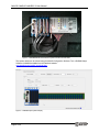
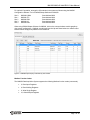
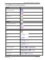
MAQ 20 ® Industrial Data Acquisition and Control System MA1039 MAQ20 LabVIEW VI User Manual MA1039 MAQ®20 LabVIEW VI User Manual MAQ20 LabVIEW VI User Manual MA1039 Rev. A – April 2015 © 2015 Dataforth Corporation. All Rights Reserved. ISO9001:2008-Registered QMS The information in this manual has been checked carefully and is believed to be accurate; however, Dataforth assumes no responsibility for possible inaccuracies or omissions. Specifications are subject to change without notice. The information, tables, diagrams, and photographs contained herein are the property of Dataforth Corporation. No part of this manual may be reproduced or distributed by any means, electronic, mechanical, or otherwise, for any purpose other than the purchaser’s personal use, without the express written consent of Dataforth Corporation. MAQ®20 is a registered trademark of Dataforth Corporation ReDAQ® is a registered trademark of Dataforth Corporation Modbus® is a registered trademark of the Modbus Organization, Inc. LabVIEW™ is a trademark of National Instruments Corporation ii MA1039 MAQ®20 LabVIEW VI User Manual Table of Contents 1.0 System Features ............................................................................................................................. 1 2.0 System Description and Documentation ........................................................................................... 2 3.0 General Description ......................................................................................................................... 3 4.0 System Communications ................................................................................................................. 3 4.1 Modbus TCP............................................................................................................................ 3 5.0 MAQ20 Demonstration System and Addressing Overview ............................................................... 5 6.0 LabVIEW Tools use in the VI Development ...................................................................................... 9 7.0 MAQ20 Communications Module Interface .................................................................................... 12 8.0 MAQ20 Thermocouple Input Module Interface ............................................................................... 13 9.0 MAQ20 Millivolt, Voltage & Current Input Module Interface............................................................. 15 10.0 MAQ20 Voltage & Current Output Module Interface ....................................................................... 18 11.0 MAQ20 Discrete Input & Output Module Interface .......................................................................... 20 12.0 Reading and Writing Data with the MAQ20 LabVIEW VI ................................................................ 22 13.0 Operating the MAQ20 Process Simulator with the MAQ20 LabVIEW VI ......................................... 24 13.1 Read Ambient Temperature .................................................................................................... 24 13.2 Control the VOUT1 LED Bar ................................................................................................... 24 13.3 Read VOUT2 LED Bar Control Monitor ................................................................................... 24 13.4 Control TC Heat 1 and TC Heat 2 ........................................................................................... 25 13.5 Read Bat Toggle Switch Position ............................................................................................ 26 13.6 Control Motor Pot 1 and Motor Pot 2 ....................................................................................... 26 14.0 LabVIEW VI File ............................................................................................................................ 27 15.0 References .................................................................................................................................... 27 iii MA1039 MAQ®20 LabVIEW VI User Manual About Dataforth Corporation Our passion at Dataforth Corporation is designing, manufacturing, and marketing the best possible signal conditioning, data acquisition, and data communication products. Our mission is to set new standards of product quality, performance, and customer service. Dataforth Corporation, with more than a quarter century of experience, is the worldwide leader in Instrument Class® Industrial Electronics – rugged, high performance signal conditioning, data acquisition, and data communication products that play a vital role in maintaining the integrity of industrial automation, data acquisition, and quality assurance systems. Our products directly connect to most industrial sensors and protect valuable measurement and control signals and equipment from the dangerous and degrading effects of noise, transient power surges, internal ground loops, and other hazards present in industrial environments. Dataforth spans the globe with more than 50 International Distributors and US Representative Companies. Our customers benefit from a team of over 130 sales people highly trained in the application of precision products for industrial markets. In addition, we have a team of application engineers in our Tucson factory ready to solve any in-depth application questions. Upon receipt of an RFQ or order, our Customer Service Department provides fast one-day delivery information turnaround. We maintain an ample inventory that allows small quantity orders to be shipped from stock. Dataforth operates under an ISO9001:2008 quality management system. Contacting Dataforth Corporation Contact Method E-Mail: Technical Support Website: Phone: Fax: Mail: Contact Information [email protected] www.dataforth.com 520-741-1404 and toll free 800-444-7644 520-741-0762 Dataforth Corporation 3331 E. Hemisphere Loop Tucson, AZ 85706 USA Errata Sheets Refer to the Technical Support area of Dataforth’s website (www.dataforth.com) for any errata information on this product. iv MA1039 MAQ®20 LabVIEW VI User Manual 1.0 System Features The MAQ20 Data Acquisition System encompasses more than 25 years of design excellence in the process control industry. It is a family of high performance, DIN rail mounted, programmable, multichannel, industrially rugged signal conditioning I/O and communications modules. Instrument Class Performance ±0.035% Accuracy Industry leading ±0.3C CJC Accuracy over full operating temperature range Ultra low Zero and Span Tempco Over-range on one channel does not affect other channels 1500Vrms Channel-to-Bus Isolation 240Vrms Continuous Field I/O Protection ANSI/IEEE C37.90.1 Transient Protection Ventilated Communications and I/O Modules Industrial Operating Temperature of -40°C to +85°C Wide Range 7-34VDC Power CE Compliant, UL/CUL Listing and ATEX Compliance pending Industry Leading Functionality The system is a Modbus Server and can be operated remotely with no local PC Up to 4GB of logged data can be transferred via FTP during real-time acquisition Up to 24 I/O modules, or 384 channels, per system, per 19” rack width Per-channel configurable for range, alarms, and other functions Backbone mounts within DIN rail and distributes power and communications System firmware automatically registers the installation and removal of I/O modules I/O modules can be mounted remotely from the Communications Module Equal load sharing power supply modules allow for system expansion Hot Swappable I/O modules with Field-side pluggable terminal blocks on most models Sophisticated package enables high density mounting in 3U increments DIN Rail can be mounted on a continuous flat panel or plate Distributed Processing Enables Even More Functionality Output modules are programmable for user-defined waveforms Discrete I/O modules have seven high level functions: Pulse Counter Frequency Counter Waveform Measurement Time Between Events Frequency Generator PWM Generator One-Shot Pulse Generator Multiple Software Options Free Configuration Software Intuitive Graphical Control Software ReDAQ Shape Graphical HMI Design & Runtime Solution IPEmotion Muli-Vendor and Multi-Language Solution Programming examples and LabVIEW VIs OPC Server Page 1 of 30 MA1039 MAQ®20 LabVIEW VI User Manual 2.0 System Description and Documentation A MAQ20 Data Acquisition System must have as a minimum a Communications Module, a Backbone, and one I/O Module. Examples include: MAQ20-COMx Communications Module with Ethernet, USB and RS-232 or RS-485 Interface MAQ20-DIOx Discrete Input / Output Module MAQ20-xTC Type x Thermocouple Input Module MAQ20-mVxN, -VxN Voltage Input Module MAQ20-IxN Process Current Input Module MAQ20-IO, -VO Process Current Output and Process Voltage Output Module MAQ20-BKPLx x Channel System Backbone Refer to www.dataforth.com/maq20.aspx for a complete listing of available modules and accessories. System power is connected to the Communications Module, which in turn powers the I/O modules. For systems with power supply requirements exceeding what the Communications Module can provide, the MAQ20-PWR3 Power Supply module is used to provide additional power. When a MAQ20 I/O module is inserted into a system, module registration occurs automatically, data acquisition starts, and data is stored locally in the module. The system is based on a Modbus compatible memory map for easy access to acquired data, configuration settings and alarm limits. Information is stored in consistent locations from module to module for ease of use and system design. MAQ20 modules are designed for installation in Class I, Division 2 hazardous locations and have a high level of immunity to environmental noise commonly present in heavy industrial environments. MAQ20 communications modules provide connection between a host computer and a MAQ20 Data Acquisition System over Ethernet, USB, RS-485 or RS-232. Ethernet communications use the Modbus TCP protocol, USB communications are based on the Modbus RTU protocol, and RS-485 and RS-232 communications use the Modbus RTU protocol. Serial communications over RS-485 can be either 2-wire or 4-wire. Each MAQ20-COMx module can interface to up to 24 MAQ20 I/O modules in any combination allowing high channel counts and great flexibility in system configuration. A removable microSD card can be used by the MAQ20-COMx module to log data acquired from the MAQ20 I/O modules. For details on hardware installation, configuration, and system operation, refer to the manuals and software available for download from www.dataforth.com/maq20_download.aspx This includes, but is not limited to: MA1036 MA1040 MA1041 MA1037 MA1038 MAQ20 Quick Start Guide MAQ20 Communications Module Hardware User Manual MAQ20 milliVolt, Volt and Current Input Module Hardware User Manual MAQ20 Configuration Software Tool User Manual MAQ20 ReDAQ Shape for MAQ20 User Manual MAQ20-940/-941 ReDAQ Shape Software for MAQ20 – Developer Version/User Version MAQ20-945 MAQ20 Configuration Software Tool MAQ20-952 IPEMotion Software for MAQ20 Page 2 of 30 MA1039 MAQ®20 LabVIEW VI User Manual 3.0 General Description The MAQ20 LabVIEW VIs provide a common interface to the MAQ20 Data Acquisition System usable by any SCADA, HMI or other application developed using LabVIEW. This simplifies communication with the MAQ20 and allows quick development of application specific, sophisticated data acquisition and control systems. The VIs were developed using LabVIEW 2014 and use the standard National Instruments Modbus VIs. They are building blocks that show how to connect to a MAQ20 system and perform I/O module configuration and data input and output operations. Dataforth provides the MAQ20DEMO-B Demonstration Suitcase and Process Simulator to show basic operation of the system. The MAQ20 system in this demonstration set is comprised of: MAQ20-COM4 MAQ20-JTC MAQ20-VDN MAQ20-VO MAQ20-DIOL Communications Module 8-Channel J-Type Thermocouple Input Module 8-Channel Differential Voltage Input Module 8 Isolated Channel Voltage Output Module 5 Discrete Output / 5 Discrete Input Module The VI titled MAQ20 IO Module Interface TCP Example shows how to interface to each of these modules and is developed specifically to connect to the Demonstration Suitcase. The techniques used are examples of how to interface to any MAQ20 Communications or I/O module and portions of the VI can be cut and pasted to develop other applications. 4.0 System Communications The MAQ20 uses the Modbus TCP protocol for communication over Ethernet and the Modbus RTU protocol for communication over USB, RS-485 and RS-232. Refer to MA1040 MAQ20 Communications Module Hardware User Manual found at www.dataforth.com/maq20_download.aspx for detailed information on communications setup. VIs are set up for communication over Ethernet. Serial communications are set up in a similar manner using the Modbus Serial Master VI. The Modbus TCP Master and Close VIs provide the basic communications interface. Figure 1: Modbus TCP VIs 4.1 Modbus TCP The standard method of Ethernet connection to the MAQ20 is to use a static IP address. The factory default is: MAQ20 factory default static IP address: 192.168.128.100 Page 3 of 30 MA1039 MAQ®20 LabVIEW VI User Manual If desired, the IP address can be changed using the MAQ20 Configuration Software Tool or ReDAQ Shape Software for MAQ20. Configure the Ethernet port on the host computer to also use a static IP address. In Windows 7, this is done by choosing Control Panel > Network and Sharing Center. Next select Change Adapter Settings, select the network adapter to be used for the Channel and select Properties, then select TCP/IPv4 and Properties. Figure 2: Host Computer Ethernet Port Configuration Configure the port to use a static IP address. Host computer static IP Address: 192.168.xxx.xxx Choose any address that does not match the one set in the MAQ20. If the MAQ20 is set for 192.168.128.100, set the host computer to a lower address such as 192.168.128.095 for faster response. Host computer Subnet Mask: Page 4 of 30 255.255.0.0 MA1039 MAQ®20 LabVIEW VI User Manual Figure 3: Host Computer IP Address & Subnet Mask 5.0 MAQ20 Demonstration System and Addressing Overview The MAQ20 Data Acquisition System uses an automated registration process which periodically scans the system and will detect when MAQ20 I/O modules are added and removed. Each module is assigned an address space of 2000 addresses based on the Registration Number and starting at address 2000. I/O module with Registration Number 1 is assigned address space 2000 – 3999, I/O module with Registration Number 2 is assigned address space 4000 – 5999 and so on. The starting address for the module is very important because this is the offset address that must be added to the addresses listed in the I/O module address map to know where data for that module is located within the system level address map. The MAQ20-COMx Communication Module is always assigned a Registration Number of 0. Channel data for the MAQ20 Input and Output modules is stored starting at address 1000 within each module register space. Address Maps for each module are found at the end of the individual MAQ20 I/O and Communication module hardware user manuals. A few of these are listed below. MA1040 MA1041 MA1042 MA1043 MA1044 MA1045 MA1046 MA1047 MA1048 MAQ20 Communications Module Hardware User Manual MAQ20 milliVolt, Volt and Current Input Module Hardware User Manual MAQ20 Voltage & Current Output Module Hardware User Manual MAQ20-DIOL Discrete IO Module Hardware User Manual MAQ20 RTD-Potentiometer Input Module Hardware User Manual MAQ20-PWR3 Load-Share Power Supply Hardware User Manual MAQ20 Strain Gage Input Module Hardware User Manual MAQ20 TC Input Module Hardware User Manual MAQ20 Frequency Input Module Hardware User Manual The MAQ20 IO Module Interface TCP Example VI is set up to interface to the MAQ20DEMO-B demonstration hardware. This system is comprised of a MAQ20-COM4 communications module and 4 I/O modules which connect to a Process Simulator to allow user input and output and give visual feedback. Page 5 of 30 MA1039 MAQ®20 LabVIEW VI User Manual Figure 4: MAQ20DEMO-B Demonstration System with Process Simulator The system details can be viewed using the MAQ20 Configuration Software Tool or ReDAQ Shape Software for MAQ20 available from the Dataforth website, www.dataforth.com/maq20_download.aspx. Figure 5: ReDAQ Shape System Display Page 6 of 30 MA1039 MAQ®20 LabVIEW VI User Manual For optimal VI operation, arrange the I/O modules in the system as follows using the MAQ20 Configuration Software Tool or ReDAQ Shape Software for MAQ20. Slot 0 Slot 1 Slot 2 Slot 3 Slot 4 MAQ20-COM4 MAQ20-JTC MAQ20-VDN MAQ20-VO MAQ20-DIOL Start Address 0000 Start Address 2000 Start Address 4000 Start Address 6000 Start Address 8000 When using ReDAQ Shape Software for MAQ20, click on the communications module graphic to view system configuration. Highlight a module and use the Up and Down buttons to make the Slot Number match the physical position on the backbone. Figure 6: ReDAQ Shape Display of Modules by Slot Number Modbus Function Codes The MAQ20 Data Acquisition System supports the following Modbus function codes (commands): 3, Read Input Registers 4, Read Holding Registers 6, Write Single Register 16, Write Multiple Registers Page 7 of 30 MA1039 MAQ®20 LabVIEW VI User Manual Modbus Addresses The system makes no distinction between Modbus Input registers and Modbus Holding registers. Read Input Registers will return the same data as Read Holding Registers as long as both commands use the same address and quantity. Modbus addresses are 0-based, meaning the first address is 0x0000 (0) and the last is 0xFFFF (65535). Address values map directly to address fields of all Modbus commands. Although only a small percentage of available Modbus addresses are mapped to data and/or control functions, the system allows access to the entire range of Modbus addresses. If a Read command accesses an address that the system does not map, 0x0000 will be returned. If a Write command accesses an address that the system does not map, the write will have no effect. Modbus Exceptions The system will return the following Modbus exception codes under the given conditions: 1, Illegal Function: The received function code is unknown or not supported. 2, Illegal Address: The received address and quantity would access data beyond address 0xFFFF. 3, Illegal Data: The number of bytes in the request does not match that expected or one or more fields of the command contains an invalid value (i.e., a quantity field is zero or too large, a byte count field is zero or does not agree with the quantity field, etc.). 6, Server Busy: This exception only occurs with Modbus TCP and indicates that the MAQ20 Data Acquisition System is already processing its maximum number of simultaneous transactions and cannot accept more. The request should be re-issued after a response is received from one of the four active transactions. Page 8 of 30 MA1039 MAQ®20 LabVIEW VI User Manual 6.0 LabVIEW Tools use in the VI Development Controls Numeric Unsigned 16-bit String Double Precision Stop Indicators Numeric Unsigned 16-bit Array String Functions Wait Multiply Divide Add Subtract To Unsigned Byte Integer Byte Array to String To Word Integer Page 9 of 30 MA1039 MAQ®20 LabVIEW VI User Manual Functions Index Array Build Array Constants Numeric Unsigned 16-bit Integer Numeric Array Double Precision VIs New TCP Master Read Holding Registers Write Multiple Holding Registers Close Modbus Master Structures While Loop Page 10 of 30 MA1039 MAQ®20 LabVIEW VI User Manual Structures For Loop Case Structure Page 11 of 30 MA1039 MAQ®20 LabVIEW VI User Manual 7.0 MAQ20 Communications Module Interface One Read Holding Registers VI is used to read the module Model #, and a second is used to read the registers containing the data for the Real Time Clock. Slot # is multiplied by 2000 to generate the address offset. Figure 7: MAQ20-COM2 or –COM4 Basic VI Structure To determine the address to read from, use the Address Map for the MAQ20-COM2 and MAQ20COM4 modules found in the appendix of MA1040 MAQ20 Communications Module Hardware User Manual. An excerpt from the Address Map is shown below. Real Time Clock data is stored starting at address 1200. NOTE: When a module is registered in a system, addresses are offset by 2000 * R, where R is the Registration Number. Start Address 1200 1201 1202 1203 1204 1205 1206 Read/ Write R/W R/W R/W R/W R/W R/W R/W Address Range 1200 - 1299 : Module RTC and Temperature Number of Contents Description Data Range Registers 1 Second 0-59 0-59 1 Minute 0-59 0-59 1 Hour 0-23 0-23 1 Day (1-7), 1 = Sunday 1 to 7 1 Date (1-31) 1 to 31 1 Month (1-12) 1 to 12 1 Year (0-99) 0 to 99 The MAQ20-COM4 module in the demonstration system has a registration number of 0 and an address offset of 2000 * 0 = 0. The addresses to read from are 0 (address offset) + 1200 (RTC seconds) = 1200, through 0 (address offset) + 1206 (RTC year) = 1206. Figure 8: MAQ20-COM2 or –COM4 VI User Interface Page 12 of 30 Data type INT16 INT16 INT16 INT16 INT16 INT16 INT16 MA1039 MAQ®20 LabVIEW VI User Manual 8.0 MAQ20 Thermocouple Input Module Interface One Read Holding Registers VI is used to read the module Model #, and a second is used to read the registers containing the data from the input channels. Slot # is multiplied by 2000 to generate the address offset. Figure 9: MAQ20-JTC Basic VI Structure To determine the address to read from, use the Address Map for the MAQ20-xTC Types J, K, T, R and S Thermocouple Input Modules found in the appendix of MA1047 MAQ20 TC Input Module Hardware User Manual. An excerpt from the Address Map is shown below. Channel Data is stored starting at address 1000. NOTE: When a module is registered in a system, addresses are offset by 2000 * R, where R is the Registration Number. Start Read/ Address Write R/W 1000 Address Range 1000 - 1699 : Module Data Number of Contents Description Registers 8 Channel Data Data for all 8 Channels Data Range See Table Data type INT16 The MAQ20-JTC module in the demonstration system has a registration number of 1 and an address offset of 2000 * 1 = 2000. The addresses to read from are 2000 (address offset) + 1000 (MAQ20-JTC Ch 0) = 3000 through 2000 (address offset) + 1007 (MAQ20-JTC Ch 7) = 3007. MAQ20 input module input ranges can be configured on a per-channel basis. These can be set or checked using the MAQ20 Configuration Software Tool or ReDAQ Shape Software for MAQ20 to obtain the optimum range and resolution for given measurements. The following screen shot is from the ReDAQ Shape for MAQ20 software. Figure 10: ReDAQ Shape Interface to MAQ20-JTC Page 13 of 30 MA1039 MAQ®20 LabVIEW VI User Manual Data stored in the MAQ20 registers is in counts. To convert this to engineering units, use the count mapping tables in the appendix of the specific MAQ20 Hardware User Manual. Table 1: MAQ20-JTC Range Assignment JTC Range 0 1 2 Standard Input Temperature -100°C to +760°C (Default) -100°C to +393°C -100°C to +199°C Equivalent Counts Over/Under Range Equivalent Counts Deg C per Count -539 to 4095 -102°C to +775°C -550 to 4177 0.1855 -1078 to 4236 -2156 to 4290 -102°C to +401°C -102°C to +203°C -1100 to 4321 -2199 to 4376 0.0928 0.0464 The VI does not have the ability to configure the input ranges, but this could be added to the VI by adding a Write Multiple Holding Registers VI and writing to the appropriate registers. To display the data read from the module in engineering units, the user must select the input range for each channel to match the actual module configuration. Count mapping for the MAQ20-JTC module has been built into the VI. Range and count mapping are applied to the measured data and then the resulting measured temperature is displayed. Figure 11: Converting MAQ20-JTC Data to Engineering Units Page 14 of 30 MA1039 MAQ®20 LabVIEW VI User Manual Figure 12: MAQ20-JTC VI User Interface 9.0 MAQ20 Millivolt, Voltage & Current Input Module Interface One Read Holding Registers VI is used to read the module Model #, and a second is used to read the registers containing the data from the input channels. Slot # is multiplied by 2000 to generate the address offset. Figure 13: MAQ20-VDN Basic VI Structure To determine the address to read from, use the Address Map for the MAQ20-MVDN, -VDN, -VSN, -IDN or –ISN Input Modules found in the appendix of MA1041 MAQ20 mV-V-mA Input Module Hardware User Manual. An excerpt from the MAQ20-VDN Address Map is shown below. Channel Data is stored starting at address 1000. NOTE: When a module is registered in a system, addresses are offset by 2000 * R, where R is the Registration Number. Address Range 1000 - 1699 : Module Data Start Read/ Number of Address Write Registers 1000 R 16 Contents Channel Data Description Data for all 8 Channels Data Range -4096 to 4095 Data type INT16 The MAQ20-VDN module in the demonstration system has a registration number of 2 and an address offset of 2000 * 2 = 4000. The addresses to read from are 4000 (address offset) + 1000 (MAQ20-VDN Ch 0) = 5000 through 4000 (address offset) + 1005 (MAQ20-VDN Ch 5) = 5005. MAQ20 input module input ranges can be configured on a per-channel basis. These can be set or checked using the MAQ20 Configuration Software Tool or ReDAQ Shape Software for MAQ20 to obtain the optimum range and resolution for given measurements. The following screen shot is from the ReDAQ Shape for MAQ20 software. Page 15 of 30 MA1039 MAQ®20 LabVIEW VI User Manual Figure 14: ReDAQ Shape Interface to MAQ20-VDN Data stored in the MAQ20 registers is in counts. To convert this to engineering units, use the count mapping tables in the appendix of the specific MAQ20 Hardware User Manual. MAQ20-VDN Table 2: MAQ20-VDN Range Assignment Range 0 1 2 3 4 Standard Input Voltage -60V to +60V -40V to +40V -20V to +20V -10V to +10V -5V to +5V (Default) Equivalent Counts -4016 to 4016 -4016 to 4016 -4016 to 4016 -4016 to 4016 -4016 to 4016 Over/Under Range -61.2V to +61.2V -40.8V to +40.8V -20.4V to +20.4V -10.2V to +10.2V -5.1V to +5.1V Equivalent Counts -4096 to 4095 -4096 to 4095 -4096 to 4095 -4096 to 4095 -4096 to 4095 Volts per Count 0.01494 0.009961 0.004980 0.002490 0.001245 The VI does not have the ability to configure the input ranges, but this could be added to the VI by adding a Write Multiple Holding Registers VI and writing to the appropriate registers. To display the data read from the module in engineering units, the user must select the input range for each channel to match the actual module configuration. Count mapping for the MAQ20-VDN module has been built into the VI. Range and count mapping are applied to the measured data and then the resulting measured voltage is displayed. Page 16 of 30 MA1039 MAQ®20 LabVIEW VI User Manual Figure 15: Converting MAQ20-VDN Data to Engineering Units Figure 16: MAQ20-VDN VI User Interface Page 17 of 30 MA1039 MAQ®20 LabVIEW VI User Manual 10.0 MAQ20 Voltage & Current Output Module Interface A Read Holding Registers VI is used to read the module Model #. Slot # is multiplied by 2000 to generate the address offset. Figure 17: MAQ20-VO Basic VI Structure To determine the address to write to, use the Address Map for the MAQ20-VO or -IO Output Modules found in the appendix of MA1042 MAQ20 Voltage & Current Output Module Hardware User Manual. An excerpt from the MAQ20-VO Address Map is shown below. Channel Data is stored starting at address 1000. NOTE: When a module is registered in a system, addresses are offset by 2000 * R, where R is the Registration Number. Address Range 1000 - 1699 : Module Data Start Address R/W Number of Registers 1000 R/W 8 Contents Channel Data Description Data Range Data type Data for each of 8 channels Default = 2048 See Table INT16 The addresses to write to are 6000 (address offset) + 1000 (MAQ20-VO Ch 0) = 7000 through 6000 (address offset) + 1007 (MAQ20-VO Ch 7) = 7007. MAQ20 output module output ranges can be configured on a per-channel basis. These can be set or checked using the MAQ20 Configuration Software Tool or ReDAQ Shape Software for MAQ20 to obtain the optimum range and resolution for given control signals. The following screen shot is from the ReDAQ Shape for MAQ20 software. Figure 18: ReDAQ Shape Interface to MAQ20-VO Page 18 of 30 MA1039 MAQ®20 LabVIEW VI User Manual Data stored in the MAQ20 registers is in counts. To convert this to engineering units, use the count mapping tables in the appendix of the specific MAQ20 Hardware User Manual. Table 3: MAQ20-VO Range Assignment Range 0 1 2 3 4 5 Standard Output Voltage -10V to +10V (Default) -5V to +5V -2.5V to +2.5V 0 to +10V 0 to +5V 0 to +2.5V Equivalent Counts 98 to 3998 1073 to 3023 1561 to 2536 2048 to 3998 2048 to 3023 2048 to 2536 Over/Under Range -10.5V to +10.5V -5.25V to +5.25V -2.625V to +2.625V 0 to +10.5V 0 to +5.25V 0 to +2.625V Equivalent Counts 0 to 4095 1024 to 3072 1536 to 2560 2048 to 4095 2048 to 3072 2048 to 2560 Volts per Count 0.005128 0.005128 0.005128 0.005128 0.005128 0.005128 The VI does not have the ability to configure the output ranges, but this could be added to the VI by adding a Write Multiple Holding Registers VI and writing to the appropriate registers. To enter data to be written to the module in engineering units, count mapping for the MAQ20-VO module has been built into the VI. Range and count mapping are applied to the data to be written and then the resulting signal representation in counts is sent to the module. Figure 19: Entering MAQ20-VO Data in Engineering Units Page 19 of 30 MA1039 MAQ®20 LabVIEW VI User Manual Figure 20: MAQ20-VO VI User Interface 11.0 MAQ20 Discrete Input & Output Module Interface A Read Holding Registers VI is used to read the module Model #. Slot # is multiplied by 2000 to generate the address offset. Figure 21: MAQ20-DIOL Basic VI Structure To determine the addresses to read from and write to, use the Address Map for the MAQ20-DIOL Discrete I/O Module found in the appendix of MA1043 MAQ20-DIOL Discrete IO Module Hardware User Manual. An excerpt from the MAQ20-DIOL Address Map is shown below. Channel Data is stored starting at address 1000. NOTE: When a module is registered in a system, addresses are offset by 2000 * R, where R is the Registration Number. Address Range 1000 - 1299 : Module Data and Special Function Selection Start Read/ Number of Contents Description Data Range Address Write Registers Example: Starting at address 1009 DO0 – DO4 and decreasing to address Inverted Logic 1000, 0 = switch closed DIO States, Binary MSB to LSB DI4 to DI0 and 1 = switch open Representation, DO4 to DO0 = Inverted Logic 1011011000. 1000 R/W 10 DI0 – DI4 Data written to an input Inverted Logic Addr 1000 = LSB channel will be ignored. 0 = input > Addr 1009 =MSB Data written to an output threshold channel committed to a 1 = input < Special Function returns an threshold error. Default = 1 for all channels. Page 20 of 30 Data type INT16 MA1039 MAQ®20 LabVIEW VI User Manual The MAQ20-DIOL module in the demonstration system has a registration number of 4 and an address offset of 2000 * 4 = 8000. The addresses to write to are: 8000 (address offset) + 1000 (MAQ20-DIOL Ch DO0) = 9000 through 8000 (address offset) + 1004 (MAQ20-DIOL Ch DO4) = 9004 and the addresses to read from are: 8000 (address offset) + 1005 (MAQ20-DIOL Ch DI0) = 9005 through 8000 (address offset) + 1009 (MAQ20-DIOL Ch DI3) = 9009 Although the data is Boolean, the MAQ20 stores it as INT16 and uses holding register R/W operations for access. Figure 22: Reading and Writing Discrete I/O Data From and To MAQ20-DIOL Figure 23: MAQ20-DIOL VI User Interface Page 21 of 30 MA1039 MAQ®20 LabVIEW VI User Manual 12.0 Reading and Writing Data with the MAQ20 LabVIEW VI The complete VI allows read/write operations to MAQ20 modules in up to 5 slots, or a MAQ20 data acquisition system comprised of one Communications Module and 4 I/O Modules. Figure 24: MAQ20 VI User Interface The number of read interval, number of slots to scan, slot displayed, and the number of registers to read are all selectable by the user. This VI has a user interface optimized for the following system configuration: Slot 0 Slot 1 Slot 2 Slot 3 Slot 4 Page 22 of 30 MAQ20-COM4 MAQ20-JTC MAQ20-VDN MAQ20-VO MAQ20-DIOL MA1039 MAQ®20 LabVIEW VI User Manual It will interface to other modules placed in these slots. The interface to each type of MAQ20 module has been built into a Case Structure, and this is embedded in a For Loop, so each module is scanned sequentially and continuously. Figure 25: MAQ20 Basic VI Structure Page 23 of 30 MA1039 MAQ®20 LabVIEW VI User Manual 13.0 Operating the MAQ20 Process Simulator with the MAQ20 LabVIEW VI The I/O channels presented in this manual are interrelated on the MAQ20DEMO-B Demonstration Suitcase and Process Simulator, so the following exercises can be performed once the system has been configured as outlined in the previous sections. 13.1 Read Ambient Temperature On the demonstration system, the MAQ20-JTC module Ch 7 measures the thermocouple protruding from the Process Simulator. Run the VI and observe the ambient temperature read on Channel 7. Touch the thermocouple protruding from the Process Simulator and observe the temperature change. Figure 26: Reading Ambient Temperature using MAQ20-JTC 13.2 Control the VOUT1 LED Bar On the demonstration system, the orange LED bar display is controlled by MAQ20-VO Ch 0. Run the VI and enter MAQ20-VO Ch 0 values between -10V and +10V. Observe the voltage change in the VOUT1 LED bar display. Figure 27: Process Simulator VOUT1 LED Bar Control 13.3 Read VOUT2 LED Bar Control Monitor On the demonstration system, MAQ20-VDN module Ch 0 measures a 0 to 3V signal for the green LED bar display, labeled VOUT2. The green LED bar display is controlled by Motor Pot 1 when MAQ20-VO Ch 1 is set to -10V and it is controlled by MAQ20-VO Ch 2 when MAQ20-VO Ch 1 is set to +10V. Run the VI and set MAQ20-VO Ch 1 to -10V. Rotate Motor Pot 1 and observe the voltage change on MAQ20-VDN Ch 0 and the change in the green LED bar display. Set MAQ20-VO Ch 1 to +10V. Enter MAQ20-VO Ch 2 values between -10V and +10V and observe the voltage change on MAQ20-VDN Ch 0 and the change in the VOUT2 LED bar display. Page 24 of 30 MA1039 MAQ®20 LabVIEW VI User Manual Figure 28: Process Simulator VOUT2 LED Bar Control and Monitor 13.4 Control TC Heat 1 and TC Heat 2 On the demonstration system, the MAQ20-JTC module Ch 6 measures the signal from a simulated heated thermocouple. TC Heat 1 control is driven by MAQ20-VO Ch 4 and TC Heat 2 control is driven by MAQ20-VO Ch 5. MAQ20-VDN module Ch 5 measure the 0 to +3V TC Heat 1 control signal and MAQ20-VDN module Ch 6 measure the 0 to +3V TC Heat 2 control signal. Run the VI and set MAQ20-VO Ch 4 and Ch 5 to values between 0V and +10V. The intensity of the TC Heat indicators represent the magnitude of the heater control voltages. Observe the simulated temperature change on MAQ20-JTC Ch 6 and observe the heat control voltages on MAQ20-VDN Ch 5 and Ch 6. Figure 29: Process Simulator Heated TC Control and Monitor Page 25 of 30 MA1039 MAQ®20 LabVIEW VI User Manual 13.5 Read Bat Toggle Switch Position On the demonstration system, MAQ20-DIOL module input channels DI0 through DI4 are connected to bat toggle switches SW1 through SW5 respectively. The discrete input channels read logic 1 for the bat toggle switch in the left position and the LED off and logic 0 for the bat toggle switch in the right position and the LED on. Run the VI. Operate switches SW1 – SW5 on the Process Simulator and observe the state change on Discrete Input Ch 0 – Ch 4. Figure 30: Process Simulator Bat Toggle Monitor 13.6 Control Motor Pot 1 and Motor Pot 2 On the demonstration system, MAQ20-DIOL module output channels DO1 and DO2 are connected to Motor Pot 1 FWD and REV controls respectively and output channels DO3 and DO4 are connected to Motor Pot 2 FWD and REV controls respectively. MAQ20-VDN module Ch 0 measures a 0 to 3V signal for the green LED bar display, labeled VOUT2 and MAQ20-VDN module Ch 2 measures a 0 to 3V signal for the blue LED bar display, labeled VOUT3. The green LED bar display is controlled by Motor Pot 1 when MAQ20-VO Ch 1 is set to -10V and the blue LED bar display is controlled by Motor Pot 2 when MAQ20-VO Ch 1 is set to -10V. Run the VI and set MAQ20-VO Ch 4 to -10V. Change the value of channel DO1 to turn on or off forward motion (clockwise) or the value of channel DO2 to turn on or off reverse motion (counterclockwise) for Motor Pot 1. Observe the voltage change on MAQ20-VDN Ch 0 and the change in the green LED bar display. Change the value of channel DO3 to turn on or off forward motion (clockwise) or the value of channel DO4 to turn on or off reverse motion (counter-clockwise) for Motor Pot 2. Observe the voltage change on MAQ20-VDN Ch 2 and the change in the blue LED bar display. The Motor Pot controls have the following truth-table: Page 26 of 30 Channel DO1 0 1 0 1 Channel DO2 0 0 1 1 Motor Pot Rotation None CW CCW None Channel DO3 0 1 0 1 Channel DO4 0 0 1 1 Motor Pot Rotation None CW CCW None MA1039 MAQ®20 LabVIEW VI User Manual 14.0 LabVIEW VI File The VI was created in LabVIEW 2014 and does not require any special toolkits to run. It is titled MAQ20 IO Module Interface TCP Example.vi, and is available for download from the Software Download Center at www.dataforth.com/maq20_download.aspx 15.0 References Dataforth MAQ20 Software Download Center MAQ20 Configuration Software Tool ReDAQ Shape Software for MAQ20 MAQ20 Hardware and Software User Manuals National Instruments, LabVIEW www.ni.com/getting-started/labview-basics/ Page 27 of 30 MA1039 MAQ®20 LabVIEW VI User Manual DATAFORTH WARRANTY Applying to Products Sold by Dataforth Corporation a. General. Dataforth Corporation (“Dataforth”) warrants that its products furnished under this Agreement will, at the time of delivery, be free from defects in material and workmanship and will conform to Dataforth's applicable specifications or, if appropriate, to buyer's specifications accepted in writing by Dataforth. DATAFORTH'S OBLIGATION OR LIABILITY TO BUYER FOR PRODUCTS WHICH DO NOT CONFORM TO THE ABOVE STATED WARRANTY SHALL BE LIMITED TO DATAFORTH, AT DATAFORTH'S SOLE DISCRETION, EITHER REPAIRING, REPLACING, OR REFUNDING THE PURCHASE PRICE OF THE DEFECTIVE PRODUCT(S) PROVIDED THAT WRITTEN NOTICE OF SAID DEFECT IS RECEIVED BY DATAFORTH WITHIN THE TIME PERIODS SET FORTH BELOW: i. for all software products including licensed programs, thirty (30) days from date of initial delivery; or governmental agency of any country resulting directly or indirectly (i) from any acts not authorized by Dataforth in writing or any statements regarding the products inconsistent with Dataforth's product documentation or standard warranty, or (ii) from any breach or threatened breach by buyer, or by any of its employees or agents, of any term, condition or provision of this Warranty or (iii) from any warranty, representation, covenant or obligation given by buyer to any third party and not expressly provided for in this Warranty or (iv) for any non-compliance (in any form) of the products with any necessary or mandatory applicable laws, regulations, procedures, government or industry policies or requirements related to the use, sale or importation of the products. Such indemnification shall include the payment of all reasonable attorneys' fees and other costs incurred by Dataforth in defending such claim. c. ii. for all hardware products including complete systems, one (1) year from date of initial delivery; iii. for all special products, sixty (60) days from date of initial delivery; and further, all products warranted hereunder for which Dataforth has received timely notice of nonconformance must be returned FOB to Dataforth's plant in Tucson, Arizona USA within thirty (30) days after the expiration of the warranty periods set forth above. The foregoing warranties shall not apply to any products which Dataforth determines have, by buyer or otherwise, been subjected to operating and/or environmental conditions in excess of the maximum value established therefore in the applicable specifications, or any products that have been the subject of mishandling, misuse, misapplication, neglect, improper testing, repair, alteration or damage. THE PROVISIONS OF THE FOREGOING WARRANTIES EXTEND TO BUYER ONLY AND NOT TO BUYER'S CUSTOMERS OR USERS OF BUYER'S PRODUCTS. THE DATAFORTH STANDARD WARRANTY IS IN LIEU OF ALL WARRANTIES OF MERCHANTABILITY AND FITNESS FOR A PARTICULAR PURPOSE OR USE AND ALL OTHER WARRANTIES WHETHER EXPRESS, IMPLIED OR STATUTORY, EXCEPT AS TO TITLE. THE DATAFORTH STANDARD WARRANTY MAY BE CHANGED BY DATAFORTH WITHOUT NOTICE. b. Buyer Indemnity. Buyer agrees to indemnify and hold Dataforth harmless from and against any and all claims, damages and liabilities whatsoever asserted by any person, entity, industry organization, government, Page 28 of 30 Limitation on Damages. (1) IN NO EVENT SHALL DATAFORTH, ITS SUPPLIERS, LICENSORS, SERVICE PROVIDERS, EMPLOYEES, AGENTS, OFFICERS, AND DIRECTORS BE LIABLE FOR INDIRECT, SPECIAL, INCIDENTAL, COVER, ECONOMIC, PUNITIVE, ACTUAL, EXEMPLARY, CONSEQUENTIAL OR OTHER DAMAGES OF ANY NATURE INCLUDING, WITHOUT LIMITATION, LOST PROFITS OR REVENUES, COSTS OF REPLACEMENT PRODUCTS, LOSS OR DAMAGE TO DATA ARISING OUT OF THE USE OR INABILITY TO USE ANY DATAFORTH PRODUCT. (2) IN NO EVENT SHALL DATAFORTH BE LIABLE FOR DIRECT, SPECIAL, INDIRECT, INCIDENTAL OR CONSEQUENTIAL DAMAGES OF ANY NATURE RESULTING FROM BUYER’S NONCOMPLIANCE (IN ANY FORM) WITH ALL NECESSARY OR MANDATORY APPLICABLE LAWS, REGULATIONS, PROCEDURES, GOVERNMENT POLICIES OR REQUIREMENTS RELATED TO THE USE, SALE OR IMPORTATION OF PRODUCTS. (3) IN NO EVENT WILL THE COLLECTIVE LIABILITY OF DATAFORTH AND ITS SUPPLIERS, LICENSORS, SERVICE PROVIDERS, EMPLOYEES, AGENTS, OFFICERS, AND DIRECTORS TO ANY PARTY (REGARDLESS OF THE FORM OF ACTION, WHETHER BASED UPON WARRANTY, CONTRACT, TORT, OR OTHERWISE) EXCEED THE GREATER OF EITHER US$1000.00 (ONE THOUSAND DOLLARS U.S.A. CURRENCY) OR THE AMOUNT PAID TO DATAFORTH FOR THE APPLICABLE PRODUCT OR SERVICE OUT OF WHICH LIABILITY AROSE. MA1039 MAQ®20 LabVIEW VI User Manual (4) DATAFORTH’S LIABILITY ARISING OUT OF THE PRODUCTION, SALE OR SUPPLY OF PRODUCTS OR THEIR USE OR DISPOSITION, WHETHER BASED UPON WARRANTY, CONTRACT, TORT OR OTHERWISE, SHALL NOT EXCEED THE GREATER OF EITHER US$1000.00 (ONE THOUSAND DOLLARS U.S.A. CURRENCY) OR THE ACTUAL PURCHASE PRICE PAID BY BUYER FOR DATAFORTH'S PRODUCTS. DATAFORTH'S LIABILITY FOR ANY CLAIM OF ANY KIND SHALL IN NO CASE EXCEED THE OBLIGATION OR LIABILITY SPECIFIED IN THIS WARRANTY. d. Technical Assistance. Dataforth 's Warranty as hereinabove set forth shall not be enlarged, diminished or affected by, and no obligation or liability shall arise or grow out of, Dataforth's rendering of technical advice, facilities or service in connection with buyer's order of the products furnished hereunder. e. Warranty Procedures. Buyer shall notify Dataforth of any products which it believes to be defective during the applicable warranty period and which are covered by the Warranty set forth above. Buyer shall not return any products for any reason without the prior authorization of Dataforth and issuance of a Return Material Authorization ("RMA") number. After issuance of a RMA number, such products shall be promptly returned by buyer (and in no event later than thirty (30) days after the Warranty expiration date), transportation and insurance prepaid, to Dataforth's designated facility for examination and testing. Dataforth shall either repair or replace any such products found to be so defective and promptly return such products to buyer, transportation and insurance prepaid. Should Dataforth's examination and testing not disclose any defect covered by the foregoing Warranty, Dataforth shall so advise buyer and dispose of or return the products in accordance with buyer's instructions and at buyer's sole expense, and buyer shall reimburse Dataforth for testing expenses incurred at Dataforth's then current repair rates. f. Repair Warranty. Dataforth warrants its repair work and/or replacement parts for a period of ninety (90) days from receipt by buyer of the repaired or replaced products or for the remainder of the warranty period for the initial delivery of such order as set forth in paragraph a above, whichever is greater. g. Critical Applications. Certain applications using Dataforth's products may involve potential risks of death, personal injury, or severe property or environmental damage ("Critical Applications"). DATAFORTH'S PRODUCTS ARE NOT DESIGNED, INTENDED, AUTHORIZED, OR WARRANTED TO BE SUITABLE FOR USE IN LIFE-SUPPORT DEVICES OR SYSTEMS, SAFETY EQUIPMENT, NUCLEAR FACILITY APPLICATIONS OR OTHER CRITICAL APPLICATIONS WHERE MALFUNCTION OF THE PRODUCT CAN BE EXPECTED TO RESULT IN PERSONAL INJURY, DEATH OR SEVERE PROPERTY DAMAGE. BUYER USES OR SELLS SUCH PRODUCTS FOR USE IN SUCH CRITICAL APPLICATIONS AT BUYER'S OWN RISK AND AGREES TO DEFEND, INDEMNIFY AND HOLD HARMLESS DATAFORTH FROM ANY AND ALL DAMAGES, CLAIMS, PROCEEDINGS, SUITS OR EXPENSE RESULTING FROM SUCH USE. h. Static Sensitive. Dataforth ships all product in anti-static packages. Dataforth's Warranty as hereinabove set forth shall not cover warranty repair, replacement, or refund on product or devices damaged by static due to buyer's failure to properly ground. _____________________________________________________________________________________________ Page 29 of 30 MA1039 MAQ®20 LabVIEW VI User Manual Application Support Dataforth provides timely, high-quality product support. Call 1-800-444-7644 TOLL-FREE. Returns/Repair Policy All warranty and repair requests should be directed to the Dataforth Customer Service Department at (520) 741-1404. If a product return is required, request a Return Material Authorization (RMA) number. You should be ready to provide the following information: 1. Complete product model number. 2. Product serial number. 3. Name, address, and telephone number of person returning product. 4. Special repair instructions. 5. Purchase order number for out-of-warranty repairs. The product should be carefully packaged, making sure the RMA number appears on the outside of the package, and ship prepaid to: Dataforth Corporation 3331 E. Hemisphere Loop Tucson, AZ 85706 USA An RMA Request Form and instructions for processing are also found at www.dataforth.com. The information provided herein is believed to be reliable; however, DATAFORTH assumes no responsibility for inaccuracies or omissions. DATAFORTH assumes no responsibility for the use of this information, and all use of such information shall be entirely at the user's own risk. Application information is intended as suggestions for possible use of the products and not as explicit performance in a specific application. Prices and specifications are subject to change without notice. No patent rights or licenses to any of the circuits described herein are implied or granted to any third party. DATAFORTH does not authorize or warrant any DATAFORTH product for use in life support devices and/or systems. MAQ20 LabVIEW VI User Manual MA1039 Rev. A – April 2015 © 2015 Dataforth Corporation. All Rights Reserved. ISO9001:2008-Registered QMS Page 30 of 30