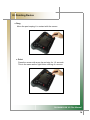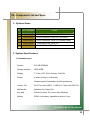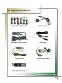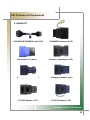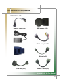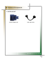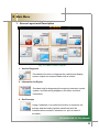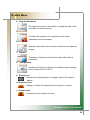
1
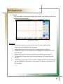
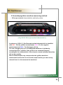
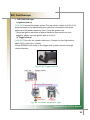
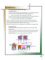
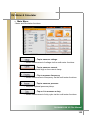
CARMANSCAN
VG Plus Manual
Ver. 080601
1
CONTENT
SAFETY
I.
Mainframe Parts and Functions
1.
2.
3.
4.
5.
II.
Front of Mainframe……..…………………………………………...7
Right Side of Mainframe …..………………………………………9
Left Side of Mainframe .…………………………………………..10
Top of Mainframe..…………………………………………………11
Back of Mainframe..……………………………………………….12
Status Display LED
1. Descriptions ............................................................................13
III.
Pointing Device
1. About the Touch Panel…………………………………………..14
2. How to Use a Touch Panel………………………………………15
IV.
Battery
1. Charging the Battery..……………………………………………17
2. Use of Battery...........................................................................18
3. Check of Remaining Battery Power.......................................18
4. Cautions in Handling...............................................................19
V.
External Display Device
1. Connection………………………………………………………...20
2. How to Connect ..………………………………………………...20
VI.
Power Supply..………………………………………………….21
VII. Component List and Spec.
1. Components
1) Basic Items.……………………………………………………..22
2) Asian Kit...………………………………………………………23
CARMANSCAN VG Plus Manual
2
CONTENT
3) European Kit……………………………………………………24
4) Australian Kit…………………………………………………..24
2. Option Items.………………………………………………………25
3. System Specifications
1) Hardware Spec. ……………………………………………...25
2) Protocol Spec…..………………………………………………26
3) Scope & Meter Spec..…………………………………………26
VIII. Pictures of Components
1.
2.
3.
4.
IX.
Basic Kit…………………………………………………………….27
Asian Kit …………………………………………………………....29
European Kit.............................................................................31
Australian Kit …...……………………………………………… 32
Main Menu
1. Screen Layout and Description………………………………..33
X.
Vehicle Diagnosis Program
1. Connection to Vehicle & Selection of Diagnosis Program..35
2. Diagnosis Program..……………………………………………..42
XI.
Maintenance Information
1.
2.
3.
4.
Main Menu…………………………………………………………58
Help per Part………………………………………………………59
Help per Trouble Type...…………………………………………63
Vehicle Wiring Diagrams………………………………………..66
XII. Saved Data
1.
2.
3.
4.
Main Menu…………………………………………………………67
Saved Data in Fault Diagnosis Function …………………….68
Oscilloscope Saved Data….……………………………………69
Screen Capture Data…………………………………………….70
CARMANSCAN VG Plus Manual
3
CONTENT
XIII. Internet
1. Internet Connection……………………………………………...71
2. Internet Screen...………………………………………………....73
XIV. Oscilloscope
1.
2.
3.
4.
5.
6.
7.
Connecting to a Vehicle………………………………………….74
Main Menu……………………….………………………………....76
Auto Measurement.…………….…………………………………77
Manual Measurement…….….………………………………......78
Secondary Ignition Waveform Measuring Method………….94
Ignition Waveform Measurement.…..………………………...101
Comparison of Normal Waveform & Misfire Waveform…..108
XV. Meter & Simulator
1. Main Menu………………………………………………………...109
XVI. Utility Box
1.
2.
3.
4.
Main Menu...............................................................................111
Calculator …………………………..…………………………….112
Touch Screen Calibration ………….………………………….113
File Explorer ……………………………………………………..114
XVII. Program Download
1.
2.
3.
4.
5.
6.
Main Menu………………………………………………………...115
Delete………………………………………………………………116
Download……………………………….………………………...118
Hard Disk Information …………….……………………………121
Internal Information ………………….…………………………121
Select File List ……………………….………………………….122
CARMANSCAN VG Plus Manual
4
CONTENT
XVIII. Configuration Setting
1. Main Menu……………………………………………………….....123
XIX. Printer Setting…………………………………………125
XX.
NGA 6000……………………………………………….128
CARMANSCAN VG Plus Manual
5
Cautions in Use
Safety Instruction
Cautions in Use
The CARMAN SCAN VG Plus described in this manual was manufactured for those
who have the basic knowledge required for its use.
Users should follow the safety instructions described in this manual for safe and
efficient use of the product.
The cautions in use are as follows:
Do not drop the product.
Never use the product without the rubber boot in place.
Do not put the product on a distributor or high-tension cables.
Even though CARMAN SCAN VG Plus is manufactured to
Internally prevent the interference from the
Electromagnetic waves, the strong interference by excessive
Electromagnetic waves may damage the product.
The strong surge or electric shock applied to the power cable
may damage the power supply unit of the product. So, do not
use the product while the power supply is unstable.
The voltage rating of the AC/DC adaptor is 12V DC.
Be sure to use an AC/DC adaptor with the rated voltage.
The allowed power input to the oscilloscope is 0 - 500V DC.
Do not apply the out-of-range voltage to the input port of an
oscilloscope.
CARMANSCAN VG Plus Manual
6
I. Mainframe Parts and Functions
1. Front of Mainframe
Fig. 1-1: Front view of Mainframe
1. Status display LED
☞ Displays the status of the product.
2. Direction Key
☞ When selecting menu items, use these keys to move up, down, left and
right. (The functions of the keys on the right hand side can be changed with
those of the direction keys on the left hand side (10) via menus.)
3. Enter / Esc
☞ With these keys, you can start, cancel, quit, or move one-step backward of
a program.
CARMANSCAN VG Plus Manual
7
I. Mainframe Parts and Functions
4. HELP
☞ Pressing the HELP button for any function, displays the relevant
Description is in detail.
5 / 7. Speaker
☞ Outputs the sound from the product.
Note! )
When you play sound with the built-in speaker, it may produce a splitting
sound if you raise the volume.
6. Special Function Keys (F1 ~ F6)
☞ Used to run application programs or special functions.
8. Power Button
☞ Used to turn the power of the mainframe on and off.
TIPS)
If you press this button for three or more seconds while the power is on, power
is turned off.
9. O / X
☞ Provides a YES or NO function when removing trouble codes or starting
an actuator.
10. Direction Keys
☞ Provides Pg UP /Pg Down / HOME / END function.
(You can change the functions of these keys with those of the direction keys
on the right hand side (2) via menus).
11. LCD
☞ Displays the screen of the product.
CARMANSCAN VG Plus includes a touch panel on the top of the LCD.
CARMANSCAN VG Plus Manual
8
I. Mainframe’s Parts and Functions
2. Right Side of Mainframe
Fig. I-2 Right Side of Mainframe
1. Headphone Port
☞ Headphone connecting port.
(Supports a mini plug with a diameter 3.5mm.)
This port may not support some shapes, so check it before purchasing one.
CARMANSCAN VG Plus Manual
9
I. Mainframe’s Parts and Functions
3. Left Side of Mainframe
Fig. I-3 Left Side of Mainframe
1. External Display Device Connector (VGA)
☞ Used for connection to external display devices such as CRT monitor, etc.
2. Keyboard Connector
☞ Used for connection to a keyboard.
3. LAN Connector
☞ Used for connection to LAN cable.
CARMANSCAN VG Plus Manual
10
I. Mainframe’s Parts and Functions
4. Top of Mainframe
Fig. I-4 Top of Mainframe
1. Power Connector
☞ A connector for connection to AC adaptor or vehicle battery.
2. RS 232 Connector
☞ A connector for connection to RS 232 cable.
3. DLC Communication Cable Connector
☞ A connector for connection to the DLC comm. cable for vehicle diagnosis.
4 / 5. USB Port
☞ Connector for connection to peripherals such as a printer or mouse which
supports USB connection.
CARMANSCAN VG Plus’s USB connector supports both USB 2.0 and 1.1.
Note! )
When using the USB device not connected to external power source, the
maximum power consumption per port is 500mA.
For the details, see the manual of a USB device.
When connecting two or more PC cards or USB devices at the same time,
use AC adaptor. Using a battery will weaken the power of the battery.
CARMANSCAN VG Plus Manual
11
I. Mainframe Parts and Functions
5. Back of Mainframe
Fig. I-5 Back of Mainframe
1. Pen for Touch Panel
☞ A pen for touch panel is placed here.
Be sure to put it back here after using it to prevent loss.
2. Support
☞The support makes it easy to put the product on a working table for
convenient use.
3. Built-in Battery Pack
☞ A built-in battery pack is included.
4. Vent Hole
☞ Discharges the heat generated inside of the product.
If you turn on the power, the internal cooling fan rotates to discharge the heat.
CARMANSCAN VG Plus Manual
12
II. Status Display LED
Fig. II-1 LED Window
1. Descriptions
1. POWER Lamp
☞ Will be lit when the power from AC adaptor is used.
2. BATTERY Lamp
☞ Will be lit when the power from the built-in battery is used.
3. LAN Lamp
☞ Will be lit when the product is connected to another computer or Internet via
a LAN Cable.
4. HDD (Hard disk) Lamp
☞ Will be lit when the built-in hard disk is used.
TIPS)
Do not press the power button while HDD lamp is lit, as it may damage the
hard disk.
5. DLC Lamp
☞ Will be lit when the product is communicating with a vehicle via DLC cable.
6. TRIGGER
☞ Will be lit when a scope function is used or a trigger-specified wave-form is
displayed.
CARMANSCAN VG Plus Manual
13
III. Pointing Device
1. About the Touch Panel
A touch panel is a convenient pointing device on a screen, in which you can
manipulate a mouse pointer directly.
You can operate the electro-magnetic induction touch panel attached to the LCD of
the CARMANSCAN VG Plus by using the attached pen. Since you can manipulate
it on the screen directly, faster operation is possible.
POINT)
▶
If the pressing force of the pen tip is not sufficient, the unit may not recognize
the manipulation. So, use the pen applying appropriate and sufficient force.
▶
Manipulate the touch panel only with the attached pen.
▶
Do not touch the panel with a sharp object, as it may damage the touch panel
or LCD.
CARMANSCAN VG Plus Manual
14
III. Pointing Device
2. How to use a Touch Panel
● Tap
Press the screen once with a pen.
This is the same as a single left button click of a mouse.
● Double Tap
Press the screen twice consecutively and swiftly.
This is the same as double-clicking a mouse.
CARMANSCAN VG Plus Manual
15
III. Pointing Device
● Drag
Move the pen keeping it in contact with the screen.
● Point
Press the screen with a pen tip and stay for 1-2 seconds.
This is the same as the right button clicking of a mouse.
CARMANSCAN VG Plus Manual
16
IV. Battery
1. Charging the Battery
1) Connect AC adaptor.
- Charging is started, and if the unit is switched on, the battery icon’s scale on
the main screen. (It is not necessary to switch the CARMANSCAN VG Plus
on for charging).
2) Check the charged amount below the battery icon on the screen.
3) Disconnect the AC adaptor.
POINT)
▶
The battery charging time of CARMANSCAN VG Plus is about 12 hours,
however, it will vary depending on the usage situation.
▶
For the newly purchased battery or a battery which has not been
charged for one or more months, charge it fully first before use.
▶
If the surrounding temperature is too low or high, the battery charging
capacity is decreased.
▶
If you charge a battery immediately after using it, the battery may not be
charged due to the activation of the battery protection function resulting
from high battery temperature. In this case, wait for a while until the battery
temperature is lowered.
CARMANSCAN VG Plus Manual
17
IV. Battery
2. Use of Battery
This section describes how to use the battery of the CARMANSCAN VG Plus.
1) Disconnect AC adaptor and press the power button.
POINT)
▶ If the surrounding temperature is low, the battery operation time is
shortened.
▶ The operation time of a fully charged new CARMANSCAN VG Plus
battery is about 1 – 2 hours, however, it varies depending on the usage
situation.
▶ If the battery temperature increases, the operation of the product may
become slow. In this case, connect AC adaptor.
3. Check of Remaining Battery Power
If the product is powered on, you can check the remaining battery power
level displayed under the battery icon on the right top of a screen.
POINT)
▶
Due to the characteristics of a lithium ion battery, the actual remaining
battery level may differ from what is displayed on the screen due to the
usage environment (e.g., the number of charges and discharges).
CARMANSCAN VG Plus Manual
18
IV. Battery
4. Cautions in Handling
● The Battery is a very sensitive product. Do not give strong impact to it
when installing or removing it. For safety reasons, do not use a battery
pack, which has been severely shocked.
- A severely shocked battery may cause an electric shock or a rupture.
●
Do not disassemble it.
- If you touch the inside of a battery after breaking it down, it may cause an
electric shock or a fire.
●
Discharging
- A charged battery discharges power little by little even if you do not use it.
So, it is recommended to charge it right before using it.
-
●
If you do not use a battery for a long time (e.g., I or months), remove and
store it in a cool place.
About the lifetime
- If you do not use the mainframe for a long time, this may consume the
battery and weaken its power.
-
Use the mainframe at least once a month and check the battery status.
-
Since a battery is a consumable product, using it for a long time may
decrease its charging capacity. In this case, replace it with a new one.
-
If the battery operation time is excessively short, it means that the battery
life time has come to an end.
-
Remove the used-up battery from the mainframe. Otherwise, it may cause
an electric shock or a fire.
Leaving a battery in a high-temperature place may consume the battery and
weaken its power.
●
Disposition
- When disposing a battery, put an insulation tape over the battery connector
and take other necessary actions to prevent disconnection.
●
Battery operation time
- The surrounding temperature affects the operation time of a battery. If the
temperature is low, the operation time may be shortened.
CARMANSCAN VG Plus Manual
19
V. External Display Device
1. Connection
You can connect external display devices such as a projector, CRT or LCD display
to CARMAN SCAN VG Plus.
When connecting or disconnecting an external display device,
first turn off the mainframe power and disconnect the AC
adaptor. Otherwise, it may cause an electric shock.
2. How to Connect
1. Turn off the power of the mainframe, and disconnect AC adaptor.
2. Connect the cable of the display device to the external display device
connector on the left side of the mainframe. See [Fig. I-3: Left Side of
Mainframe].
3. Connect the power cable of CRT/LCD display, and turn on the power.
4. Connect AC adaptor to the mainframe, and turn the power on.
CARMANSCAN VG Plus Manual
20
VI. Power Supply
CARMANSCAN VG Plus can be refilled by the following ways:
1. Cigar Lighter Cable
The cigar lighter cable can supply power to the product.
However, when the vehicle ignition switch is off or upon starting a vehicle,
power is not supplied to the cigar lighter socket.
2. Vehicle Battery
Connect the red clip of the battery connection cable to the (+) battery
terminal, and black clip to the (-) terminal. Connect the cigar lighter power cable
between the power extention cable and the product.
In this case, power is supplied anytime regardless of the ignition switch
status or vehicle starting.
Be careful when connecting the cable, as incorrect polarity
may damage the mainframe.
3. DLC Main Cable
Where the vehicle satisfies the OBD-II communication convention and uses
a 16-pin diagnostic connector, the DLC main cable can supply power to the
product directly without a separate power supply.
4. Battery
The built-in battery can run the product for 1-2 hours without separate
power supply.
TIPS)
The battery operation duration may vary depending on the usage and
environment.
5. AC/DC Adapter
If AC/DC adapter is used as a power supply, the battery may be charged
automatically, and it may be used as the power source of the mainframe.
CARMANSCAN VG Plus Manual
21
VII. Component List and Spec.
1. Components
1) Basic Kit
NO. PART NUMBER
ITEMS
1
11000-11000
MAINBODY
2
11000-11100
RUBBER SHROUD
3
11000-11110
CARRYING CASE
4
11000-11111
OPERATION MANUAL
5
11000-11113
Program CD (*2EA)
6
11000-11210
DLC MAIN CABLE (16P)
7
11000-11220
CIGAR LIGHT POWER CABLE
8
11000-11230
POWER EXTENTION CABLE
9
11000-11240
SCOPE CABLE (4CHANNEL)
10
11000-11250
RS-232C CABLE
11
11000-11260
SECONDARY IGNITION PICK UP
12
11000-11270
USB CABLE
13
11000-11280
Trigger PICK UP
14
11000-11290
AC/DC POWER ADAPTER
15
11000-11300
RECHAGEABLE BATTERY SET
CARMANSCAN VG Plus Manual
22
VII. Component List and Spec.
2) Asian Kit
NO. PART NUMBER
ITEMS
1
11000-21100
HYUNDAI / MITSUBISHI CABLE (12P)
2
11000-21210
KIA / MAZDA ADAPTER (6+1PIN)
3
11000-21220
KIA ADAPTER 20P (BLUE)
4
11000-21300
DAEWOO / GM ADAPTER (12P)
5
11000-21410
SSANGYONG ADAPTER (14P)
6
11000-21420
SSANGYONG ADPTER (20P)
7
11000-21510
TOYOTA ADAPTER (17R)
8
11000-21520
TOYOTA ADAPTER (17C)
9
11000-21600
SAMSUNG / NISSAN ADAPTER (14P)
10
11000-21700
HONDA ADAPTER (3P)
11
11000-21800
HONDA ADAPTER (5P)
12
11000-21820
MAZDA “C” ADAPTER (17P)
13
11000-21910
SUBARU ADAPTER (9P)
14
11000-21310
MITSUBISHI CABLE (12+16)
CARMANSCAN VG Plus Manual
23
VII. Component List and Spec.
3) European Kit
NO. PART NUMBER
ITEMS
1
11000-31000
AUDI / VW CABLE (2+2P)
2
11000-32000
BMW ADAPTER (20P)
3
11000-33100
BENZ 38PIN BOARD
4
11000-33200
BENZ CABLE (3 LINER)
5
11000-33300
OPEL ADAPTER (10PIN)
6
11000-34000
PSA CABLE (2PIN)
7
11000-34100
PSA CABLE (30PIN)
8
11000-34200
RANAULT CABLE (12PIN)
4) Australian Kit
NO. PART NUMBER
ITEMS
1
11000-21810
HOLDEN CABLE (6PIN)
2
11000-21300
FORD CABLE (20PIN)
CARMANSCAN VG Plus Manual
24
VII. Component List and Spec.
2. Optional Items
NO. PART NUMBER
ITEMS
1
11000-51000
PRESSURE VACUUM PICK UP
2
11000-52000
HIGH CURRENT PICK UP (1A~600A)
3
11000-53000
LOW CURRENT PICK UP (500mA~100A)
4
11000-54000
TEMPERATURE PICK UP
5
11000-55000
DLI IGNITION PICK UP
3. System Specifications
1) Hardware spec.
-
System
: 512 MB DDRAM
-
Storage medium
: HDD 80GB
-
Display
: 7" Color LCD, Touch Screen, VGA Out
-
Scope
: 4-channel scope, multi-meter
Measurement of secondary ignition waveforms
-
Comm. Port
: DLC Port, Host USB 1.1, USB 2.0, Client LAN, RS-232
-
Multimedia
: Speaker Out, Video Out
-
Key pad
: 4 Direction keys, 6 Function keys (Bottom)
-
Battery
: PCM Li-ion battery, operable for about 1 hour
CARMANSCAN VG Plus Manual
25
VII. Component List and Spec.
2) Protocol Spec.
•
•
•
•
•
•
•
J1850 (VPW, PWM)
KWP2000
ISO 9141-2
CAN, J1587
Hi-speed serial
SW CAN
CCD
3) Scope & Meter Spec.
3)-1 Scope Spec.
•
4-channel digital scope
•
Voltage measurement range: ±500V
•
Trigger function (Mode/Source/Level/Delay)
•
Ground level adjustment function
•
Waveform storage function
•
Zoom function
3)-2 Meter Spec.
•
4-channel multi-meter
•
Voltage measurement: ±500VDC
•
Frequency measurement: 0 ~200 KHz
•
Duty measurement: 0 ~ 100 %
•
Resistance measurement: 0 ~ 10 ㏁
Temperature measurement: -20 ~ 150℃
Pressure measurement: Vacuum – 100psi,
Pressure – 200 Kpa
Auto Unit Conversion
Current measurement: High Current 600A
Low Current 100A Auto Unit Conversion
•
•
•
CARMANSCAN VG Plus Manual
26
VIII. Pictures of Components
1. Basic Kit
MainBody
Operation Manual
DLC Main cable(16p)
Carrying Case
Program CD (*2ea)
Cigar Light Power Cable
Power Extention Cable
CARMANSCAN VG Plus Manual
27
VIII. Pictures of Components
Scope Cable (4Channel)
RS232C Cable
Secondary ignition pickup
USB Cable
Trigger pickup
AC/DC Power adaptor
Rechargeable battery Set
CARMANSCAN VG Plus Manual
28
VIII. Pictures of Components
2. ASIAN KIT
HYUNDAI/ MITSUBISHI cable (12P)
KIA adapter 20P (Blue)
KIA/MAZDA adapter (6+1P)
Daewoo / GM adapter (12P)
Ssangyong adapter (14P)
Ssangyong adapter (20P)
TOYOTA adapter (17C)
TOYOTA adapter (17R)
CARMANSCAN VG Plus Manual
29
VIII. Pictures of Components
Ssangsung /NISSAN adapter (14P)
HONDA adapter (5P)
SUBARU adapter (9P)
HONDA adapter (3P))
MAZDA “C” adapter (17P)
Mitsubishi Cable (12+16P)
CARMANSCAN VG Plus Manual
30
VIII. Pictures of Components
3. EUROPEAN KIT
Audi/VW cable (2+2P)
BMW adapter (20P)
BENZ 38pin board
BENZ cable (3 LINER)
Opel adaptor (10P)
PSA cable(2P)
PSA cable(30P)
RANAULT cable(12P)
CARMANSCAN VG Plus Manual
31
VIII. Pictures of Components
4. AUSTALIAN KIT
Holden Adaptor (6P)
Ford Cable (20P)
CARMANSCAN VG Plus Manual
32
IX. Main Menu
1. Screen Layout and Description
Fig. IX-1 Main Screen Layout
1. Vehicle Diagnosis
: Provides the function to diagnose the vehicle and display
sensor outputs via communication with a vehicle.
2. Information for Repair
: Provides help for diagnosing the engine’s electronic control
system. Includes wiring diagrams, and other technical
information.
3. Oscilloscope
: Using 4 channels, it provides the function to measure the
primary and secondary ignition waveforms and the
waveformsfrom sensors, actuators etc. plus a meter &
simulator
CARMANSCAN VG Plus Manual
33
IX. Main Menu
4. Program Download
: Provides the function to download or upload the data on the
hard disk or internal memory.
5. Utilities
: Provides the functions of a calculator, touch screen
calibration and a file browser.
6. Save Data
: Displays saved data from sensors, waveforms and captured
images.
7. Internet
: Provides an Internet search function while LAN cable is
connected.
8. Configuration
: Provides the function to change or modify the basic settings
of the Carman Scan VG Plus.
9. Battery Icon
☞ Shows the remaining power or charged state of the internal
battery.
10. Keyboard Icon
☞ Displays or hides the keyboard for text input on a screen.
11. Capture Icon
☞ Provides a screen capture function.
CARMANSCAN VG Plus Manual
34
IX.Vehicle
Main Menu
X.
Diagnosis Program
1. Connection to Vehicle & Selection of Diagnosis Program
1) Connecting to Vehicle
1. Connect the main cable to the DLC connector on the top of the
-
-
CARMANSCAN VG Plus mainframe.
Push in the levers on the both sides of the connector until you hear a click
sound.
Fig. X-1 Connecting to DLC Connector
2. Make a connection after checking the diagnostic connector’s
position and specifications of the vehicle to be diagnosed.
Abnormal connection may cause defective communication.
Fig. X-2 Connecting to Vehicle Side Connector
CARMANSCAN VG Plus Manual
CARMANSCAN VG Manual
35
X. Vehicle Diagnosis Program
2) Selecting a Diagnosis Program
1. On the main menu, tap on the vehicle diagnosis program item.
Fig. X-3 Main Menu
-
2. Tap on the vehicle maker’s country, and maker item to
diagnose.
If you select the area icon on the left, the maker pane is activated.
Fig. X-4 Main Screen of Diagnosis Program
CARMANSCAN VG Plus Manual
36
X. Vehicle Diagnosis Program
Fig. X-5 Diag Language
If the diagnostic program in VG Plus flash memory contains more than
one language, VG Plus allows you to choose other languages for
diagnosis.
CARMANSCAN VG Plus Manual
37
X. Vehicle Diagnosis Program
Tap on the vehicle system item (engine, auto transmission, ABS, Air-bag,
etc.) to be diagnosed.
Fig. X-6 Diagnosis Program
3. After “Connecting to ECM…” is displayed, and then the communication
will become active.
Fig. X-7 Communication Screen
TIPS)
When the communication is successful, [X-12 Diagnosis Main Screen]
appears, but if it fails, a “Communication Error” message is displayed.
If an error message is displayed, check if the diagnostic cable was
connected properly, and if you selected the correct vehicle type, model
year, and system spec., and then try again.
CARMANSCAN VG Plus Manual
38
차량 진단
프로그램Program
X. Vehicle
Diagnosis
: Tap on the desired item to search or analyze the
saved data.
-
Select a file name on the left pane to activate the right pane, and check the
saved information (e.g., vehicle type, saved date, number of saved items).
Fig. X-8 Saved Data List Screen
: Tap on “GRAPH” to check the saved data.
☞ You can check the saved data with this function.
☞ See Fig. X-9 Graph Screen
: Tap on “DEL” to delete a file.
☞ You can delete the selected data.
: Tap on “RENAME” to change a file name.
: Tap on “EXIT” to exit this menu.
CARMANSCAN VG Plus Manual
CARMANSCAN VG Manual
39
차량 진단
프로그램Program
X. Vehicle
Diagnosis
Fig. X-9 Graph Screen
: Tap on “LIST” to return to the saved data list menu.
☞ Then, Fig. X-8 Saved Data List Screen is displayed.
: Tap on “VIEW CH +” to increase the number of the
signals displayed on a single screen.
☞ The default number is 4.
☞ The number can be increased up to 8.
: Tap on “VIEW CH -” to decrease the number of the
signals displayed on a single screen.
: Tap on “UP” to move up to the upper items to be
displayed on the screen.
: Tap on “DOWN” to move down to the lower items to be
displayed on the screen.
CARMANSCAN VG Plus Manual
CARMANSCAN VG Manual
40
차량 진단
프로그램Program
X. Vehicle
Diagnosis
: Tap on “DLC LOCATION” to check the location of
the ECU connector on the vehicle side.
-
TIP) This icon is activated only when you select the production region
and a maker of the vehicle to diagnose. See Fig. X-5
You can check the diagnostic connector’s location of a vehicle as follows.
Fig. X-10: Diagnosis Connector Location-1 Screen
Fig. X-11: Diagnosis Connector Location-2 Screen
CARMANSCAN VG Plus Manual
CARMANSCAN VG Manual
41
X. Vehicle Diagnosis Program
2. Diagnosis Program
1) Main Screen
[
-
Fig. X-12: Diagnosis Main Screen
1. Procedure for selecting a diagnosis menu
Shows the procedure for selecting a diagnosis menu.
Country -> Maker -> Vehicle Type -> System -> System Spec.
2. Icon for returning to a main screen
: Pressing this icon on any menu displays the main menu again.
-
Fig. X-3 Main Menu
3. Trouble Code (Press F1 button or tap “DTC” on the screen)
You can display the trouble code of the system, and delete the trouble code.
-
4. Sensor (Press F2 button or tap “SENSOR” on the screen)
You can search the current values of the sensors of the relevant system.
CARMANSCAN VG Plus Manual
42
X. Vehicle Diagnosis Program
5. Actuator (Press F3 button or tap “ACTUATOR” on the screen)
- You can check if the system is normal by forcibly starting or stopping the
actuators of the relevant system.
6. Other (Press F4 button or tap “ OTHER” on the screen)
- You can check the system spec and use various supplementary functions.
The actual functions will depend on the vehicle selected
7. DIAG Menu (Press F5 button or tap “ DIAG MENU” on the screen)
- Pressing this menu displays the diagnosis main screen again on any
screen. Fig. X-12: Diagnosis Main Screen
8. Home (exit from diagnosis) (Press F6 button or tap “HOME” on the
screen)
- Pressing this menu displays the system selection screen again on any
screen. Fig. X-6 Diagnosis Program
9. You can also operate the function on any menu by tapping on the
screen directly.
CARMANSCAN VG Plus Manual
43
X. Vehicle Diagnosis Program
2) Major Functions
1. Trouble Code
- If troubles are detected, the trouble code, number of trouble codes and
description displayed. If there is no trouble, “NO TROUBLE CODE” is
displayed as show in the Fig. V-9.
Fig. X-13: Trouble Diagnosis Screen
: If there is a fault code, tap on “ERASE” to delete the
code.
☞ Deletes the displayed trouble code.
Be sure to delete trouble codes only when the ignition key is
on and an engine is off.
A trouble code may not be erased, or abnormal problems may
occur if deleting codes with the engine running.
TIPS) A temporary trouble code may be erased without repairing.
However, If the fault is still valid, the code is erased
temporarily, and will then be displayed again.
: Tap on “HELP” to display the help items.
☞ You can check the help, circuit diagram and normal waveform of each
sensor item.
CARMANSCAN VG Plus Manual
44
X. Vehicle Diagnosis Program
2. SENSOR
- You can analyze the changes in the sensor or actuator values.
- Min. and Max. values can be compared.
Fig. X-14: Service Data Screen (Text view)
: Tap on “+FILE” to select the record mode or open a file.
☞ Then
and
are activated.
Fig. X-15: Text View Storage Screen
: Tap on “RECORD” to start a recording.
☞ You can save the value changes of the (fixed) items you have selected for
later analysis. Recording will continue until “RECORD” is pressed again.
: Tap on ”OPEN” to open a recorded event.
☞ You can move to a screen where you can select the saved data.
[ Fig. X-14 :
서비스데이터 화면 (TEXT VIEW)CARMANSCAN VG Plus Manual
]
45
X. Vehicle Diagnosis Program
: Tap on “+SEL ITEM” to add a sensor item on a Text
screen.
☞ When the sensor data list pane on the Screen is activated, you can select
new items or delete previously selected items.
Fig. X-16
Text View Sel ITEM Screen
: Select an item to add, and then tap on “ADD FIX”.
☞ A new item is fixed, and you can see the data changes on the graph.
: Select an item to unfix, and then tap on “UNFIX”.
☞ The selected item is released from fixing.
: Tap on “INIT MIN/MAX” to re-initiate Min/Max values.
☞ This initializes the MIN/MAX value of the sensors.
CARMANSCAN VG Plus Manual
46
X. Vehicle Diagnosis Program
: Tap on “+SIMU-SCAN”.
☞ This is for the simulation of voltage, frequency and duty while checking
the changes of the sensor data value using scope terminal.
Fig. X-17
Text View SIMU SCAN Screen
: Tap on “VOLT”.
☞ When the VOLT simulation pane on the right side is activated, you can do
the simulation using voltage.
: Tap on “FREQUENCY”.
☞ When the DUTY/FREQUENCT simulation pane on the right side is
activated, you can do the simulation using duty and frequency.
CARMANSCAN VG Plus Manual
47
X. Vehicle Diagnosis Program
Fig. X-18 Service Data Screen (Graph view)
: Tap on “TEXT VIEW” to return to the text screen.
☞ You can move to the text view screen in Fig. X-14.
: Tap on “+FILE” to select the record mode or open a file.
☞ Then
and
are activated.
: Tap on “RECORD” to start a recording.
☞ You can save the value changes of the (fixed) items you have selected for
later analysis. Recording will continue until “RECORD” is pressed again.
: Tap on ”OPEN” to open a recorded event.
☞ You can move to a screen where you can select the saved data.
CARMANSCAN VG Plus Manual
48
X. Vehicle Diagnosis Program
: Tap on “+SEL ITEM” to add a sensor item on a graph
screen.
☞ When the sensor data list pane on the right side is activated, you can
select new items or delete previously selected items.
Fig. X-19 Item Selection Screen
: Select an item to add, and then tap on “ADD FIX”.
☞ A new item is fixed, and you can see the data changes on the graph.
: Select an item to unfix, and then tap on “UNFIX”.
☞ The selected item is released from fixing.
CARMANSCAN VG Plus Manual
49
X. Vehicle Diagnosis Program
/
: Tap on “CONFIG” to change the screen settings.
☞ Icons necessary for screen settings are displayed on the right hand side.
Fig. X-20 Settings Screen 1
: Tap on “VIEW CH +” to increase the number of sensor
items to be displayed on the screen.
☞ 4 items are displayed by default.
☞ But, the number can be increased up to 8.
: Tap on “VIEW CH -” to decrease the number of sensor
items to be displayed on the screen.
☞ The number can be decreased down to 1.
: Tap on “VIEW DATA” to remove or replace the numeric
data display on the graph.
☞ Data is displayed on the graph on the center of a screen.
: Tap on “VIEW RANGE” to remove or replace the MIN/MAX
values on the graph.
☞ Min/Max data is displayed on the right hand side of a graph.
CARMANSCAN VG Plus Manual
50
X. Vehicle Diagnosis Program
: Tap on “VIEW NAME” to remove or replace the data item
names on the graph.
☞ The name is displayed on the left hand side of a graph.
TIPS)
/
/
Data is displayed on the graph by default. To remove the display data
on the screen, tap on a relevant icon once. The icon then turns to a red
color, and the data will not displayed on the screen.
: To zoom the graph displayed on the screen, in or
out, tap on the “CH” icon until the desired sensor’s
channel is displayed and then tap the “MAX+” or
“MAX-“ icon.
☞ To observe the graphical wave of a test item in more detail , you can tap
on ‘+’ or ‘-‘ icon to zoom in or out the graph.
CARMANSCAN VG Plus Manual
51
X. Vehicle Diagnosis Program
/
: Tap on “CONFIG / HOLD/RUN”.
☞ You can check the changes of the date through holding or running the
screen..
Fig. X-21 Settings Screen 2
: Tap on “HOLD/RUN”.
☞ When you tap on "HOLD", the screen will be frozen and by
tapping on "RUN" the screen will proceed again.
: Tap on “PAGE” to move the screen to backward or
forward.
☞ You can check the saved screen by pages.
: Tap on "ZOOM" to zoom in or out the screen of the data
value.
☞ Default value is set up at 60 and you can zoom in and out
by 10units.
CARMANSCAN VG Plus Manual
52
X. Vehicle Diagnosis Program
3. HELP
- Displays the help information of individual items of data.
Fig. X-19 Help Items
: Tap on “TIPS” to view the information.
☞ You can view the standard values and repair information of the selected
item.
Fig. X-20 TIPS
CARMANSCAN VG Plus Manual
53
X. Vehicle Diagnosis Program
: Tap on “WAVE” to view a sample lab scope
waveform.
☞ You can view the normal waveform of a selected item.
Fig. X-21 WAVE
: Tap on “CIRCUIT” to view the wiring diagram of a
selected item.
☞ You can view the circuit diagram of a selected item.
/
[Fig. X-22 CIRCUIT]
: Tap on “UP” or “DOWN” to move a screen
upwards or downwards.
CARMANSCAN VG Plus Manual
54
X. Vehicle Diagnosis Program
4. ACTUATOR
- You can check if an actuator is normal by forcibly starting and stopping it.
Fig. X-23
Actuator Screen
TIPS)
When you select a test item on the actuator list, the “START” and
“STOP” icon on the left hand side are activated, and DURATION, test
METHOD, and test CONDITION are displayed on the right hand side.
: Tap on “START” to start or stop an actuator forcibly.
☞ Pressing this icon starts the actuation.
: Tap on “STOP” to stop an actuator being tested.
☞ Pressing this icon stops the actuation.
CARMANSCAN VG Plus Manual
55
X. Vehicle Diagnosis Program
5. Other
- You can check various adaptive values, system reset, and system specifications
information.
Fig. X-24 OTHER Screen
Fig. X-25
Resetting Adaptive Values
: Tap on “Yes” to confirm you want to delete the
adaptive values or execute the selected command.
☞ Confirms the deletion of adaptive values or execution of a command
once more before performing it.
CARMANSCAN VG Plus Manual
56
X. Vehicle Diagnosis Program
: Tap on “No” if you do not want to delete the adaptive
values or execute the selected command.
☞ Confirms you do not want to carry out the deletion of adaptive values or
execution of a command once more before performing it.
: Tap on “ENTER” if you want to execute the command.
☞ Executes a command.
: Tap on “ESC” to quit the function.
☞ Use this icon to cancel a command or quit a function.
: Tap on the desired numbers.
☞ Use this icon to enter numbers.
: Tap on “REST” to reset the adaptive values.
☞ Resets the adaptive values or system resetting items.
CARMANSCAN VG Plus Manual
57
XI. Maintenance Information
1. Main Menu
Fig. XI-1: Maintenance Information Main Screen
: Tap on “Sorted by Parts”.
☞ You can view the help for the parts of 4 systems – Engine / Engine(LPG) /
ABS / Suspension.
: Tap on “Sorted by Troubles”.
☞ You can view the help for common faults of 4 systems – Engine /
Engine(LPG) / Auto Transmission / Suspension.
: Tap on “Vehicle Diagram”.
☞ You can view the circuit diagrams of a vehicle per maker.
CARMANSCAN VG Plus Manual
58
XI. Maintenance Information
2. Help per Part
-
You can view the help for the parts of 4 systems – Engine / Engine (LPG) /
ABS / Suspension.
Fig. XI-2 Help per Part
: Tap on “Troubles”.
☞ You can view the faults and repair methods of a selected part.
Fig. XI-3 Trouble Descriptions
CARMANSCAN VG Plus Manual
59
XI. Maintenance Information
: Tap on “Parts Photo”.
☞ You can view the picture of a selected part.
Fig. XI-4 Part Picture
: Tap on “EMS Configuration”.
☞ You can view a simple EMS diagram of a selected item.
Fig. XI-5 EMS Simple Diagram
CARMANSCAN VG Plus Manual
60
XI. Maintenance Information
: Tap on “Part Explanation”.
☞ You can view the detailed description and functions of parts.
Fig. XI-6 Part Description
: Tap on “Part Characteristics”.
☞ You can view the help regarding characteristics of a selected part.
Fig. XI-7 Part Characteristics
CARMANSCAN VG Plus Manual
61
XI. Maintenance Information
: Tap on “EMS Understanding”.
☞ You can view the help for the EMS algorithm.
Fig. XI-8 Understanding the Mechanism
: Tap on “Left Arrow”.
☞ Displays [Fig. XI-2] screen.
: Tap on “Right Arrow”.
☞ Displays the previous screen.
CARMANSCAN VG Plus Manual
62
XI. Maintenance Information
3.
-
Help per Trouble Type
You can view the help for the common faults of 4 systems – Engine /
Engine (LPG) / Auto Transmission / Suspension.
Fig. XI-9 Help per Trouble Type
: Tap on “Cause of Trouble”.
☞ Displays the help for causes of a fault.
Fig. XI-10 Cause of Problem
CARMANSCAN VG Plus Manual
63
XI. Maintenance Information
: Tap on “Related Part”.
☞ Displays the description of the parts related to the fault.
Fig. XI-11 Related Part
: Tap on “Analysis Method”.
☞ Displays the help for fault analysis methods.
Fig. XI-12 Analysis Method
CARMANSCAN VG Plus Manual
64
XI. Maintenance Information
: Tap on “Left Arrow”.
☞ Displays Fig. XI-9 screen.
: Tap on “Right Arrow”.
☞ Displays the previous screen.
CARMANSCAN VG Plus Manual
65
XI. Maintenance Information
4. Vehicle Wiring Diagram
- You can view the wiring diagrams of each system of a vehicle per maker.
Fig. XI-13 Vehicle Diagram Menu
- If you drag the screen, the position of the diagram will move accordingly.
Fig. XI-14 Vehicle Wiring Diagram
: Tap on “Left Arrow”.
☞ Displays Fig. XI-13 screen.
: Tap on “Right Arrow”.
☞ Displays the previous screen.
CARMANSCAN VG Plus Manual
66
XII. Saved Data
1. Main Menu
-
You can view the diagnosis data, oscilloscope data, screen capture files, etc
which have been saved in memory.
Fig. XII-1 Saved Data
: Tap on “SAVED DATA OF DIAGNOSIS” to search or
analyze the saved diagnosis data.
☞ Displays the files saved in the diagnosis program.
: Tap on “SAVED DATA OF OSCILLOSCOPE” to search
or analyze the saved oscilloscope waveforms.
☞ Displays the files saved in the oscilloscope function.
: Tap on “IMAGE VIEWER” to view the capture screens.
☞ Displays the capture files.
CARMANSCAN VG Plus Manual
67
XII. Saved Data
2. Saved Data in Fault Diagnosis Function
-
You can view the data saved in the fault diagnosis function.
Fig. XII-2 Saved Data in Fault Diagnosis Function
: Tap on “GRAPH” to check selected saved data file.
☞ Displays the saved data.
☞ See Fig. X-8 Graph Screen.
: Tap on “DEL” to delete selected saved data file.
☞ Deletes the selected data.
: Tap on “RENAME” to change a saved file name.
: Tap on “EXIT” to quit this menu.
CARMANSCAN VG Plus Manual
68
XII. Saved Data
3. Oscilloscope Saved Data
-
You can view the waveforms saved from the oscilloscope.
Fig. XII-3 Oscilloscope Saved Data
: Tap on “VIEW” to view the saved waveforms.
☞ Displays the saved waveforms.
: Tap on “RENAME” to change a saved file name.
☞ Changes a file name.
: Tap on “DELETE” after selecting a file name to
delete.
☞ Deletes the selected data.
CARMANSCAN VG Plus Manual
69
XII. Saved Data
4. Screen Capture Data
-
You can view the captured screen data.
Fig. XII-4 Screen Capture Data
: Tap on “SLIDE SHOW”.
☞ You can see the saved screen by capture one after the other..
: Tap on “SLIDE CONFIG”.
☞ You can set-up the showing time and frequency.
TIPS) Up to 13 files can be displayed at a time on the image list pane.
: Tap on “DELETE” after selecting a file to delete.
☞ Deletes the selected data.
: Tap on “REFRESH”.
☞ Refreshes the screen.
☞ Pressing this button when a new file is added or deleted will reflect
such change on a screen.
: Tap on “FULL SCREEN”.
☞ The IMAGE LIST pane disappears, and a captured screen is
displayed on the entire window.
CARMANSCAN VG Plus Manual
70
XIII. Internet
1. Internet Connection
1. Connect a LAN cable to the LAN port on the left side of a mainframe.
Fig. XIII-1 LAN Cable Connecting Method
TIPS)
A separate LAN cable may be required depending on the Internet
environment.
You can connect a LAN cable for an external modem where ADSL is used.
TIPS)
If you use a fixed IP, you have to enter IP address, subnet mask and
gateway value before using it.
If you use a dynamic ID like as in ADSL or VDSL, no additional setting is
required.
CARMANSCAN VG Plus Manual
71
XIII. Internet
2. CARMANSCAN VG Plus performs a network setting.
☞ Setting is done in the following way.
▶
▼
▼
▼
CARMANSCAN VG Plus Manual
72
XIII. Internet
2. Internet Screen
-
Through Internet, you can download a diagnostic program and maintenance
information, or surf the Internet.
Fig. XIII-2 Internet
CARMANSCAN VG Plus Manual
73
XIV. Oscilloscope
1. Connecting to a Vehicle
1. Connect a scope cable to CARMANSCAN VG Plus mainframe.
Fig. XIV-1 Scope Cable Connecting Method 1
▶ Align the up and down grooves of a scope cable with the protrusions of a
scope port, and then turn and fix it.
SCOPE CABLE TERMINAL
MAIN-BODY SCOPE TERMINAL
CARMANSCAN VG Plus Manual
74
XIV. Oscilloscope
2. Connect a probe to the signal line of a vehicle sensor, and connect the
ground clamps to a proper location.
Fig. XIV-2 Scope Cable Connecting Method 2
TIPS)
In general, the wiring of a vehicle sensor consists of power cable,
ground cable and signaling cable.
A signaling cable sends or receives signals via connection to the ECU.
When testing using the oscilloscope, you can identify the waveform via
this signaling cable.
CARMANSCAN VG Plus Manual
75
XIV. Oscilloscope
2. Main Menu
-
Here, you can measure vehicle sensors, actuators and ignition waveforms,
and use the automatic measurement function “per trouble type”.
Fig. XIV-3 Main Menu
: Tap on “Auto setup”.
☞ Displays the waveforms of sensors and actuators with the voltage and
time values preset in the oscilloscope
: Tap on “Manual setup”.
☞ You can use the oscilloscope function via user manipulation.
: Tap on “Ignition waveform”.
☞ Allows the measurement of Secondary ignition waveforms via preset
: Tap on “Analyze by trouble type”.
☞ Function to measure the related sensors or actuators for each trouble
type.
: Tap on “Load Wave file”.
☞ Function to display the saved waveforms.
CARMANSCAN VG Plus Manual
76
XIV. Oscilloscope
3. Automatic Measurement
-
Displays the waveform automatically when a measurement target sensor or
actuator is selected out of the 33 items.
Fig. XIV-4 Automatic Measurement
1. Sensor and Actuator items
A list of 33 items is displayed.
- You can select the item to test and its type.
2. Channel (4 channels are displayed).
- Select an item, and then select a channel to use.
3. Channel Item
- The items and channels, which were selected in the step 1 and 2, above
are displayed on the channel fields.
4. SAVE
- Pressing this icon saves the setting values and displays the scope
waveform measurement screen.
5. CANCEL
- Pressing this icon deletes all settings. You can then set the item and
channel again.
CARMANSCAN VG Plus Manual
77
XIV. Oscilloscope
4. Manual Measurement
-
You can set the voltage, time and trigger as you want.
Fig. XIV-5 Manual Measurement
: Tap on “SET VOLT”.
☞ You can set the voltage axis.
: Tap on “SET TIME”.
☞ You can set the time axis.
: Tap on “TRIGGER”.
☞ You can set the trigger.
: Tap on “STOP”.
☞ You can stop a screen, and save the measured waveform which
has been automatically recorded prior to that point. If there has not
been sufficient time to capture a full recording you will be prompted
to wait while to rest of the recording is completed.
CARMANSCAN VG Plus Manual
78
XIV. Oscilloscope
: Tap on “SCREEN”.
☞ You can change to the screen configuration mode.
: Tap on “CURSOR”.
☞ You can change to the cursor position mode.
TIPS)
Basically, the menus of the Auto Setup are the same as those of the
Manual Setup measurement screen. The difference is – in the auto
setup, a desirable voltage/time setting is preset for each item being
tested; while in the manual setup, the user may set it as desired.
CARMANSCAN VG Plus Manual
79
XIV. Oscilloscope
1. Voltage Setting
-
The vertical line on the grid displayed on the screen is the voltage axis.
The user can adjust the size of one scale from a minimum 20mV to
maximum 50V per division.
Fig. XIV-6 Voltage Setting
: Tap on “CHANNEL”.
☞ Activates channels from CH1 to CH4 in sequence.
/
: Tap on “Up” or “Down” arrows.
☞ You can adjust the voltage of a selected channel.
: Tap on “Return” Arrow.
☞ The screen returns to Fig. XIV-5 Manual Measurement screen.
CARMANSCAN VG Plus Manual
80
XIV. Oscilloscope
TIPS)
☞ Channel and voltage setting
As shown in Fig. XIV-7 Channel Setting Box, you can also activate a
relevant channel by tapping on the box assigned to each channel, and set
the voltage using Up/Down button.
☞ AC/DC setting
By tapping the AC icon shown in the Fig. XIV-7 Channel Setting Box, you
can switch from DC to AC measurements.
AC measurement is available only in CH1.
Fig. XIV-7 Channel Setting Box.
CARMANSCAN VG Plus Manual
81
XIV. Oscilloscope
2. Time Setting
- The horizontal line on the grid displayed on the screen is the time axis.
-
A user can adjust the scale from a minimum 50㎲ to maximum 10s.
Fig. XIV-8 Time Setting
: Tap on “Left” or “Right” Arrow.
☞ You can change the time setting.
: Tap on “Return” Arrow.
☞ The screen returns to a Fig. XIV-5 Measurement Screen.
TIPS)
You can also change the time setting by manipulating the LEFT/RIGHT
icon on the right side.
CARMANSCAN VG Plus Manual
82
XIV. Oscilloscope
3. Trigger
-
You can change the trigger settings.
Fig. XIV-9 Trigger
: Tap on “CHANNEL”.
☞ The channel in the trigger box is changed.
☞ Each tapping on the icon changes the channel from CH1 to CH4 one by
one.
: Tap on “TYPE”.
☞ Changes the type of trigger.
☞ Each tapping on the icon makes a change from Rising to Falling, or Falling to
Rising.
: Tap on “MODE”.
☞ Changes the trigger mode.
☞ Each tapping on the icon changes the trigger mode between ▶AUTO
▶NORMAL ▶SINGLE in a regular order.
CARMANSCAN VG Plus Manual
83
XIV. Oscilloscope
: Tap on “LEVEL”.
☞ By using the UP/DOWN direction key on the left side or by dragging the
left top of the screen, you can set the trigger level.
: Tap on “POSITION”.
☞ By using the LEFT/RIGHT direction key on the left side or dragging the
left top of a screen, you can set the trigger position.
: Tap on “Return” Arrow.
☞ The screen returns to Fig. XIV-5 Measurement Screen.
TIPS)
Using the icon below, you can change the trigger settings.
: By tapping on the channel pane, you can change the channels.
: By tapping on the arrow shape, you can change the type.
: By tapping it, you can change the mode.
: Re-activates the screen stopped by trigger setting.
TIPS)
What is a trigger? A trigger is a function to display the repeated or
intermittent signals in a good-to-view waveform on the screen
according to the channel, voltage level, screen, position settings, etc.
When triggered correctly the pattern should stay steady on the screen.
CARMANSCAN VG Plus Manual
84
XIV. Oscilloscope
4. Stop
-
This function stops a screen, and then allows replaying of the waveforms
which were recorded prior to pressing the stop function icon.
Fig. XIV-10 Stop
: Tap on “Left” Arrow.
☞ Navigates a saved file in a reverse direction.
: Tap on “Pause”.
☞ Pause (temporary stop) during file navigation.
: Tap on “Right” Arrow.
☞ Navigates a saved file in a forward direction.
: Tap on “CURSOR”.
☞ Measures the time and voltage value of a saved waveform.
CARMANSCAN VG Plus Manual
85
XIV. Oscilloscope
: Tap on “Return” Arrow.
☞ Returns the screen to Fig. XIV-5 Measurement Screen.
: Tap on “FILE”.
☞ Pressing it activates an Open and Save icon, allowing you to save a
stopped waveform, or open another saved waveform.
: Tap on “OPEN”.
☞ Opens a saved file for analysis.
Fig. XIV-11 Open
:
Tap on “VIEW”.
☞ Displays a waveform in a saved file.
: Tap on “DELETE”.
☞ Deletes a saved file.
:
Tap on “RENAME”.
☞ Changes a name of a saved file.
CARMANSCAN VG Plus Manual
86
XIV. Oscilloscope
: The user can navigate a waveform in a forward and reverse
direction, and use the Pause and Zoom-in function.
Fig. XIV-12 View Waveform
: Tap on “FILE”.
☞ Returns to Fig. XIV-11 Open.
: Tap on “Left” Arrow.
☞ Navigates a saved file in a reverse direction.
: Tap on “Right” Arrow.
☞ Navigates a saved file in a forward direction.
: Tap on “CURSOR”.
☞ Measures the time and voltage value of a saved waveform.
CARMANSCAN VG Plus Manual
87
XIV. Oscilloscope
: You can zoom in or out of a saved waveform for analysis.
Fig. XIV-13 Zoom In/Out
: Tap on “Left” or “Right” Arrow.
☞ Zooms in/out a time axis to analyze a waveform.
: Tap on “Up” or “Down” Arrow.
☞ Zooms in/out a voltage axis to analyze a waveform.
CARMANSCAN VG Plus Manual
88
XIV. Oscilloscope
: You can save the temporarily stored waveform on the hard
disk.
Fig. XIV-14 Save
CARMANSCAN VG Plus Manual
89
XIV. Oscilloscope
5. Screen
- You can change the screen configuration.
Fig. XIV-15 Screen Mode
: Tap on the “Default Measurement Icon”.
☞ Pressing this icon displays the default waveform measurement
screen mode as shown in the figure above.
: Tap on the “Waveform Only Icon”.
☞ Pressing this icon displays only waveforms on a screen as shown
in the figure below.
Fig. XIV-16 Screen Mode
CARMANSCAN VG Plus Manual
90
XIV. Oscilloscope
: Tap on the “Digital Data Display Icon.
☞ Displays the measured data of each waveform in detail.
Fig. XIV-17 Screen Mode
: Tap on “GRID”.
☞ The mode is changed to allow changing of the screen settings.
Fig. XIV-18 Grid
CARMANSCAN VG Plus Manual
91
XIV. Oscilloscope
: Tap on “PEAK MODE”.
☞ A mode where you can observe the peak point of a waveform in
detail
: Tap on “Quarter Grid”.
☞ Changes a screen configuration as shown in the screen below.
Fig. XIV-19 Screen Configuration
: Tap on “Full Grid”.
☞ Default screen configuration. Fig. XIV-18 Grid
: Tap on “No Grid”.
☞ Dotted lines disappear on the screen, and only waveforms are
displayed.
CARMANSCAN VG Plus Manual
92
XIV. Oscilloscope
6. Cursor
You can make a cross type cursor on a screen, and select a point on a
waveform to analyze data.
Fig. XIV-20 Cursor
Procedure:
•
Press the Cursor icon once and the first X/Y axis cursors will be
displayed and highlighted on the screen.
•
•
Drag these Cursors to the first point of measurement required.
Press the Cursor icon a second time to highlight the second set of X/Y
axis cursors.
•
•
Drag these Cursors to the second point of measurement required.
Pressing the Cursor icon a third time will remove all Cursors from the
screen.
•
Whilst there are Cursors on the screen, voltage and time measurements
will be displayed at the bottom of the screen in relation to the position of
the Cursors.
CARMANSCAN VG Plus Manual
93
XIV. Oscilloscope
5. Secondary Ignition waveform measuring method.
- VG scope terminal characteristics and basic points.
[ Fig. XIV-21 VG scope terminal characteristic ]
As shown on [ XIV-21 ], Oscilloscope terminal characteristic is classified
with CH1 – For the positive measurement, CH2 – For the negative
measurement and CH3 – For the trigger pick up.
The role of trigger pick up is to distinguish waveform of cylinder by
connecting to No.1 cylinder. If the probe is not connected properly
according to the characteristic of the channel, normal waveform detection
will not be possible.
Above characteristics only correspond to the ignition waveform
measurement and for the use of normal scope function you can use any
channel from 1 to 4 to measure the waveform.
CARMANSCAN VG Plus Manual
94
XIV. Oscilloscope
1. DISTRIBUTOR type
1) Ignition pick up
- [ XIV-23 ] Connect Secondary Ignition Pick up (which is bitten to CH2 of VG
scope terminal) to the distributing wires (which is connected to the center
electrode of the power distributor (No.1) from the ignition coil).
* Since the ignition waveform of power distributor type comes out as a
negative, please connect ignition pick up to CH 2.
2) Trigger pick up
- [ XIV-23 ] This is for the cylinder distinction. Connect it to the high-tension
cable (No.2) of the No.1 cylinder.
- Check SPARK PLUG mark on the trigger pick up and connect it through
correct direction.
Fig. XIV-22 Trigger Pick UP
Fig. XIV -23 Power Distributor Type
CARMANSCAN VG Plus Manual
95
XIV. Oscilloscope
2. DLI(DISTRIBUTORLESS IGNITION) Type
1) Ignition pick up
- Connect DLI pick up (which is connected to the CH1 VG scope terminal) to
the No.1 and No.2 cylinder high-tension cable of ignition coil.
-
[No.1 and 3 high-tension cable of Fig. XIV-24]
Connect DLI pick up (which is connected to the CH2 VG scope terminal) to
the No.3 and No.4 cylinder high-tension cable of ignition coil.
[No.2 and 4 high-tension cable of Fig. XIV-24]
* However, if the ignition waveform cannot be measured after connecting the
probe as written above, please change the position of probe connected to the
CH1 and probe connected to the CH2 for reexamination.
* DLI pick up is composed with two cables as one set and this is an optional item.
-
2) Trigger pick up
For cylinder distinction, please connect trigger pick up to the No.1 hightension cable.
If the No.1 cylinder of the vehicle you want to measure is positive, please
connect trigger pick up to the high-tension cable on opposite direction of
SPARK PLUG. [No.1 high-tension cable of Fig. XIV-24]
Fig. XIV-24 DLI Type
CARMANSCAN VG Plus Manual
96
XIV. Oscilloscope
3. COIL ON PLUG Type
- This is the type that an ignition coil is located on a spark plug without a hightension cable. It has two types depends upon vehicle maker.
- An ignition coil and a spark plug separable type.
- An ignition coil and a spark plug inseparable type.
Coil on plug type cannot measure the ignition waveform by an ignition pickup.
It requires a special cable.
An ignition coil and a spark plug separable type connection method.
1) Detach tube. Fig. XIV-25
Fig. XIV-25
2) Connect a high-tension cable where a tube is detached.
- Prepare high-tension cables as many as vehicle cylinders.
- Connect each high-tension cable with each cylinder. Fig. XIV-26
Fig.XIV-26
CARMANSCAN VG Plus Manual
97
XIV. Oscilloscope
3) Connect DLI Second Ignition Pickup with connected high-tension cable.
- When they are connected, be aware of negative and positive signs as same as
DLI type measurement. Fig. XIV-27
- Connect a Trigger Pickup with a high-tension cable that is connected No.1
cylinder for Cylinder distinction.
Fig. XIV-27
CARMANSCAN VG Plus Manual
98
XIV. Oscilloscope
An ignition coil and a spark plug inseparable type connection method
1) Prepare picture-like cable. Fig. XIV-28
- Connect a processed spark plug with a DLI high-tension cable.
- Prepare high-tension cables as many as vehicle cylinders.
Fig. XIV-28
2) Connect a spark plug of prepared high-tension cable with a spark
tube of an ignition coil, which is detached from vehicle. Fig. XIV-29
- Connect it with each cylinder.
Fig. XIV-29
CARMANSCAN VG Plus Manual
99
XIV. Oscilloscope
3) Connect DLI Second Ignition Pickup with a high-tension cable.
- Connect it with each cylinder.
- When they are connected, be aware of negative and positive signs as
-
same as DLI type measurement. Fig. XIV-30
Connect a Trigger Pickup with a high-tension cable that is connected
No.1 cylinder for Cylinder distinction.
Fig. XIV-30
* Users should manufacture connection cables for measurement of COIN ON
PLUG type. Also, connection cable should be manufactured depends on
measuring vehicle types, because its length and thickness of a high-tension
plug tube might be different depends on vehicles.
* For measurement methods besides connection steps, refer to the DLI type.
* Users can use DLI high-tension cable that is alike a spark plug. Also, in
some cases, users can process spark plug like [Picture XIV-28] to use for
ignition waveform measurement.
CARMANSCAN VG Plus Manual
100
XIV. Oscilloscope
6. Ignition Waveform Measurement
- This function is used to measure a Secondary Ignition Waveform.
Fig. XIV-31 Ignition Waveform Setting Window
1. Cylinder Select Window
☞ Select the number of cylinders to be measured.
2. Type Select Window
- Select the type of vehicle’s ignition system to measure (e.g. Distributor or DLI)
☞ If you select an item in the Cylinder Select window, then this window is
activated.
3. Probe Type Select Window
- Select the probe type, e.g. “1.1” for conventional ignition using a main coil lead
and “1 to 3” or “1 to 4” when using the DLI Multi lead pickups.
4. SAVE
- Setting has been completed, and a measurement screen is displayed.
5. CANCEL
- Cancel the settings. You can then make the settings again.
CARMANSCAN VG Plus Manual
101
XIV. Oscilloscope
Fig. XIV-32 Measurement of Ignition Waveform
: Tap on “SET VOLT”.
☞ You can set the voltage axis.
: Tap on “CYLINDER”.
☞ You can change the selected single cylinder shown at the bottom.
: Tap on “Pause”.
☞ Pause (temporary stop) during file navigation.
: Tap on ”SCREEN”.
☞ You can change the waveform display method on the screen.
See Fig. XIV-33~37 Screen Settings.
CARMANSCAN VG Plus Manual
102
XIV. Oscilloscope
: Tap on “INFOR.”.
☞ Pressing the Information icon, removes or replaces the digital
information displayed on the screen.
: You can split a screen to display the waveforms of the
entire cylinders on the top, and a waveform of each
cylinder at the bottom.
Fig. XIV-33 Screen Settings – Split Mode
TIPS)
The ignition waveform screen is set to a split mode by default.
CARMANSCAN VG Plus Manual
103
XIV. Oscilloscope
: Displays the ignition waveforms of the entire
cylinders in Parade form.
Fig. XIV-34 Screen Setting – Series Mode
: Displays the ignition waveform of each
cylinder.
Fig. XIV-35 Screen Setting – Cylinder Mode
TIPS) To select another cylinder for display, press the “Return” icon
(F6) and then select “Cylinder” The individual Cylinder numbers will
be displayed for selection.
CARMANSCAN VG Plus Manual
104
XIV. Oscilloscope
: Displays the overall trend of ignition waveform
values.
Fig. XIV-36 Screen Settings – Trend Mode
: Tap on “PEAK VOLT”.
☞ Pressing this icon activates the peak voltage data pane on the
right side where the data change per cylinder is displayed.
: Tap on “DWELL”.
☞ Pressing this icon activates the dwell time data pane on the right
side where the data change per cylinder is displayed.
: Tap on “BURN VOLT”.
☞ Pressing this icon activates the burn-voltage data pane on the
right side where the data change per cylinder is displayed.
: Tap on “BURN TIME”.
☞ Pressing this icon activates the burn time data pane on the right
side where the data change per cylinder is displayed.
CARMANSCAN VG Plus Manual
105
XIV. Oscilloscope
: Displays the ignition waveforms in a 3-dimentional
screen.
Fig. XIV-37 Screen Settings – 3D Mode
Special Note: Lead Connections
1. Conventional Coil Vehicle.
- Connect the main Secondary ignition pickup lead to channel 2 and the
No 1 “trigger” pickup to channel 3.
Note: Ensure the word “Spark”
on the trigger pickup faces
towards the spark plug.
Secondary pickup
Trigger pickup
2. Distributor-less Ignition Coil Vehicle
- On DLI (Distributor-less ignition) vehicles with a waste spark system,
Connect the multi-lead set from the “Positive” firing cylinders to Channel 1
and the multi-lead set from the “Negative” firing cylinders to channel 2.
Connect the No 1 “trigger” pickup to channel 3.
CARMANSCAN VG Plus Manual
106
XIV. Oscilloscope
: Displays the ignition waveforms in a 720 screen.
Fig. XIV-38 Screen Settings – 720 Mode
CARMANSCAN VG Plus Manual
107
XIV. Oscilloscope
7. Measurement of Waveform per Trouble Type
- When you select a trouble type, the sensors and actuators related to the
trouble are selected automatically to enable oscilloscope measurement.
Fig. XIV-39 Waveform Measurement per Trouble
: Tap on “SAVE”.
☞ Selects the items to be tested in each channel, and changes the
scope measurement mode to suit.
: Tap on “CANCEL”.
☞ Cancels all the settings, allowing you to make settings again.
CARMANSCAN VG Plus Manual
108
XV. Meter & Simulator
1.
Main Menu
- Meter and Simulation functions.
XV-1 Meter & Simulator
: Tap to measure voltage.
☞ Allows measurement of voltage via the multi-meter functions.
: Tap to measure current.
☞ Requires Optional high or low current clamp.
: Tap to measure frequency.
☞ Allows measurement of frequency via the multi-meter functions.
: Tap to measure pressure.
☞ Requires Optional pressure pickup.
: Tap on it to measure a duty.
☞ Allows measurement of duty cycle via the multi-meter functions.
CARMANSCAN VG Plus Manual
109
XV. Meter & Simulator
: Tap to test an actuator.
☞ You can use this function to determine if an actuator is normal by
starting or stopping it via the in-built Actuator driver.
: Tap to measure resistance.
☞ Allows measurement of resistance via the multi-meter functions.
: Tap to output a voltage arbitrarily.
☞ Allows simulation of sensors by outputting a variable voltage.
For Example) Throttle position sensor, coolant temperature sensor etc.
: Tap to measure temperature.
☞ Requires Optional Thermocouple pickup
: Tap to output a frequency arbitrarily.
☞ Allows simulation of sensors by outputting a variable frequency,
duty cycle and voltage.
TIPS)
Measurements using the optional items such as current and
temperature probes will be described in the separate user manual for
optional items.
CARMANSCAN VG Plus Manual
110
XVI. Utility Box
1. Main Menu
-
Using calculator, touch screen calibration and file explorer function.
Fig. XVI-1 Utility Box
: Tap to use the Calculator.
☞ This function includes a calculation and unit conversion of length,
weight, volume, and area.
: Tap to calibrate the Touch Screen.
☞ Executes a touch screen calibration program.
: Tap to select the File Explorer.
☞ Executes a file explorer function.
CARMANSCAN VG Plus Manual
111
XVI. Utility Box
2. Calculator
-
Provides a general calculator and unit conversion function.
Fig. XVI-2 Calculator
1. Input data pane
- The data entered via the number panel is displayed.
2. Data input keys
- Can be used the same as a general calculator.
3. Unit setting pane
- You can select the unit of the number to be displayed on an input pane.
- If you select a unit, the result is converted to other units shown in the pane
(5) and displayed under a corresponding unit symbol.
4. Unit conversion pane
- The entered number is converted to other units listed in this pane.
CARMANSCAN VG Plus Manual
112
XVI. Utility Box
3. Touch Screen Calibration
-
You can use this function to align the hitting point of a touch screen
accurately.
Fig. XVI-3 Touch Screen Calibration
1. Tap accurately on the center of the “cross” displayed on the
screen.
2. After the calibration is completed, press “ENTER” button to save
the result, and return to Fig. XVI-1.
3. If the calibration is done incorrectly, press “ESC” to start a
calibration procedure again.
CARMANSCAN VG Plus Manual
113
XVI. Utility Box
4. File Explorer
-
You can use the file explorer to search or execute a file.
Fig. XVI-4 File Explorer
☞ You can use this function via a connection with a mouse and keyboard.
It is a windows environment, which operates just like that of a PC.
CARMANSCAN VG Plus Manual
114
XVII. Program Download
1. Main Menu
- This function is used to download diagnosis programs and other application programs.
- You can check the data saved on the hard disk and internal flash memory.
Fig. XVII-1 Program Download
: Select a file on either list and then tap on Delete.
☞ Deletes the selected file.
: Select a file on the hard disk list, and tap on Download.
☞ Downloads the selected file from the hard disk to the internal memory.
: Select a file saved on the hard disk, and tap on Hard
Inform.
☞ You can view the detailed information of the selected file.
: Select a file in internal memory, and tap on Internal
Inform.
☞ You can view the detailed information of the selected file.
: Tap to download multiple files at a time.
☞ SELECT FILE LIST window is displayed.
: Select a file, and tap on Select.
☞ A selected file is added to a SELECT FILE LIST.
CARMANSCAN VG Plus Manual
115
XVII. Program Download
2. Delete
1. Select a file to delete, and tap on the delete icon.
Fig. XVII-2 Delete
2. A deletion confirmation message is displayed.
- If you want to delete it, tap on OK icon.
- If not, tap on CANCEL icon.
Fig. XVII-3 Delete
CARMANSCAN VG Plus Manual
116
XVII. Program Download
3. A message showing the completion of a file deletion is displayed.
- Tap on OK icon to complete it.
Fig. XVII-4 Delete
CARMANSCAN VG Plus Manual
117
XVII. Program Download
3. Download
1. Select a file from the hard disk list, and tap on the download icon.
Fig. XVII-5 Download
2. A download confirmation message is displayed.
- If you want to download it, tap on OK icon.
- If not, tap on CANCEL icon.
Fig. XVII-6 Download
CARMANSCAN VG Plus Manual
118
XVII. Program Download
3. Memory setting is started
Fig. XVII-7 Download
TIPS)
Memory Setting?
Due to the characteristics of flash memory, the space necessary for
download of new data is cleared. Even if there is no data inflash memory,
this procedure is performed.
4. A program download is executed.
Fig. XVII-8 Download
CARMANSCAN VG Plus Manual
119
XVII. Program Download
5. A message asking for program verification is displayed.
- If you want the verification, tap on OK icon.
- If not, tap on CANCEL icon.
Fig. XVII-9 Download File Verification
TIPS)
What is the verification?
It is the function to check if the original file to download is the same as
the file downloaded to flash memory.
6. A download completion message is displayed.
- Check the name of a downloaded file, and tap on OK icon to complete the
down load procedure.
Fig. XVII-10 Download Completion
CARMANSCAN VG Plus Manual
120
XVII. Program Download
4. Hard Disk Information
- You can check the information on the files saved on the hard disk.
Fig. XVII-11 Hard Info
5. Internal Information
- You can check the information on the files existing in the internal flash
memory.
Fig. XVII-12 Internal Information
CARMANSCAN VG Plus Manual
121
XVII. Program Download
6. Select File List
-
You can select and check the file to download or delete.
If you tap on this icon once, a select file list for the hard disk is displayed;
and if you tap on it once more, a select file list for the internal memory is
displayed.
Fig. XVII-13 Select File List
TIPS)
Tapping on this icon displays a select file list for the hard disk and
internal memory alternately.
CARMANSCAN VG Plus Manual
122
XVIII. Configuration Setting
1. Main Menu
-
This is a function to test a key pat, check the system configuration
information, and change the product settings.
Fig. XVIIII-1 Configuration Setting
: Tap to select the key function settings.
☞ You can change the left/.right layout of keys, and check if they are normal.
: Tap to select the system unit settings.
☞ You can change the units of data displayed by a program.
: Tap to select the Control Panel.
☞ It provides a function the same as a control panel of a computer.
CARMANSCAN VG Plus Manual
123
XVIII. Configuration Setting
: Tap to select the battery settings.
☞ You can set the screen brightness and the warning about remained
battery power.
: Tap to select System Information.
☞ You can check the product’s lot number, serial number and program
version.
: Tap to select Other Setting
☞ You can set options for whether the mouse pointer shows on the
screen.
CARMANSCAN VG Plus Manual
124
XIX. Printer Setting
1. Available Printers
Carmanscan VG Plus is compatible with printers using HP PCL (Printer
Control Language) driver.
- You should check if a printer supports HP PCL driver, before you purchase.
☞ Recommended Printers
HP
Business Inkjet 1000
Photo Smart 7450
Samsung
MJC 8500
2. Setting
- You can set a HP PCL driver-supporting printer by connecting USB cable
with USB terminal in VG Plus without any driver setting process.
☞ The following driver massage window may show up, when VG Plus is
connected to printer first.
Then, press “OK” button, and go to next process.
VG Plus recognizes a new printer successfully.
Fig. XVIV-1
Driver
Massage
CARMANSCAN VG Plus Manual
125
XIX. Printer Setting
3. Using Printer functions
- In order to use printer function, you should capture a screen or bring
saved screen data.
- When you click capture button, the current screen will be captured.
- Then following print message will show up.
You can print the captured screen immediately, or anytime you want after
saving captured screen.
4. Printer Setting
- you can capture current screen with pressing capture icon.
- After capturing screen you want to print, a print message window asking
whether you print or cancel will show up.
CARMANSCAN VG Plus Manual
126
XIX. Printer Setting
-
If you click “Print” button, following window will show up.
When you bring and print the saved screen-capture data, the same window
will show up.
☞ Printer setting window setting
[ Fig. XVIV-2 PRINT SETTING ]
1. Printer : Set PCL Inkjet (NO.1).
- This is default setting.
2. Port : Set LPT2 (NO.2).
- When a printer is connected, LPT2 is set.
3. Color Option Mode (NO.3)
- If you want black and white color print, check (“V”) next to the “Draft
Mode”.
- If you want color print, check (“V”) next to “Color”.
- If you check (“V”) to both, color print will be applied.
4. If all settings are done, click “OK” button. (NO.4)
- Then, you will have adjusted print pages.
5. You can also adjust paper setting for paper size, space, print
range…etc.
CARMANSCAN VG Plus Manual
127
XX. NGA 6000
NGA6000 Setting
1. Tools required
NGA 6000 Mainbody, RS232C Cable, CARMANSCAN VG Plus.
2. Setting
Connect NGA6000 Mainbody and CARMANSCAN VG Plus with RS232C Cable.
*If you select “Gas Analyzer” button, you can see setting information on the
CARMANSCAN VG Plus screen.
CARMANSCAN VG Plus Manual
128
XX. NGA 6000
Program operating method
1. Program selection
1. Select “Vehicle Diagnosis” button on the main menu.
2. Select “Gas Analyzer” button on the Vehicle Diagnosis menu.
CARMANSCAN VG Plus Manual
129
XX. NGA 6000
3. Setting information is shown on the Carmanscn VG screen.
Connect NGA6000 and Carmanscan VG, and tap “Connect” button.
4. Gas Analyzer window is shown.
CARMANSCAN VG Plus Manual
130
XX. NGA 6000
2. Available vehicle type and Inspection available value setting
- As testing vehicles have different standard values, you should set Available
vehicle type and Inspection available value.
-
Once you set Inspection available value by vehicle type, you can use it
conveniently next time.
* Setting procedure
1. Select “Configuration” button on the Carmanscan VG Plus main menu.
2. Select “Gas Analyzer Set” button in Configuration Select menu.
CARMANSCAN VG Plus Manual
131
XX. NGA 6000
* Setting Method
Fig.XX -1 Gas Analyzer Configuration Window
1. Available vehicle type/Inspection available value Setting
- You should set the available vehicle type and Inspection available value.
- As each available vehicle has different value, you should set available
vehicle type and Inspection available value.
2. Keyboard button
- Click the “Keyboard” button, and type for settings.
3. Measurement
- You can select each measuring item.
- Measurement values of the only selected measuring item will be
displayed.
4. Inspection
- You can select whether each Inspection available value displays with
measurement values on the screen.
CARMANSCAN VG Plus Manual
132
XX. NGA 6000
: This function adds add Available vehicle type and
Inspection available value.
: This function revises Inspection available value.
: This function deletes Inspection available value.
: This function saves new Inspection available value.
: This function cancels the changed settings.
CARMANSCAN VG Plus Manual
133
XX. NGA 6000
3. Program details and operation method
* Program details
Fig. XX -2 Gas Analyzer program window
1. Status menu
- It displays current status of Gas Analyzer.
- It displays “Warming Up”, “Ready” or “Measuring” mode.
2. Engine status menu
- You can classify vehicle engine status.
- It displays “Idle” or “2500”.
3. Measurement menu
- It displays measuring items, measurement values, inspections, and Inspection
available values. Fig. I-4
4. Available type menu
- It displays Available vehicle types, which were set in advance.
- You can add or delete in “Gas Analyzer configuration window”.
CARMANSCAN VG Plus Manual
134
XX. NGA 6000
* Measurement menu details
Fig. XX -3 Measurement menu
1. Measuring item: This displays measuring items.
- Total 6 items are available for measurement.
2. Measurement values: This displays measurement values of each item.
- If the value is less than Inspection available value, it displays black color.
- If the value is more than Inspection available value, it displays red color.
3. Inspection available value: It displays Inspection available value.
- You should select testing vehicle first, because Inspection available value
might be different by vehicles.
4. Evaluation: This displays the measurement evaluation.
- If it passes Inspection available value, it displays “OK”.
- Otherwise, it displays “NG”.
CARMANSCAN VG Plus Manual
135
XX. NGA 6000
-
: This function stops measurement screen temporarily
and prints the measurement value.
If you press “Hold” button, it stops measurement screen temporarily.
If you press “Hold” button one more time, it prints the measurement value.
: This function decreases the counter values by 1
from 20 during 20-seconds process of the zero
calibration.
: This function cleans the inside of NGA6000 with a
clean air before pressing the zero button.
: This function measures the exhaust gas for more
than 10 minutes.
: This function makes NGA6000 in a non-measurement
state for along period of time. In this state, the power
is switched ON while the suction pump is switched
OFF.
CARMANSCAN VG Plus Manual
136
XX. NGA 6000
4. Comparison exhaust gas analysis results with service data
- You can use Gas Analyzer functions comparing vehicle service data.
* Program selection
1. Select “Gas Analyzer” button.
2. It displays “Vehicle Diagnostic Integrated System” window including Gas
Analyzer section. You can compare exhaust gas analysis results with vehicle
service data.
CARMANSCAN VG Plus Manual
137
NOTICE!
Automotive Scanner
Model No : CarmanScan VG Plus
Manufacturer : Nextech Co. Ltd
FCC
This device complies with part 15 of the FCC Rules.
Operation is subject to the following two conditions:
(1)This device may not cause harmful interference,
and (2)this device must accept any interface received,
including interference that may cause undesired
operation.
MADE IN KOREA
CARMANSCAN VG Plus Manual
138