1
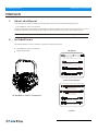
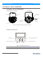
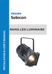
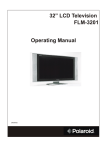
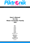
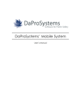
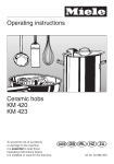
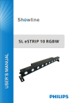
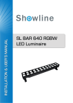
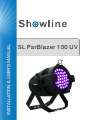
SL ParBlazer 100 UV
Showline Offices
Showline - Dallas
10911 Petal Street
Dallas, TX 75238
U.S.A
Tel: 214-647-7880
Fax: 214-647-8030
Showline - Auckland
19-21 Kawana Street
Northcote, Auckland 0627
New Zealand
Tel: +64 9 481 0100
Fax: +64 9 481 0101
Showline - Europe
Marssteden 152
Enschede 7547 TD
The Netherlands
Tel: +31 53 4500424
Fax: +31 53 4500425
Showline - Asia
Unit C, 14/F, Roxy Industrial Centre
No. 41-49 Kwai Cheong Road
Kwai Chung, N.T., Hong Kong
Tel: +852 2796 9786
Fax: +852 2798 6545
Website:
www.philips.com/showline
The material in this manual is for information purposes only and is subject to change without notice. Showline assumes
no responsiblitity for any errors or omissions which may appear in this manual. For comments and suggestions regarding
corrections and/or updates to this manual, please visit the Showline website at www.philips.com/showline or contact your
nearest Showline office.
Note: Information contained in this document may not be duplicated in full or in part by any person without prior written
approval of Showline. Its sole purpose is to provide the user with conceptual information on the equipment mentioned. The use of
this document for all other purposes is specifically prohibited.
Document Number: SL ParBlazer 100 UV User’s Manual
Version as of: 17th Sep, 2015 Rev1.0
SL ParBlazer 100 UV Installation & User’s Manual
2015 Philips Group. All rights reserved.
SL ParBlazer 100 UV
Installation & User’s Manual
IMPORTANT INOFRMATION
Warnings and Notices
When using electrical equipment, basic safety precautions should always be followed including the following:
READ AND FOLLOW ALL SAFETY INSTRUCTIONS.
Do not mount near gas or electric heaters.
Equipment should be mounted in locations and at heights where it will not readily be subject
to tampering by unauthorized personnel.
The use of accessory equipment not recommended by the manufacturer may cause an unsafe
condition.
Do not use this equipment for other than intended use.
Refer service to qualified personnel.
WARNING: You must have access to a mains circuit breaker or other power disconnect device
before installing any wiring. BE sure that power is disconnected by removing fuses or turning the
mains circuit breaker off before installation. Installing the device with power on may expose you
to dangerous voltages and damage the device. A qualified electrician must perform this installation.
WARNING: Refer to National Electrical Code and local codes for cable specifications.
Failure to use proper cable can result in damage to equipment or danger to personnel.
WARNING: This equipment is intended for installation in accordance with the Nation Electric
Code and local regulations. It is also intended for installation in indoor applications only. Before
any electrical work is performed, disconnect power at the circuit breaker or remove the fuse to
avoid shock or damage to the control. It is recommended that a qualified electrician perform this
installation.
Additional Resources for DMX512
For more information on installing DMX512 control systems, the following publication is available for purchase
from the United States Institute for Theatre Technology (USITT), "Recommended Practice for DMX512: A Guide
for Users and Installers, 2nd edition" (ISBN: 9780955703522). USITT Contact Information:
USITT
315 South Crouse Avenue, Suite 200
Syracuse, NY 13210-1844
Phone: 1.800.938.7488 or 1.315.463.6463
www.usitt.org
Showline Limited Two-Year Warranty
Showline offers a two-year limited warranty of its luminaires against defects in materials or workmanship from the
date of delivery. A copy of the Showline two-year limited warranty containing specific terms and conditions can be
obtained by contacting your local Showline office.
TABLE OF CONTENTS
Showline Offices
IMPORTANT INFORMATION
Warnings and Notices
Additional Resources for DMX512
Showline Limited Two-Year Warranty
TABLE OF CONTENTS
PREFACE
About this Manual
Included Items
SL ParBlazer 100 UV OVERVIEW
SL ParBlazer 100 UV Components
INSTALLATION AND SET UP
Connecting Power
Connecting SL ParBlazer 100 UV to AC Power
Connecting to the DMX512 Network
Mounting Luminaire
Truss / Hanging Applications
Floor Mounting
OPERATION AND PROGRAMMING
LCD Display and Menu System
LCD Display and Menu System Operation
SL ParBlazer 100 UV Menu Tree
Master / Slave Operational Mode
Dimming Curve Selection
DMX CONTROL
SL ParBlazer 100 UV DMX Mapping
Inside Front Cover
1
1
1
3
3
4
5
5
7
8
8
8
9
10
11
12
13
14
8-Bit Mode
14
16-Bit Mode
14
RDM PARAMETER IDs
SL ParBlazer 100 UV RDM Parameter IDs
15
CLEANING AND CARE
Special Cleaning and Care Instructions
Front Lens Cleaning
Service and Maintenance
18
18
18
TECHNICAL SPECIFICATIONS
Operational Specifications
Luminaire Dimensions
2
Table of contents
19
20
SL ParBlazer 100 UV
Installation & User’s Manual
PREFACE
1.
About this Manual
The document provides installation and operation instructions for the following products:
SL ParBlazer 100 UV Luminaire
Please read all instructions before installing or using this product. Retain this manual for future reference.
Additional product information and descriptions may be found on the product specification sheet.
Note: The SL ParBlazer 100 UV luminaire works from 100 to 240 VAC (auto-ranging).
2.
Included Items
Each SL ParBlazer 100 UV luminaire includes the following items:
SL ParBlaz er 100 UV Luminaire
Quick Start Guide
US Market
AC Input cable (1750mm)
(For US, Canada and Latin America market only)
AC Output cable (1000mm)
(For US, Canada and Latin America market only)
DMX Input cable (1000mm)
DMX Output cable (1000mm)
International Market
AC Input cable (1500mm)
(For International market only)
AC Output cable (1000mm)
(For International market only)
SL ParBlazer 100 UV Luminaire
DMX Input cable (1000mm)
DMX Output cable (1000mm)
Cables
About this Manual
3
Installation & User’s Manual
SL ParBlazer 100 UV
SL ParBlazer 100 UV OVERVIEW
1.
SL ParBlazer 100 UV COMPONENTS
Common Luminaire Components
Rear of luminaire
Yoke
Front of luminaire
Safety Cable
Anchor Point
LCD Display / Menu System
Tilt Knob
AC Output
AC Input
DMX512/
RDM Input
DMX512 /
RDM Output
UV LEDs
Figure 1: SL ParBlazer 100 UV Common Components
LCD Display / Menu System
EXIT Button
LEFT Arrow Button
CHECK MARK(OK) Button
RIGHT Arrow Button
Figure 2: LCD Display & Menu System
Note: For Menu operation and programming details, refer to "LCD Display and Menu System" on page 9.
4
SL ParBlazer 100 UV Overview
SL ParBlazer 100 UV
Installation & User’s Manual
INSTALLATION AND SET UP
1.
Power Requirements
The SL Pa rBlazer 100 UV Luminaire operates on AC input voltages from 100 to 240 VAC.
WARN ING! The SL ParBlazer 100 UV luminaire does not have an ON/OFF switch. Always disconnect power input cable
to completely remove power from the luminaire when not in use.
AC Power Operation
When connected to an AC source, the luminaire operates on 100 to 240 volts AC (+/- 10%, auto-ranging). The luminaire
contains an auto-ranging power supply. Each luminaire can draw up to 100 Watts.
WARN ING! The maximum amount of fixtures that may be daisy-chained is (A) 10 luminaires 100 ~ 120VAC or (B) 23
luminaires 230 ~ 240VAC (15 Amps).
Table 1: SL ParBlazer 100 UVVoltage (VAC) vs. Current*
Voltage (AC)
Total Current (A)
Voltage (AC)
100
110
120
130
140
150
160
170
1.00
0.91
0.84
0.77
0.71
0.67
0.63
0.59
180
190
200
210
220
230
240
Total Current (A)
0.56
0.53
0.50
0.48
0.45
0.43
0.42
Note: For wiring of AC input connector, refer to "Connecting SL ParBlazer 100 UV to AC Power" on page 6.
2.
Connecting Power
Luminaires can be powered in one of two ways:
Direct connection to an AC power source using an AC input cable. For wiring of the AC input connector, refer to
"Connecting SL ParBlazer 100 UV to AC Power" on page 6.
Connection from the AC output of another SL ParBlaz er 100 UV. When using this method, it is very important not
to connect any other type of equipment.
WARN ING! Only connect other SL ParBlazer 100 UV luminaires to the AC Output (Thru) connector of
SL ParBlazer 100 UV luminaire.
Installation and Set Up
5
Installation & User’s Manual
SL ParBlazer 100 UV
Connecting the SL ParBlazer 100 UV to AC Power
Table 2 describes how to connect power to your SL ParBlazer 100 UV. Field wiring of the SL ParBlazer 100 UV LED
Luminaire is straight-forward. A total of 3 wires/conductors need to be brought to the luminaire.
The following wiring scheme is required:
Table 2: SL ParBlazer 100 UV AC Input/Output Connections
Wire Color
Purpose
Brown
Blue
Green/Yellow
Main/Line(100 to 240VAC)
Neutral
Ground (Earth)
AC Output
AC Input
Luminaire
Figure 3: SL ParBlazer 100 UV AC Input & Output Connections
6
Connecting SL ParBlazer 100 UV to AC Power
SL ParBlazer 100 UV
3.
Installation & User’s Manual
Connecting to the DMX512 Network
Basic DMX512 installation consists of connecting multiple SL ParBlazer 100 UVs together (up to 32 luminaires) in
"daisy-chain" fashion. A cable runs from the control console (or DMX512 control source) to the DMX connector
on the first SL ParBlazer 100 UV. Another cable runs from the other DMX connector on the first luminaire to
a DMX connector on the next SL ParBlazer 100 UV (or DMX512 device to be controlled).
Luminaire
DMX512/
RDM Input
DMX512/
RDM Output
Figure 4: SL ParBlazer 100 UV DMX512 Input / Output Connections
Note: For more information on DMX512 networking and systems, refer to "Additional Resources for DMX512" on
page 1. For SL ParBlazer 100 UV DMX Mapping, refer to "DMX CONTROL" on page 14 .
DMX512
(from console or
control device)
DMX512 (out from first
to second luminaire)
DMX512 (out to the next
luminaire or DMX512 controlled
device)
DMX512 Conections
DMX512 Signal
XLR Pin
Color
Common (Drain)
1
Black
DMX512-
2
DMX512+
3
White
Red
Note: Remaining pins on each connector are not used.
Figure 5: SL ParBlazer 100 UV- DMX512 Connections
Connecting to the DMX512 Network
7
Installation & User’s Manual
SL ParBlazer 100 UV
4. Mounting Luminaire
Truss / Hanging Applications
The SL ParBlazer 100 UV is provided with the ability to hang via truss hooks, clamps, etc. (sold separately). Simply
attach hook, clamp, etc. to the SL ParBlazer 100 UV yoke through the provided M12 holes. It is recommended
(and may be required by local and national safety codes) to use and install a safety cable (sold separately) as illustrated in
Figure 6. When hanging the fixture, be sure to leave enough space around the luminaire to allow proper, uninterrupted
airflow for cooling and movement. Refer to "Luminaire Dimensions" on page 20 for spacing (dimensional) requirements.
Note: Mounting hooks, clamps, safety cables, etc. are sold separately or by others.
.
Truss Hook or Clamp
(sold separately)
Safety Cable Anchor Point
SAFETY CABLE: Is sold separately and
recommended for all hanging installation and
may be required by national and local codes.
Use the safety cable anchor point for this fixture.
Figure 6: Mounting the Fixture - Hanging Applications
Floor Mounting
The SL Pa rBlazer 100 UV are designed to sit directly on its split yoke assembly in a floor installation application.
When used in this type of application, be sure to leave enough space around the luminaire to allow proper, uninterrupted
airflow for cooling and movement.
8
Mounting Luminaire
SL ParBlazer 100 UV
Installation & User’s Manual
OPERATION AND PROGRAMMING
1.
LCD Display and Menu System
The ProTron LED Luminaire’s LCD Display and Menu System provides local control for accessing the following
fixture’s settings:
DMX Address
Manual Dimming
DMX Personality
Dimming Curve
DMX Fail
Default Setting
Temperature
Firmware
RDM UID
Note: If there are multiple luminaires in a system, changes would need to be made at each LCD Menu as desired.
Upon power up, the LCD will display the main screen showing menu of ProTron LED. The user can use “
and “ ” to select then enter the desired function menu.
”
LCD Display
EXIT Button
CHECK MARK(OK) Button
LEFT Arrow Button
RIGHT Arrow Button
Figure 7: LCD Display and Menu System
OPERATION AND PROGRAMMING
9
Installation & User’s Manual
SL ParBlazer 100 UV
2. LCD Display and Menu System Operation
The LCD Display Menu system consists of several categories. Use the Menu Buttons to access and make changes to
the menu items. When the desired menu item is reached, press the desired Menu Button to display the menu options
and to navigate and configure the menu options as required.
To navigate and access menu settings/selections:
Step 1. Make sure luminaire is powered and turned on.
Step 2. Press the desired button (as shown in Figure 8) to access menu categories.
Step 3. Use LEFT | RIGHT arrow buttons to navigate through the various options and settings.
Step 4. Make changes as desired.
Press CHECK MARK (OK) button to accept changes.
EXIT Button
CHECK MARK(OK) Button
RIGHT Arrow Button
LEFT Arrow Button
Figure 8: LCD Display and Menu System
10
LCD Display and Menu System Operation
SL ParBlazer 100 UV
Installation & User’s Manual
3. SL ParBlazer 100 UV Menu Tree
DMX Address
001--512
Manual Dimming
000%--100%
DMX Personality
DMX 8Bit
DMX 16Bit
Manual
Dimming Curve
Linear Curve
Square Curve
S_Curve
PL_Curve
DMX Fail
OFF
Last Hold
Manual
Default Setting
No
Yes
Temperature
55^oC
Firmware
Rev1.00
RDM UID
0x405101020304
Figure 9: SL ParBlazer 100 UV Menu Tree
SL ParBlazer 100 UV Menu Tree
11
Installation & User’s Manual
SL ParBlazer 100 UV
4. Master / Slave Operational Mode
The Master / Slave Operational Mode allows one SL ParBlazer 100 UV to act as the "Master" luminaire and all other
connected luminaires are controlled by this luminaire. When a luminaire is set to "Slave" mode, it will only listen to and
follow any commands sent from a "Master" luminaire. Only one "Master" luminaire is allowed in this type of operation.
To setup a master / slave network:
Step 1. Set the first device in the DMX512 chain to Master Mode through the luminaire’s menu system.
Step 2. Set all other connected luminaires to Slave Mode.
Step 3. The master luminaire can be controlled via DMX512, RDM or through standalone operation (selfcontained) network utilizing on-board effects). The slave luminaires will mimic the master luminaire’s
operation in all cases.
Note: For more information on DMX512 networking and systems, refer to "Additional Resources for DMX512" on
page 1. For SL ParBlazer 100 UV DMX Mapping, refer to "DMX CONTROL" on page 14.
Master luminaire
Slave luminaire
Slave luminaire
DMX512
(from console or
control device)
DMX512 (out from first
to second luminaire)
DMX512 (out to the next
luminaire or DMX512 controlled
device)
Figure 10: SL ParBlazer 100 UV- Master / Slave Configuration
12
Master / Slave Operational Mode
SL ParBlazer 100 UV
Installation & User’s Manual
5. Dimming Curve Selection
Through the menu, you are able to select one of four dimming curves:
Linear Curve
PL_Curve
S_Curve
Square Curve
PL_Curve *
0
Lumen Output
Lumen Output
Linear Curve
DMX Value
0
DMX Value
*PL Curve follows the dimming curve of Philips Selecon PL
series LED luminaries.
Square Curve
0
Lumen Output
Lumen Output
S_Curve
DMX Value
0
DMX Value
Figure 9: SL ParBlazer 100 UV Luminaire Dimmer Curves
Dimming Curve Selection
13
Installation & User’s Manual
SL ParBlazer 100 UV
DMX CONTROL
This section contains information for operating the luminaire using DMX control in 8-bit mode and16-bit mode.
For Menu options and detailed information, see "LCD Display and Menu System” on page 9.
Note: These tables assume a DMX start address of 1. When a different starting address is used, this address becomes
channel 1 function and the other functions follow in sequence.
1.
SL ParBlazer 100 UV DMX Mapping
8-Bit Mode
Table 3 provides DMX channel mapping of all DMX512 control values when the SL ParBlazer 100 UV LED
Luminaire is in 8-bit DMX512 mode (as set by the luminaire’s menu system).
Table 3: SL ParBlazer 100 UV DMX Channel Mapping ( 8 - Bit Mode)
DMX
Parameter
DMX Range
Range
Defaults
Description
1
LED Intensity
0-255
0-100%
0
LED Intensity
16-Bit Mode
Table 4 provides DMX channel mapping of all DMX512 control values when the SL ParBlazer 100 UV LED
Luminaire is in 16-bit DMX512 mode (as set by the luminaire’s menu system).
Table 4: SL ParBlazer 100 UV DMX Channel Mapping ( 16 - Bit Mode)
DMX
14
Parameter
DMX Range
Range
Defaults
Description
1
LED
0-255
0-100%
0
Intensity Coarse
2
LED
0-255
0-100%
0
Intensity Fine
DMX CONTROL
SL ParBlazer 100 UV
Installation & User’s Manual
1. SL ParBlazer 100 UV RDM Parameter IDs
The following tables outline and describe all the RDM parameters IDs associated with SL ParBlazer 100 UV LED
Luminaires.
Table 5, “SL ParBlazer 100 UV RDM Product Parameters IDs”
Table 6, “SL ParBlazer 100 UV RDM UID”
Table 7, “SL ParBlazer 100 UV RDM Parameters IDs”
Table 8, “SL ParBlazer 100 UV RDM Manufacturer IDs” on page 17
Table 9, “SL ParBlazer 100 UV RDM Manufacturer Specific PIDs” on page 17
Table 5: SL ParBlazer 100 UV RDM Product Parameters IDs
Model ID
Manufacturer
Model Description
0x1230
Philips Entertain. Lighting Asia
Product Category
SL ParBlazer 100 UV
0x2030
Table 6: SL ParBlazer 100 UV RDM UID
UID
MSB of ESTA
50H
MSB of
Unique Seq
LSB of ESTA
41H
LSB of
Unique Seq
MSB of
Unique Seq
LSB of
Unique Seq
Table 7: SL ParBlazer 100 UV RDM Parameters IDs
Get
Allowed
Set
Allowed
RDM Parameter IDs
Value
Comment
Implemented
Category - Network Management
DISC_UNIQUE_BRANCH
0x0001
DISC_MUTE
0x0002
DISC_UN_MUTE
0x0003
PROXIED_DEVICES
0x0010
PROXIED_DEVICES_COUNT
0x0011
COMMS_STATUS
0x0015
Category - Status Collection
QUEUED_MESSAGE
0x0020
STATUS_MESSAGES
0x0030
STATUS_ID_DESCRIPTION
0x0031
CLEAR_STATUS_ID
0x0032
SUB_DEVICE_STATUS_REPORT_THRESHOLD
0x0033
Category - RDM Information
0x0050
SUPPORTED_PARAMETERS
PARAMETER_DESCRIPTION
0x0051
Support required only if
supporting Parameters
beyond the minimum required set.
Support required for Manufacturer
-Specific PIDs exposed in
SUPPORTED_PARAMETERS
message.
SL ParBlazer 100 UV RDM
15
Installation & User’s Manual
SL ParBlazer 100 UV
Table 7: SL ParBlazer 100 UV RDM Parameters IDs
Get
Allowed
Set
Allowed
RDM Parameter IDs
Value
Comment
Category - Product Information
DEVICE_INFO
0x0060
PRODUCT_DETAIL_ID_LIST
0x0070
DEVICE_MODEL_DESCRIPTION
0x0080
MANUFACTURER_LABEL
0x0081
DEVICE_LABEL
0x0082
FACTORY_DEFAULTS
0x0090
LANGUAGE_CAPABILITIES
0x00A0
LANGUAGE
0x00B0
SOFTWARE_VERSION_LABEL
0x00C0
BOOT_SOFTWARE_VERSION_ID
0x00C1
BOOT_SOFTWARE_VERSION_LABLE
0x00C2
Category - DMX512 Setup
DMX_PERSONALITY
0x00E0
DMX_PERSONALITY_DESCRIPTION
0x00E1
DMX_START_ADDRESS
0x00F0
SLOT_INFO
0x0120
SLOT_DESCRIPTION
0x0121
DEFAULT_SLOT_VALUE
0x0122
Category - Sensors 0x02xx
SENSOR_DEFINITION
0x0200
SENSOR_VALUE
0x0201
RECORD_SENSORS
0x0202
Category - Dimmer Settings 0x03xx - FUTURE USE
Category - Power / Lamp Settings 0x04xx
DEVICE_HOURS
0x0400
LAMP_HOURS
0x0401
LAMP_STRIKES
0x0402
LAMP_STATE
0x0403
LAMP_ON_MODE
0x0404
DEVICE_POWER_CYCLES
0x0405
Category - Display Settings 0x05xx
DISPLAY_INVERT
0x0500
DISPLAY_LEVEL
0x0501
Category - Configuration 0x06xx
PAN_INVERT
0x0600
TILT_INVERT
0x0601
PAN_TILT_SWAP
0x0602
REAL_TIME_CLOCK
0x0603
Category - Control 0x10xx
16
IDENTIFY_DEVICE
0x1000
RESET_DEVICE
0x1001
SL ParBlazer 100 UV RDM
Required if device uses a DMX Slot
Implemented
SL ParBlazer 100 UV
Installation & User’s Manual
Table 7: SL ParBlazer 100 UV RDM Parameters IDs
Get
Allowed
Set
Allowed
RDM Parameter IDs
Value
POWER_STATE
0x1010
PERFORM_SELFTEST
0x1020
SELF_TEST_DESCRIPTION
0x1021
CAPTURE_PRESET
0x1030
PRESET_PLAYBACK
0x1031
Comment
Implemented
Table 8: SL ParBlazer 100 UV RDM Parameter Status IDs
Manufacturer Specific messages are in the range of 0x8000 - 0xFFDF. Each Manufacturer-specific Status ID shall have a
unique meaning, which shall be consistent across all products having a given Manufacturer ID. See Table B-2, ANSI E1.20-2010
Status ID Message
Value
Data Value 1
Data Value 2
Status ID Description
00H
00H
ALL OK
8100H
Table 8: SL ParBlazer 100 UV RDM Parameter Specific PIDs
Get
Allowed
Set
Allowed
RDM Parameter IDs
Type
Length
Unit
Prefix
Min
Max
Default
Description
Category - Manufacturer Defined PIDs - Range is 0x80000-0xffdf(See ANSI E1.20-2010 Standard, Table A-3)
8A00H
U8
1
NONE
NONE
0
100
100
8AA1H
S8
1
DB
NONE
0
3
0
Dimming Curve
8A0CH
S8
1
DB
NONE
0
3
0
DMX FAIL MODE
DIMMER
SL ParBlazer 100 UV RDM
17
Installation & User’s Manual
SL ParBlazer 100 UV
CLEANING AND CARE
WARNING! All cleaning should be performed with power completely removed from the luminaire. Never remove
protective covers when luminaire is powered. Wear appropriate protective eye wear and gloves when cleaning the
fixture. All service and maintenance, other than described herein, should be performed by a qualified technician or
Authorized Service Center.
1. Special Cleaning and Care Insturctions
Being a solid-state fixture, and unlike most fixtures, the SL ParBlazer 100 UV requires very little routine
maintenance by the user. This section covers portions of the luminaire that can be removed for cleaning.
The SL ParBlazer 100 UV requires special care when it comes to cleaning the front lens cover. Additional
care needs to be taken with any plastic components because they are much easier to scratch or damage than glass.
Lint free lens tissue
Lint or powder free gloves
Reagent grade isopropyl alcohol*
A mild soap solution
Note: *Reagent grade isopropyl alcohol is good to use on the SL ParBlazer 100 UV plastic optics with
anti-reflection coatings.
If the lens is still dirty after using isopropyl alcohol, for instance if fingerprints or oil is just redistributed and not
cleaned off the optic, then a mild soap and water solution can be used to gently wash the lens. Repeat the cleaning
with isopropyl alcohol to eliminate streaks and soap residue.
WARNING! Under no circumstances should ammonia-based cleaners, acetone, or other harsh solvents be used
on or near the SL ParBlazer 100 UV. These types of cleaners or solvents can permanently damage the optics or
housings of the fixture.
If you have any questions regarding the use or care of your SL ParBlazer 100 UV, please contact Showline technical
support or your local Authorized Dealer.
2. Front Lens Cleaning
Step 1.
Step 2.
Step 3.
Step 4.
Turn Off luminaire and allow to cool completely.
Apply a small amount of reagent grade isopropyl alcohol to lint-free lens tissue.
Wipe all debris, dirt, fingerprints, etc. from lens.
Using a second lint-free lens tissue, wipe off any alcohol residue.
3. Service and Maintenance
For all other service and maintenance issues, please contact your local Showline office or an Authorized Service
Center.
WARNING! Disassembly ( other than as described herein), alterations, unauthorized service, etc. will void the
product warranty. Contact your local Showline office or an Authorized Service Center for technical support and
service.
18
CLEANING AND CARE
SL ParBlazer 100 UV
Installation & User’s Manual
TECHNICAL SPECIFICATIONS
1. OPERATIONAL SPECIFICATIONS
Source:
Beam Angle:
Light Output:
Field Angle:
Input Voltage:
Power Consumption:
Frequency:
Control Protocols:
Ambient Temperature:
Humidity:
Cooling:
Weight:
Housing:
Compliance:
IP Rating:
40pcs High Power UV LED Array
20 Degrees
17,000 mW
38 degrees
100V to 240V(+/- 10%, auto-ranging)
100 Watts(max).
50/60Hz
DMX512(1990) / DMX512A (RDM) / On-Board Menu
-20 to 40 Degrees C ( -4 to 104 Degrees F)
5%-95% Non condensing
Passive convection
17.82 lbs(8.1 kg) - Luminaire only (no mount, AC input cable or accessories)
Die Cast aluminium with Powder Coating
CB, cETL, C-Tick, FCC and CE Marked (International models)
IP65
Note: Common model specifications shown. For specific model specifications, features, and accessories, refer
to the product specification sheet for more details.
OPERATIONAL SPECIFICATIONS
19
Installation & User’s Manual
2. Luminaire Dimensions
20
LUMINAIRE DIMENSIONS
SL ParBlazer 100 UV
SL ParBlazer 100 UV
Installation & User’s Manual
NOTE
21
C 2015 Philips Group