1
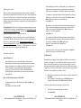
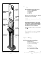
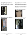
Trademarks TM Microsoft® Windows™, Windows®98, Windows® 2000, and Windows® NT are registered trademarks of Microsoft Corporation. Intel®, Pentium® III and Celeron™ are registered trademarks of Intel corporation. Other trademarks and registered trademarks of products appearing in this manual are the properties of their respective owners. SeePoint Interactive Computing Systems Patents The product(s) described herein is(are) covered by U.S. Patent No. 427,597 and other patents pending. User’s Manual Version 2.4.4 © 1998-2005 All Rights Reserved CounterPoint VantagePoint VantagePoint Print WallStation All-In-One SecurePoint HotelPoint TicketPoint Copyright This publication contains information that is protected by copyright. No part of it may be reproduced in any form or by any means or used to make transformations/adaptations without prior written permission from SeePoint Technology. This publication is provided for informational purposes only. The manufacturer makes no representations or warranties with respect to the contents or use of this manual and specifically disclaims any express or implied warranties of merchantability or fitness for any particular purpose. The user assumes the entire risk of the use or the results of the use of this publication. SeePoint Technology reserves the right to revise this publication and make changes to its content at any time, without the obligation to notify any person or entity of such revision changes. www.SeePoint.com 2619 Manhattan Beach Blvd. • Redondo Beach, CA 90278 • (310) 725.9660 Fax (310) 535.9234 1 www.SeePoint.com 2619 Manhattan Beach Blvd. • Redondo Beach, CA 90278 • (310) 725.9660 Fax (310) 535.9234 2 Table of Contents Introduction Introduction............................................................................................4 Package Contents..........................................................................4 Quick Start Guide...................................................................................5 Safety Instructions................................................................................12 Voltages...........................................................................................12 Removing & Carrying the VantagePoint System............................13 Installation............................................................................................15 Mounting Instructions .....................................................................15 Restocking Paper in the VantagePoint Print ...................................17 Installing and Removing the Counterweight ...................................18 LAN ................................................................................................19 Wireless Network............................................................................19 Peripherals.......................................................................................19 Care Instructions .............................................................................20 Repacking your System...................................................................21 Kiosk Software Options ..................................................................21 Internet Explorer –K...................................................................21 How to Start Internet Explorer in Kiosk Mode...........................21 For WindowsXP .........................................................................22 Netkey Creator & Netkey Creator Studio...................................23 Netkey Manager .........................................................................23 Reinstalling Software ......................................................................23 Original Settings..............................................................................23 Installation Instructions for Signage ....................................................24 Front Panel Signage ........................................................................26 Acrylic Overhead Panel Signage.....................................................26 Warranty ..............................................................................................29 Customer Service Program ..................................................................33 FAQ & Trouble Shooting ....................................................................36 Contact Information .............................................................................40 SeePoint provides a complete suite of interactive computing systems. These dedicated kiosk appliances are very east to set up, install and maintain. From an application view, your new system is designed to act and react just like your desktop computer. Any web based solution or software package that runs on your Wintel or Linux system can run on SeePoint’s products. SeePoint’s team of product designers and engineers are experts in integrating peripherals and creating custom solutions for both hardware and software. If you have a special need, please let your account manager or reseller know. Additionally, if SeePoint can help in any way, please do not hesitate to call. Thank you, Jonathan Arfin President & CTO Package Contents You should receive the following items with your SeePoint system: q q q q q q q SeePoint Kiosk System Recovery Disk or Full Operating System User’s Manual Approved Driver CD 1 Power Cord Allen Wrench Key Quality Control Certificate Optional q q q www.SeePoint.com 2619 Manhattan Beach Blvd. • Redondo Beach, CA 90278 • (310) 725.9660 Fax (310) 535.9234 3 Wall Mounts – Wall Mount Bracket VantagePoint Print – Set of Keys Peripheral Driver Disks, Manuals and Cables www.SeePoint.com 2619 Manhattan Beach Blvd. • Redondo Beach, CA 90278 • (310) 725.9660 Fax (310) 535.9234 4 To connect the power cord, plug the female end of the power cord into the connection on the system’s Connection Panel. Plug the male end of the power cord into a standard electrical outlet. Please refer to the Safety Instructions in this manual for other important information concerning operation of your SeePoint system. Quick Start Guide 1. 2. 3. 4. Inspect Package Contents a. Please keep your packaging. b. Notify SeePoint immediately of any missing components. Please notify shipper within 24 hours of any damaged goods. 5. a. There are no user serviceable parts inside the SeePoint system; opening the system voids your warranty. Please contact SeePoint for any service requests or upgrades. Locating the Connection Panel – For CounterPoint, VantagePoint and WallStation products, the Connection Panel is located underneath the right rear corner of the base. For the SecurePoint, the Connection Panel is located on the power caddy which is mounted underneath the surface to which the system is installed. For the All-in-One, the Connection Panel is behind the Access Panel which is at the bottom of the back of the system. The Connection Panel includes the power switch as well as connecting points for the power cord, network jack and optional phone plug. Power Cord Installation – SeePoint systems ship set to operate on 110V current (North American standard). If you require 220V current, you will need to flip the voltage switch in the system. Please refer to the safety instructions in this manual for information regarding this system adjustment. www.SeePoint.com 5 Network – A standard RJ-45 network jack is located on the system’s Connection Panel. A To reduce the risk of fire standard Category 5 cable for or electrical shock, do not any Local Area Network or High expose this product to Speed Modem may be used with water or moisture. this jack. Please contact your network provider for exact network settings. SeePoint systems ship ready to work with a DHCP compliant router. If you are not using a DHCP compliant router, you will need to adjust the TCP/IP settings on your system. To give your system a ‘home’ on your network, use the ‘Start’ button on the ‘desktop.’ Go to ‘Settings’ and then ‘Network and Dial Up Connections.’ Double click the appropriate icon and follow the prompts. Opening the Access Panel – The system’s access panel is located at the bottom of the back of the computer enclosure. The panel is secured with two screws, either standard Philips or secure screws. If the access panel uses secure screws, the proper wrench is included with your packaging. Remove both screws and the access panel door will swing down and out. This will give you full access to the I/O plate to connect external hardware devices such as CD-ROMs and Floppy Drives. If the system needs to be operated with a cable connected to a port on the I/O plate, run the cable thru the slot in the access panel door and reattach. 2619 Manhattan Beach Blvd. • Redondo Beach, CA 90278 • (310) 725.9660 Fax (310) 535.9234 Network or Phone Installation Note: Many systems include 802.11b wireless network preinstalled at the factory. Please check your order for exact system configuration. Phone – If your system is equipped with a modem, then there will be a white RJ-11 phone jack installed in the system’s Connection Panel. To set up the dial up connection with your ISP, use the ‘Start’ button on the ‘desktop.’ Go to ‘Settings’ and then ‘Network and Dial Up Connections.’ Double click the appropriate icon and follow the prompts. 6. Dual Power Switches a. On the Connection Panel – The system’s main power switch is a two position toggle switch located on its Connection Panel. The main power switch controls all accessories, computer components and amplified speakers. Wake on LAN will not function with this switch in the OFF position. www.SeePoint.com 2619 Manhattan Beach Blvd. • Redondo Beach, CA 90278 • (310) 725.9660 Fax (310) 535.9234 6 b. Inside the Access Panel – A standard computer ‘soft switch’ is located on the I/O Plate behind the access panel. This switch, when depressed and released, will issue an orderly shut Please do not expose this down command to the system. If the product to extreme heat. system does not respond to the orderly shut down command, hold the switch for seven seconds to force a hard shutdown of the computer. c. Note: The amplified speakers and powered accessories will be left on until the main power switch is toggled to the off position. 7. Calibrating The Touch Screen – Begin by identifying the type of touch screen on the kiosk. To do so, find the silver serial label on the back of the kiosk, and look at the “Config” line. The “Config” line will indicate either “BERG,” “EELY” or “ELO.” a. Calibrating the BERG Touch Screen -- From the ‘Start’ menu, go to ‘Programs’ and then ‘Hampshire TSHARC Control Panel.’ From the Control Panel, select the Calibration tab. Touch the target inside the red arrows to begin the calibration routine. Touch each of the targets inside the red arrows until the word ‘release’ appears on the screen. Next, touch the target, and move your finger along the screen. If the target tracks your finger, then the touch screen is properly calibrated. Touch the ‘Accept’ button on the lower left corner of the screen. If the target does not track your finger, touch the ‘Cancel’ button. From the pop up, touch the ‘Configure’ button, and then select 7-point calibration option and ‘Okay.’ Touch each of the targets inside the red arrows until the word ‘release’ appears and complete the calibration routine as described above. b. Calibrating the EELY Touch Screen – From the ‘Start’ menu, go t all programs and select the EELY touch logical driver. The next page you see will be titled “Main Console.” In the lower right-hand quadrant of the “Main Console,” you will see a function titled “Calibration Tools.” Select the 4 point calibration. When the target appears on the screen, touch and hold the target until you hear a beep. With each of the 3 additional targets that appear, touch and hold the target each time until it beeps. After you www.SeePoint.com 2619 Manhattan Beach Blvd. • Redondo Beach, CA 90278 • (310) 725.9660 Fax (310) 535.9234 7 touch the fourth target, the “Main Console” page will reappear. Select the “Okay” button which can be found on the lower right corner of the page. Calibrating the ELO Touch Screen -- From the ‘Start’ menu, go to ‘Settings’ and then ‘Control Panel.’ From that menu select or double click the ELO icon. From the pop up panel, select CALIBRATE or ALIGN. From a position of normal use, touch on each target as it appears, and then follow the prompts. Thoroughly test your calibration. If the touch screen is properly calibrated, the cursor will jump smoothly to underneath your fingertip. It is recommended that the touch screen be calibrated every time the system is relocated as the touch screen may drift during shipping. Additionally, occasional recalibration will ensure a user-friendly experience each and every time. 8. Pivoting the Kiosk Head – The angle of the screen may be changed by loosening the secure bolts or knobs which are in the center of the pivot elbow, adjusting the angle of the system head and the tightening the bolts or screws. a. Secure Bolts -- Using the supplied wrench, loosen each side slowly and equally without completely disengaging the bolt. The pivot mechanism will gradually allow the head to tilt. Set the head to a comfortable viewing angle and tighten the bolts so the head remains securely in place. Do not over tighten the bolts. Be sure to loosen the bolts slowly so the computer enclosure does not swing down. It is also recommended that you do not leave the pivot bolts loose or remove them entirely. For those applications where you want the end-user to be able to adjust the head, please request a set of knobs to replace the secure bolts on your system. b. 9. Knobs – The knob option should only be used in a highly controlled environment as they can be removed, causing physical instability to the system. To move the system head, loosen the knobs until the head begins to pivot readily. Set the angle, and then retighten the knobs. Updating Software a. Using the Network www.SeePoint.com 2619 Manhattan Beach Blvd. • Redondo Beach, CA 90278 • (310) 725.9660 Fax (310) 535.9234 8 b. i. To update software on the system via the network, you must first have the correct network permissions to do so. Speak to your network administrator to see if you have these permissions. ii. Some of your network settings may need to be reconfigured so the kiosk will be able to talk to your network. Your network administrator will need to do this as the settings are unique to your company. iii. Plug the network cable into the network connection on the system. iv. Take the file you want to install on the kiosk and place it on the network drive. (Make a note of the file location.) The file you want installed on your kiosk may reside on any hard drive, zip drive, CDROM drive or any other device that is connected to your network. v. Once you are on the network you will need to click on the network places icon on the desktop of the kiosk. vi. From the display of your kiosk, you will now see a list of the computers on your network. vii. Go to the location where you placed the file you want to install/backup. viii. Copy the file to the destination you specify on the kiosk, or backup the file to the network drive you choose. Using a Floppy Drive i. Shut down the system using the “Start” menu on the desktop. Toggle the power switch to the off position. ii. Remove the access panel to expose servicing ports and power connections. iii. Connect a keyboard to the keyboard port which is labeled on the I/O plate. (If your system has an integrated keyboard, skip this step.) iv. Restart your system by toggling the power switch to the on position, and enter the setup by pressing “F2” at the first boot screen. v. Once the setup screen appears you will highlight “General Configuration” by using the up/down arrow keys and press “Enter.” vi. A setup screen will appear that allows you to specify which type of floppy you have. You will need to set www.SeePoint.com 2619 Manhattan Beach Blvd. • Redondo Beach, CA 90278 • (310) 725.9660 Fax (310) 535.9234 9 c. “Floppy A” to 1.44. (The system’s default setting for Floppy A is “none.”) vii. “Floppy A” is the first device that the system will look for during the boot sequence. This is the default setting. Do not change it. viii. Save the changes, and power off the system. ix. From the area where you removed the access panel, pull out the wide gray cables that are tucked into the enclosure. Connect the floppy cable, which is the longer of the two cables, to the floppy drive. (The orientation of the floppy cable is correct if the red stripe along the edge of the gray cable is aligned with pin 1 on the floppy drive.) x. Connect the service power pigtail to the floppy drive. xi. Restart the system, allowing it to boot normally so you can use the floppy to add software or backup files. xii. Note: If you are booting to the floppy drive, restart the system with your bootable media inside Floppy A. Using a CD-ROM Drive i. Shut down the system using the “Start” menu on the desktop. Toggle the power switch to the off position. ii. Remove the access panel to expose servicing ports and power connections. iii. Connect a keyboard to the keyboard port which is labeled on the I/O plate. (If your system has an integrated keyboard, skip this step.) iv. Restart your system by toggling the power switch to the on position, and enter the setup by pressing “F2” at the first boot screen. v. Once the setup screen appears, highlight “General Configuration” by using the up/down arrow keys and press “Enter.” vi. A setup screen will appear that allows you to specify the boot sequence. vii. Because the first boot device is set to “Floppy A” by default, you will need to change the first boot device to “CD-ROM” by using the right arrow key. viii. Save the changes, and power off the system. ix. From the area where you removed the access panel, pull out the flat gray cables that are tucked inside the enclosure. Connect the IDE cable, which is the www.SeePoint.com 10 2619 Manhattan Beach Blvd. • Redondo Beach, CA 90278 • (310) 725.9660 Fax (310) 535.9234 d. e. shorter of the two gray cables, to the CD-ROM drive. (The orientation of the IDE cable is correct if the red stripe along the edge of the gray cable is aligned with pin 1 on the CD-ROM drive.) x. To power the CD-ROM drive, connect the drive to the 4-pin Molex connector inside of the access panel. xi. Restart the system, allowing it to boot normally so you can use the drive to add software or backup files. xii. Note: If you are booting to the CD-ROM drive, restart the system with your bootable media inside the drive. Using a USB Device i. With the system powered on, remove the access panel to expose servicing ports and power connections. ii. Connect the USB cable that comes with the device into either of the two USB ports which are accessible from the I/O plate behind the access panel. iii. Use the touch screen to complete the installation wizard which will be displayed on the screen after you install the USB device. iv. Note: If the SeePoint system does not detect the USB device you are trying to attach to it, it may be necessary to install the driver before the USB device will work. Refer to the driver installation instructions that came with the USB device that you are using. Using Other Storage Devices Your SeePoint kiosk can use a wide variety of devices for software updates. If you wish to use a device that is not listed above, please contact SeePoint technical support for assistance. 10. Remote Desktop – XP Only If you have Windows XP, you will see a SeePoint Customer Service icon on your ‘desktop.’ By activating this you are ‘inviting’ a SeePoint representative onto your computer to perform certain diagnostics. 11. Shutting Down the System – The preferred method for turning off your system is by using the ‘Shut Down’ function on the ‘Start’ menu. After going through the shut down process, toggle the switch on the system’s Connection Panel to the off position. For the All-in-One, use ‘Shut Down,’ and then unplug the system from the outlet. www.SeePoint.com 11 2619 Manhattan Beach Blvd. • Redondo Beach, CA 90278 • (310) 725.9660 Fax (310) 535.9234 Safety Instructions Voltages 1. 2. 3. 4. 5. 6. To avoid damaging your computer, be sure that the voltage selection switch is set to match the AC power available at your location: a. 115V/60Hz in most of North and South America and some Far Eastern countries such as South Korea and Taiwan b. 230 V/50Hz in most of Europe, the Middle East and the Far East c. 100V/50Hz in eastern Japan and 100V/60Hz in western Japan. NOTE: The voltage selection switch must be set to the 115V position even though the AC supply in Japan is 100V. To change the voltage selection switch on CounterPoint and WallStation products: a. Shut down and power off the system. b. Set the system on a soft surface so the metal chassis underneath the base faces you. c. Using a flat blade screwdriver, gently pop off the quarter sized metal cover to expose the red voltage selection switch. If the system is set to run on 110V, you will see the number 115. d. To change the current to 220V, use a flat blade to flip the switch. To change the voltage selection switch on other SeePoint products, please contact technical support. To decrease the possibility of shorting out your computer when disconnecting a network cable, first unplug the cable from the network adapter on the back of your computer, and then from the network jack. When reconnecting a network cable to your computer, first plug the cable into the network jack, and then into the network adaptor on the system. To avoid possible damage to the system board, wait five seconds after turning off the computer before disconnecting or connecting a nonUSB device from the computer. (Includes KEYBOARD AND MOUSE.) To help prevent electric shock, plug the system and any device power cables into properly grounded power sources. These cables are equipped with 3-Prong plugs to help ensure proper grounding. Do not use adapter plugs or remove the grounding prong from a cable. If you www.SeePoint.com 12 2619 Manhattan Beach Blvd. • Redondo Beach, CA 90278 • (310) 725.9660 Fax (310) 535.9234 must use an extension cable, use a 3-wire cable with properly grounded plugs. 7. Be sure that nothing rests on the system’s cables and that the cables are not located where they can be stepped on or tripped over. 8. Do not spill food or liquids on your system. 9. Do not push any objects into the openings of your system. Doing so can cause fire or electric shock by shorting out interior components. 10. Keep your system away from radiators and heat sources. Also, do not block cooling vents or position your system in a way where air flow is impeded. 11. CAUTION: Improper or prolonged keyboard use may result in injury. 12. CAUTION: Viewing the monitor screen for extended periods may result in eyestrain. DO NOT ATTEMPT TO SERVICE THE SYSTEM YOURSELF. Please contact an authorized service center or SeePoint. Removing & Carrying the VantagePoint System 1. 2. 3. 4. 5. 6. When you receive your VantagePoint system check packaging for damage and report it to your shipper immediately. To unpack your system, cut the four straps that are around the box. A razor knife is best for this. Lift off the top of the box. Remove the specially designed foam that covers the top of your system by lifting it straight off. The foam fits tightly around the top of the system so some effort may be required to pull the foam off. It is advisable to have another person hold the box while lifting the top foam off the system. The bottom of the VantagePoint system sits in a foam base. Lift your system out of the bottom foam packaging by gripping the long vertical support tubes on each side of the system. SeePoint recommends the use of two people for this procedure. Do not pull the system out of the box by the head. If you need to move the system once it has been unpacked, carry the system by holding the vertical support tubes. Again, the use of two people is recommended. Do not carry the system by holding the head. You can also use a dolly to move the system, but be sure to point the LCD screen away from the dolly. Note: Save your packaging in the event that you need to transport your VantagePoint at a later date. www.SeePoint.com 13 2619 Manhattan Beach Blvd. • Redondo Beach, CA 90278 • (310) 725.9660 Fax (310) 535.9234 www.SeePoint.com 14 2619 Manhattan Beach Blvd. • Redondo Beach, CA 90278 • (310) 725.9660 Fax (310) 535.9234 Installation c. Mounting Instructions d. 1. a. b. c. d. e. f. CounterPoint If you ordered a mounting kit with your CounterPoint, your system may be mounted to a surface. The mounting kit consists of three brackets and four screws. The first two brackets, the left and right hand support brackets, are mounted underneath the base of the system at the time of manufacture by SeePoint. The third bracket, which is the rectangular mounting bracket, will need to be mounted by you to the desired surface. The size of hole and hardware necessary to mount the rectangular mounting bracket will depend on the composition of the material to which the bracket is being mounted. SeePoint recommends that you consult a licensed building contractor to help you make these determinations. Use the template provided to determine the locations of the holes that will be drilled to mount the rectangular mounting bracket. The rectangular mounting bracket has a top and a bottom. The bracket is correctly oriented when the longer slots are at the top and the shorter slots are at the bottom. Once the rectangular mounting bracket is mounted to the surface, lift the system by the support arms and slide the system onto the mounting bracket so it locks in place. Make sure that all of the tabs on the left and right hand support brackets are engaged with the slots on the rectangular mounting bracket. Use the four screws provided in your mounting kit to screw the mounting bracket to the support brackets from the oval-shaped holes on the outside edge of the mounting bracket. e. f. 3. a. b. c. d. e. f. 2. a. b. WallStation Your WallStation kiosk includes a mounting kit which enables you to mount the system to a wall. The mounting kit consists of three brackets and four screws. The first two brackets, the left and right hand support brackets, are mounted underneath the base of the system at the time of manufacture by SeePoint. The third bracket, which is the rectangular mounting bracket, will need to be mounted by you to the wall. The size of hole and hardware necessary to mount the rectangular mounting bracket will depend on the composition of the material to which the bracket is being mounted. SeePoint recommends that you consult a licensed building contractor to help you make these www.SeePoint.com 15 2619 Manhattan Beach Blvd. • Redondo Beach, CA 90278 • (310) 725.9660 Fax (310) 535.9234 g. h. determinations. DO NOT mount the system to drywall as it will not support the weight of the system. Use the template provided to determine the locations of the holes that will be drilled to mount the rectangular mounting bracket. The rectangular mounting bracket has a top and a bottom. The bracket is correctly oriented when the longer slots are at the top and the shorter slots are at the bottom. Once the rectangular mounting bracket is mounted to the wall, lift the system by the support arms and slide the system onto the mounting bracket so it locks in place. Make sure that all of the tabs on the left and right hand support brackets are engaged with the slots on the rectangular mounting bracket Use the four screws provided in your mounting kit to screw the mounting bracket to the support brackets from the oval-shaped holes on the outside edge of the mounting bracket. Secure Point The Secure Point mounts directly to flat surfaces such as a tabletop. SeePoint will provide you with a blueprint to assist you in the mounting of your system. From the blueprint, you can make a template to correctly mount your SecurePoint to the desired surface. SeePoint strongly recommends that you use a qualified contractor to install your SecurePoint system. The minimum surface thickness for installation of your system is 1”. Using the drill template, mark the locations on the installation surface where the vertical SecurePoint support tubes should be installed. Using a hole saw, drill two 1.250” holes into the surface. It is critical that the correct size hole saw be used or the system will not fit tightly with the surface. Put the threaded end of the support tube into the holes drilled into the surface. Underneath the installation surface you will see the threaded end of the support tube. For each tube, install the 1-1/4” washer and jam nut onto the threaded end of the support tube. Using a pair of channel locks or a large wrench, firmly tighten the jam nut against the underside of the mounting surface. Once the jam nut is flush against the surface, turn the jam nut one additional time to lock it into place. Do not over tighten the jam nut. Over tightening may damage the installation surface. To install the computer system, orient the screen so it faces the user, and feed the wires that come out of the system’s elbows down into the support tubes. www.SeePoint.com 16 2619 Manhattan Beach Blvd. • Redondo Beach, CA 90278 • (310) 725.9660 Fax (310) 535.9234 i. j. k. 4. a. b. c. d. Set the system onto the support tubes, making the ends of the support tubes fit inside of the elbows on the system. Do not pinch or nick the wiring. Once the support tubes have been completely inserted into the elbows, lock down the elbows by tightening the set screws at the bottom of the elbows with the security wrench that was provided with your system. Connect the wires hanging from the bottom of the support tube underneath the installation surface as necessary. All in One The All in One model has a standard VESA4 mounting adaptor on the back. This adaptor will allow the system to mount to all of the VESA4 compliant mounts on the market. Secure your VESA4 mount to the desired mounting surface. Refer to the instructions provided with your VESA4 mount regarding proper installation. Once the mount is properly and securely attached to the mounting surface, match the VESA4 mounting holes on the system’s mounting adaptor to the mounting holes on the VESA4 mount. Secure the system to the mount using the fasteners provided with your VESA4 mount. Once the system is mounted, plug in the system, and make any other necessary connections. 7. 8. 9. 10. Pull approximately 6” of paper out of the printer, and close the top. The printer will auto detect the paper, feed it and cut off the excess. Close and lock the system’s cabinet door. Test to make sure you have successfully installed the paper. If your system prints on paper that is 8.5” wide: 1. 2. 3. 4. 5. 6. 7. 8. 9. Obtain the correct replacement paper. Contact SeePoint, and ask for replacement paper for the IP-KPM216, which is part number SP.900007.A. Open the rear door of your VantagePoint Print kiosk using the keys that were supplied with your system You will see an empty paper core on a spindle. Remove the spindle by lifting it out of the holder. Remove the empty paper core from the paper spindle. Insert the spindle into the core of the new paper roll. Re-hang the spindle with new paper roll onto the paper roll holder. Feed the end of the paper into the feed slot on the printer. The printer will grab the paper and auto feed it into the printer. The printer is now ready for use. Close and lock the system’s cabinet door. Test to make sure you have successfully installed the paper. Restocking Paper in the VantagePoint Print Installing and Removing the Counterweight If your system prints on paper that is 80mm wide (3.125”): 1. 2. 3. 4. 5. 6. Obtain the correct replacement paper. Either purchase standard 80mm receipt paper from an office supply store, or contact SeePoint and purchase part number SP.900-006.A. Open the rear door of your VantagePoint Print kiosk using the keys that were supplied with the system. Open the printer housing by pushing the release button. The release button is in the lower right corner of the beige plastic printer housing and depicts an arrowhead pointing downward. The printer housing will now be open, exposing the core of the depleted roll of paper. Remove and discard the old core. Place your replacement roll inside the printer housing, making sure that the paper is oriented correctly. Refer to the instructions inside of the printer housing for proper orientation. If the new roll of paper is not oriented correctly, the paper will come out without printing. www.SeePoint.com 17 2619 Manhattan Beach Blvd. • Redondo Beach, CA 90278 • (310) 725.9660 Fax (310) 535.9234 The counterweight is a 25 pound weight installed in the base of your VantagePoint system. The weight adds stability to the system, and in most cases, should remain in the base of the kiosk. However, in the event that you want to make the system easier to move around, the weight may be removed and reinstalled. Installing the Counterweight 1. 2. 3. 4. 5. Unplug the kiosk from the outlet. Move the enclosure of the unit to the vertical position, and tighten the pivot arm bolts or knobs to lock the enclosure in place. Put some padding on the floor. Carefully lower your VantagePoint system to the ground so the back of the enclosure is on the floor and the LCD is facing up. At the base of the unit you will see the mounting post for the weight. Slide the opening in the center of the weight onto the post. www.SeePoint.com 18 2619 Manhattan Beach Blvd. • Redondo Beach, CA 90278 • (310) 725.9660 Fax (310) 535.9234 6. 7. Put the ¼ x 20 x 5/8” bolt into the threaded hole in the post and tighten. Stand your unit up to its normal operating position. Removing the Counterweight 1. 2. Unplug the kiosk from the outlet. Move the enclosure of the unit to the vertical position, and tighten the pivot arm bolts or knobs to lock the enclosure in place. 3. Put some padding on the floor. Carefully lower your VantagePoint system to the ground so the back of the enclosure is on the floor and the LCD is facing up. 4. At the base of the unit you will see the counterweight with a mounting bolt (¼ x 20 x 5/8”) in the center. 5. Remove the bolt using a 7/16” wrench. 6. Slide the weight off the post. Once the weight has been removed, stand your unit up to its normal operating position. LAN For instructions regarding connecting your kiosk to a Local Area Network, please refer to the Quick Start Guide in this manual. Star Micronics 80 MM Receipt Printer Custom IT 8.5” Thermal Printer Welch-Allyn Bar Code Reader Keyboards & Mice Touch Screens On-Board Graphics On-Board LAN The SeePoint plastic and metal kiosk housings and stands may be cleaned with warm soapy water. Apply a small amount of the soapy water to a soft, lint-free cloth, and wipe down the system. Be careful that water does not drip or seep into the computer housing. Systems with Touch Screens ELO, the touch screen manufacturer, recommends the following care instructions: • If your system includes wireless Internet connectivity, you will see a small green icon with an arrow displayed in the task bar when the system is powered on. If the kiosk system is within the approved range of your Access Point (transmitter), then the kiosk system is preconfigured to automatically connect to your network. If you see the icon and your system still does not log onto your network, please refer to the trouble-shooting guide included with your wireless software. If you do not see the wireless network icon, please contact SeePoint technical support. • Peripherals • • • http://www.magtek.com http://www.intel.com 19 2619 Manhattan Beach Blvd. • Redondo Beach, CA 90278 • (310) 725.9660 Fax (310) 535.9234 Use household cleaners such as Windex™ or an ammonia-based solution to clean the touch screen. Spray the cleaner onto a soft, lint free cloth. Wipe the screen with the cloth. Never spray the cleaner directly onto the screen as seepage and cloudiness may result. Be careful that the cleaner does not seep or drip into the system. Systems without Touch Screens If your system does not have a touch screen, the LCD is protected by a Lexan® panel. Please adhere to the following care instructions when cleaning your system: • For information on supporting a particular peripheral device, please go to the following websites: www.SeePoint.com http://www.custom.it http://www.handheld.com http://www.seepoint.com/support.asp http://www.seepoint.com/support.asp http://www.seepoint.com/support.asp http://www.seepoint.com/support.asp Care Instructions Wireless Network Card readers Intel Digital Camera http://www.starmicronics.com Do not use household cleaners to clean the Lexan panel. The chemicals in these cleaners may cause a reaction with the Lexan. Only use soapy water and a soft cotton cloth to clean the panel. Put a small amount of soapy water on the cloth and wipe the screen. Be careful that water does not seep or drip into the system. Never spray water directly on the screen. www.SeePoint.com 20 2619 Manhattan Beach Blvd. • Redondo Beach, CA 90278 • (310) 725.9660 Fax (310) 535.9234 Repacking your System When running Internet Explorer in Kiosk mode, you can make Internet Explorer open to a default web page or application of your choosing – either on your own computer or on another computer on your network. Make sure to keep the original packaging in which your kiosk was shipped. Many models are shipped with custom foam inserts that fit to the head and base of the unit. The foam pieces are contoured to the system to provide maximum protection and only fit on the system one way. If you do not have the original packaging, please contact SeePoint to arrange to have new packaging shipped to you for a small fee. For example, to start Internet Explorer in Kiosk mode and have Internet Explorer open to the SeePoint web site by default, click Start, point to Run, and then type iexplore -k www.SeePoint.com in the Open box. Alternatively, to start Internet Explorer in Kiosk mode and run Internet Explorer with the Example.htm web page that is located in the Kiosk folder on your computer, click Start, point to Run, and then type iexplore -k "c:\kiosk\example.htm" in the Open box. For CounterPoint: Fit the two base foam pieces around the base of the system. Carefully lift the system into the original shipping box. Do not pick the system up by the enclosure containing the LCD. Place the remaining foam pieces around the computer enclosure. Close and seal the box. Or, to start Internet Explorer in Kiosk mode and run Internet Explorer with the Example.htm web page that is located on another computer on your network, click Start, point to Run, and then type iexplore –k "network drive:\kiosk\example.htm" in the Open box. For VantagePoint: Using the vertical support tubes, carefully pick up the VantagePoint and place it into the square base box, which is approximately six inches deep, containing the base foam. Do not pick the system up by the enclosure containing the LCD. Put the remaining foam piece onto the top of the system around the computer/LCD enclosure. Slip the larger box over the top of the system. Secure the boxes together with strapping tape. If you do not specify a web page or other application in the Open box, Internet Explorer opens your default start page. Kiosk Software Options For WindowsXP Internet Explorer –K Kiosk mode means setting the browser window to full screen view with just a scroll bar for navigation. To provide additional controls, such as access to the Back, Forward or Refresh buttons, you can set Internet Explorer 6 in partial kiosk mode, which includes a smaller toolbar at the top of the browser window. To add a Full Screen button to this toolbar, so that you can move easily from full screen view to the standard browser window, do this: Internet Explorer can be set to run in Kiosk mode. When you run Internet Explorer in Kiosk mode, the Internet Explorer title bar, menus, toolbars and status bar are not displayed, and Internet Explorer runs in Full Screen mode. You can switch to other running programs by pressing ALT+TAB or CTRL+ALT+DEL. SeePoint offers kiosk keyboards with these keys disabled to prevent end users from exiting your application. 1. How to Start Internet Explorer in Kiosk Mode 2. To start Internet Explorer in Kiosk mode, click Start, click Run, type iexplore -k in the Open box, and then click OK. To hide the toolbar at the top of the window entirely, do this: 1. 2. www.SeePoint.com Right-click the toolbar at the top of the browser window, and then click Customize. In the Customize Toolbar dialog box, click Full Screen under Available toolbar buttons, click Add, and then click Close. 21 2619 Manhattan Beach Blvd. • Redondo Beach, CA 90278 • (310) 725.9660 Fax (310) 535.9234 When in full screen mode, right-click the toolbar. Click Auto-Hide. www.SeePoint.com 22 2619 Manhattan Beach Blvd. • Redondo Beach, CA 90278 • (310) 725.9660 Fax (310) 535.9234 Now you can view Web pages at full size without any controls getting in the way. When you want to view the toolbar again, move the pointer over the top of the Web page. If you don’t want to add a Full Screen button to the toolbar, you can also toggle between full screen and the standard view by pressing F11. Installation Instructions for Signage Netkey Creator & Netkey Creator Studio To try a free 30 day trial of Netkey’s award winning kiosk operating software products – Netkey Creator and Netkey Creator Studio – go to c:\netkey, select the icon for the product that interests you and follow the instructions provided by the installation wizard. Netkey Manager For more information about Netkey’s remote management software, Netkey Manager, please contact your account manager. Reinstalling Software For instructions regarding reinstallation of the software purchased with your system, please refer to the ‘Updating Software’ section of this manual’s Quick Start Guide, and use the bootable media (usually a CD-ROM) that came with your system. Original Settings 1. Graphics Display Chipset: Intel 815E GMCH Resolution: 1024 x 768 24 bit true color Driver version: 6.6 (Provided by Intel) 2. BIOS Settings General Configuration a. Floppy A to “NONE” b. First boot device to “ Floppy A” c. Second boot device to “HDD-0” d. Third boot device to “CD-ROM” e. Fourth boot device to “ USB ZIP/FLASH” Power Management a. Set PWRON after PWRFAIL to “ON” All other BIOS settings are set to the default settings. www.SeePoint.com 23 2619 Manhattan Beach Blvd. • Redondo Beach, CA 90278 • (310) 725.9660 Fax (310) 535.9234 www.SeePoint.com 24 2619 Manhattan Beach Blvd. • Redondo Beach, CA 90278 • (310) 725.9660 Fax (310) 535.9234 Front Panel Signage Step 1: Please make sure the signage kit contains the following: 1. 4 -10-32 X ½” button head cap screws 2. 4- #10 rubber washers 3. 1- acrylic panel 4. 1- Allen wrench Step 2: Remove acrylic panel from protective packing. (Note: Acrylic panel is symmetrical so there is no top or bottom.) Step 3: Slip one rubber washer onto each screw so the washer is flush with the head of the screw. Step 4: Seat artwork between metal and acrylic panels (secure with clear tape if necessary). Hold acrylic panel with one hand, and insert each of the screws with rubber washer into each of the 4 corner holes on the panel. Start the screws to secure the panel in place. Step 5: Hand tighten all 4 screws, making sure artwork is straight, level and centered. Step 6: Using provided Allen wrench, tighten all button head screws just until you see the rubber washers begin to compress. DO NOT OVERTIGHTEN. Acrylic Overhead Panel Signage Step 1: Please make sure the signage kit contains the following: • Signage Frame and Cap • 4 -1/4-20 screws (for frame mounting to poles) • 2 – 6-32 screws (for cap top mounting) • 2- acrylic panels • 1- Allen wrench • 2 Inner, 2 Outer Clamps (if retrofitting) • 8 – ¼ - 28 socket head screws (if retrofitting) www.SeePoint.com 25 2619 Manhattan Beach Blvd. • Redondo Beach, CA 90278 • (310) 725.9660 Fax (310) 535.9234 www.SeePoint.com 26 2619 Manhattan Beach Blvd. • Redondo Beach, CA 90278 • (310) 725.9660 Fax (310) 535.9234 Step 2: (Optional if signage is retrofitted to the kiosk unit) Attach the inner and outer clamps on both poles using the four socket head screws as per the below picture. The clamps should be mounted high on the poles as close as possible to the head pivot. (Note – the outer clamp has 2 center area holes used for attaching the sign support legs) Step 4: Insert your graphic artwork between the two pieces of acrylic glass – secure in place with clear tape if necessary. Caution: Use care to not SCRATCH the acrylic glass while installing the glass into the frame section. Step 5: While holding the two pieces of acrylic glass together with your hands, slide the glass into the frame’s left and right channels until it seats into the bottom support channel. Step 6: Secure the top cap with the two screws provided over the frame. Step 3: Remove the protective paper cover from the two pieces of acrylic glass. www.SeePoint.com 27 2619 Manhattan Beach Blvd. • Redondo Beach, CA 90278 • (310) 725.9660 Fax (310) 535.9234 Step 7: Secure the bottom support legs to the kiosk system’s sleeve clamps using the four screws and Allen wrench provided – see picture below. www.SeePoint.com 28 2619 Manhattan Beach Blvd. • Redondo Beach, CA 90278 • (310) 725.9660 Fax (310) 535.9234 Warranty General Terms This Limited Warranty applies to the SeePoint brand name products sold with this Limited Warranty Statement. This Limited Warranty is applicable in all countries and may be enforced in any country where SeePoint or its authorized service providers offer warranty service subject to the terms and conditions set forth in this Limited Warranty Statement. However, warranty service availability and response times may vary from country to country and may also be subject to registration requirements in the country of purchase. SeePoint warrants that the SeePoint product you have purchased from SeePoint or from a SeePoint authorized reseller is free from defects in materials or workmanship under normal use during the warranty period. The warranty period starts on the date of purchase from SeePoint or from a SeePoint authorized reseller. Your dated sales or delivery receipt, showing the date of purchase of the product, is your proof of the purchase date. During the warranty period, SeePoint will repair or replace the defective parts with new parts, or, at SeePoint’s discretion, used parts that meet or exceed performance specifications for new parts. All parts or products removed under this warranty become the property of SeePoint. The replacement part or product takes on the warranty status of the removed part or product. In the unlikely event that your SeePoint product has a recurring failure, SeePoint, at its discretion, may elect to replace your product with a comparable product. This is your exclusive remedy for defective products. Before returning any unit for service, be sure to back up data and remove any confidential, proprietary, or personal information. SeePoint is not responsible for damage to or loss of any programs, data, or removable storage media. This Limited Warranty does not apply to expendable parts. This Limited Warranty does not extend to any product from which the serial number is missing, altered or made illegible or that has been damaged or rendered defective (a) as a result of shipment, accident, misuse, abuse, water damage or other external causes including, but not limited to mishandling, misapplication, faulty installation, set-up adjustments, improper maintenance or alteration including, but not limited to, changing the system drivers; (b) by operation outside the usage parameters stated in the user documentation supplied with the product; (c) by the use of parts not manufactured or sold by SeePoint; or (d) by modification or service by anyone other than (i) SeePoint, (ii) a SeePoint authorized service provider, or (iii) your own installation of end-user replaceable parts if available for your product in the servicing country. SeePoint shall not be liable for incidental or consequential damages resulting from the use of this product, or arising out of any breach of this Limited Warranty. SeePoint is not liable for any damages caused by the product or the failure of the product to perform, including any lost profits, lost business, lost savings, incidental damages, special or indirect damages of any nature whatsoever, or consequential damages. SeePoint is not liable for any claim made by a third party or made by you for a third party. This limitation applies whether damages are sought, or a claim made, under this Limited Warranty or as a tort claim (including negligence and strict product liability), a contract claim, or any other claim. This limitation cannot be waived or amended by any person. This limitation of liability will be effective even if advised of the possibility of any such damages. EXCEPT AS EXPRESSLY SET FORTH IN THIS LIMITED WARRANTY, SEEPOINT MAKES NO OTHER WARRANTIES, EXPRESS OR IMPLIED, INCLUDING ANY IMPLIED WARRANTIES OF MERCHANTABILITY AND FITNESS FOR A PARTICULAR PURPOSE. SEEPOINT EXPRESSLY DISCLAIMS ALL WARRANTIES NOT STATED IN THIS LIMITED WARRANTY. SEEPOINT ON ITS OWN BEHALF AND ON BEHALF OF ITS SUPPLIERS HEREBY EXPRESSLY DISCLAIMS AND EXCLUDES ANY AND ALL OTHER REPRESENTATIONS AND WARRANTIES. ANY IMPLIED WARRANTIES THAT MAY BE IMPOSED BY LAW ARE LIMITED TO THE TERMS OF THIS WORLDWIDE LIMITED WARRANTY STATEMENT. Options and Software The warranty terms and conditions for SeePoint options are as indicated in the Limited Warranty Statement applicable to SeePoint options. SeePoint’s only obligations with respect to software distributed by SeePoint are set forth in the applicable end-user license or program license agreement. Non-SeePoint hardware and software products are provided “AS IS.” However, non-SeePoint manufacturers, suppliers, or publishers may provide their own warranties directly to you. Warranty Period The warranty period for hardware products is one (1) year from the date of product purchase, except for hardware products which are prototypes or provided for testing or certification which have a warranty period of thirty (30) days from the date of product purchase. Limitation of Liability www.SeePoint.com 29 2619 Manhattan Beach Blvd. • Redondo Beach, CA 90278 • (310) 725.9660 Fax (310) 535.9234 www.SeePoint.com 30 2619 Manhattan Beach Blvd. • Redondo Beach, CA 90278 • (310) 725.9660 Fax (310) 535.9234 Types of Warranty Service If your product needs service, call SeePoint at (310) 725-9660. A technical support specialist will help you diagnose the problem. If your product needs a hardware repair that is covered under warranty, then SeePoint will give you instructions for mailing the product to SeePoint per the terms of SeePoint’s Customer Service Program. SeePoint will repair or replace the product and deliver the product per the terms of SeePoint’s Customer Service Program. NOTE: If you choose your own carrier, you assume the risk of loss or damage during shipping. • Install and/or copy your software application on to your SeePoint system. These examples are not exhaustive. If you are unsure whether you may void the Limited Warranty, please contact SeePoint first. Preserving the SeePoint Warranty By providing examples of permissible and impermissible actions, SeePoint hopes to help you preserve this Limited Warranty. SeePoint systems rely on a proprietary software architecture specially designed to ensure the optimal performance of your SeePoint system. Global software and/or driver changes interfere with this proprietary architecture and are prohibited. THE SEEPOINT LIMITED WARRANTY WILL BE VOIDED IF YOU: • Change the operating software that came loaded by SeePoint on your SeePoint system. • Change the preloaded drivers. • Disassemble your SeePoint system in any way. • Change, alter or modify any component of your SeePoint system. • Update the Internet Explorer and service packs loaded by SeePoint on your SeePoint system without the express permission of SeePoint. • Use devices that are not UL/FCC/CE approved with your SeePoint system. • Add hardware to your SeePoint system. • Plug any non-USB device into your SeePoint system while it is powered on. • Install your SeePoint system outdoors. THE SEEPOINT LIMITED WARRANTY WILL NOT BE VOIDED IF YOU: • Clean touch screens with glass cleaner, such as Windex, as described in the Care Instructions in this manual. • Open the access panel to access the ports. • Calibrate the touch screen. • Change the indoor location of your SeePoint system. www.SeePoint.com 31 2619 Manhattan Beach Blvd. • Redondo Beach, CA 90278 • (310) 725.9660 Fax (310) 535.9234 www.SeePoint.com 32 2619 Manhattan Beach Blvd. • Redondo Beach, CA 90278 • (310) 725.9660 Fax (310) 535.9234 30-day period. Failure to place a request within this time period shall cause forfeiture of any claim within the DOA policy. If the DOA policy applies: Customer Service Program SeePoint Technology is committed to providing outstanding service and support to its customers. SeePoint Technology’s Customer Service Program consists of the following policies: • Customer Technical Support Policy • DOA Policy • Warranty Period Policy This comprehensive service program will ensure the BUYER (the original purchaser of the product from SeePoint Technology) and the end-user one of the highest levels of service in the kiosk industry. Customer Technical Support Policy SeePoint Technology provides the BUYER with Customer Technical Support on Mondays through Fridays from 8:00 a.m. to 4:00 p.m. Pacific Time. The SeePoint Customer Technical Support Department is highly trained in troubleshooting SeePoint hardware. SeePoint Technology’s software knowledge includes all the industry standard operating systems and most of the popular application programs. SeePoint technicians can help you solve a majority of your technical problems over the telephone. Returning Product For Repair In the event of an actual hardware failure, the BUYER must supply the following information to SeePoint Technology’s Customer Technical Support Department before a Return Merchandise Authorization (RMA) number can be issued: 1. Item(s) to be returned. 2. Serial number of each item(s). 3. Invoice date associated with each item(s). 4. Invoice number associated with each item(s). 5. Reference number associated with each item(s). RMAs are valid for a period of five (5) working days. Merchandise returned without a RMA will be refused. DOA Policy Systems that are received in non-working order or fail within 30 calendar days of the invoice date shall be deemed Defective On Arrival (DOA). SeePoint Technology’s DOA Policy applies only to the original purchaser of the product(s) and cannot be transferred by the original purchaser. The DOA Policy only applies to fully configured system(s). To be eligible for special handling under the DOA policy, an RMA must be requested prior to the expiration of this www.SeePoint.com 33 2619 Manhattan Beach Blvd. • Redondo Beach, CA 90278 • (310) 725.9660 Fax (310) 535.9234 For BUYERS with a delivery address inside the United States, SeePoint Technology will pay to have the defective system(s) picked up from the BUYER and sent to our warehouse by the same transportation method as the BUYER’S order for the original shipment of the product(s) by SeePoint Technology. Upon receipt, SeePoint Technology will repair or replace defective system(s) as expeditiously as possible and send the repaired/replaced system(s) to the BUYER by the same transportation method as the BUYER'S order for the original product(s) by SeePoint Technology. For BUYERS with a delivery address outside the United States, SeePoint Technology will pay to have the defective system(s) picked up from the BUYER and sent to our warehouse using a transportation method that is at the discretion of SeePoint Technology. Upon receipt, SeePoint Technology will repair or replace defective system(s) as expeditiously as possible and send the repaired/replaced system(s) to the BUYER using a transportation method that is at the discretion of SeePoint Technology. Warranty Period Policy The BUYER utilizes SeePoint Technology's Warranty Period Policy when the DOA Policy does not apply, and the Limited Warranty is in effect. The SeePoint Technology Warranty Period Policy requires the BUYER to ship the defective item(s) to SeePoint Technology freight prepaid. Upon receipt, SeePoint Technology is committed, at its option, to repair or replace the defective item within fourteen (14) calendar days of receipt. The typical return is processed within a few days. For BUYERS with a delivery address inside the United States, SeePoint Technology will return the repaired/replaced item(s) to the BUYER by prepaid Federal Express ground. For BUYERS with a delivery address outside the United States, the BUYER is responsible for shipping charges to return the item(s). Service Charges SeePoint Technology has the following service related fees. Items returned under the DOA Policy or the Warranty Period Policy that are found to be not defective will be charged a testing fee of $50.00. If returned items are not SeePoint Technology products, a $25.00 handling fee will be charged. For items www.SeePoint.com 34 2619 Manhattan Beach Blvd. • Redondo Beach, CA 90278 • (310) 725.9660 Fax (310) 535.9234 to be repaired that are out of warranty, the BUYER will be charged a service rate of $135 per hour plus parts. Buyer agrees to pay all such charges. FAQ & Trouble Shooting Non-Defective Returns No returns for Credit/Refund will be accepted. At SeePoint’s sole discretion, non-defective merchandise may be returned within ten (10) days from the shipment date and will be subject to a twenty (20) percent restocking fee. In the event that SeePoint authorizes return of merchandise, the merchandise must be returned in resalable condition including, but not limited to: original packaging and packaging materials, all documentation, registration and warranty materials, and like-new condition of the merchandise. SeePoint has the sole discretion to specify these and other conditions for the return of merchandise. Prior to returning any merchandise, a Return Merchandise Authorization (RMA) must be obtained from SeePoint. Merchandise is to be returned with freight prepaid and must be insured. My SeePoint system will not power up. 1. Make sure that the unit is plugged into a wall socket that has the correct power voltage. 2. Make sure cord is completely plugged into the Connection Panel of your system. 3. Make sure the power switch, located on the Connection Panel of the unit, is in the ‘on’ position. 4. Open the access panel on the back of your system. Depress and release the ‘soft switch’ located on the I/O plate. 5. If the system still fails to start, contact SeePoint technical support. What do I do with the software that I received? The SeePoint system comes completely configured. There should be no need to use any of the disks provided. Store the software in a safe place. If it becomes necessary to load software and your system is not on a network, there is an IDE cable located inside the access panel of the unit. Use an external CD-ROM to load your software. How do I load software programs onto my SeePoint system? Please refer to the section of this manual that provides extensive instructions regarding loading software. How do I calibrate my touch screen? Please refer to pages 7 & 8 of this manual for detailed instructions. I did not receive a mouse or a keyboard with my SeePoint system. The SeePoint system is equipped with a touch screen that allows you to control the GUI in the same fashion you would with a mouse, except by touching the screen. A mouse and keyboard can be requested at the time of order. How do I install a mouse or keyboard on my SeePoint system? 1. Power down your SeePoint system, and wait five seconds. 2. Remove the access panel from the back of your SeePoint system. www.SeePoint.com 35 2619 Manhattan Beach Blvd. • Redondo Beach, CA 90278 • (310) 725.9660 Fax (310) 535.9234 www.SeePoint.com 36 2619 Manhattan Beach Blvd. • Redondo Beach, CA 90278 • (310) 725.9660 Fax (310) 535.9234 3. 4. 5. Once the panel is removed, you will see two PS2 ports labeled ‘keyboard’ and ‘mouse.’ Plug the devices into the appropriate ports. Replace the access panel, and run the cords of the keyboard and mouse through the slot on the access panel. Power up the system. 5. Can I adjust the brightness, contrast and other settings on my LCD display? Yes. Using the ‘Start’ button on the system’s ‘desktop,’ go to the ‘Control Panel’ and then ‘Display.’ How do I adjust the viewing angle of my SeePoint system? The angle of the screen may be changed by loosening the secure bolts or knobs which are in the center of the pivot elbow, adjusting the angle of the system head and then tightening the bolts or screws. Please refer to the Quick Start Guide for more information regarding pivoting the system head. Where does the network cable plug in on my SeePoint system? For CounterPoint, VantagePoint and WallStation products, the network cable plug can be found on the Connection Panel which is located underneath the right rear corner of the base. For the SecurePoint, the network cable plug can be found on the Connection Panel which is located on the power caddy mounted underneath the surface to which the system is installed. For the All-in-One, the network cable plug is inside the Access Panel which is at the bottom of the back of the system. My network cable is plugged in to the system’s Connection Panel, but my system will not see the network. 1. Have your network administrator make sure the settings are correct. 2. If the settings are correct, try connecting the kiosk to another network jack in your location to ensure that the jack you are using has network connectivity. (A good way to test the jack at your location is to plug a computer into the jack you want to use for the kiosk and see if it logs onto your network.) 3. Once you have determined that your jack has network connectivity, restart the kiosk. 4. If the problem persists, unplug the network cable from the RJ45 jack on the Connection Panel and plug it into the network port on the I/O plate. You will need to remove the system’s access panel to get to the I/O plate. Then unplug the network adaptor that is www.SeePoint.com 37 2619 Manhattan Beach Blvd. • Redondo Beach, CA 90278 • (310) 725.9660 Fax (310) 535.9234 plugged into the network jack on the I/O plate. Insert your network cable into the network jack on the I/O plate. If you are able to log onto your network by plugging the network cable into the network port on the I/O plate, please contact SeePoint technical support. Tell the technician that you have network connectivity from the access panel port but not the RJ45 jack in the system’s base. If you still do not have connectivity from port behind the access panel, please call technical support. What is the proper way to shut down my SeePoint system? Shut down the kiosk like a standard computer. From the ‘desktop,’ press the ‘Start’ button and select ‘Shut Down.’ After the computer shuts down, turn off the main power switch at the Connection Panel. If power is lost do I have to turn my kiosk back on? No. Your system is set to restart after a power loss. SeePoint recommends that you put a shortcut to your application in the Windows start up folder so your application will automatically reload when the system restarts. Can I update the drivers that came with my SeePoint system with the newest ones from Intel or other vendors? Maybe. The system uses a set of proprietary system default drivers. Changing the system default drivers will void the warranty that came with the SeePoint system. The system default drivers include those for the video, audio, touch screen and others. However, you may install the drivers for the peripheral devices that you purchased with your system. Peripheral drivers include those for printers, USB devices and others. If you are unsure whether the driver you want to update/install is a system default driver or a peripheral driver, contact SeePoint technical support for assistance. How do I clean the fingerprints off the touch screen? Please refer to the Care Instructions in this manual. There is a message on the screen stating that I need to register my copy of WindowsXP with Microsoft. What do I do? If your kiosk is connected to the Internet (or it is convenient to connect to the Internet), follow the prompts on the screen, and you will be able to register your www.SeePoint.com 38 2619 Manhattan Beach Blvd. • Redondo Beach, CA 90278 • (310) 725.9660 Fax (310) 535.9234 copy of WindowsXP with Microsoft online. If your kiosk is not connected to the Internet, you can register WindowsXP with Microsoft over the phone. Customers in the United States may call Microsoft at (888) 571-2048. Customers in Canada may call Microsoft at (716) 871-2929. Contact Information SeePoint provides free technical support for customers within the United States during the warranty period. U.S. customers may contact SeePoint technical support through our web site, e-mail or by phone. General Contact Information: Mail: SeePoint Technology, LLC 2619 Manhattan Beach Blvd Redondo Beach, CA 90278 Telephone: (310) 725.9660 Facsimile: (310) 535.9234 Email: [email protected] SeePoint Customer Service: Telephone Facsimile: Email (310) 725.9660 (310) 535.9234 [email protected] SeePoint Sales Department: Telephone (310) 725-9660 Ext 106 or Ext 111 Facsimile: (310) 535.9234 Email [email protected] www.SeePoint.com 39 2619 Manhattan Beach Blvd. • Redondo Beach, CA 90278 • (310) 725.9660 Fax (310) 535.9234 www.SeePoint.com 40 2619 Manhattan Beach Blvd. • Redondo Beach, CA 90278 • (310) 725.9660 Fax (310) 535.9234


![TSD Series -40C ULT User Manual [EN]](http://vs1.manualzilla.com/store/data/005634658_1-66c9db561a67486106446026c707a26c-150x150.png)