1
Alphanumeric LCD infrared control
via computer’s parallel port
Héctor Jaramillo Cantú
2006
Master thesis
Display Technology
Nr: E3460MT
DEGREE PROJECT
LCD Engineering
Programme
Reg number
Extent
Master in Display Technology
E3460MT
15 ECTS
Name of student
Year-Month-Day
Héctor Jaramillo Cantú
2006-06-10
Supervisor
Examiner
Jonas Birgerson
Mikael Olsson
Company/Department
Supervisor at the Company/Department
Högskolan Dalarna
Jonas Birgerson
Title
Alphanumeric LCD infrared control
via computer’s parallel port
Keywords
Parallel port, Infrared, microcontroller,
wireless, remote control, LCD,
telecommunications
Summary
The present work will explain a method to achieve a remote controlled (via IR LED)
alphanumeric Liquid Crystal Display. In modern times, the remote access of different devices
has become quite popular, therefore, the aim of this project is to provide a useful tool that will
integrate common and easy to access devices. The system includes a C language based user
interface, an assembly language code for the AT89C51ED2 microcontroller instructions and
some digital electronic circuits needed for the driving and control of both the LCD and the
infrared communication, as well as the PC with a parallel port. The interaction of all the devices
provides a whole system that can be helpful in different applications, or it can be separated into
each one of its different stages to take the best advantage as possible.
Högskolan Dalarna
Visiting address: Röda vägen 3 Borlänge
Postal address: 781 88 Borlänge
Telephone: 023 / 77 80 00
Fax:
023 / 77 80 50
2
I. INDEX
I. INDEX ...................................................................................................................3
1. INTRODUCTION................................................................................................4
PROJECT’S PROPOSAL..............................................................................................4
1.1
BACKGROUND .............................................................................................4
1.1.1
C programming language ..................................................................4
1.1.2
Parallel port .......................................................................................5
1.1.3
Light Emitting Diodes ........................................................................6
1.1.4
Atmel AT89C51ED2...........................................................................9
1.1.5
EDE Parallel/Serial Transceiver IC ................................................11
1.1.6
Hitachi LM016L Alphanumeric LCD module..................................11
1.1.7
HD44780U LCD Controller/Driver.................................................12
1.1.8
HD44100R LCD Driver with 40-channel outputs............................14
1.2
PROJECT’S BLOCK DIAGRAM ......................................................................15
2. PROJECT DEVELOPMENT ...........................................................................17
2.1 COMPONENT DESCRIPTION ...............................................................................17
2.1.1 Parallel port ............................................................................................17
2.1.2 EDE 300 and Infrared Light Emitting Diode..........................................18
2.1.3 Power Stage.............................................................................................19
2.1.4 IR reception .............................................................................................20
2.1.5 EDE 300 interaction with Atmel AT89C51ED2......................................21
2.1.6 Atmel AT89C51ED2 logic.......................................................................21
2.2 SCHEMATICS ....................................................................................................23
2.2.1 Infrared sending circuit...........................................................................23
2.2.2 Infrared receiving circuit ........................................................................24
2.3 SOURCE CODE ..................................................................................................27
2.3.1 User interface code .................................................................................27
2.3.2 AT89C51ED2 code..................................................................................32
2.4 USER MANUAL FOR THE SOFTWARE.................................................................36
2.4.1 Special considerations.............................................................................39
3. RESULTS............................................................................................................41
3.1 USER INTERFACE PROGRAM .............................................................................41
3.2 POWER STAGE..................................................................................................41
3.3 AT89C51ED2 DEBUGGING .............................................................................41
3.4 FINAL ASSEMBLY .............................................................................................42
4. POSSIBLE APPLICATIONS AND CHALLENGES.....................................43
5. CONCLUSIONS.................................................................................................44
6. REFERENCES ...................................................................................................45
3
1. Introduction
Project’s Proposal
In present times the use of remote controlled devices or data transfer has
become more interesting and important, both for the commercial and research
interests. Different ways of achieving this goal have been developed through the
years. Some of them include Microwaves, Fiber Optics, Radiofrequency and
Infrared light. The current thesis work proposes a valid way to send characters to a
remote placed alphanumeric Liquid Crystal Display. The tools used to achieve this
project are: a Microsoft Windows based Personal Computer with a parallel port.
This computer will be running a C-based program that will take charge of receiving
characters from the user. On the parallel port of the computer, a circuit will be
connected. This circuit will take care of coding the signal and to send it via infrared
LED. On the other side, a receiving circuit will be placed next to an Atmel
AT89C51 microcontroller which will take care of driving the attached
alphanumeric liquid crystal display. The used LCD will be controlled with the help
of the HD44780 driver already mounted on the module.
1.1
Background
On this section, a description of the different components used will be
presented. Later on, the role in the whole project will be explained in detail.
1.1.1 C programming language
C is a widely used programming language that sometimes is referred as a
“high-level assembly” or “portable assembly”. It can be compiled in a
straightforward way using a single-pass compiler. C compilers can be developed in
a relatively easy way, due to the fact of the small feature set and low level
abstraction. Thanks to this fact, it offers quite good portability, this meaning that the
4
codes can be compiled in different operating systems and computer architectures
without having to do major changes in it.
It was started to be developed in the early 1970’s in AT&T Bell Labs. As it
became more and more popular, it started to replace the BASIC language as the
popular language to program microcomputers. In 1983 the the American National
Standards Institute (ANSI) formed a committee, X3J11, to establish a standard
specification of C. After a long and arduous process, the standard was completed in
1989 and ratified as ANSI X3.159-1989 "Programming Language C." This version
of the language is often referred to as ANSI C. Some minor modifications were
made by the International Organization for Standardization (ISO) and by the year of
1990 it was also adopted. It is quite common to find C compilers for different
processors and operating systems and also most of them are well optimized object
or machine code.
1.1.2 Parallel port
The parallel port (also known as printer port) has been a very important and
useful tool for data transfer since its introduction back in the early 1980’s. It
provides enhanced speed compared to its predecessor, the serial port up to
theoretically 5 times faster. The history of the parallel port goes back to the times
when “Centronics”, a top printer developing company, introduced what is now
called Standard Parallel Port, which was a unidirectional port used to connect the
printer to the computer.
After this time, IBM released the PS/2 line of computers which included a
bi-directional port with 8 wires and a transfer rate of 150KB/sec and above. The
people in IBM developed a 25-pin connector (DB-25) which was able to send 8 bits
of data at the same time.
This led to a new interest in the companies in releasing products that would
take full advantage of the port capabilities. Furthermore, the companies Intel, Zenith
and Xircom created a new standard called Enhanced Parallel Port which can
transfer information at rates of 1000KB/sec. This new standard was intended to be
used with other devices rather than only printers, such as storage devices. Microsoft
also released after another standard called Enhanced Capability Port which provides
a transfer rate of up to 2000KB/sec.
5
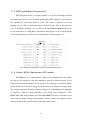
The IEEE released in 1994 the IEEE 1284 standard which includes the
specifications for EPP and ECP devices that are needed to fulfill in order to make
them work. Most of the computers auto-detect the working mode. Tables 1.1 and
1.2 show the pinout description of EPP and ECP respectively.
Pin
1
2
3
4
5
6
7
8
9
EPP Signal Pin
Write
10
Data 0
11
Data 1
12
Data 2
13
Data 3
14
Data 4
15
Data 5
16
Data 6
17
Data 7
18
EPP Signal
Pin
Interrupt
Wait
Spare
Spare
Data Strobe
Spare
Reset
Address Strobe
Ground
19
20
21
22
23
24
25
EPP Signal
Ground
Ground
Ground
Ground
Ground
Ground
Ground
Table 1.1. EPP pinout description
Pin
1
2
3
4
5
6
7
ECP Signal
HostCLK
Data 0
Data 1
Data 2
Data 3
Data 4
Data 5
Pin
10
11
12
13
14
15
16
ECP Signal
PeriphCLK
PeriphACK
nACK reverse
X-Flag
Host ACK
PeriphRequest
nReverseRequest
8
Data 6
17
1284 Active
9
Data 7
18
Ground
Pin
19
20
21
22
23
24
25
ECP Signal
Ground
Ground
Ground
Ground
Ground
Ground
Ground
Table 1.2. ECP pinout description
One important characteristic of the parallel port is that it uses the connector
called DB-25. This connector (illustrated in figure 1.1) consists of 25 pins shaped in
a “D” form. The computers generally include a female connector.
Fig. 1.1 DB-25 connector (Courtesy of HowStuffWorks Inc.)
1.1.3 Light Emitting Diodes
To describe the Light Emitting Diode (LED), first some background of the
diode working principles must be provided. The diode is a semiconductor device (it
6
is able to transport electric current), typically made of aluminum-gallium-arsenide
(AlGaAs). To make the device working, the pure material should be “doped”, a
method which consists of adding impurities, so the material can be better in
conducting the current. This state is achieved by either adding “holes” or extra
electrons to the material.
When the material has extra electrons, it is said that has a negative charge,
therefore it is called “N-type”. On the other hand, when the material has extra holes,
the charge is positive, therefore it is called “P-type” material. The diode task is then
to compromise two sections of N-type and P-type material bonded together with
electrodes on each end. This causes the current to flow in only one direction. When
no voltage is applied to the diode, no current flows and therefore the holes of the Ptype material are filled with the extra electrons of the N-type material. The way to
connect the diode to work properly is illustrated in figure 1.2, where it can be seen
that the negative part of the power supply is connected to the N-type material, and
the same is done with the positive part of the power supply and the P-type zone.
Fig. 1.2 Correct connection of a diode (Courtesy of HowStuffWorks Inc.)
The light on a diode is produced when its atoms release photons as a
source of energy. The photons are released because of the change of conduction
band from the electrons. As it was explained before, the electrons go from the Ntype material into the P-type one. This movements cause energy to be released, and
this energy can be photons. All the diodes release photons, but the human eye
cannot see all of them, because this depends on the different photon frequency.
7
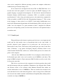
The Visible LED (VLED) is the kind that is formed with materials where
the material gap is wide enough to determine a certain photon frequency, and
therefore, can have different colors as well. Something important is also that LED’s
are constructed in a certain way that the most number of photons are released. Also,
the LED encapsulation is constructed in a specific way, so the produced light is
oriented to a certain place, as figure 1.3 shows in a diagram.
Fig. 1.3 LED construction diagram (Courtesy of HowStuffWorks Inc.)
When a LED is forward-biased, the electrons that cross the PN material
junction from the n-type material and travel to the holes of the p-type one. When the
recombination takes place, the electrons that have recombined release energy in the
form of light and heat. Electroluminescence is the process that describes when a
large exposed surface area on one layer of the semiconductor material permits the
photons to be emitted as visible light.
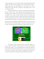
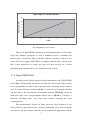
Gallium Arsenide (GaAs) LEDs project infrared radiation while Gallium
Arsenide Phosphide (GaAsP) show yellow or red light and Gallium Phosphide
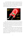
(GaP) produce red or green light. LEDs emit light as a reaction to an applied
forward current. The amount of light output is directly proportional to the forward
current as figure 1.4 can illustrate. Infrared LEDs can be used in optical coupling
applications, often in cooperation with fiber optics, as well as remote control
applications for short distances.
8
Light output vs. Forward Current
120
Radiated Light (mW)
100
80
60
40
20
0
0
2
4
6
8
10
If (m A)
Fig. 1.4 Output light vs. Forward current
The way to apply IR LED technology to telecommunications can be in short
range and computer peripherals as well as hand-held devices. Commonly the
Infrared Data Association (IrDA) publishes different standards related to this
matter. The way to apply an IR LED is by emitting radiation into a narrow beam
that is then modulated (to encode the data) and then received on a silicon
photodiode that transforms the received data into electric current.
1.1.4 Atmel AT89C51ED2
According to the datasheet provided by the manufacturer, the AT89C51ED2
has 64-Kbyte Flash memory that can be used both for code and data. This memory
can be programmed in either serial or parallel mode, depending on the software
used. It also has 256 bytes of internal RAM, a 9-source 4-level interrupt controller
and three timers. The total amount of nonvolatile memory (EEPROM) consists of
2048 bytes. Also, it has a programmable counter array, a XRAM or 1792 bytes, a
Hardware Watchdog timer, and some other features regarding the serial
communications.
The microcontroller design can bring down the clock frequency to any
value, which is a good characteristic so power consumption can be reduced without
any data loss. All these features make the device powerful for applications with the
9
12
need of pulse width modulation, high frequency input/output and counting
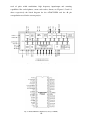
capabilities like corded phones, smart card readers, alarms, etc. Figures 1.5 and 1.6
show respectively the block diagram for the AT89C51ED2 and the 40 pin
encapsulation used for the current project.
Fig. 1.5 AT89C51 Block Diagram (Courtesy of ATMEL)
Fig. 1.6 AT89C51ED2 Pin Configuration (Courtesy of ATMEL)
10
1.1.5 EDE Parallel/Serial Transceiver IC
This integrated circuit, as it name explains, is a device that changes parallel
data into serial and vice versa. It works with standard TTL voltage (5 volts) and has
the capability of converting words of 8 bits. The circuit is intended to be used
logging data to a PC or control hardware via the PC ports (like in this project’s
case). It is BAUD selectable, so it can operate at both 2400 and 9600 BAUD speed.
It can work either as a half-duplex transmitter, half-duplex receiver or half-duplex
bi-directional transceiver. The circuit encapsulation is shown in figure 1.7.
Fig. 1.7 EDE300 Pin Configuration (Courtesy of ELAB Digital Engineering Inc.)
1.1.6 Hitachi LM016L Alphanumeric LCD module
The LM016L is an alphanumeric Liquid Crystal Module that can display
two lines of 16 characters each. No backlight is provided with this model. It uses
Super Twisted Nematic Liquid Crystal, and the way of driving is via passive matrix.
It only needs one +5V power supply and the characters are displayed in gray color.
The 14 pins needed for control are shown in figure 1.8. Something that is important
to mention is that the main controller is the Large Scale Integrated
(LSI)
HD44780U, built in the module. Also the HD44100R LCD driver is mounted as an
aid for the electronic driving of the module. A more detailed description of these
driving circuits will be provided in the following sub-sections.
11
Fig. 1.8 Pin connection for the LM016L module (Courtesy of Hitachi)
1.1.7 HD44780U LCD Controller/Driver
The HD44780U is a dot-matrix liquid crystal display controller and driver
Large Scale Integration circuit able to display alphanumerics, Japanese kana
characters and symbols. It can drive a dot-matrix either under 4 or 8 bit logic. One
single chip can display up to one 8-character line or two 8-character lines. Its
character generator ROM can generate up to 208 5x8 dot character fonts and 32
5x10 dot character fonts for a total of 240 different character fonts. It uses a low
power supply TTL compatible, which makes it suitable for battery powered
applications and low power consumption. Some of the product features are:
•
•
•
•
•
•
•
•
5x 8 and 5x10 dot matrix possible
Low power operation support:
---2.7 to 5.5V
Wide range of liquid crystal display driver power
---3.0 to 11V
Liquid crystal drive waveform
--- A (One line frequency AC waveform)
Correspond to high speed MPU bus interface
--- 2 MHz (when VCC = 5V)
4-bit or 8-bit MPU interface enabled
80x 8-bit display RAM (80 characters max.)
9,920-bit character generator ROM for a total of 240
character fonts
--- 208 character fonts (5x8 dot)
12
--- 32 character fonts (5x10 dot)
• 64x 8-bit character generator RAM
--- 8 character fonts (5 ´ 8 dot)
--- 4 character fonts (5 ´ 10 dot)
• 16-common x 40-segment liquid crystal display driver
• Programmable duty cycles
--- 1/8 for one line of 5x8 dots with cursor
--- 1/11 for one line of 5x10 dots with cursor
--- 1/16 for two lines of 5x8 dots with cursor
• Wide range of instruction functions:
--- Display clear, cursor home, display on/off, cursor
on/off, display character blink, cursor
shift, display shift
• Pin function compatibility with HD44780S
• Automatic reset circuit that initializes the
controller/driver after power on
• Internal oscillator with external resistors
• Low power consumption
The block diagram for the HD44780U is shown in figure 1.8 below.
Fig. 1.8 HD44780U Block Diagram (Courtesy of Hitachi)
13
As it was explained in the description, this circuit controls the dot matrix
providing the necessary driving waveforms for the Liquid Crystal. This signals
consist of 16 common signal drivers and 40 segment signal drivers. Something that
is interesting for the scope of this project is the use of the Character generator ROM
(CGROM). The CGROM generates the character patterns from 8-bit codes store a
table that corresponds to the ASCII table.
1.1.8 HD44100R LCD Driver with 40-channel outputs
This integrated driving circuit is also mounted on the LM016L LCD
module, and it provides an aid to the HD44780U. The device has two sets of 20-bit
bi-directional shift registers, 20 data latch flip-flops (for data storage) and 20 LCD
driver circuits. The HD44780U sends the serial data which is then converted into
parallel and the supplied to the display in the proper waverforms. It is a general
liquid crystal display driver that can drive static or dynamic liquid crystal and can
be applied as a common or segment driver. The device features are:
• Liquid crystal display driver with serial/parallel
conversion function
• Serial transfer facilitates board design
• Capable of interfacing to liquid crystal display
controllers: HD43160AH, LCTC (HD61830/61830B),
LCD-II
(HD44780S,
HD44780U),
LCD-IIA
(HD66780), LCD-II /E (HD66702), LCD-III
(HD44790), HD66710
• 40 internal liquid crystal display drivers
• Internal serial/parallel conversion circuits:
--- 20-bit shift register x2
--- 20-bit data latch x2
• Display bias: Static to 1/5
• Power supply:
--- Internal logic: Vcc=2.7 to 5.5V
--- Liquid crystal display driver circuit: VCC-VEE=3 to
13V
• Separation of internal logic from liquid crystal display
driver circuit increases applicable controllers and liquid
crystal types
• CMOS process
Figure 1.9 shows the block diagram for the device.
14
Fig. 1.9 Block Diagram for HD44100R (Courtesy of Hitachi)
As it can be seen from the previous description, this driver works in good
company with the HD44780U by providing the proper signals needed to drive the
liquid crystal segments. The group of segments is what creates one complete
character.
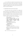
1.2
Project’s block diagram
The project consists of two main blocks. The first one covers the part that
captures and sends the infrared data, and the second one includes the receiving
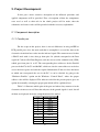
circuit and the LCD module. Figures 1.10 and 1.11 refer to the block diagram of
each one of the blocks.
Fig. 1.10 Block diagram of IR sending
15
Fig 1.11 Block Diagram for IR receive stage
Both blocks complement each other. In the upcoming section, an
explanation of how each one of the blocks interact with each other, as well, as a
description of which devices belong to each one will be provided.
16
2. Project Development
In this part a more extensive description of the followed procedure and
applied components will be provided. First a description of how the components
were used as well as their role in the whole project will be made, then the
schematics and source codes will be provided with the necessary explanation.
2.1 Component description
2.1.1 Parallel port
For the scope of this project, there is no real difference in using an EPP or
ECP parallel port, since the main task that it accomplish is to send the data to the
electronic circuit that later codes into the infrared signal. The connector used is then
a DB-25 male with 8 wires that go from pins 2-9 (which correspond to the Data
signals 0-7 often called Data Register) and one wire used for common node (GND)
which goes from pins 18 to 25. The corresponding base addresses for the Parallel
port can be 0x278, 0x378 and 0x3BC, which are also the same addresses needed to
access the data register and send the required information. If the user does not know
to which one corresponds the one in the PC, it can be checked by going to the
“Hardware Profiles” option on the Windows “Control Panel”, where the proper
address value will be displayed. The software coded for the present project gives an
option for manually selecting the proper port which will be explained later.
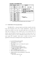
Table 2.1 illustrates which pins of the port and where they connect to in the
electronic circuit were used. Note that only one of the ground signals is used, but all
of them are displayed for better comprehension of the model.
Pin
1
2
3
4
5
6
7
Parallel port signal
NC
Data 0
Data 1
Data 2
Data 3
Data 4
Data 5
8
Data 6
9
10
11
Data 7
NC
NC
17
NC
NC
NC
NC
NC
NC
Ground*
Ground*
Ground*
Ground*
Ground*
Ground*
Ground*
Ground*
12
13
14
15
16
17
18
19
20
21
22
23
24
25
Table 2.1 Pins used in parallel port
2.1.2 EDE 300 and Infrared Light Emitting Diode
The EDE 300 integrated circuit is very important for the proper function of
the project, since it is the one that takes charge of coding the parallel data received
from the PC’s port and then converts to a serial data. After the input parallel data
has been received, it is send as a serial data to a power stage part before it is send
via the Infrared LED to the other part of the circuit. Since the transmission speed is
not a critical matter for this project, the maximum data sending transfer rate was
selected (9600 bps). The circuit has the option of both 9600 and 2400 bps. Two
EDE 300 circuits are used in the project, one to serialize the data received from the
parallel port and the second one that does the opposite, capturing the data from the
IR receiver and sending it as a parallel word to the microcontroller.
Both circuits are configured to work in Local Control Mode, which means
that they are constantly scanning for new data to be converted either to serial or
parallel, depending on the side of the IR transmission the circuit is working. This
means that the MODE pin (third) is set to a logic 0 (zero) or low voltage. The baud
rate, as explained earlier is set to 9600 (None parity, 8 bits, 1 stop bit) by placing
pin number 2 (Baud Rate) to a logic 1 (one) or high voltage. This two signals are set
equally to both circuits. The signal that changes from one to another is the one of
the first pin (Data Direction/Latch) which refers of the data flow direction. This
means, that for the circuit that receives the parallel data and converts to serial, the
pin should be connected to logic 0 (zero) and viceversa. As it is clearly stated in the
datasheet, the connections should be made taking special care not to send data to
18
the output terminals, depending on each case. Table 2.2 summarizes the pin
configuration for each one of the two EDE 300 used.
Pin name (number)
Data direction/latch (1)
Baud Rate (2)
Mode (3)
+5V in (4)
GND (5)
Data I/O 0 (6)
Data I/O 1 (7)
Data I/O 2 (8)
Data I/O 3 (9)
Data I/O 4 (10)
Data I/O 5 (11)
Data I/O 6 (12)
Data I/O 7 (13)
+5V in (14)
Osc2
Osc1
Serial Rcv
Serial Xmit
Parallel to serial
Low (0)
High (1)
Low (0)
High (1)
Low (0)
Input
Input
Input
Input
Input
Input
Input
Input
NC
4MHz OSC
4MHz OSC
NC
Output
Serial to parallel
High (1)
High (1)
Low (0)
High (1)
Low (0)
Output
Output
Output
Output
Output
Output
Output
Output
NC
4MHz OSC
4MHz OSC
Input
NC
Table 2.2 EDE 300 circuits signals
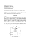
2.1.3 Power Stage
This is an important part of the circuit added to enhance the performance of
the infrared transmission. The output from the EDE 300 might not be enough to
have an strong signal that will reach the other side. Also, demanding too much
current can cause malfunction, that is a strong reason to add this power stage. This
is a very basic power stage provided by one NPN bipolar general purpose transistor
BC549. Figure 2.1 shows the simulation of the power stage, assuming that 25mA
(the maximum rate) is provided by the EDE300. The resistors were calculated so
the transistor current does not exceed the 100mA. Also, in the simulation, two
amperimeters are placed to measure the electric current flowing from the interesting
points.
19
Fig. 2.1 Circuit simulation of the power stage
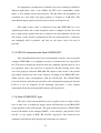
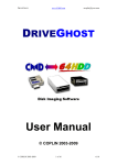
2.1.4 IR reception
On the other circuit, the first component needed is the infrared receptor. The
device used for this purpose is the Everlight Miniature Type IRM-8601S, shown in
figure 2.2. It consists of a photodiode with an integrated circuit encapsulated in a
metal case, which makes it resistant to different noises and ambient light.
Fig. 2.2 Picture of IRM-8601S
20
It is important to mention that it consumes low power, making it reliable for
different applications. Also, it has CMOS and TTL levels compatibility, which
makes it very suitable for the current project. The pin diode and preamplifier are
assembled on a lead frame, the epoxy package is designed as an IR filter. The
demodulated output signal can directly be decoded by a microprocessor
The output of this sensor is connected to the other EDE 300. As it was
explained previously, this second integrated circuit is configured to have the serial
pin as input and the parallel data pins as output to the microcontroller. In the next
sub-section, a more detailed explanation of how the microcontroller is connected
and configured will be provided, and later on, the source codes will also be
provided.
2.1.5 EDE 300 interaction with Atmel AT89C51ED2
The communication between the microcontroller and the serial to parallel
configured EDE 300 is very important, because it determines the last stage before
the LCD starts to display the characters that were originally typed by the user. As it
was explained earlier, the serial data is detected by the IR receiving device, then
sent to the properly connected EDE 300. The output of this circuit is the parallel
word which contains the code of the character according to the HD44780U table,
which also has some correspondence with the ASCII table. The AT89C51ED2
reads the character from the port and then sends it through the output pins into the
LCD so it can be displayed. In the following sub-section, a more detailed
explanation of how the microcontroller behaves will be provided.
2.1.6 Atmel AT89C51ED2 logic
The tasks of this microcontroller in the reception circuit are quite crucial,
since it takes care of sending the proper signals and characters to the HD44780U
circuit mounted on the LCD module. The ports connected from the AT89C51ED2
to the LCD module are the complete PORT 1 as the data byte, and pins P3.5, P3.6
and P3.7 as the signals of R/W, RS and EN respectively. The section for the
schematics will illustrate how the physical connections are achieved.
21
The first task that it performs after powering up is to initialize the display,
sending the corresponding signals as the HD44780U datasheet explains, and which
are shown in figure 2.3. This routine is performed to ensure that the proper
initialization is done according to the supply voltage. First on DB4 or DB5 a high
signal is sent and a wait of more than 4.1 milliseconds should be done. After
waiting, the same signal is sent again, but after the wait should be of more than 100
microseconds. After that, the last initialization steps (explained in the next
paragraph) are performed.
Fig. 2.3 LCD Routine steps
As it will be explained later on the “source codes” section, the
AT89C51ED2 is constantly checking the input port connected to the EDE300. This
is PORT 0, consisting on the 8 bits from pin 0.0 to pin 0.7. According to the logic
of the program, while no character is being sent, a value of zero (all the pins will be
in low voltage) will be read, causing the microcontroller to keep scanning that port
22
until a different value is received. This different should be the character code, and
therefore it will send the appropriate signals for the character to be displayed. The
sequence is first to send a high voltage to RS signal, then move the read byte code
to the output port (Port 1) and then set the EN signal, so the display executes the
write data command. After, as it is explained in the HD44780U datasheet, the LCD
sends a busy signal on pin DB7, which is checked by the microntroller with a
timeout of 256 times. If a reset signal is applied to the microcontroller, then the
LCD will be cleared, because it is configured to work like that from the
initialization routine.
2.2 Schematics
The present subsection will describe mainly with images how the physical
and electrical connections were made on the whole project.
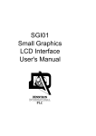
2.2.1 Infrared sending circuit
The part of the project that takes care of the parallel port reception and
infrared encoding is shown on figure 2.4. It can be seen how everything starts from
the DB-25 connector which corresponds to the PC port. The data pins (2-9) are
connected to the inputs of the EDE300 D0-D7. As it was explained earlier, this
EDE300 is configured as a parallel to serial transceiver, therefore the Dir/Latch pin
1 is connected to a low voltage input.
23
Fig. 2.4 Infrared encoding circuit
The crystal is also placed in the appropriate pins of the integrated circuit so
it works correctly. It is important to see how all the stages are placed together,
including the power stage where the infrared transmission LED is driven by the
transistor’s collector current in order to enhance the range of the device.
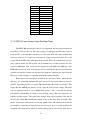
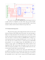
2.2.2 Infrared receiving circuit
This part of the system is more complex than the previous one due to the
inclusion of both the AT89C51ED2 and the LCD module, since they both require a
higher level of logic abstraction. The circuit layout can be seen in figure 2.5. The
data flow starts from the infrared reception unit that captures the data sent from the
other circuit. Then it is transferred serially to the EDE300 which is configured as a
serial-to-parallel transceiver by having the Dir/Latch pin 1 set to Vcc (+5V). This
device then takes care of sending the data as a parallel word to the AT89C51ED2
microcontroller. As it was explained before, the AT89C51ED2 takes care of
sending the proper signals to the HD44780U LCD controller mounted on the
alphanumeric LCD. The fact that many LCD modules use this driver gives the
whole unit a big shot in portability, so in case a different module wants to be used,
it can be replaced and the whole system will still work.
Some details that are considered in the wiring of the AT89C51ED2 is that
the PSEN and the ALE pins are not connected since all the code is stored without
the use of any external device memory. Also the EA (enable) pin is set correctly as
the microntroller needs to work in order to operate the LCD module properly.
24
Finally it is important to mention that a push-button is added to the RST pin of the
device, in case the microcontroller is needed to be reset.
25
Fig. 2.5 Receiving circuit
26
2.3 Source code
The present subsection will provide the source codes used both for the user
interface in the computer and for the microcontroller. Then an explanation of the
different data manipulation will be provided as well as a user manual for the
program.
2.3.1 User interface code
The programming language for the user interface was C as it was mentioned
previously. The application is a windows console and it was compiled under
Microsoft Visual C++. Figure 2.6 describes the algorithm that was followed.
Fig. 2.6 User interface program algorithm
The code is shown next and an explanation of the different methods will be
provided afterwards.
27
/**************************************************************
The present program is used to capture characters from the
keyboard
and send them to the parallel port of a computer. It should be
compiled with Microsoft Visual C++.
For windows NT/2000/XP UserPort should be running along.
**************************************************************/
#include <conio.h>
#include <stdio.h>
#define LPT1 0x378 //888
#define LPT2 0x278 //632
#define LPT3 0x3BC //956
/***********************************************************
Method manda to send the character to the parallel port, receives
both the port number and the character to be sent as parameters
************************************************************/
void manda (int port,char dat)
{
_outp(port, dat);
}
/**************************************************************
Method to create a time delay
**************************************************************/
void delay (void)
{
int i,j;
for(i=0;i<10000;i++)
{
for(j=1000;j>=0;j--);
}
for(i=0;i<10000;i++)
{
for(j=1000;j>=0;j--);
}
}
/***************************************************************
Method recibe that sets the correct port address (according to
the user
input), received the character(s) to be sent and determines the
flow control of the program until it is finished.
***************************************************************/
void recibe (void)
{
char dato='A',op,bas;
int puerto;
while((op!='1')&&(op!='2')&&(op!='3')) //Validates the LPT
port
{
printf("\n\nPlease define define which parallel port be
used (1,2,3)-> ");
scanf("%c%c", &op,&bas);
if(op=='1')
{
puerto=LPT1;
printf("\n\nPort LPT1 0x378 selected \n\n");
}
else
if(op=='2')
{
puerto=LPT2;
printf("\n\nPort LPT2 0x278 selected
\n\n");
}
else
28
if(op=='3')
{
puerto=LPT3;
printf("\n\nPort LPT3 0x3BC
selected \n\n");
}
else
printf("\nINVALID SELECTION, PLESE
TRY AGAIN!");
}
while(dato!=10)
{
printf("\nNext character to send (Carriage Return char
to terminate)--> ");
scanf("%c%c", &dato,&bas); //Character is received
if(dato!=10) //Check if Carriage Return was not
received
{
manda(puerto,dato); //Send character to the port
delay();
manda(puerto,0);
printf("\nCharacter %c sent succesfully\n",
dato);
}
else //If Carriage Return was received, the program is
finished
{
printf("\n\nThanks for using this software!!!");
printf("\n\nPress any key to finish\n");
getch();
}
}
}
/*Method presenta that displays the banner of the program*/
void presenta (void)
{
printf("\n***************************************************
****************");
printf("\n***************************************************
****************");
printf("\n***************************CharRcv.exe****************************");
printf("\n\tWelcome to the program that will send data to
LCD");
printf("\n\tThe way this program works is by prompting the
user");
printf("\n\tto type in the desired character, then it will be
sent");
printf("\n\tto the LCD connected in the remote location.");
printf("\n\tThe program will terminate when Carriage Return
is sent as character");
printf("\n\tProgrammed by Hector Jaramillo Cantu, Hogskolan
Dalarna 2006");
printf("\n***************************************************
****************");
printf("\n***************************************************
****************");
recibe();
}
/*Main Method */
void main (void)
{
presenta();
}
29
Main Method
This method is included as an essential part of every C and C++ code. It
does not receive any variables and it also does not return anything as it is declared
as a “void”. It contains only one code line that calls the “presenta” method.
Presenta Method
This method takes care of displaying some basic information about the
program in the form of a banner. It does not receive or send any parameters, since
its main task is to display only. The final line calls the “recibe” method.
Recibe Method
This is a very important method for the correct function of the whole
program, since it takes care of asking and setting for the proper port address that
will be used as well as receiving and validating the characters from the user that
will be sent. It does not receive any parameters and it does not return anything
either.
It uses 4 local variables. The first 3 (dato, op & bas) are characters and the
last one (puerto) is an integer value. Here is a short description of each one of the
variables and what are they used for:
•
dato: It is initialized with the character ‘A’ so the character receiving
cycle can start. This variable stores the character typed by the user.
•
op: This variable stores the value of the parallel port that will be
used through the whole program.
•
bas: This is a garbage collector character used to store the carriage
return key that is pressed after an option from the program has been
selected.
•
puerto: This variable stores the value of the selected port and once it
is set is not changed until the program is terminated.
The start of the program is by validating that either choices 1, 2 or 3 are
selected, each one corresponding to the address of a parallel port. If something
invalid is typed (like a character or a higher number) the program will send a
30
notification message and then prompt again for a valid option until this has been
received. When this happens, a confirmation banner will be shown on the screen.
The next part of the program consists of prompting the user for a character
to be sent to the port. This prompt will go on until a carriage return (ASCII code A
in hex) is received, which will terminate the program. When a character is received,
the program calls the “manda” method (which takes care of sending the characters
to the port) providing the parameters of the character and the port number, stored in
the dato and puerto variables respectively. After this is done, the “delay” method is
called and then the “manda” method is called again, this time sending a value of 0
(zero) instead of the dato variable. This is performed because according to program
logic, after a character is sent, a signal of zero is sent to let the microcontroller on
the other side know that no new character has been typed. Finally, a banner that
informs the success in sending the character is displayed on screen, and the cycle
for character receiving starts again. When the carriage return character is received a
banner indicates that the program is finished and the “getch” instruction is
performed so the user can type any key to close the window.
Delay Method
The task of this method is to create a time delay for the data to be sent to the
parallel port the to the circuit. It is used between the sending of a character and the
sending of a zero through the parallel port, so the EDE300 circuit has enough time
to do its transceiver job. This consists of two sets of nested “for” instructions. It
does not receive or return any parameters.
Manda Method
This method consists of one instruction only which is “_outp”. This
instruction is very important because it performs the data transfer to the parallel
port. This instruction receives as parameters the address of the port as well as the
data that is going to be sent. The method does not return any value, but it receives
the parameters of the port and the data as the integer variable port and the character
variable dat respectively.
31
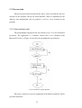
2.3.2 AT89C51ED2 code
The language used to program the microcontroller was assembly language
according to the instruction set provided by the manufacturer. According to the
logic of the assembly language, it does not contain different methods, but tags that
lead to instructions. The algorithm used for the program is shown in figure 2.7.
Fig. 2.7 AT89C51ED2 program algorithm
It was mentioned earlier that Port 1 is used as the data communications port
to the LCD, therefore, the mnemonic of DB0-DB7 was assigned to each one of the
pins as well as the whole port is called DATO to be managed through the whole
program. The signals of RW, RS and EN were assigned to pin 3.5, pin 3.6 and pin
3.7 respectively. Finally the mnemonic of READ was given to Port 0 which takes
care of receiving the parallel data from the EDE300 before it is sent to the LCD
module. The whole program code is shown below and after an explanation of the
instructions sorted by tag is provided.
32
;Program for the Atmel AT89C51ED2 used to initialize and
;drive LCD, receive a parallel byte and send as a character
;to LCD
;Coded by Héctor Jaramillo Cantú for the Master Thesis in
;Display Technology
;Högskolan Dalarna, Borlänge Sweden 2006
DB0 EQU P1.0
DB1 EQU P1.1
DB2 EQU P1.2
DB3 EQU P1.3
DB4 EQU P1.4
DB5 EQU P1.5
DB6 EQU P1.6
DB7 EQU P1.7
EN EQU P3.7
RS EQU P3.6
RW EQU P3.5
DATO EQU P1
READ EQU P0
org 0
MAIN:
CALL INIT_LCD
CALL CLEAR_LCD
JMP STDBY
STDBY:
MOV A,READ
JZ STDBY
CALL WRITE_TEXT
MOV A,#0h
JMP STDBY
WAIT_LCD:
MOV R0,#0FFh
WAIT_1:
CLR EN
CLR RS
SETB RW
MOV DATO,#0FFh
SETB EN
MOV A,DATO
JNB ACC.7,SALIR
DJNZ R0, WAIT_1
SALIR:
CLR EN
CLR RW
RET
INIT_LCD:
CLR RS
MOV DATO,#38h
SETB EN
CLR EN
LCALL WAIT_LCD
CLR RS
MOV DATO,#0Eh
SETB EN
CLR EN
LCALL WAIT_LCD
CLR RS
MOV DATO,#06h
SETB EN
CLR EN
LCALL WAIT_LCD
33
RET
CLEAR_LCD:
CLR RS
MOV DATO,#01h
SETB EN
CLR EN
LCALL WAIT_LCD
RET
WRITE_TEXT:
SETB RS
MOV DATO,A
SETB EN
CLR EN
LCALL WAIT_LCD
RET
END
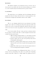
Main
This is where program starts. The tag takes care of calling the sub-methods
of INIT_LCD and CLEAR_LCD and then transfers the control of the program to
the STDBY tag.
Stdby
The instructions that follow this tag are performed in a cycle, since the main
task of the program after the LCD has been initialized is to wait for a character to be
received and then to send it to the module. The first instruction (MOV A,READ)
reads the data from the READ port to the Accumulator. Then this data is compared
with zero, so in case a zero was received (JZ STDBY), the port will be checked
again in a cycle. This cycle is broken when a value different from zero is received,
so the program calls the WRITE_TEXT routine (explained later). Then the value of
zero is placed again on the Accumulator (MOV A,#0h) and the cycle to wait for a
character starts again (JMP STDBY).
Wait_lcd
This subroutine is important because as it is explained in the HD44780U
datasheet, when the LCD module is done with an instruction, a signal will be sent
on the DB7 pin. The current subset of instructions takes care of check for that
34
signal, so the next LCD instruction can be performed. It is important to mention
also that a timeout of 255 tries is added, in case the signal never comes, as a way of
preventing a potential infinite loop that would cause the malfunction of the
program.
The first instruction (MOV R0,#0FFh) sets the timeout of 255 using
Register 0 as the counter for the number of tries. Then a tag of WAIT_1 is placed as
a sub-loop that will take place for the countdown. The next 3 instructions (CLR EN,
CLR RS and SETB RW) send the appropriate signals to the LCD to let it know that
the instruction has been performed. After this is done, the whole data bus is set to
high voltage in all pins for electronic reasons, since when a zero is received, the
signal on that pin will go to a low voltage. Then the port is read again (MOV
A,DATO) and the data pin 7 is checked (JNB ACC.7,SALIR). If the pin is still in
high voltage then the value of Register 0 is decremented and the cycle is done again
(DJNZ R0,WAIT_1). After the previous cycle is done 255 times or the low signal is
received on pin 7, whatever happens first, the pins for EN and RW are cleared again
and the subroutine returns the control to the previous set of instructions that called
it.
Init_lcd
This is where program starts. The tag takes care of calling the sub-methods
of INIT_LCD and CLEAR_LCD and then transfers the control of the program to
the STDBY tag.
Clear_lcd
This method follows the instructions provided in the HD44780U manual to
clear the data on the display. First the instruction of 01H is sent through the data
bus. Then the EN (enable) pin is manipulated (turned on and off) so the instruction
is executed. After, the “WAIT_LCD” routine is called to wait for the LCD to finish
processing the instruction.
35
Write_text
In this routine, the instructions to write the data to the LCD are followed as
the datasheet for HD44780U indicate. First the RS (Register Select) is set on, then
the received data from the EDE 300 is sent to the data bus. After, the EN (enable)
pin is manipulated (turned on and off) and the wait routine is called before it returns
the control to the method that called originally.
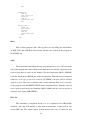
2.4 User Manual for the software
The way to start the program is by running the Char-Rcv.exe executable file
provided with the system. The first screen will display a banner shown on figure 2.8
that introduces the user to the program. On this initial screen the user is prompted to
choose the LPT (Parallel) port that will be used to transfer the data.
Fig. 2.8 Char-Rcv initial screen
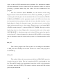
Notice that the program can only accept options 1, 2 or 3. If something else
is typed, the program will notify the user as it can be seen on figure 2.9 and then it
will prompt for a valid option. There is no timeout or maximum number of tries, so
if the software must be stopped, the window should be closed.
36
Fig. 2.9 Invalid selection banner
When a valid option has been selected, the program also confirms both the
address and the port number that will be used through the whole program. It is
important to notice that once this port has been selected, it cannot be changed until
the program is closed and started again. Figure 2.10 shows the example of a valid
choice and how the program confirms the port address.
Fig. 2.10 Selection of parallel port
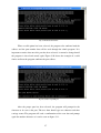
After the proper port has been selected, the program will prompt for the
character to be sent to the port. The user then should type one character and then
carriage return. The program will send a confirmation of the sent data and prompt
again for another character as it can be seen on figure 2.11.
37
Fig. 2.11 Character sending and confirmation
The program will go on asking for characters to be sent to the port until the
character of carriage return is sent, which will indicate the program to terminate.
This means that when the program requests for a character, the user should hit two
times in a row the “enter” key. When this is done, a banner explaining the ending of
the program will appear and then one last key press will be requested to close the
window. Figure 2.12 illustrates this procedure.
Fig. 2.12 Program ending.
38
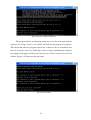
2.4.1 Special considerations
The present program is intended to work on Microsoft Windows operative
system based personal computers. If the computer is running Windows 95/98, the
program will work without any problems at all. When a version of Windows
NT/2000/XP runs the program an error is produced (shown in figure 2.13), because
these are secure operative systems that do not allow the access to memory locations
so easily. Many workarounds for this issue have been proposed. The one used (and
tested) for the present project is the use of the “UserPort” program. Userport is a
kernel mode driver for Windows NT/2000 that gives access to the users to the I/O
ports. With this, the direct hardware access from an executable file can be done just
like under a Windows 98 enviroment. The driver can be used for the following
purposes:
• To run software on Windows NT/2000 that normally only runs
on Windows 95/98/ME.
• To easily access hardware like the parallel port and other I/O
ports
Fig. 2.13 Error message
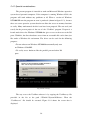
The way to use the UserPort software is by copying the UserPort.sys file
provided in the kit to the path %Windir%\System32\Drivers. Then the
“UserPort.exe” file should be executed. Figure 2.14 shows the screen that is
displayed.
39
Fig. 2.14 UserPort initial screen
After UserPort is initialized, a range of user addresses must be provided. For
the scope of this project, the memory addresses are 0x0278, 0x0378 and 0x03BC
corresponding to each one of the possible parallel ports in a computer. Two options
can be followed now. The first one is to open all the range of port addresses from
0x0277 to 0x03BD which will cover even more than the needed addresses. For
security reasons, it is recommended just to add the ranges of the known ports, being
them 0x0277-0x0279, 0x0377-0x0379 and 0x03BB-0x03BD as it is shown in
figure 2.15.
Fig. 2.15 Adding the addresses to UserPort
After the proper addresses have been established, the program should be
started by clicking on the “start” button. When the program is running, the software
created for this project will run correctly.
40
3. Results
For the final construction of the whole device, the whole project was built in
each one of its different modules. The main purpose of doing it by layers was to be
able to isolate each one of them in case any problems or wrong design should be
found and be able to correct, without affecting the project as a whole unit.
As each one of the parts were tested, the results were achieved by stages. A
whole idea of the system was sketched in the beginning, but as the design was
started to be made, the chunks were modified in order to proper function. The
project was divided in different blocks (as this project report is) so the particular
analysis of the modules could be analyzed individually.
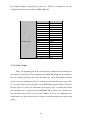
3.1 User interface program
First the user interface C program was created. Different tests were done
and at the end the best was to use the Microsoft Visual C++ compiler because of its
friendly interface and easy way to handle. Also, the way to handle port access was
easy and the debugging interface was useful to identify the former errors and
warnings incode. A debug was ran many times to ensure the programs robustness
before it was tested with the wiring cables. First just a series of LEDs were used to
ensure that the correct data was sent through the proper parallel port, being this part
successful.
3.2 Power stage
The second part consisted on testing the power stage. In the electronics lab
the proper current was applied to the transistor and to the IR LED ensuring that the
proper and needed current was flowing. This was correctly done and the chosen
resistors worked good as well. As a second part of this test, the IR receiver was
tested parallel, since it was receiving the signals from the encoding IR LED. An
Oscilloscope was able to determine that the proper signals were being received.
3.3 AT89C51ED2 debugging
After the previous tests were accomplished, the code for the microcontroller
was developed. The final approach was to achieve an Intel HEX file in order to be
able to put the set of instructions into the chip. The compiler used was the student
41
version of Keil uVision3. With this compiler, also different debugs to simulate the
Input and Output data were performed. In the end the HEX file was created and
programmed into de AT89C51ED2 with the proper device.
3.4 Final assembly
The final stage was to wire all the components together. Test boards were
used with cable to wire everything as in the schematic and a 5 Volt power source
for each one of the parts, since it is the power needed to drive the circuits. There
were some problems encountered in the first approach (as expected) since some of
the boards were not wired correctly. Therefore, a multimeter was used in order to
follow each one of the cables until the problem was found and solved. After this
was fixed, the system was tested again, and it was almost fully functional, but there
was a small problem with the timing, coming from the user interface program.
Therefore, the “delay” method was modified in order to get an appropriate timing to
synchronize the whole unit.
42
4. Possible applications and challenges
The current project can have different applications that can go from toys to
computer peripherals to even devices that can help disabled people, depending on
the point of view. It covers different topics from C programming, to different fields
of electronics as well as the Liquid Crystal Display driving. The whole project is an
approach for what could be made into a more robust system. It provides the basis
for wireless communication that can be used in a single room.
One first challenge can be to use different ports from the computer, and be
able to connect to serial or even USB depending on which kind of computer is used.
Another challenge can be to extend the operative system menu not only to
Windows, but maybe to be able to use the whole system in a Macintosh or
UNIX/Linux system. This would require a complete remake of the user application
software. Maybe even another language rather than C/C++ can be used, but the
same logic should be followed in order to keep the rest of the project working.
Something that can also be taken care of is the enhance of the power stage of
the infrared led to enlarge the distance range that the controller can operate.
Something that can also be done would be to change the transmission medium, and
instead of using an IR LED use something else like Radio Frequency, microwaves
or some kind of telecommunications device such as TCP/IP, UDP or IPX. The add
of any of these options would drastically change the original design and logic of the
programs.
43
5. Conclusions
Many challenges were encountered during the develop of the current project.
First the original design had to be modified several times in order to correct
possible non-working situations and to correct the needed details in order to make
the system to work as planned and expected.
This project itself covers different areas focusing more on the electronics
driving of an LCD module and its interaction with different devices. In the present
times, there are a few devices that work as standalone. This means that most of the
time the systems integrate different technologies to be able to perform a certain
specific task. This project is a clear example of how the devices need to interact
together.
As it was mentioned earlier, this work just presents one possible way of
making this wireless communication possible. This means that different approaches
can be proposed as well as developing extra features for the system.
44
6. References
[1]
A brief history of parallel ports. Thaddeus Computing Inc. 2005. URL:
http://www.palmtoppaper.com/ptphtml/45/45c0000d.htm
[2]
C Programming Language. Wikipedia , the free encyclopedia. 14 May
2006. URL: http://en.wikipedia.org/wiki/C_programming_language
[3]
COLLINS, Peter J. Liquid Crystals. Princeton University Press. USA, 2002.
ISBN: 0-691-08672-9
[4]
EDE 300 Parallel/Serial Transceiver IC datasheet. E-LAB Digital
Engineering, Inc. USA, 1996
[5]
FLOYD, Thomas L. Electronic Devices. Merril Publishing Company. USA
1988. ISBN: 0-675-20883-1
[6]
FRANZON, Tomas. UserPort Documentation. 2001. Email:
[email protected]
[7]
HF44780U Dot Matrix Liquid Crystal Display Controller/Driver datasheet.
Hitachi Ltd. Japan, 1998
[8]
PEACOCK, Craig. Interfacing the Standard Parallel Port. Beyond Logic
webpage, June 15th 2005. URL:
http://www.beyondlogic.org/spp/parallel.htm
[9]
TYSON, Jeff. How Parallel Ports Work. How Stuff Works 1998-2006.
URL: http://computer.howstuffworks.com/parallel-port.htm
45