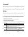
1
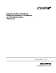
Horner Electric Metasys Interface Module Version 2.01 M/N 2MT3000 This user manual has been prepared by and appears courtesy of the Horner Electric Company. Should you have questions about either the contents of this manual or the Metasys Interface Module, please contact: Gary Bannister Horner Electric 317.639.4274, ext. 472 Instruction Manual HE-2MT Metasys is a registered trademark of Johnson Controls. GV3000 and VTAC 7 are trademarks of Rockwell Automation. Copyright Horner Electric Company 1997 2 Table of Contents 1.0 Introduction .......................................................................................................................................... 1-1 2.0 Mechanical/Electrical Description ........................................................................................................ 2-1 3.0 Installation Instructions ........................................................................................................................ 3-1 3.1 Installing the Metasys Interface Board in 1 - 5 HP and 7.5 - 10 HP Drives ....................................... 3-2 3.2 Installing the Metasys Interface Board in 15 - 60 HP Drives ............................................................. 3-7 3.3 Installing the Metasys Interface Board in 60 - 150 HP GV3000 Drives ............................................. 3-10 3.4 Installing the Metasys Interface Board in 75 - 150 HP VTAC 7 Drives ............................................. 3-13 3.5 Installing the Metasys Interface Board in 200 - 400 HP Drives .......................................................... 3-16 3.6 Connecting the GV3000 or VTAC 7 Drive to an N2 Communications Bus ....................................... 3-19 4.0 Data Types and Transfer Rates ............................................................................................................ 4-1 4.1 Input Data ........................................................................................................................................ 4-1 4.2 Output Data ...................................................................................................................................... 4-1 4.3 Input Transfer Enables ..................................................................................................................... 4-1 4.4 Output Transfer Enables ................................................................................................................... 4-2 4.5 I/O Update Enable Logic Summary ................................................................................................... 4-2 4.6 Tune/Config Update Synchronization ................................................................................................ 4-3 4.7 Parameter Processing Error Flag ....................................................................................................... 4-3 4.8 Data Retention Timing Requirements ............................................................................................... 4-3 4.9 Drive Ready Status Bit ...................................................................................................................... 4-4 Appendix A - Memory Map ........................................................................................................................ A-1 3 List of Figures Figure 2.1 - Metasys Port Pinout ..................................................................................................................... 2-1 Figure 3.1 - Metasys Interface Board Location in 1 - 5 HP Drives ................................................................... 3-3 Figure 3.2 - Metasys Interface Board Location in 7.5 - 10 HP Drives .............................................................. 3-4 Figure 3.3 - Metasys Interface Board Location in 15 - 25 HP Drives ............................................................... 3-8 Figure 3.4 - Metasys Interface Board Location in 25 - 60 HP Drives ............................................................... 3-8 Figure 3.5 - Metasys Interface Board Location in 75 - 150 HP VTAC 7 Drives ............................................... 3-14 Figure 3.6 - Metasys Interface Board Location in 200 - 400 HP Drives ........................................................... 3-17 Figure 3.7 - Example N2 Bus Layout .............................................................................................................. 3-19 List of Tables Table 3.1 - Locating the Appropriate Installation Procedure ........................................................................... 3-1 Table A.1 - Where To Find More Information on Specific Objects ................................................................. A-1 4 1.0 Introduction This manual describes the Horner Electric Metasys Interface module (M/N 2MT3000), which implements the Johnson Controls Metasys N2 protocol. The interface module is designed to allow VTAC 7 and GV3000 drives to be operated and monitored via the Metasys network. The Metasys Interface mounts below the Regulator board on the VTAC 7 and GV3000 drives and connects to the Regulator via a flexible ribbon cable. Power for the Metasys Interface comes from the drive through the Regulator. The drive is configured by using the keypad or the CS3000 software. The Metasys network can then operate and monitor the drive. More Information Before attempting to install and use the Metasys Interface, make sure you have read and understood the VTAC 7 or GV3000 instruction manual and any pertinent documentation for the Metasys N2 network from Johnson Controls. This instruction manual does not explain drive operation or Metasys network installation and programming. Basic Installation and Operation Steps This section describes how to install and operate the Metasys Interface. Chapter 3 in this instruction manual describes installing the module in more detail. This manual assumes that the Metasys network has already been installed and configured properly. 1. Install and wire the VTAC 7 or GV3000 drive. 2. Install the Metasys module in the drive. See chapter 3 for installation instructions. 3. Connect the Metasys module to the Metasys network. 4. Completely configure the VTAC 7 or GV3000 drive using the keypad or the CS3000 software. Make certain to set the following parameters correctly to allow the drive to communicate with the Metasys network. Parameter Number P.000 P.048 P.060 P.061 P.062 P.063 Parameter Name Control Source Volts/Hertz or Vector Regulation Network Drop Number Note: The network drop number is used to assign the N2 on the drive. Network Connection Type Option Port: Communication Loss Response Note: Before setting this parameter, see the GV3000 or VTAC 7 manual for the complete parameter description. Option Port: Network Reference Source Set to: OP (Option port) U-H (V/Hz control) 1-99 0 (Basic) 0 (IET Fault) 1 (Hold last reference) 2 (Terminal strip reference) 0 (Direct reference) Make sure to cycle power to the drive after configuring it for the configuration to take effect. 5. Configure the Metasys network to recognize the Metasys Interface module. 6. Refer to the memory map in Appendix A of this instruction manual for the objects accessible over the network. 5 7. If the drive will be controlled over the Metasys network, perform the following commands in the Metasys host to control the drive: a) Write the desired drive speed to analog output 1 (AO-1), Speed Reference. b) Write the desired drive direction to binary output 4 (BO-4), Forward/Reverse (default = forward). c) Write the desired maximum drive speed to analog output 3 (AO-3), Maximum Speed. d) Write the desired minimum drive speed to analog output 2 (AO-2), Minimum Speed. e) Write a value of 1 (one) to binary output 1 (BO-1), Start. The drive should run at the desired speed. Verify that the drive’s front panel display reads the same value as in analog input 1 (AI-1), Drive Speed Feedback. 6 2.0 Mechanical/Electrical Description The Metasys Interface board is a printed circuit board that mounts inside the VTAC 7 or GV3000 drive as an option board. It connects to the drive regulator via ribbon cable. It connects to the Metasys network via an RS-485 port. See the figure below for a port pinout. Two LEDs next to the network port provide status information about the board. The LED closest to the port (labeled HEALTH) flashes alternately red and green for four seconds when the board is first powered up. After this initial power-up period, the LED remains green as long as the board is functioning correctly. If the LED becomes red after the initial period, check the connection between the VTAC 7 regulator board and the Metasys board. The second LED (labeled COMM) indicates communication status. During normal drive operation, this LED should flash green. The flashing is synchronized to the polling commands from the Metasys host. The rate of flashing will be determined by the poll rate. If this LED fails to flash or is always on or off, the board is not receiving poll commands from the network. This problem can be caused by the following conditions: • • • Faulty network connection Metasys host not configured to send poll commands to Interface board Interface board drop address incorrect in VTAC 7 drive parameter P.060 The Interface board supplies a 120 ohm resistor for termination of the receive signal lines from the network. This resistor must be connected only on Interface boards at the two farthest ends of the network cable. To use the resistor, install a jumper wire between pins 9 and 10 on the connector. This is normally done inside the connector housing on the end of the cable. Figure 2.1 - Metasys Port Pinout For use with the Metasys N2 Protocol. The user will need to provide a 15-pin male D-shell connector with insulated wire jumpers between pins 10-12 and 11-13. 7 8 3.0 Installation Instructions The Metasys Interface board installation procedure differs depending upon the drive type. Use the following table to locate the appropriate procedure for your drive. Table 3.1 - Locating the Appropriate Installation Procedure Horsepower Drive Model Number Use the Procedure Rating GV3000 VTAC 7 Beginning in Section... 1 - 5 HP 7.5 - 10 HP 15 - 25 HP 25 - 60 HP 60 - 100 HP 100 - 150 HP 75 - 150 HP 200 - 400 HP 1V415x 1V445x 2V415x 2V445x 3V415x 3V445x 5V415x 5V445x 7V415x 7V425x 10V415x 10V425x 15V415x 15V425x 20V415x 20V425x 25G415x 25G425x 25V415x 25V425x 30V415x 30V425x 40V415x 40V425x 50V415x 50V425x 60G415x 60G425x 50R415x 50T415x 75R415x 75T415x 125R415x 125T415x — — — — 200V415x 250V415x 300V415x 350V415x 400V415x 1H415x 1H445x 2H415x 2H445x 3H415x 3H445x 5H415x 5H445x 7H415x 7H425x 10H415x 10H425x 15H415x 15H425x 20H415x 20H425x 25H415x 25H425x — — 30H415x 30H425x 40H415x 40H425x 50H415x 50H425x 60H415x 60H425x — 3.1 3.1 3.1 3.1 3.1 3.1 3.2 3.2 3.2 3.2 3.2 3.2 3.2 3.2 3.3 — 3.3 — 3.3 75H415x 100H415x 125H415x 150H415x 200H415x 250H415x 300H415x 350H415x 400H415x 3.4 3.4 3.4 3.4 3.5 3.5 3.5 3.5 3.5 NOTE: Refer to the GV3000 AC Power Modules Hardware Reference, Installation, and Troubleshooting manual (D 3360) if the drive installation must be in compliance with the European Community Electromagnetic Compatibility Standards. 9 3.1 Installing the Metasys Interface Board in 1 - 5 HP and 7.5 - 10 HP Drives DANGER ONLY QUALIFIED PERSONNEL FAMILIAR WITH THE CONSTRICTION AND OPERATION OF THIS EQUIPMENT AND THE HAZARDS INVOLVED SHOULD INSTALL, ADJUST, OPERATE, AND/OR SERVICE THIS EQUIPMENT. READ AND UNDERSTAND THIS INSTRUCTION MANUAL IN ITS ENTIRETY BEFORE PROCEEDING. FAILURE TO OBSERVE THIS PRECAUTION COULD RESULT IN SEVERE BODILY INJURY OR LOSS OF LIFE. DANGER THE DRIVE IS AT LINE VOLTAGE WHEN CONNECTED TO INCOMING AC POWER. DISCONNECT, LOCK OUT, AND TAG ALL INCOMING POWER TO THE DRIVE BEFORE PERFORMING THE FOLLOWING PROCEDURE. FAILURE TO OBSERVE THIS PRECAUTION COULD RESULT IN SEVERE BODILY INJURY OR LOSS OF LIFE. DANGER DC BUS CAPACITORS RETAIN HAZARDOUS VOLTAGES AFTER INPUT POWER HAS BEEN DISCONNECTED. AFTER DISCONNECTING INPUT POWER, WAIT FIVE (5) MINUTES FOR THE DC BUS CAPACITORS TO DISCHARGE AND THEN CHECK THE VOLTAGE WITH A VOLTMETER TO ENSURE THE DC BUS CAPACITORS ARE DISCHARGED BEFORE TOUCHING ANY INTERNAL COMPONENTS. FAILURE TO OBSERVE THIS PRECAUTION COULD RESULT IN SEVERE BODILY INJURY OR LOSS OF LIFE. WARNING THE DRIVE CONTAINS PRINTED CIRCUIT BOARDS THAT ARE STATIC-SENSITIVE. AN ANTISTATIC WRIST BAND SHOULD BE WORN BY ANY PERSON WHO TOUCHES THE DRIVE’S COMPONENTS, CONNECTORS, OR LEADS. ERRATIC MACHINE OPERATION AND DAMAGE TO, OR DESTRUCTION OF, EQUIPMENT MAY RESULT IF THIS PROCEDURE IS NOT FOLLOWED. FAILURE TO OBSERVE THIS PRECAUTION MAY RESULT IN BODILY INJURY. Use the procedure in this section to install the Metasys Interface board in the following drives: 1 - 5 HP Drives Model Numbers GV3000 VTAC 7 1V415x 1H415x 1V445x 1H445x 2V415x 2H415x 2V445x 2H445x 3V415x 3H415x 3V445x 3H445x 5V415x 5H415x 5V445x 5H445x 7.5 - 10 HP Drives Model Numbers GV3000 VTAC 7 7V415x 7H415x 7V425x 7H425x 10V415x 10H415x 10V425x 10H425x Refer to figure 3.1 (1 to 5 HP drives) or figure 3.2 (7.5 to 10 HP drives) as you perform the procedure. Note that if the drive has been panel-mounted, this procedure will be easier to perform if the drive is removed from the panel. NOTE: Read and understand the warning labels on the outside of the drive before proceeding. 10 Figure 3.1 - Metasys Interface Board Location in 1 - 5 HP Drives 11 Figure 3.2 - Metasys Interface Board Location in 7.5 - 10 HP Drives 12 Remove the Keypad Support Bracket from the Drive Step 1. Disconnect, lock out, and tag all incoming power to the drive. Wait five (5) minutes for the DC bus capacitors to discharge. Step 2. Loosen the four (4) captive screws at the corners of the drive cover and remove the cover. Using a voltmeter, verify that there is no voltage at the drive's AC input power terminals. Check the DC bus potential (+, - terminals) with a voltmeter to ensure that the DC bus capacitors are discharged. Step 3. Note the cable connections to the Regulator board terminal strip. If any of the leads will have to be disconnected in order to remove the keypad support bracket, and the connections are not documented, do so now. Step 4. Remove the three (3) M4 x 10 screws that fasten the bottom of the support bracket to the drive's heat sink. Use a magnetic screwdriver to retain the screws and keep them from falling inside the drive. NOTE: The bracket is connected to the drive by wiring. Do not attempt to lift the bracket out completely as this may damage or pull out wiring. Step 5. Disconnect the 26-conductor Regulator board ribbon cable from the Current Feedback board located on the right side below the keypad. The connector is held in place by retaining clips. Spread these clips to release the connector. Step 6. Move the keypad support bracket aside and carefully pull out the Current Feedback board to expose the internal fan assembly connector plug. Use a small pair of pliers to pinch the center retaining clip that holds the Current Feedback board in place. Step 7. Unplug the internal fan assembly power connector from the drive. For 7.5 to 10 HP drives, continue to step 8. For 1 to 5 HP drives, proceed to step 9. Step 8. (7.5 to 10 HP drives only) Loosen the thumb screw on the left side of the keypad support bracket to release it from the bottom bracket. Grasp the keypad support bracket on the left side and lift it up and to the left to separate the keypad bracket from the bottom bracket. Install the Metasys Interface Board in the Keypad Support Bracket CAUTION: The Metasys Interface board contains components that are static-sensitive. An anti-static wrist band should be worn by any person who touches the board’s components, connectors, or leads. Failure to observe this precaution could result in damage to the Metasys Interface board. Step 9. Wearing an anti-static wristband, install the Metasys Interface board as follows. Align the key on the Regulator board's 34-conductor ribbon cable connector with the slot in the Metasys Interface board's connector and press the ribbon cable connector in until it locks into place. Step 10. Route the 26-conductor ribbon cable for the Current Feedback board out of the side of the support bracket, and align the Metasys Interface board on the four mounting tabs. Ensure that the ribbon cable is not pinched between the support bracket and the Metasys Interface board. Fasten the Metasys Interface board to the support bracket using the four metal M3 screws and lock washers for proper grounding. For 7.5 to 10 HP drives, continue to step 11. For 1 to 5 HP drives, proceed to step 12. Step 11. (7.5 to 10 HP drives only) Reconnect the keypad support bracket to the bottom bracket by inserting the mounting tabs into the slots in the bottom bracket and tightening the thumbscrew. 13 Reinstall the Keypad Support Bracket in the Drive Step 12. Reconnect the internal fan power connector to the drive. Align the key on the connector with the slot in the receptacle, and press the connector into position. WARNING PROPER ALIGNMENT OF THE CURRENT FEEDBACK BOARD DURING INSTALLATION IS CRITICAL. VERIFY THAT THE CONNECTOR PINS ON THE CURRENT FEEDBACK BOARD ARE CORRECTLY ALIGNED WITH THEIR CORRESPONDING CONNECTOR BLOCKS ON THE DRIVE. FAILURE TO OBSERVE THIS PRECAUTION MAY RESULT IN BODILY INJURY. Step 13. Reinstall the Current Feedback board. Carefully align the two sets of connector pins on the Current Feedback board with their matching connector blocks on the drive. Then gently press the board into place. The board should go in easily. If any resistance is met, it may be due to a bent or misaligned pin. After inserting the board, inspect the installation thoroughly with a light source for bent or misaligned pins. Step 14. Align the support bracket with the mounting holes in the drive heat sink. Fasten the bracket with the three (3) M4 x 10 screws removed in step 4. Step 15. Align the Regulator board's 26-conductor ribbon cable connector with the Current Feedback board's connector and press it in until it locks into place. Step 16. Route the network cable through the left-most opening at the bottom of the drive. Step 17. Reconnect any leads that may have been removed from the Regulator board terminal strip. Step 18. Reinstall the cover. Align all cover screws into the heat sink before tightening any of them. (For NEMA 4X/12 covers, refer to section 8.2 in D 3360 for GV3000 drives and refer to section 7.2 in D 3372 for VTAC 7 drives.) Configure the Drive Step 19. Set the network communication drive parameters as described in chapter 1. 14 3.2 Installing the Metasys Interface Board in 15 - 60 HP Drives DANGER ONLY QUALIFIED PERSONNEL FAMILIAR WITH THE CONSTRICTION AND OPERATION OF THIS EQUIPMENT AND THE HAZARDS INVOLVED SHOULD INSTALL, ADJUST, OPERATE, AND/OR SERVICE THIS EQUIPMENT. READ AND UNDERSTAND THIS INSTRUCTION MANUAL IN ITS ENTIRETY BEFORE PROCEEDING. FAILURE TO OBSERVE THIS PRECAUTION COULD RESULT IN SEVERE BODILY INJURY OR LOSS OF LIFE. DANGER THE DRIVE IS AT LINE VOLTAGE WHEN CONNECTED TO INCOMING AC POWER. DISCONNECT, LOCK OUT, AND TAG ALL INCOMING POWER TO THE DRIVE BEFORE PERFORMING THE FOLLOWING PROCEDURE. FAILURE TO OBSERVE THIS PRECAUTION COULD RESULT IN SEVERE BODILY INJURY OR LOSS OF LIFE. DANGER DC BUS CAPACITORS RETAIN HAZARDOUS VOLTAGES AFTER INPUT POWER HAS BEEN DISCONNECTED. AFTER DISCONNECTING INPUT POWER, WAIT FIVE (5) MINUTES FOR THE DC BUS CAPACITORS TO DISCHARGE AND THEN CHECK THE VOLTAGE WITH A VOLTMETER TO ENSURE THE DC BUS CAPACITORS ARE DISCHARGED BEFORE TOUCHING ANY INTERNAL COMPONENTS. FAILURE TO OBSERVE THIS PRECAUTION COULD RESULT IN SEVERE BODILY INJURY OR LOSS OF LIFE. WARNING THE DRIVE CONTAINS PRINTED CIRCUIT BOARDS THAT ARE STATIC-SENSITIVE. AN ANTISTATIC WRIST BAND SHOULD BE WORN BY ANY PERSON WHO TOUCHES THE DRIVE’S COMPONENTS, CONNECTORS, OR LEADS. ERRATIC MACHINE OPERATION AND DAMAGE TO, OR DESTRUCTION OF, EQUIPMENT MAY RESULT IF THIS PROCEDURE IS NOT FOLLOWED. FAILURE TO OBSERVE THIS PRECAUTION MAY RESULT IN BODILY INJURY. Use the procedure in this section to install the Metasys Interface board in the following drives: 15 - 25 HP Drives Model Numbers GV3000 VTAC 7 15V415x 15H415x 15V425x 15H425x 20V415x 20H415x 20V425x 20H425x 25G415x 25H415x 25G425x 25H425x 25 - 60 HP Drives Model Numbers GV3000 VTAC 7 25V415x — 25V425x — 30V415x 30H415x 30V425x 30H425x 40V415x 40H415x 40V425x 40H425x 50V415x 50H415x 50V425x 50H425x 60G415x 60H415x 60G425x 60H425x Refer to figure 3.3 (15 - 25 HP drives) or figure 3.4 (25 - 60 HP drives) as you perform the procedure. Note that if the Power Module has been panel-mounted, the procedure will be easier to perform if the Power Module is removed from the panel. NOTE: Read and understand the warning labels on the outside of the drive before proceeding. 15 Figure 3.3 - Metasys Interface Board Location in 15 - 25 HP Drives Figure 3.4 - Metasys Interface Board Location in 25 - 60 HP Drives Remove the Keypad Support Bracket from the Drive 16 Step 1. Disconnect, lock out, and tag power to the drive. Wait five (5) minutes for the DC bus capacitors to discharge. Step 2. Loosen the four (4) captive screws at the corners of the drive cover and remove the cover. Using a voltmeter, verify that there is no voltage at the drive's AC input power terminals. Check the DC bus potential (+, - terminals) with a voltmeter to ensure that the DC bus capacitors are discharged. Step 3. Note the cable connections to the Regulator board terminal strip. If any of the leads will have to be disconnected in order to remove the keypad support bracket, and the connections are not documented, do so now. Step 4. Loosen the thumb screw on the left side of the keypad support bracket to release it from the bottom support bracket. Grasp the keypad support bracket on the left side and lift it up and to the left to separate it from the bottom bracket. Step 5. Disconnect the 26-conductor Regulator board ribbon cable from the right side of the Power Supply board. The connector can be seen through a small slot on the bottom support bracket. It is held in place by retaining clips. To release the connector carefully spread the clips using a pencil or small screwdriver inserted through the slot. Install the Metasys Interface Board in the Keypad Support Bracket CAUTION: The Metasys Interface board contains components that are static-sensitive. An anti-static wrist band should be worn by any person who touches the board’s components, connectors, or leads. Failure to observe this precaution could result in damage to the Metasys Interface board. Step 6. Wearing an anti-static wristband, install the Metasys Interface board as follows. Align the key on the Regulator board's 34-conductor ribbon cable connector with the slot in the Metasys Interface board's connector and press the ribbon cable connector in until it locks into place. Step 7. Route the 26-conductor ribbon cable out of the side of the keypad support bracket, and align the Metasys Interface board on the four mounting tabs. Ensure that the ribbon cable is not pinched between the bracket and the Metasys Interface board. Fasten the Metasys Interface board to the support bracket using four metal M3 screws and lock washers for proper grounding. Step 8. Align the 26-conductor ribbon cable connector with the Power Supply board connector inside the slot in the bottom support bracket. Then carefully press the ribbon cable connector in until the retaining clips lock it into place. Reinstall the Support Bracket in the Drive Step 9. Reconnect the keypad support bracket to the bottom bracket by inserting the mounting tabs into the slots in the bottom bracket and tightening the thumbscrew. Step 10. Route the network cable through the left-most opening at the bottom of the drive. Step 11. Reconnect any leads that may have been removed from the Regulator board terminal strip. Step 12. Reinstall the cover. Align all cover screws into the heat sink before tightening any of them. (For NEMA 4X/12 covers, refer to section 8.2 in D 3360 for GV3000 drives or section 7.2 in D 3372 for VTAC 7 drives.) Configure the Drive Step 13. Set the network communication drive parameters as described in chapter 1. 17 3.3 Installing the Metasys Interface Board in 60 - 150 HP GV3000 Drives DANGER ONLY QUALIFIED PERSONNEL FAMILIAR WITH THE CONSTRICTION AND OPERATION OF THIS EQUIPMENT AND THE HAZARDS INVOLVED SHOULD INSTALL, ADJUST, OPERATE, AND/OR SERVICE THIS EQUIPMENT. READ AND UNDERSTAND THIS INSTRUCTION MANUAL IN ITS ENTIRETY BEFORE PROCEEDING. FAILURE TO OBSERVE THIS PRECAUTION COULD RESULT IN SEVERE BODILY INJURY OR LOSS OF LIFE. DANGER THE DRIVE IS AT LINE VOLTAGE WHEN CONNECTED TO INCOMING AC POWER. DISCONNECT, LOCK OUT, AND TAG ALL INCOMING POWER TO THE DRIVE BEFORE PERFORMING THE FOLLOWING PROCEDURE. FAILURE TO OBSERVE THIS PRECAUTION COULD RESULT IN SEVERE BODILY INJURY OR LOSS OF LIFE. DANGER DC BUS CAPACITORS RETAIN HAZARDOUS VOLTAGES AFTER INPUT POWER HAS BEEN DISCONNECTED. AFTER DISCONNECTING INPUT POWER, WAIT FIVE (5) MINUTES FOR THE DC BUS CAPACITORS TO DISCHARGE AND THEN CHECK THE VOLTAGE WITH A VOLTMETER TO ENSURE THE DC BUS CAPACITORS ARE DISCHARGED BEFORE TOUCHING ANY INTERNAL COMPONENTS. FAILURE TO OBSERVE THIS PRECAUTION COULD RESULT IN SEVERE BODILY INJURY OR LOSS OF LIFE. WARNING THE DRIVE CONTAINS PRINTED CIRCUIT BOARDS THAT ARE STATIC-SENSITIVE. AN ANTISTATIC WRIST BAND SHOULD BE WORN BY ANY PERSON WHO TOUCHES THE DRIVE’S COMPONENTS, CONNECTORS, OR LEADS. ERRATIC MACHINE OPERATION AND DAMAGE TO, OR DESTRUCTION OF, EQUIPMENT MAY RESULT IF THIS PROCEDURE IS NOT FOLLOWED. FAILURE TO OBSERVE THIS PRECAUTION MAY RESULT IN BODILY INJURY. Use the procedure in this section to install the Metasys Interface board in the following GV3000 drives: 60 - 100 HP Drives Model Numbers 60G415x 60G425x 75R415x 75T415x 100 - 150 HP Drives Model Numbers 125R415x Refer to figure 2.6 (60 - 100 HP drives) or figure 2.7 (100 - 150 HP drives) in D 3360 as you perform this procedure. NOTE: Read and understand the warning labels on the outside of the drive before proceeding. 18 Remove the Keypad Support Bracket from the Drive Step 1. Disconnect, lock out, and tag power to the drive. Wait five (5) minutes for the DC bus capacitors to discharge. Step 2. Loosen the six retaining screws from the drive cover and remove the cover. Using a voltmeter, verify that there is no voltage at the drive's AC input power terminals. Check the DC bus potential (+, - terminals) with a voltmeter to ensure that the DC bus capacitors are discharged. Step 3. Note the cable connections to the Regulator board terminal strip. If any of the leads will have to be disconnected in order to remove the keypad support bracket, and the connections are not documented, do so now. Step 4. Loosen the two screws from the top of the hinged panel on which the keypad support bracket is mounted. Then tilt the mounting panel forward out of the drive chassis. For 100 to 150 HP drives, continue to step 5. For 60 to 100 HP drives, proceed to step 8. Step 5. (100 to 150 HP drives only) Disconnect the Regulator board's 60-conductor ribbon cable from the Power Module Interface board. The ribbon cable runs from the top of the Regulator board through a slot in the hinged mounting panel to the Power board on the other side. The connector is held in place by retaining clips. Spread these clips to release the connector. Then slip the ribbon cable out of the slot to free it from the mounting panel. Step 6. (100 to 150 HP drives only) Remove the Power Module Interface board from the back of the hinged mounting panel. The board is held in place by eight (8) plastic standoffs. Pinch the top of each standoff with a pair of needle-nosed pliers and carefully pop the board off the standoff. Note for later reinstallation that two of the standoffs have metal grounding contacts. Step 7. (100 to 150 HP drives only) Tie the Power Module Interface board temporarily out of the way with a tie wrap or small piece of wire. Pass the wire or tie wrap through one of the mounting holes in the board and around a convenient fastening point, such as a wire harness. Step 8. Remove the four screws and lock washers that fasten the keypad support bracket to the hinged mounting panel. Use a magnetic screwdriver to retain the screws and keep them from falling inside the drive. Be sure to hold the keypad support bracket as you remove the screws. Set the screws and lock washers aside for later use. Install the Metasys Interface Board in the Keypad Support Bracket CAUTION: The Metasys Interface board contains components that are static-sensitive. An anti-static wrist band should be worn by any person who touches the board’s components, connectors, or leads. Failure to observe this precaution could result in damage to the Metasys Interface board. Step 9. Wearing an anti-static wristband, install the Metasys Interface board as follows. Align the key on the Regulator board's 34-conductor ribbon cable connector with the slot in the Metasys Interface board's connector and press the ribbon cable connector in until it locks into place. Step 10. Align the Metasys Interface board on the four mounting tabs on the support bracket. Ensure that the ribbon cable is not pinched between the support bracket and the Metasys Interface board. Fasten the Metasys Interface board to the bracket using four metal M3 screws and lock washers for proper grounding.. Reinstall the Support Bracket in the Drive Step 11. Remount the keypad support bracket to the hinged mounting panel using the four (4) screws removed in step 8. For 100 to 150 HP drives, continue to step 12. For 60 to 100 HP drives, proceed to step 14. 19 Step 12. (100 to 150 HP drives only) Remove the tie that was fastened to the Power Module Interface board in step 7. Align the Power Module Interface board on the eight plastic standoffs on the back of the hinged mounting panel, and carefully press it into place. Check to make sure that good contact has been made with the two grounding standoffs. Step 13. (100 to 150 HP drives only) Route the Regulator board's 60-conductor ribbon cable through the slot in the hinged mounting panel to the connector on the Power Module Interface board. Align the two connectors. Placing your thumb beneath the Power Module Interface board for support, carefully press the ribbon cable connector in until it locks into position. Step 14. Swing the hinged mounting panel back up into position. Make certain that no wires or cables are pinched by the panel. Then re-fasten the two screws at the top of the panel. Step 15. Route the network cable through the left-most opening at the bottom of the drive. Step 16. Reconnect any leads that may have been removed from the Regulator board terminal strip. Step 17. Reinstall the drive cover with the six mounting screws removed in step 2. Make certain that no wires or cables are being pinched by the cover. (For NEMA 4X/12 covers, refer to section 8.2 in D 3360.) Configure the Drive Step 18. Set the network communication drive parameters as described in chapter 1. 20 3.4 Installing the Metasys Interface Board in 75 - 150 HP VTAC 7 Drives DANGER ONLY QUALIFIED PERSONNEL FAMILIAR WITH THE CONSTRICTION AND OPERATION OF THIS EQUIPMENT AND THE HAZARDS INVOLVED SHOULD INSTALL, ADJUST, OPERATE, AND/OR SERVICE THIS EQUIPMENT. READ AND UNDERSTAND THIS INSTRUCTION MANUAL IN ITS ENTIRETY BEFORE PROCEEDING. FAILURE TO OBSERVE THIS PRECAUTION COULD RESULT IN SEVERE BODILY INJURY OR LOSS OF LIFE. DANGER THE DRIVE IS AT LINE VOLTAGE WHEN CONNECTED TO INCOMING AC POWER. DISCONNECT, LOCK OUT, AND TAG ALL INCOMING POWER TO THE DRIVE BEFORE PERFORMING THE FOLLOWING PROCEDURE. FAILURE TO OBSERVE THIS PRECAUTION COULD RESULT IN SEVERE BODILY INJURY OR LOSS OF LIFE. DANGER DC BUS CAPACITORS RETAIN HAZARDOUS VOLTAGES AFTER INPUT POWER HAS BEEN DISCONNECTED. AFTER DISCONNECTING INPUT POWER, WAIT FIVE (5) MINUTES FOR THE DC BUS CAPACITORS TO DISCHARGE AND THEN CHECK THE VOLTAGE WITH A VOLTMETER TO ENSURE THE DC BUS CAPACITORS ARE DISCHARGED BEFORE TOUCHING ANY INTERNAL COMPONENTS. FAILURE TO OBSERVE THIS PRECAUTION COULD RESULT IN SEVERE BODILY INJURY OR LOSS OF LIFE. WARNING THE DRIVE CONTAINS PRINTED CIRCUIT BOARDS THAT ARE STATIC-SENSITIVE. AN ANTISTATIC WRIST BAND SHOULD BE WORN BY ANY PERSON WHO TOUCHES THE DRIVE’S COMPONENTS, CONNECTORS, OR LEADS. ERRATIC MACHINE OPERATION AND DAMAGE TO, OR DESTRUCTION OF, EQUIPMENT MAY RESULT IF THIS PROCEDURE IS NOT FOLLOWED. FAILURE TO OBSERVE THIS PRECAUTION MAY RESULT IN BODILY INJURY. Use the procedure in this section to install the Metasys Interface board in the following VTAC 7 drives: 75 - 150 HP Drives Model Numbers 75H415x 100H415x 125H415x 150H415x Refer to figure 3.5 as you perform the procedure. Note that the Power Module must be removed from the drive cabinet in order to install the Metasys Interface board. NOTE: Read and understand the warning labels on the outside of the drive before proceeding. 21 Figure 3.5 - Metasys Interface Board Location in 75-150 HP VTAC 7 Drives 22 Remove the Keypad Support Bracket from the Drive Step 1. Disconnect, lock out, and tag power to the drive. Wait five (5) minutes for the DC bus capacitors to discharge. Step 2. Open the drive’s outer cabinet door. Using a voltmeter, verify that there is no voltage at the drive's AC input power terminals. Check the DC bus potential (+, - terminals) with a voltmeter to ensure that the DC bus capacitors are discharged. Step 3. Remove the Power Module from the drive cabinet. Step 4. Remove the front cover (below the keypad/display) by removing the two (2) M3 flathead screws. Step 5. Note the cable connections to the Regulator board terminal strip. If any of the leads will have to be disconnected in order to remove the keypad support bracket, and the connections are not documented, do so now. Step 6. Remove the anodized inner cover by removing the two (2) M3 roundhead screws. Set the screws aside for later use. Step 7. Remove the drive’s side panel by removing the six (6) retaining screws. Set the screws aside for later use. CAUTION: The Metasys Interface board contains components that are static-sensitive. An anti-static wrist band should be worn by any person who touches the board’s components, connectors, or leads. Failure to observe this precaution could result in damage to the Metasys Interface board. Step 8. Disconnect the 26-conductor Regulator board ribbon cable from the Power Supply board. The connector is held in place by retaining clips. Spread these clips to release the connector. Step 9. Remove the keypad support bracket assembly, comprising the Regulator board (and option board, if present) and keypad/display, by removing the four (4) M4 screws. Two of the screws are at the right inside of the drive, and will require a screwdriver with a magnetic tip to avoid dropping the fasteners inside the drive. Set the screws aside for later use. Install the Metasys Interface Board in the Keypad Support Bracket Step 10. Wearing an anti-static wristband, install the Metasys Interface board as follows. Slide the Metasys Interface board up behind the Regulator board and align the Metasys Interface board's four mounting holes with the four standoffs on the drive. Fasten the board to the drive with four metal M3 screws and lock washers for proper grounding.. Step 11. Align the key on the Regulator board's 34-conductor ribbon cable connector with the slot in the Metasys Interface board's connector and press the ribbon cable connector in until it locks into place. Step 12. Route the network cable through the signal wiring tray on the right side of the drive. Reinstall the Support Bracket in the Drive Step 13. Reinstall the keypad support bracket and fasten it using the screws removed in step 9. Step 14. Connect the 26-conductor Regulator board ribbon cable to the Power Supply board’s connector. Press down on the ribbon cable connector until it is held into place by the retaining clips on the Power Supply board’s connector. Step 15. Reattach the anodized inner cover using the two screws removed in step 6. Step 16. Reconnect any leads that were removed from the Regulator board terminal strip Step 17. Reattach the front cover using the screws removed in step 4. Step 18. Reattach the drive’s side panel using the screws removed in step 7. Configure the Drive Step 19. Set the network communication drive parameters as described in chapter 1. 23 3.5 Installing the Metasys Interface Board in 200 - 400 HP Drives DANGER ONLY QUALIFIED PERSONNEL FAMILIAR WITH THE CONSTRICTION AND OPERATION OF THIS EQUIPMENT AND THE HAZARDS INVOLVED SHOULD INSTALL, ADJUST, OPERATE, AND/OR SERVICE THIS EQUIPMENT. READ AND UNDERSTAND THIS INSTRUCTION MANUAL IN ITS ENTIRETY BEFORE PROCEEDING. FAILURE TO OBSERVE THIS PRECAUTION COULD RESULT IN SEVERE BODILY INJURY OR LOSS OF LIFE. DANGER THE DRIVE IS AT LINE VOLTAGE WHEN CONNECTED TO INCOMING AC POWER. DISCONNECT, LOCK OUT, AND TAG ALL INCOMING POWER TO THE DRIVE BEFORE PERFORMING THE FOLLOWING PROCEDURE. FAILURE TO OBSERVE THIS PRECAUTION COULD RESULT IN SEVERE BODILY INJURY OR LOSS OF LIFE. DANGER DC BUS CAPACITORS RETAIN HAZARDOUS VOLTAGES AFTER INPUT POWER HAS BEEN DISCONNECTED. AFTER DISCONNECTING INPUT POWER, WAIT FIVE (5) MINUTES FOR THE DC BUS CAPACITORS TO DISCHARGE AND THEN CHECK THE VOLTAGE WITH A VOLTMETER TO ENSURE THE DC BUS CAPACITORS ARE DISCHARGED BEFORE TOUCHING ANY INTERNAL COMPONENTS. FAILURE TO OBSERVE THIS PRECAUTION COULD RESULT IN SEVERE BODILY INJURY OR LOSS OF LIFE. WARNING THE DRIVE CONTAINS PRINTED CIRCUIT BOARDS THAT ARE STATIC-SENSITIVE. AN ANTISTATIC WRIST BAND SHOULD BE WORN BY ANY PERSON WHO TOUCHES THE DRIVE’S COMPONENTS, CONNECTORS, OR LEADS. ERRATIC MACHINE OPERATION AND DAMAGE TO, OR DESTRUCTION OF, EQUIPMENT MAY RESULT IF THIS PROCEDURE IS NOT FOLLOWED. FAILURE TO OBSERVE THIS PRECAUTION MAY RESULT IN BODILY INJURY. Use the procedure in this section to install the Metasys Interface board in the following drives: 200 - 400 HP Drives Model Numbers GV3000 VTAC 7 200V415x 200H415x 250V415x 250H415x 300V415x 300H415x 350V415x 350H415x 400V415x 400H415x Refer to figure 3.6 as you perform this procedure. NOTE: Read and understand the warning labels on the outside of the drive before proceeding 24 Figure 3.6 - Metasys Interface Board Location in 200 - 400 HP Drives 25 Step 1. Disconnect, lock out, and tag power to the drive. Wait five (5) minutes for the DC bus capacitors to discharge. Step 2. Open the drive's outer cabinet door. Lower the plastic terminal block shield at the top of the drive and, using a voltmeter, verify that there is no voltage at the drive's AC input power terminals. Check the DC bus potential (+, - terminals) with a voltmeter to ensure that the DC bus capacitors are discharged. Step 3. Note the cable connections to the Regulator board terminal strip. If any of the leads will have to be disconnected in order to remove the keypad support bracket, and the connections are not documented, do so now. CAUTION: The Metasys Interface board contains components that are static-sensitive. An anti-static wrist band should be worn by any person who touches the board’s components, connectors, or leads. Failure to observe this precaution could result in damage to the Metasys Interface board. Step 4. Wearing an anti-static wristband, install the Metasys Interface board as follows. Slide the Metasys Interface board up behind the Regulator board and align the Metasys Interface board's four mounting holes with the four standoffs on the drive. Fasten the board to the drive with four (4) 7/32" nuts. Metal nuts must be used for proper grounding of the Metasys Interface board. Step 5. Align the key on the Regulator board's 34-conductor ribbon cable connector with the slot in the Metasys Interface board's connector and press the ribbon cable connector in until it locks into place. Step 6. Route the network cable through the signal wiring tray on the right side of the drive. Step 7. Close and secure the outer cabinet door of the drive. Configure the Drive Step 8. Set the network communication drive parameters as described in chapter 1. 26 3.6 Connecting the GV3000 or VTAC 7 Drive to an N2 Communications Bus When connecting to the N2 Communications Bus, the GV3000 or VTAC 7 drive should be wired with the same cabling and termination as other devices on the network (see figure 3.7). If the GV3000 or VTAC 7 drive is at the end of the cable system, it must be terminated by installing a jumper wire between pins 9 and 10 on the RS-485 connector, which will enable the supplied 120 ohm resistor on the Metasys Interface board. Refer to the N2 Communication Bus manual for a detailed description of how to add a device to the N2 Bus. Figure 3.7 - Example N2 Bus Layout 27 28 4.0 Data Types and Transfer Rates In order to minimize regulator board CPU loading, the transfer of data to/from the drive regulator board will not occur at all times and will not occur at the same rate. The sections that follow describe the data types for input and output data, along with typical drive information in each category. 4.1 Input Data The drive input data is categorized as one of three types: Control/Reference, Tunable, or Configurable. Control/Reference inputs include data which require fast update rates. This includes data such as sequencing inputs (Start, Stop, Run/Jog, Fwd/Rev, etc.) and speed/torque reference. Control/Reference inputs are transferred from the Metasys Interface board to the regulator board every speed loop scan period (every 5 msec), or as often as it is required by the drive. For example, if the drive is configured to obtain its torque reference from the option port, it will read this data from the option port every torque loop control scan. Tunable inputs include parameters which typically require modification or adjustment while the drive is running. Tunable data includes parameters such as accel/decel rates, min/max limits, gains or offsets, etc. Tunable inputs are transferred from the Metasys Interface board to the regulator board whenever the regulator performs the processing of new tunable parameters. This occurs approximately every 100 msec while the drive is running or stopped. Configurable inputs include parameters which alter the way that the drive operates in such a way that they cannot be modified while the drive is running. Configuration data includes parameters such as reference source selection, I/O configuration, motor/tach nameplate data, etc. Configurable inputs are transferred from the Metasys Interface board to the regulator board whenever the regulator performs the processing of new configuration parameters. This occurs approximately every 100 msec while the drive is stopped. Values sent from the network master while the drive is running will not be read in and used by the drive regulator until the drive is stopped. 4.2 Output Data The drive output data is categorized as one of two types: Runtime signal data or Tunable, Configuration, and Status data. Runtime Signal data includes things such as selected speed reference value, sequencing status (ready, running, etc.), drive fault flags, terminal block digital inputs state, and front–panel display mode values (RPM, VOLTS, AMPS). This information is transferred from the regulator board to the Metasys Interface board every speed loop scan period (every 5 msec). Tunable, Configuration, and Status data includes all other information provided by the drive which is not defined as Runtime Signal data. This would typically include all drive parameter values. Tunable, Configuration, and Status data are transferred from the regulator board to the Metasys Interface board whenever the regulator performs the processing of new tunable and configurable input parameters. This occurs approximately every 100 msec. 4.3 Input Transfer Enables The Metasys Interface board must be actively communicating with the master and it must be selected as the drive control source (P.000 = OP) in order for any inputs to be transferred from the Metasys Interface board to the drive regulator. Note that the keypad can still be used to change parameter values when the drive control source is the option port. However, any changes made via the keypad will be overwritten when the next network update occurs. 29 This should be kept in mind if parameter changes need to be made while the option port is the control source for the drive. NOTE: Downloading a configuration from the serial port will not be permitted while the option port is the selected drive control source. In addition, a network–master–controlled Tune/Config Input Enable bit is provided to enable the transfer of tunable and configurable inputs from the Metasys Interface board to the drive regulator. Until this bit is set ON (1), only control/reference data are read in by the drive. This gives the master’s application program direct control over when tunable and configurable parameter values are read in by the drive, if at all. For example, the master application program would typically initialize the tunable and configurable parameter data in the master’s network card dual–port memory before turning on the Tune/Config Input Enable bit. Another example would be an application which only wants to send control/reference data to the drive. In this case, the master would always leave the Tune/Config Input Enable bit OFF. The drive would then be configured locally, but start, stop, reset, and reference would be sent from the network master. 4.4 Output Transfer Enables All output data provided, based on drive connection type, is transferred to the Metasys Interface board at all times. The network does not have to be active and the option port does not have to be selected as the drive control source (P.000). No output enable control bit is necessary. 4.5 I/O Update Enable Logic Summary The following logic strings summarize the output and input enable logic described in sections 4.3 and 4.4. OUTPUTS ( ) UPDATED P.000 = Network Option ] [ Network active CNTL/REF INPUTS ( ) UPDATED ] [ Tune/Config Enable TUNE INPUTS ( ) UPDATED ] [ Running ] [ CONFIG INPUTS ( ) UPDATED OUTPUTS UPDATED indicates when all output data is transferred from the drive regulator to the Metasys Interface board memory and consequently to the master. CNTL/REF INPUTS UPDATED, TUNE INPUTS UPDATED, and CONFIG INPUTS UPDATED indicate when Control/Ref, Tunable, and Configurable inputs, respectively, are transferred from the Metasys Interface board memory to the GV3000 or VTAC 7 regulator. 30 4.6 Tune/Config Update Synchronization Flag To allow the network master’s application program to determine when tunable and configurable inputs have been updated in the drive, a master write bit is provided which is copied to a master read bit by the drive. The drive will copy the master write bit to the master read bit after the drive has read in and processed all tunable and/or configurable inputs. The Tune/Config Input enable bit must be set (1) in order for this to happen. Note that configurable type inputs are only read in by the drive while it is not running. This will not affect the copying of the network synchronization bit since tunable inputs will still be transferred. The tune/config update synchronization flag is defined in the first drop of the drive network drop connection. Therefore, it can only be used to indicate to the master when data for the first drop has been read in and processed by the drive. By toggling the network synchronization bit in the master and by monitoring the copied value from the drive, the master’s application program can determine when the drive has read in that data. This feature is provided for those applications which may require this type of synchronization. However, it is not necessary for the master’s application program to use it, as it has no affect on drive operation. To determine when changes to tunable and configurable data on the drive have been completed, the master would perform the following sequence: Step 1. Step 2. Step 3. Step 4. Modify the tunable and/or configurable data. Set the Tune/Config Input enable flag (if not already set). Toggle the network synchronization flag. Monitor the loopbacked copy of the network synchronization flag until it equals the value written in step 3. Another synchronization method is to verify that the output data from the drive matches the input data written to the drive. All data written to the drive can be fed back to the master. This may be the best alternative if full connection synchronization is required. 4.7 Parameter Processing Error Flag A parameter processing error status flag is provided to allow the network master to determine whether any parameter values are unacceptable to the drive. If this flag is set (1), then one or more parameters sent to the drive were rejected. If this flag is not set (0), then all parameters sent to the drive were accepted. Note that the Tune/Config inputs enable bit must be set (1) before the drive can read in, and consequently process, any tune/config parameters. The parameter processing error flag is updated approximately every 150 msec. 4.8 Data Retention Timing Requirements All tunable and configurable drive input values must be maintained by the network master’s application program for at least 150 msec to assure that they are seen by the drive. This is particularly relevant for data which is transition–detected by the drive. Control/Reference data types generally do not have this 150 msec. requirement since they are scanned (read in) by the drive every 5 msec. Special cases to this rule are the Start input and the Error Log Clear command input. The Start input requires a 0 to 1 transition in order to start the drive. The Start input from the network may be delayed by the drive for up to 100 msec. This is done to synchronize a drive start to the processing of new configurable data. In order for the network master to assure this 0 to 1 transition is detected by the drive, the 31 network master must maintain both the 0 and 1 states for at least 100 msec. Values which are maintained for less time may not be detected by the drive. The Error Log Clear command bit is processed at least every 150 msec even though it is defined in the Control/Reference data section. A 0 to 1 transition must be detected by the drive after the network is active and the control source has been selected to be the option port for the error log to be cleared. In order for the network master to assure this 0 to 1 transition is detected by the drive, it must maintain both the 0 and 1 states for at least 150 msec. 4.9 Drive Ready Status Bit The Drive Ready status bit is used to indicate that a 0 to 1 transition on the start input will start the drive. The Drive Ready bit will be ON (1) when all of the following conditions are met, and OFF (0) when one or more are not met: • No drive faults are active • Stop input is ON (1) • Front–panel STOP/RESET button is not pressed • Function loss TB input is closed • A download from the serial port (using the CS3000) is not in progress • On larger drives (>50 HP) which contain a DC bus pre–charge resistor bypass relay, the pre–charge relay must be closed. 32 Appendix A Memory Map The following tables describe the data available to the Metasys host as objects through the Interface module. Input values are inputs to the Metasys host. Output values are outputs from the Metasys host. You must refer to the instruction manual for your drive for a detailed description of the data in the memory map. The table below shows where to find more information. Table A.1 - Where To Find More Information on Specific Objects If you need more information on: Analog input data Digital input data Analog output data Digital output data Internal data Refer to this part of the drive documentation: keypad/display section keypad/display section terminal block description troubleshooting section keypad/display section parameter listings keypad/display section n/a Internal data represents the status of Metasys Interface digital input or digital output data; it is described in the corresponding table below. The object tables below are organized by Metasys data regions (data types). Note that there are no objects available in region 5 (Internal Float Objects) and region 7 (Internal Byte Objects). 33 Memory Map Key AI = analog input R/O = read only BI = binary (digital) input R/W = read/write AO = analog output BO = binary (digital) output ADI = analog data integer (internal integer) Analog Inputs To Metasys Host The source of the data in the analog input region is drive status data generated by the VTAC 7 or GV3000 drive. Region AI Access R/O Object # 1 AI AI AI R/O R/O R/O 2 3 4 Description Drive Speed Feedback Drive Output Voltage Drive Output Current Drive Output Power Units front panel speed display (scaled in P.028) volts amps kW (1-100 kW) kW/10 (>100 kW) Binary Inputs To Metasys Host The source of data in the digital input region is either drive status data generated by the VTAC 7 or GV3000 drive, or the status of binary (digital) inputs connected to the drive through the terminal block. Region BI BI BI BI BI BI Access R/O R/O R/O R/O R/O R/O Object # 1 2 3 4 5 6 BI R/O 7 BI BI BI BI BI BI BI BI BI BI BI BI BI R/O R/O R/O R/O R/O R/O R/O R/O R/O R/O R/O R/O R/O 8 9 10 11 12 13 14 15 16 17 18 19 20 Description Drive Ready 0=Not Ready, 1=Ready Drive Running 0=Not Running, 1=Running Drive Faulted 0=No Fault, 1=Fault Run/Jog Status 0=Run, 1=Jog Forward/Reverse Status 0=Forward, 1=Reverse Stop Sequence in Progress 0=Ramp stop not in progress 1=Ramp stop in progress Tune/Config Enabled 0=Read only control and reference data from network 1=Read all data from network Tune/Config Synchronized (not used) Terminal Block Input 1 (Start) Terminal Block Input 2 (Stop) Terminal Block Input 3 (Fault Reset) Terminal Block Input 4 (Function Loss) Terminal Block Input 5 (Forward/Reverse) Terminal Block Input 6 Terminal Block Input 7 Terminal Block Input 8 Overcurrent While Running 0=No Fault, 1=Fault Overcurrent While Accelerating 0=No Fault, 1=Fault Overcurrent While Decelerating 0=No Fault, 1=Fault Overvoltage on DC Bus 0=No Fault, 1=Fault 34 Region BI BI BI BI BI BI BI BI BI BI BI BI BI Access R/O R/O R/O R/O R/O R/O R/O R/O R/O R/O R/O R/O R/O Object # 21 22 23 24 25 26 27 28 29 30 31 32 33 Description Undervoltage on DC Bus 0=No Fault, 1=Fault Motor Over-Temperature 0=No Fault, 1=Fault Drive Heatsink Over-Temperature 0=No Fault, 1=Fault Function Loss 0=No Fault, 1=Fault Regulator Memory Failure 0=No Fault, 1=Fault DC Brake Fault 0=No Fault, 1=Fault Lost Metasys Communications 0=No Fault, 1=Fault Non-Metasys Comm. Failure 0=No Fault, 1=Fault Self-Tune Not Completed 0=No Fault, 1=Fault Motor Over-Speed 0=No Fault, 1=Fault Motor Phase Loss 0=No Fault, 1=Fault Drive Output Over-Frequency 0=No Fault, 1=Fault Communications Failure 0=No Fault, 1=Fault Analog Outputs From Metasys Host The source of the data in the analog output region is the Metasys network host controlling the VTAC 7 or GV3000 drive. If the drive is not being controlled by a Metasys host, the values are input to the drive through the keypad. Region Access Object # AO R/W 1 Speed Reference1 0 - 4095 = 0 - Max Speed AO AO AO R/W R/W R/W 2 3 4 Minimum Speed2 Maximum Speed2 Current Limit3 Hz Hz % power module rated amps AO AO R/W R/W 5 6 Acceleration Time Deceleration Time seconds seconds 1 Description Units Default Value user-selected (deadband from 0 - Min Speed setting) 5.0 60.0 % power module rated amps 20.0 20.0 Drive Parameter — P.003 P.004 P.005 P.001 P.002 The CONTROL SOURCE parameter (P.000) must be set to OP and AUTO must be selected on the drive keypad for the Metasys network to start and stop the drive and to set the speed reference. The Speed Reference must be set using the range 0-4095, where 4095 corresponds to the drive’s Maximum Speed. 2 Use this formula to determine the frequency value to set for Maximum Speed and Minimum Speed Desired Min. or Max Speed ---------------------------------- X Motor Nameplate Hz = Value Motor Nameplate RPM For example, Max Speed would be set: 1750 RPM ------------- X 60 Hz = 60 1750 RPM Refer to the description of parameter P.028 in the GV3000 or VTAC instruction manual for more information. 3 Compare the power module nameplate output amps with the motor max. amps to set this value. For example, if the power module is rated at 63 amps and the motor is rated for 50 amps, choose a value of (50/63) x 1.1, or 87%. 35 Scaling Metasys Analog Outputs Region Access Object # AO R/W 1 Description To Scale in Units: 0 - 100% Speed Speed Reference 0 - 60 Hz AO AO AO R/W R/W R/W 2 3 4 Minimum Speed Maximum Speed Current Limit AO R/W 5 AO R/W 6 Acceleration Time Deceleration Time Hz Hz % power module rated amps Program Value * 100 4095 Value * 60 4095 Value Value Value seconds Value seconds Value Binary Outputs From Metasys Host The source of the data in the binary (digital) output region is the Metasys network host controlling the VTAC 7 or GV3000 drive. If the drive is not being controlled by a Metasys host, the values are input to the drive through the keypad. Region BO Access R/W Object # 1 BO BO BO BO R/W R/W R/W R/W 2 4 5 6 Description Start * Run mode: 0=Stop, 1=Start (requires transition to start) Jog mode: 0=Stop, 1=Run Reset Fault 0=Don’t reset, 1=Reset (requires transition to start) Forward/Reverse 0=Forward, 1=Reverse Clear Error Log 0=Do not clear, 1=Clear (requires transition to start) Tune/Config Enable 0=Read only control and reference data from network 1=Read all data from network * The CONTROL SOURCE parameter (P.000) must be set to OP and AUTO must be selected on the drive keypad for the Metasys network to start and stop the drive and to set the speed reference. Analog Data Integers The source of the data in the analog data integer (internal integers) region is the Metasys Interface module itself. The values in this region reflect the status of the fault and terminal block input data in the binary input region, as well as the status of the data in the binary output region. Region ADI ADI ADI Access R/O R/O R/O Object # 1 2 3 Description Drive Fault Latch (Status of BI objects 17-32) Status Word (Status of BI objects 1-16) Sequence Control Word (Status of BO objects 1-6) 36 37 Horner Electric, Inc. / 1521 East Washington Street / Indianapolis, Indiana 46201 / (317) 639-4274 Printed in U.S.A. HE-2MT 38 March 1997