1
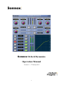
Sonnox Oxford Dynamics
Operation Manual
Version 1.1 9th January 2012
1
1.
Introduction
The Oxford Dynamics plug-in is a direct emulation of the extremely flexible and capable unit
used in the OXF-R3 professional mixing console. Resulting from many years research into
professional dynamics applications, it offers separate Compressor, Limiter, Expander, Gate
and sidechain EQ functions, with fully independent control of all parameters. Features such
as selectable time constant curves and variable soft compressor functions allow the user to
confidently tackle all common uses of compression, from subtle unobtrusive level control and
mastering functions to the creation of great artistic effects.
The use of a feed-forward architecture with logarithmic sidechain processing, and the use of
look-ahead techniques, ensures exemplary sonic characteristics and dynamic accuracy, with
an artistic capability simply unavailable from any other single unit, analogue or digital. This
highly sophisticated and professional product has the power and flexibility to obviate the
need for many of the separate applications that most users keep for specific tasks.
The Oxford Dynamics features include:
•
Separately controlled sections for Compressor, Limiter, Gate and Expander, providing
an extremely wide range of dynamic control
•
Fully featured 2-band sidechain EQ with audition function
•
Additional surround format Compressor and Limiter with selectable Sub channel
filtering and sidechain gain contribution control
•
Selectable linear and exponential time constant curves
•
Highly accurate logarithmic sidechain processing
•
Fully variable soft ratio function for extreme programme tolerance and highly musical
compression operation
•
Variable harmonic enhancement for extra loudness, presence and ‘punch’
•
Selectable re-dithering function for word length reduction in mastering situations
•
Extremely low signal path insertion noise and distortion, below -130dBr
•
All functions are fully automatable
•
Automatic mono-stereo detection and adaptation as appropriate
•
Mono-only versions to allow processing of one side of a stereo track
2
Dynamic signal level control has grown in complexity and popularity from humble
beginnings to an essential part of the sound production process. Originally conceived as a
method to automatically correct for performance variation and broadcast transmission
limitations, dynamic control has evolved beyond this to engender complete artistic cultures
and idioms, resulting from the continuous expansion of the artistic effects provided by such
processes. As a result of these trends, many diverse types of compression mechanisms have
been developed over the decades aimed at a very wide range of uses and effects.
By providing an unusually wide range of control, along with multiple timing laws and
operational subtlety, the Oxford Dynamics section can achieve impeccable results in the
widest range of uses, from sensitive almost imperceptible dynamic compression on vocals
and programme material to harmonic enhancement of instruments and dramatic artistic audio
effects.
3
2.
Operation
2.1
‘Front Panel’ Controls
The separate dynamics functions have their own control sets that are available at any time by
operating the appropriate ACCESS button for that section. Operating the IN button for any
section will force the controls for that section to the foreground of the GUI for convenience.
The IN buttons can be used to toggle the contributions from each section on and off, for
comparison purposes. Button illumination displays indicate which sections are in and which
control set is being accessed. Control setting parameters are permanently available during
operation, and specific values can be typed into the parameter windows at any time. Where
functions apply to the overall dynamics rather than single sections, their parameters and
buttons are visible permanently.
Overall input/output levels and section contribution meters are permanently visible for
reference. The four section gain contribution meters (top centre of the display), GATE, EXP,
COMP, LIMIT display the gain reduction contribution of each section separately, the
maximum of which at any time will determine the instantaneous gain reduction of the
complete dynamics plug-in.
4
A live graphic display of the overall level transfer function is permanently displayed (in the
lower right) for reference, and all setting parameter values are visible for any section that is
being accessed.
2.2
Dynamics Control
The Dynamics section comprises of four separate applications, Compressor, Limiter, Gate
and Expander. Although these applications contain several different control types that have
common functions, the operation, ranges and laws of these controls have been optimised
carefully for maximum flexibility within the intended specific use of that section. The very
wide control ranges offered within the applications are accommodated in the user interface by
employing specific control laws that encourage experimentation over a very wide parameter
set, without the loss of finer control sensitivity and detail. Careful consideration has also been
given to the dynamic behaviour of the time constants, as this factor is largely responsible for
the sonic character of any dynamics application.
In order to make best use of this application, it is necessary to acquire a basic understanding
of dynamics processing in general, and the particular architecture of the Oxford Dynamics
plug-in. The following sections address these issues.
2.2.1 Basic Dynamics Architecture
There are two basic types of dynamics architecture in common use; these are often termed as
feed-forward and feedback types. The feedback type uses its own output to compute required
gain reduction:
X
Level Detect
and Sidechain
5
This method had an advantage in early analogue compressors because the complex and
largely unpredictable laws of early gain reduction elements could be somewhat decoupled
from the total level transfer characteristic of the application (because the design made use of
level feedback). With the introduction of better solid state VCAs and accurate logarithmic
sidechain processes, this method has largely been abandoned in favour of the feed forward
model since it has a much greater degree of control parameter separation and intrinsic
accuracy.
The Oxford Dynamics section is a feed forward type processor. By this we mean that the gain
controlling sidechain element of the processor works by evaluating the programme level at
the input, and calculating the required output gain by dead reckoning:
X
Level Detect
and Sidechain
This widely conforms to the architecture of most popular modern analogue dynamics sections
employing voltage-controlled amplifiers. In a digital design the feed-forward model has
additional advantages, which include the possibility of extremely well controlled and variable
time constant laws and sonically accurate gain control elements. Also look-ahead processing
(using delay) allows gain control to be initiated in advance of the signal, without losing signal
quality.
6
2.3
Compressor
There are two main factors that describe the function of a compressor: a level versus gain
function, which is generally assumed to be independent of the time constants, and a dynamic
gain function which exhibits more complex dynamic behaviour over time. To explain the
operation of the compressor section, it is useful to split these two categories. The following
section refers to the level versus gain behaviour of the compressor application in the Oxford
Dynamics plug-in.
The Oxford plug-in employs logarithmic sidechain processing, which means that all signal
parameter setting (and time constant action) occurs in the ‘decibel’ domain. This makes it
possible for all control functions to remain independent and therefore provides the greatest
level of control for the user. To get the best results from the compressor, it will be useful to
gain an understanding of the specific effects of its control parameters by reading the
following pages carefully.
7
2.3.1 Compressor Threshold Control
The threshold control sets the level (referred to dBFS) at which compression and gain
reduction will begin. The control has a linear decibel law over the range. The following graph
illustrates the threshold control operated in 5dB increments with the ratio at max (1000:1) to
–20dBr.
2.3.2 Compressor Ratio Control
The ratio control sets the rate at which gain reduction will occur when the input level goes
beyond the set threshold level. The control has a 1/Ratio law so that gentle compression can
be achieved despite the wide range of the control. So, from 1:1 to 2:1 ratio occurs over the
first 50% of the control range and 4:1 ratio occurs at 75% control rotation etc. Full limiting is
achieved with the control at 100%.
8
2.3.3 Compressor Soft Ratio Control
The soft ratio function provides a gentle, minimum rate transition between the region below
the threshold and the compressed region of the curve. A further threshold, below the main
threshold control setting, defines the start of the soft curve. The program signal is therefore
compressed progressively harder as it gets louder within this region, until the full
compression defined by the ratio control is achieved. Adjustment is made via the SOFT
button, which provides fixed settings from 0dBr to –20dBr in 5dB increments.
2.3.4 Compressor Make-Up Control
The MAKE-UP control allows manual compensation for level loss during compression up to
a maximum of +24dBr. This control operates independently from all other settings and can be
considered as an output level control. The gain makeup is applied to all Dynamics functions
but operates only when the compressor is IN.
9
2.3.5
Using Level Control Functions
Since all level control functions in the Oxford Dynamics Compressor operate entirely
separately, a very high degree of control for a wide range of common use is possible, in
particular the plug-in does not impose any particular style constraint on the user. This section
explains some of the commonly used techniques, and how they may be achieved using the
Dynamics plug-in.
In the most general terms, the extremes of compression usage fall into two main categories,
dynamic level control and audio effect generation. For simple level control, such as
controlling performance variation in vocals, instruments and final programme material, we
most often require the most transparent compression with minimum artefacts caused by the
dynamics’ control. However, to generate audio effects and distortion the reverse is true and
we need to make the audio character of the compression a dominant part of the final result.
In order to understand how we achieve these two different styles of result, we must remember
that, in general, we are much more sensitive to the rate of change of level than we are to
relative gain. So in order to generate prominent audio effects using the compressor, we need
to generate a significant rate of change of gain action by using both hard compression gain
curves and the creative use of time constants. However, for general unobtrusive level control
we should be avoiding all of this, and opting for the gentlest compression gain curves and
least obtrusive time constant settings that integrate well with the programme style.
2.3.6
General Programme Compression
There are two main basic philosophies that underlie approaches to unobtrusive compression.
The aim of the following pages is to explain these concepts, make comparisons between
them, and show how enhanced results can be achieved using the Oxford Dynamics
Compressor.
10
2.3.6.1 ‘Least Possible’ Approach
The first and most obvious, which we will call the ‘least possible’ approach, is to leave the
majority of the programme uncompressed, forcing the compression to deal only with the
louder passages. This method has a definite psychological advantage in that one gets the
feeling that the majority of the programme remains unaffected. There is also some possible
technical merit (especially for legacy designs) in that the compressor is working ‘less often’
and over a restricted range, thereby avoiding some of the potential errors in the application.
The above graph illustrates this kind of approach. The situation here is that the programme
goes ‘over’ on the loud passages, so we seek to control the loud portion only by setting the
threshold relatively high (-5dBr) and setting the ratio high enough (ie. between 3:1 and 4:1)
to prevent the ‘over’. With the Oxford compressor, the threshold and gain make-up controls
can be used to accommodate this approach over a 24dB range of relative input levels, without
change in the sonic character of the programme.
This method has the major disadvantage of risking increased rate of change disturbance
because the transition between non-compressed and compressed programme regions is sharp.
There is therefore a considerable reliance on longer time constant settings in order to reduce
the sonic effects of the compression. In other words, we need to seek to control the rate of
change using time slewing rather than level progression. Whilst this approach would naturally
form a good basis for using the compressor as an audio effect, it is less suitable for composite
programme control.
11
One way to alleviate the compression transition effect is to smooth it out using the soft ratio
function:
The above graph shows the action of the SOFT ratio control set to 5dB applied to the
previous settings. Starting the compression earlier, and increasing the compression ratio up to
the max level point, smoothes out the transition point at the onset of compression.
The main advantage of this method (often referred to as ‘over easy’) is that faster time
constants can be used before the compression artefacts become too obtrusive. This means that
the programme can be made to sound louder and more present without increasing peak levels,
despite the fact that more of it is being compressed. Also, the use of faster time constants
further reduces peak overshoot, so there is less need to employ limiting in the signal chain.
It should be noted that with the Oxford plug-in, the application of the soft function will
always result in the same maximum output level. This means that you can apply the soft ratio
function at will, with only a minimal need to adjust the threshold and ratio controls.
12
2.3.6.2 ‘Overall Compression’ Approach
This concept advocates that a more transparent sounding compression can be achieved if a
relatively large portion of the programme level range is under continuous compression. The
rationale here is that the rate of change disturbances are minimised because the compressor
spends less time going over the onset of compression transition range. But the downside is
that peak loudness is less well controlled, therefore quite heavy additional peak limiting is
sometimes required to tailor the performance into an overall mix.
The above graph illustrates this general approach. The threshold is set to around –30dBr and
the ratio is set to 2:1; the level loss has been compensated manually by the make-up control.
In this case we can see that quiet parts of the programme output below –30dBr are boosted by
15dB. The most prominent 30dB range of the programme is represented by only a 15dB
dynamic range, whilst still maintaining a good representation of the dynamic information in
the performance.
This approach can significantly improve the loudness of programme material over a wider
range, where maintaining a decent dynamic range in the output is an important feature.
Therefore this approach works well for the compression of classical, choral and solo
instrumental work.
13
2.3.6.3 Combined Approach
From the above discussion we can see that the digital compressor, with its sonically
transparent gain control process and very accurate level control, allows very effective
influence over a wide dynamic range of programme material, without incurring some of the
problems associated with analogue units. The range of control provided by the Oxford
Compressor allows the construction of many possible combinations and variations of the
above approaches, in order to achieve a superior result. The following graphs illustrate
suggested settings to achieve some interesting dynamic results from the plug-in, by using a
combination of the above approaches.
2.3.6.4 Suggested Settings
Maximum Loudness
This graph shows one method to
achieve maximum loudness and
presence for programme where
dynamic range is unwanted (ie.
pop music, spoken commentary
etc.). The intention is to get the
prominent parts of the
programme as loud as possible
without incurring too many
compression artefacts that would
require long time constants to fix. The gain is set to maximum (+24dBr), the ratio is set to
1000:1 (limiting) and soft ratio is selected at 15dB. The threshold is then reduced (to around
–25dBr) until the maximum level is achieved. The idea is to compress the programme
material to ever-greater degrees as it gets louder, until it is fully limited at maximum output.
The selection of the 15dB soft ratio curve is a compromise between unwanted compression
artefacts, available gain and total loudness.
It should be noted that, as the top 10dB of programme has virtually no dynamic information
at all, this sort of approach is likely to gain favour within the current popular music idiom. It
can also be very useful in situations where fast and smooth action is required on a vocal, with
minimal distortion.
14
Minimum Obtrusion
This graph shows a minimum
intrusion type curve using a
ratio of around 2:1 and a soft
ratio setting of 10dB. This
style of compression will bring
up the softer passages by
around 12dB and
progressively compress the
loud passages into half the
original dynamic range — in a
very subtle and unobtrusive fashion. Settings of this kind can tolerate fast time constant
settings without obvious sonic artefacts, and are therefore very effective in classical music
programme or other situations where a good degree of dynamic realism needs to be
preserved.
15
2.3.7 Timing Functions
The relationship between gain compression and temporal behaviour is absolutely crucial to
successful dynamic control, whether the user is aiming for the unobtrusive control of levels
or a completely stylised sound effect. Much of the artistic character in the massive range of
renowned compressors is determined by subtleties in the timing behaviour of these units
under complex musical signal conditions.
In order to encompass as much of this valuable artistic legacy as possible, the Oxford
compressor plug-in incorporates a very wide range of timing control, using both linear dB
and exponential dB time dependency curves. In this way the plug-in can be used to create the
widest range of artistic effect without imposing an overwhelming and unavoidable character
of its own. The plug-in should therefore be considered as a powerful and flexible tool rather
than a specific ‘style’ of compressor. The following paragraphs describe the operation of the
compressor’s timing controls and its time dependency behaviour.
To generate the timing illustration graphs, the following stimulus was used as the reference.
This is a tone burst signal that consists of 0.2 sec of full level signal preceded and followed
by 0.8 sec of signal at –20dBr.
16
2.3.7.1 Compressor Attack Control
The attack control varies the timing behaviour of the compressor at the onset of gain
reduction, either due to the arrival of a peak level above the threshold or the further increase
in a level already above the threshold.
"
The three diagrams above show the action of the attack control from minimum through mid
range to maximum setting.
17
2.3.7.2 Compressor Release Control
The release control varies the timing behaviour of the compressor during the recovery period
after a gain reduction, when the signal level has reduced from previous levels above the
threshold.
The above diagrams show that action of the release control from minimum to half range
(maximum range is too long to show successfully on this diagram).
18
2.3.7.3 Compressor Hold Control
The hold control varies the amount of time between a reduction of levels above the threshold
and the onset of the release time. It provides a period after gain reduction where a slower rate
of recovery occurs.
The above three diagrams show the action of the hold control from nearly minimum to 75%
of maximum, with an intermediate position with the release set to minimum. When the
compressor is in recovery after a loud passage, the full value of the release setting time is
reached only gradually over the period of the hold time. This produces an extended period
when the release time is maintained at slower rates in order to allow faster gain recovery
without excessive distortion at low signal frequencies. Since the release time is effectively
multiplied by the hold time, very long total gain recovery times can also be obtained by using
the release control in conjunction with the hold control.
19
2.3.8 Compressor Timing Laws
The Oxford compressor offers three compression types designated NORMAL, CLASSIC
and LINEAR, selected sequentially via a button in the centre of the Dynamics display. The
time constant laws employed define the major difference between these types.
The Oxford Dynamics uses both Exponential dB/time and Linear dB/time laws as illustrated
below:
Exponential/dB curve used in Normal and Classic types
Linear/dB curve
The Oxford Dynamics time settings are displayed as real time constants when in exponential
mode. In linear mode the display is scaled to correspond to the time required for a 10dB
change of level. This provides a degree of parity between the perceived timings of the two
laws, which facilitates comparison and selection between compression types. These two laws
have very different sonic characteristics.
20
2.3.8.1 Exponential/dB timing (Normal and Classic types)
The Exponential/dB curve is by far the most popular law used in a great many well-respected
compressors, and is the natural result of more recent analogue units employing logarithmic
sidechains and resistor/capacitor time constants. The Exponential/dB law has some
interesting characteristics. First, the time taken to complete a compression event tends to stay
the same however large the dynamic signal excursion is. Also since the peak rate of change
of gain increases with dynamic excursion, the resulting harmonic content due to compression
tends to follow the loudness of the programme in a way the ear expects. This helps to mask
the effects of the compression, and thus provides the most forgiving solution, being tolerant
to differing timing settings and programme material. This makes it the best choice for general
compression use and overall dynamic control of complex musical programme material.
The diagrams above illustrate the action of the exponential law. The first shows 10dB gain
reduction (scaled for comparison) and the second one shows 30dB. As can be seen, the initial
rate of change is much increased in the attack period and the total time for attack is similar
despite the increased level transition.
The CLASSIC type selection is a subset of the NORMAL type, with timing controls fixed to
nominal values to match a range of popular legacy units. All other controls behave as the
NORMAL type. This type selection is quick to set up and is most useful as a general-purpose
channel compressor.
21
2.3.8.2 Linear/dB timing (Linear type)
The Linear /dB law, in some respects, exhibits the reverse behaviour of the Exponential law.
Because the rate of change of gain is constant (as set by the timing controls), the greater the
signal dynamic excursion the longer the compressor will take to complete a gain change.
Also, since the total time that the compressor spends in attack or decay is proportional to the
size of the gain excursion, the harmonic content of the compression artefacts will seem to
reduce in frequency content the louder the signal excursion is. This type of compressor is
useful for generating dynamic audio effects because the sonic character of the compression is
much more affected by time control settings and programme material than the exponential
type.
The diagrams above illustrate the action of the linear law. The first shows 10dB gain
reduction (scaled for comparison) and the second one shows 30dB. The rate of change is the
same during the attack period, and therefore the total time for attack (and subsequent release)
is increased with greater level transition.
Please note that the Linear timing law is generally unsuitable for the control of
programme dynamics and modulation levels because of its unnatural sounding
relationship between level excursions and perceived overtone generation.
22
2.3.9 Using Compression Timing Functions
The setting of timing functions can drastically affect the sonic character of compression, and
there are many different approaches to compression timing, often in pursuit of ever-changing
fashion! There is, therefore, no right or wrong approach to this task. However, to successfully
build up your own portfolio of artistic sounds using a variable parameter compressor such as
the Oxford plug-in, a basic grounding in the sonic effects produced by timing will be useful.
The following section sets out to describe the basics of timing settings and the range of sonic
effects available from the Oxford plug-in. By changing time constants, many effects can be
generated such as:
•
Attack times can accentuate and bring percussion instruments to the foreground if
slow, and push them into the background if fast.
•
Attack times can re-model the sound of a percussion instrument by creating gain
overshoots if relatively slow, ie. make a soft event produce a harder sound, or a fast
attack can soften a hard sound by attenuating its peaks.
•
Fast attack with fast release can generate pleasing harmonic distortion and ‘warmth’
that is focussed on the lower frequencies of a signal, by modulating the gain during
the period of the musical waveform.
•
Fast release times can significantly increase the relative loudness of programme by
filling in the programme with accentuated ‘quiet passages’. A slow release will do the
opposite.
•
Moderate to fast release times can lengthen apparent reverb time.
•
Moderate release times can accentuate the musical timing of piece if set to recover
during the natural rhythm of the music.
•
There are many approaches to programme level control, which are largely decided by
whether one is trying to get maximum loudness and excitement, enhancing
reproducibility at low reproduction levels or just trying to control overloads. In
mastering situations, either or all of these may be appropriate, along with many other
subtleties such as matching impressions between tracks destined for an album release.
23
The following provides a general description of some effective approaches and starting
points:
2.3.9.1 Fast as Possible Approach
To obtain absolute maximum modulation and minimum dynamic range, the best approach is
to set release times to minimum, increase the hold time just enough to the reduce LF
distortion to acceptable levels, and increase the attack time just enough to allow some
overshoot on percussive peaks, in order to retain some impression of programme dynamics.
The appropriate level of compression can then be obtained using the threshold, ratio and soft
ratio controls. The overshoots produced by the attack times can be controlled by the use of
the programme limiter section.
2.3.9.2 Natural Dynamics Approach
To obtain a more natural compression a good starting point is to set the attack and release
controls to mid positions with hold control at minimum (this is the fixed setting of the Classic
compressor style). This approach aims to match to some degree the dynamics of the ear’s
response and recovery from loud sounds at relatively high sound pressure levels. Variations
on these moderate settings can yield realistic results if appropriately adjusted to suit the
intended reproduction levels of the programme.
2.3.9.3 Slow and Gentle Approach
For level control with the least possible intrusion, set the attack and release times to the
longest possible times, perhaps with the addition of the hold control to increase the release
times further. This ensures that the highest levels within the programme material are
controlled gently, and the gain recovery in the quiet passages is almost imperceptibly slow.
This method is most effective when used in conjunction with the larger soft ratio settings, as
this ensures that compression commences well before the target maximum level, providing a
degree of prediction.
24
2.3.9.4 Artistic Effects
The manipulation of timing within compression can create some very useful effects. In
particular, gain overshoots produced by slow to moderate attack times can be very useful at
tightening up soft percussion sounds. However, a note of caution is needed for users of
workstation applications in that effects such as these may cause unexpected programme
clipping that may prevent the available range of possible sounds being fully appreciated. In
particular, for systems that lack overload margin between plug-ins or within their mixing
structures, the extra short term peaks produced by creative compression may be prematurely
clipped within the host application because essentially there is no range (headroom) to
accommodate them. In this case a reduction of input levels and/or a suitable reduction of the
threshold and gain make-up values may be needed to fully realise the new sound within the
intended mix.
25
2.4
Limiter
From a level profile perspective, a limiter is essentially the same as a compressor with its
ration set to infinity. However, the use of much faster attack times with a somewhat different
dynamic behaviour allows faster and more effective reduction of peak levels. Historically,
limiters were developed mainly for radio transmission systems where absolute limits on
modulation were needed.
In this situation, simple saturation was not useful, since the HF energy produced by signal
clipping could still breach modulation limits. The earliest limiter designs were mostly fast
attack slow release types, designed to minimise audibility problems. Since then many
different designs and much more complex methods have been developed. And more recently,
using limiting and its side effects has almost become an artistic exercise in itself, being partly
responsible for the recent trends for absolute maximum modulation and loudness, currently
favoured amongst producers and broadcasters of popular music. As a result of this expanding
trend for stylised dynamic control, the demarcation between limiting, compression and even
EQ has become increasingly blurred, as an increasing number of ever more complex devices
become available that make use of all of these functions in a quest to produce impressive
results.
The Oxford plug-in limiter, however, is presented as an entirely separate and direct process
that is designed and optimised specifically for highly efficient and musical peak limiting
functionality. Despite being simple and intuitive to understand and operate, superior results
can be obtained from highly accurate level and timing behaviour, making optimal use of
look-ahead processing that acts on signal peaks prior to their arrival at the gain control
element. Although the limiter is designed to complement the compressor section of the plugin, it can be equally well used as a stand alone application for enhanced peak level control
and programme modulation maximisation.
26
2.4.1
General Description
The limiter’s controls are presented similarly to the compressor’s except that there is no ratio
control. The time constant functions, although similar to the compressor, have different
ranges. In particular the attack time can be adjusted to be much faster than the compressor. It
should also be noted that the threshold levels are related to the output level of the whole
dynamics application (rather than the input level), so that any increase in gain produced by
the compressor and gain make-up do not affect the calibration of the limiting target levels.
27
2.4.2 General Limiter Operation
There are many methods and approaches to programme limiting that are favoured amongst
users. In general however, these fall into the two main categories described below.
The least intrusive kind of limiting is achieved with a fast attack and a relatively slow release,
adjusted to suit the general timing of the music. Very long decays, often favoured in classical
music productions, can be achieved with the Oxford limiter by using a combination of both
release and hold times. Due to the look-ahead processing, the Oxford limiter also has a
significant range of attack time that can be used without peak level overshoot. This means
that a slower and gentler limiting can be achieved during the onset of loud passages within
the programme material, without breaching maximum level, as set by the threshold control.
2.4.3 Maximising Loudness with the Limiter
A recent popular use of programme limiting aims to maximise the relative loudness and
average modulation of music by reducing the short-term peak levels within the programme
waveform. This makes it possible to increase the overall volume (gain) of a piece without
getting obvious overloads (red lights) on the final mastered work. The success of this method
depends on the amount of peak reduction that can be obtained without objectionable loss of
quality to the programme. Maintaining the quality of the peaks, without reproducing their
maximum levels, relies on a degree of ‘peak remodelling’.
The basic approach to this function is to initially set attack, hold and release controls to
minimum, for fastest possible action. Then reduce the threshold control to progressively
reduce the gain of the programme, only during the very short periods where peaks occur. The
sound of the peaks can then be adjusted by increasing the attack period to soften the edges
such that a degree of realism is retained, despite the reduction of instantaneous levels during
that period. Since the Oxford limiter has a fairly large look-ahead period, it is possible to
increase the attack time significantly without allowing the peak levels to pass. It is therefore
possible to re-model the limited peaks considerably in real time, retaining good programme
realism despite large degrees of peak reduction. If it is necessary to increase recovery times
after peaks, for instance due to LF modulation content, it is better to use the hold control for
this purpose, as the recovery time is faster for a given overall period than by increasing the
release time. The programme level can then be increased so that the new peaks just reach
maximum level again. Depending on the material, average programme modulation may be
increased by 6dBr or more by using this method.
28
2.5
Expander
The dynamics’ Expander section control functions are presented similarly to the Compressor
and Limiter sections, except that a RANGE control is added. The architecture of the
expander conforms to what is often described as ‘downward expansion’, which means that
the application only works to attenuate existing signals below a set threshold, and cannot
produce any additional gain for signals above the set threshold level. In practice, this means
that, although the purpose of the expander is to increase dynamic range, it can only achieve
this by reducing the signal level in the first place.
The THRESHOLD control sets the level below which the expander will become active.
The RATIO control sets the gain slope rate that signals below the threshold will be
attenuated with respect to the input levels.
The RANGE control sets the lowest limit that any attenuation caused by expansion can reach.
29
Expanders may be used for many purposes, both technically and artistically. These include
background noise reduction and file clean up, the reduction of ambient noise disturbance in
live recordings, presence and dynamic profiling of instruments, and creative control of
ambient reverb etc. Because the Oxford Expander has 20 samples of signal preview, it is
particularly useful for instrument dynamic profiling, as it can act on the signal before gain
control actually occurs, meaning that, for example, you can actually profile the leading edge
of a percussive attack.
2.6
Gate
The Gate controls of the plug-in are presented similarly to the Expander function, except that
there is no Ratio control. Programme gating has become ever more popular in recent years,
since its inclusion in some professional console systems. Originally intended as a technical
tool for tape noise suppression and similar functions, many useful and often fashion changing
artistic effects have been achieved using gates.
30
The Oxford plug-in Gate has many advanced design subtleties that are based on long
experience in the artistic use of gating.
The basic architecture of a gate is similar to an expander with infinite ratio, and therefore acts
much like a programme switch. Signals below the set threshold are cut and only those above
this are passed to the output. The gate also has level hysteresis, such that once opened by
signal above the threshold, a subsequent signal level reduction of 4dBr is required to close the
gate again.
The residual signal level for programme below the threshold is set using the RANGE control,
as in the expander section.
Since the gate effectively operates on signals before gain control is affected, the ATTACK
control can provide a significant range of attack profiling without missing the peaks within
the programme material. This provides the capability to change the sonic character of the
attack period of the gate
The HOLD function provides time hysteresis by effectively providing a delay after the gate
opening, and before subsequent closure can occur, which is very useful for trimming gate
activity to match programme event timing durations and nested rhythms within the music.
The RELEASE control provides the ability to tailor the recovery period to match the
programme material, and provide artistic effects.
31
2.7
Sidechain EQ
A high specification two-band Sidechain EQ (S-C EQ) is provided to allow de-essing and
other modifications of sidechain frequency response. The EQ processing section may be
routed to either the dynamics sidechain or the main signal path or both simultaneously, by
selection of the independent EQ-SC and EQ SIGNAL buttons.
2.7.1 Sidechain EQ Controls
All Gain, Frequency and Q controls operate separately, and their values are displayed
permanently. Values may also be entered directly by clicking on any desired display field.
LF GAIN — Controls LF section gains between -20dB and +20dB.
LF FREQ — Controls LF peak frequency between 20Hz and 1KHz.
LF Q — Controls LF Q from 0.5 to 16.
32
HF Q — Controls HF Q from 0.5 to 16.
HF FREQ — Controls the HF section frequency from 500Hz to 20KHz.
HF GAIN — Controls LF gains between -20dB and +20dB.
LF SHELF and HF SHELF — Individually select shelving responses for LF and HF
sections.
INPUT GAIN* — Adjusts the input level to the EQ section from –20dB to 0dB to avoid EQ
clipping when in boost settings.
EQ S-C — Routes the EQ processing into the sidechain.
EQ SIGNAL — Routes the EQ processing into the main signal path.
(SC-EQ) IN — Toggles the sidechain EQ in and out for comparison purposes.
* Note that the EQ gain control is needed to avoid signal clipping when the EQ is used in
the signal path with boost settings. Therefore changes to the EQ gain will modify effective
thresholds in the dynamics section. However, due to internal overload margins within the
dynamics, it is legitimately possible to boost EQ signal levels up to +24dBr when used in
the sidechain, even though these signals would cause overloads if the EQ were routed to
the main signal path.
33
2.8
Warmth
The WARMTH process confers additional loudness, punch and definition to the sound of the
dynamics section. The operation of this process is to impose a harmonic profile onto the
signal that increases the density of higher value samples within the programme, in order to
boost average modulation levels without an increase in peak levels or the risk of digital
clipping. The Warmth function is engineered to achieve this without the loss of dynamic
information within the programme material.
Another very important purpose of the Warmth function is to accommodate internally
generated levels up to 6dB greater than notional digital maximum, without causing increased
peak levels or hard clipping. The main advantage is that short term level peaks and
overshoots, resulting naturally from the artistic use of compression, can still provide
harmonic information to the programme even though they may represent levels above
maximum digital modulation, that would be subjected to hard clipping if left untreated.
34
The process also adds subtle warmth to the programme material that is reminiscent of valve
systems, and is similarly tolerant of overloaded or previously clipped signals, avoiding much
of the harshness associated with these conditions. Significant artistic effects may therefore be
achieved by deliberately overdriving the Warmth processing by increasing the compressor
gain make-up beyond normal levels and allowing the Warmth processing to control the peak
signal levels.
When selected, the Warmth function operates on the complete signal chain of the dynamics
plug-in, and is therefore applied to the signal even if no compression functions are operative.
The AMOUNT control varies the contribution of the effect from 0% (no effect) to 100%
(max effect). Full advantage of the clip removal will occur only at maximum effect
contribution, but harmonic enhancement may be achieved at all settings above zero.
2.9
Max Trim Control
The MAX TRIM control (only available when the WARMTH function is selected) allows
very fine gain trimming on the final output of the Dynamics processing. The purpose of this
function is to allow very precise alignment of maximum modulation levels, and the
accommodation of the differing meter characteristics, often found in ancillary equipment
used in production and mastering processes. A fine balance between digital maximum
modulation and target meter overload indication can be achieved easily using this control.
2.10 Dither Control
A button (available with all section selections apart from S-C EQ) provides selectable redithering function for word length reduction in mastering situations. The button toggles
between NO DITHER, 16 Bit Dither and 24 Bit Dither.
35
2.11 Buss Compressor (Pro Tools TDM only)
2.11.1 General Description
The Buss Compressor is a separate instantiation that allows full multi-format compression
and limiting with Sub channel generation and control (up to 5.1). The Compressor, Limiter
and Warmth processes are identical to the channel dynamics plug-in (as described in the
preceding sections of this manual), but the Expander and Gate functions are removed to
release processing load for extended multi-format application. A 24dB/octave variable low
pass filter replaces the Sidechain EQ, to allow Sub channel generation from normal wide
band buss contributions, if required.
36
2.11.2
Description of Controls
The ‘front panel’ controls generally operate similarly to the channel compressor. The
functions are listed below.
1. IN Buttons — Toggle section contributions in and out for comparison purposes. Selecting
IN for a main function will also force ACCESS to that section’s controls.
2. ACCESS Buttons — Accesses controls for that section.
3. INPUT and OUTPUT Metering — Provide a permanent display of input and output
levels for each contribution to the surround buss.
4. Gain Transfer Display — Displays current overall gain transfer curve.
5. Time Constant and Type Selector — Selects the compressor time constant dependency
laws, NORMAL, LINEAR and CLASSIC. The CLASSIC setting is a subset of the
exponential type with fixed time settings corresponding to a DBX 160 type compressor.
37
6. External Key Input Selector (Pro Tools only) — Selects externally derived signal to the
sidechain input.
7. Soft Ratio Selector — Selects soft ratio starting threshold in 5dB steps to –20dB below
threshold control setting.
8. RATIO — Controls the ratio of the compressor and expander processes. It is inoperative
in limiter and gate functions.
9. THRESHOLD — Controls the threshold of compressor or limiter function as selected.
10. ATTACK — Controls the attack time of compressor or limiter function as selected
11. HOLD— Controls the hold time of compressor or limiter function as selected
12. RELEASE — Controls the release time of compressor or limiter function as selected
13. MAKE-UP — Applies gain make-up to a maximum of +24dBr only when the
compressor is operative.
14. Gain Reduction Meters — Separate metering displays for relative gain reduction
contributions of both compressor (COMP) and limiter (LIMIT). Note that the overall gain
reduction at any time is the larger of these contributions.
15. SONNOX Button — Provides access to option menu items:
Allows selection of circular or conventional mouse control. Additionally, overload light
recovery times of 2 or 5 seconds may be selected to allow easier operation and overload
monitoring within the dynamics function.
38
2.11.3 Buss Compressor Architecture
The Buss Compressor employs common sidechain processing to all buss contributions
simultaneously. This avoids unwanted modification to panning and balance during
compression gain changes, but it does mean that parameter settings will apply to all main
busses and increased level on any buss will result in increased compression on all outputs.
The Sub channel is treated differently, in that the contribution the Sub channel makes to the
overall compression and the effect that overall compression has on the Sub channel are both
under user control. This means that you can have the Sub channel contributing to the
common sidechain but its own signal is not compressed. Or you can arrange the Sub channel
signal to be compressed but exclude this signal from the common sidechain to avoid
‘pumping’ during loud LF passages. Or you can exclude the Sub channel from both the
sidechain and compression so that it operates independently. The controls allow any
proportional combination of these conditions to be set up as illustrated below.
The SUB TRIM control sets the amount that the Sub signal contributes to the compressor
sidechain. And the SUB PASS control sets the amount that the overall compressor sidechain
will affect the Sub channel output signal.
39
2.11.4 Description of Sub Channel Controls
1. ACCESS Button — Accesses controls for the Sub channel processing.
2. IN Button — Toggles Sub filter in and out of the signal path.
3. LP FILTER — Sets the Sub channel filter cut off frequency between 50Hz and 150Hz (at
24dB/octave).
4. SUB PASS — Sets the proportion of the compressor contribution to the Sub channel gain,
from 0 – 100%.
5. SUB TRIM — Sets the proportion that the Sub channel signal contributes to the
compressor sidechain, from 0 – 100%.
40
Note that with SUB PASS and SUB TRIM controls both set to 100%, the sub channel will
be completely included in the compression function, and be treated just like the main
channels. With both controls set at 0%, the Sub channel will be completely independent and
will not be included in, or affected by, the Dynamics functions.
41
3.
Description of Controls
This section provides a summary of the ‘front panel’ controls you will encounter when using
the various sections of the Dynamics plug-in (the illustration below is of the Compressor
controls):
IN Buttons — toggle section contributions in and out for comparison purposes. Selecting IN
will also force ACCESS to that section’s controls.
ACCESS Buttons — accesses controls for that section.
INPUT and OUTPUT metering — provides a permanent display of overall input and
output levels.
Gain Transfer Display — provides a graphic display of the current overall gain transfer
curve.
Time Constant and Type Selector — this button toggles the compressor time constant
dependency laws between NORMAL, LINEAR and CLASSIC. The CLASSIC setting is a
subset of the exponential type with fixed time settings corresponding to a DBX 160 type
compressor.
42
SOFT RATIO Selector — selects the soft ratio starting threshold in 5dB steps to –20dB
below threshold control setting.
RATIO — controls the ratio of the compressor and expander processes. It is inoperative in
limiter and gate functions.
THRESHOLD — controls the threshold of any dynamics function selected.
ATTACK — controls the attack time of any dynamics function selected.
HOLD — controls the hold time of any dynamics function selected.
RELEASE — controls the release time of any dynamics function selected.
MAKE-UP — applies gain make-up to a maximum of +24dBr only when the compressor is
operative. In the Gate and Expander functions the control is used for RANGE adjustment.
Gain Reduction Meters — separate metering displays (GATE, EXP, COMP, LIMIT) for
the relative gain reduction contributions of each section. The overall gain reduction at any
time is the larger of these contributions.
Options Menu — clicking the Sonnox button
produces a drop-down options menu (see right).
Clip Lights – determines the approximate time
that the overload indicator will stay on for when
the plug-in has detected a full-level sample at
either its input or output.
Enable Sonnox Toolbar – displays or hides the
Sonnox Preset Manager Toolbar.
Show Preset Name Path – shows the hierarchical directory path for Presets that are
stored in sub-folders of the default Preset folder.
43
Knob Modes – Four options determine how the rotary controls (knobs) behave:
With Circular Knob Mode the control is set to the value at which it is first clicked,
and the value then increases or decreases with circular mouse movement.
In Relative Circular Knob Mode a control’s value increases or decreases with circular
mouse movement relative to its initial value.
Linear Knob Mode increases or decreases a control’s value with up and down mouse
movements respectively. Fine adjustments to any control setting can be achieved by
pressing the ‘Apple command’ (Macintosh version) or ‘Shift’ (PC version) key before
clicking on the control to be adjusted and holding this key down during the operation.
This rescales the control rate with the mouse movement, so that very fine adjustments
can be made.
In some host applications the user is given the option to use one of several mouse
modes. Follow Host Mode enables the plug-in to follow the mode selected in the
application.
About Sonnox Oxford Dynamics… — displays the date, version and build number of the
plug-in.
44
4.
Preset Manager Toolbar
The Oxford Dynamics plug-in comes
equipped with its own onboard Preset
Manager, which is displayed as a toolbar at
the top of the plug-in window, just as if the
host created it (see above). The reasoning
behind this is to allow increased portability
of your presets across all the host
applications, while also providing a
consistent and versatile interface. Although
most host platforms allow the creation and
loading of presets, those host-created
preset files are not portable between
different host applications. With the
Oxford plug-ins’ preset manager, you can create a named preset in one host application and
load it when using an alternative application.
The Sonnox Preset Manager is fully described in a companion document — ‘Sonnox
Toolbar and Preset Manager Operation Manual’ — available for download on the Support
Documentation page of the Sonnox website: www.sonnox.com
45
5.
Specifications
Section
Threshold
Ratio/Range
Gate
Expander
Compressor
Limiter
-80 – 0dB
-60 – 0dB
-60 – 0dB
-60 – 0dB
0 - -80dB
0 - -80dB
1:1 - Limit
Gain Make-up
Attack
Hold
5uS* - 26mS
0.26 – 104mS
519uS – 52mS
100uS – 500mS
10mS – 10S
10mS – 20S
10mS – 30S
50mS – 30S
Soft Curve
Release
7.8 – 519mS
5.2 – 519mS
52mS – 3.1S
100mS – 10S
Time constant types
(Start threshold)
Compressor
0 – 20dB
-5, -10, -15 and -20dB
Linear and Exponential
All values in the table are referenced to full scale and time constants apply to a 10dB gain change. Thus
the time value marked * denotes a calculated value for 10dB gain change, since the true figure is 40dB
gain change in 20.8uS (1 sample at 48KHz).
Sidechain EQ
LF
HF
Q
Gain
20Hz – 1kHz
500Hz – 20kHz
0.5 – 16, or shelving
+/-20dB
46
6.
Copyright and Acknowledgements
Trademarks and content copyright © 2007-Present Sonnox Ltd. All rights reserved.
This Product is manufactured and supplied by Sonnox Ltd. under licence from Sony UK Ltd.
The following patents protect this Product: GB2330747, GB2310983, GB2310984,
GB2310985, GB 2342023, US5923767, US5923768
DIGIDESIGN, AVID, and PRO TOOLS are trademarks or registered trademarks of
Digidesign and / or Avid Technology, Inc.
VST is a Trademark of Steinberg AG.
All other product and company names are Trademarks or Registered Trademarks of their
respective holders.
7.
Manual Revision History
Version 1.0 date 1st April 2007 — Generic Sonnox version
Version 1.1 date 9th January 2012 — Updated to reflect current software version
47
Platform Specific Supplement
S1. Supported Platforms
Avid Pro Tools (LE, RTAS, M-Powered, Pro Tools HD) and Pro Tools 10 (HDX & Native)
VST Native
Audio Units Native
S2. System Requirements
These requirements are current at this revision of manual. For latest system requirements,
please see the website www.sonnox.com
Pro Tools
Pro Tools 7, 8, 9 & 10
Approved Pro Tools CPU, OS and hardware configuration (see www.avid.com)
Mac OSX 10.4 or higher
Windows XP / Vista 32 & 64 bit / Windows 7 32 & 64 bit
Ram 1GB minimum
iLok USB key with latest drivers
Audio Units
Audio Units compliant host application (e.g. Logic, Digital Performer etc.)
Mac OSX 10.4 or higher
Ram 1GB minimum
iLok USB key with latest drivers
2nd generation iLok required for 64-bit plug-ins
VST
VST compliant host application (e.g. Nuendo, Cubase, WaveLab etc.)
Mac OSX 10.4 or higher
Windows XP / Vista 32 & 64 bit / Windows 7 32 & 64 bit
Ram 1GB minimum
iLok USB key with latest drivers
2nd generation iLok required for 64-bit plug-ins
48