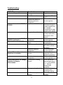
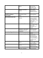
1
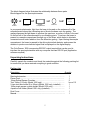
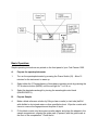
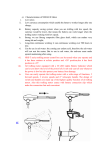
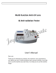
Cole-Parmer
1200 SERIES
SPECTROPHOTOMETER
USER’S MANUAL
Cole Parmer Instruments Company
625 East Bunker Court
Vernon Hills, IL 60061
800-323-4340
TABLE OF CONTENTS
Page number
Safety, General Information ....................................................……….. 3
Introduction
.....................................................…………………….. 4
Working Principle.............................................................……………... 5
Unpacking Instructions .....................................................……………. 5
Specifications
...................................................................………..… 6
Installation ..............................................................................………. 6
Basic Operation ..........................................................……………..… 7
Concentration Mode, Factor Mode
Modes and function
…………………………………… 8
…………………………………………………… 10
Maintenance
Lamp replacement ………………………………………………
Wavelength Calibration Check ………………….……………….
Absorbance Accuracy Checks…………………………………….
Stray Light Check…………………………………………………..
11
11
13
14
Troubleshooting.........................................................................……… 15
2
Safety
This apparatus has been designed and tested in accordance with EN 61010 Safety
Requirements for Electrical Equipment for Measurement, Control, and Laboratory Use,
and has been supplied in a safe condition.
The safety statements in this manual comply with the requirements of the HEALTH AND
SAFETY AT WORK ACT, 1974.
Read the following before installing and using the instrument and its accessories.
General
The apparatus described in this manual is designed to be used by properly trained
personnel in a suitable equipped laboratory. For the correct and safe use of this
apparatus it is essential that laboratory personnel follow generally accepted safe
procedures in addition to the safety precautions called for in this manual.
The covers on this instrument may be removed for servicing. However, the inside of the
power supply unit is a hazardous area and its cover should not be removed under any
circumstances. There are no serviceable components inside this power supply unit.
Some of the chemicals used in spectrophotometry are corrosive and/or inflammable and
samples may be radioactive, toxic, or potentially infective. Care should be taken to
follow the normal laboratory procedures for handling chemicals and samples.
Electrical
Before switching on the apparatus, make sure it is set to the voltage of the local power
supply (see Installation).
The mains plug shall be inserted in a socket provided with a protective earth contact.
The protective action must not be negated by the use of an extension cord without a
protective conductor.
Warning
Any interruption of the protective conductor inside or outside the apparatus or
disconnection of the protective earth terminal is likely to make the apparatus dangerous.
Intentional interruption is prohibited.
Whenever it is likely that the protection has been impaired, the apparatus shall be made
inoperative and be secured against any unintended operation.
3
The protection is likely to be impaired if, for example, the apparatus
•
•
•
•
Shows visible damage
Fails to perform the intended measurements
Has been subjected to prolonged storage under unfavorable conditions
Has been subjected to severe transport stresses
Performance
To ensure that the instrument is working within its specification, especially when making
measurements of an important nature, carry out performance checks with particular
reference to wavelength and absorbance accuracy. Performance checks are detailed
in this manual.
Radio Interference
For compliance with the EMC standards referred to in the EC Declaration of Conformity,
it is necessary that only shielded cables supplied by Cole Parmer be used when
connecting the instrument to computers and accessories.
Introduction
The Cole Parmer 1200 series are single beam, general purpose instruments designed
to meet the needs of the Conventional Laboratory, The Cole Parmer 1200 is ideal for
various applications, such as: Clinical Chemistry, Biochemistry, Petrochemistry,
Environmental Protection, Food and Beverage Labs, Water and Waste Water Labs and
other fields of quality control.
Featuring a digital display of photometric result, easy operation and wavelength range
of 325nm to 1000nm, these instruments are ideal for measurements in the visible
wavelength region of the electromagnetic spectrum.
Working Principle
The spectrophotometer consists of five parts:
1) Halogen lamp to supply the light;
2) A Monochromator to isolate the wavelength of interest and eliminate the unwanted
second order radiation;
3) A sample compartment to accommodate the sample solution;
4) A detector to receive the transmitted light and convert it to an electrical signal; and
5) A digital display to indicate absorbance or transmittance.
4
The block diagram below illustrates the relationship between these parts.
Block diagram for the Spectrophotometer
100%T
0 A
Light
Source
Monochromator
Sample
Compartment
Detector
Display
In your spectrophotometer, light from the lamp is focused on the entrance slit of the
monochromator where the collimating mirror directs the beam onto the grating. The
grating disperses the light beam to produce the spectrum, a portion of which is focused
on the exit slit of the monochromator by a collimating mirror. From here the beam is
passed to a sample compartment through one of the filters, which helps to eliminate
unwanted second order radiation from the diffraction grating. Upon leaving the sample
compartment, the beam is passed to the silicon photodiode detector and causes the
detector to produce an electrical signal that is displayed on the digital display.
The Cole Parmer 1200 incorporates RS232C output terminal that can be used to
interface the spectrophotometer with any computer that has RS-232 port (Application
software required).
Unpacking Instructions
Carefully unpack the contents and check the materials against the following packing list
to ensure that you have received everything in good condition:
Packing List
Description:
Quantity
Spectrophotometer...........……...................................………………….
Power Cord………………………………………………………………....
10mm Optical Square Cuvettes................................…………………..
Test Tubes (1/2 inch) (Model 1200 only) …………………………….….
V-type test tube holder (8 to 25mm) (Model 1200 only, installed) ……
10mm single square cuvette holder (Model 1200 only) ………………..
4-position cell holder (Model 1201 only) (installed)……………………..
Dust Cover...................................…….......…..........………………….…
Manual................................................……..............…………………….
5
1
1
2
box of 12
1
1
1
1
1
Specifications
Wavelength Range
Spectral Bandpass
Wavelength Accuracy
Wavelength Repeatability
Stray Radiant Energy
Photometric Range
Photometric Accuracy
Power Requirements
Dimensions
Weight
Model 1200
325-1000nm
5nm
Better than 2nm
Better than 1nm
<0.5 @ 340 and 400nm
0 to 125%T
0 to 2.0 Abs
0 to 1999C
± 1.0%T
115/230V ±10%, 60/50 Hz
Switchable
408W X 308D X 185H (mm)
15 lbs(6.8kg)
Model 1201
325-1000nm
5nm
Better than 2nm
Better than 1nm
<0.5 @ 340 and 400nm
0 to 125%T
0 to 2.0 Abs
0 to 1999C
± 1.0%T
115/230V ±10%, 60/50 Hz
Switchable
408W X 308D X 180H (mm)
15 lbs(6.8kg)
Installation:
1. After carefully unpacking the contents, check the materials with the packing list
(page 5) to ensure that you have received everything in good condition.
2. Place the instrument in a suitable location away from direct sunlight. In order to
have the best performance from your instrument, keep it as far as possible from any
strong magnetic or electrical fields or any electrical device that may generate highfrequency fields. Set the unit up in an area that is free of dust, corrosive gases and
strong vibrations.
3. Remove any obstructions or materials that could hinder the flow of air under and
around the instrument.
4. Select either 230V or 115V on the voltage selector switch illustrated below, to match
your local mains voltage supply.
5. Turn on your Cole Parmer 1200 and allow it to warm up for 15 minutes before taking
any readings. (Note: picture shows Cole Parmer 1100 series which is similar to 1200
series on the back view. 1200 series has RS-232C Port)
6
Basic Operation:
Simple operating instructions are printed on the front panel of your Cole Parmer 1200.
A.
Prepare the spectrophotometer
1.
Turn on the spectrophotometer by pressing the Power Switch (IO). Allow 15
minutes for the instrument to warm up.
2.
Select either the %Transmittance or Absorbance operating mode by pressing the
%T/A selector button (MODE) until the red light for T or A is on.
3.
Select the desired wavelength by turning the wavelength control knob
(WAVELENGTH).
B.
Prepare Sample
4.
Make a blank reference solution by filling a clean cuvette (or test tube) half full
with distilled or de-ionized water or other specified solvent. Wipe the cuvette with
tissue to remove the fingerprints and droplets of liquid.
5.
Fit the blank cuvette into the square cuvette adapter and place the adapter in the
sample compartment, aligning the guide mark (if present) with the guide mark at
the front of the compartment. Close the lid.
7
6.
Set 0.000A or 100%T with the (0A/100%T) control button. NOTE: This step
fulfills the instruction on the front of the spectrophotometer…(Set Full Scale).
7.
Remove the blank cuvette or test tube. Set it aside in the case that you may
need to adjust the (0A/100%T) control button later (i.e. change the wavelength).
C.
Analyze Sample
8.
Rinse a second cuvette with a small amount of the sample solution to be tested.
Fill the cuvette half full and wipe it.
9.
Put the sample cuvette in the sample compartment. Close the lid.
10.
Read the %Transmittance or Absorbance from the digital readout window.
Remove the sample cuvette or test tube.
11.
If you are to test the same sample at other wavelengths, repeat steps 3 to 10 for
each wavelength.
12.
For each new sample you analyze, repeat steps 2 to 11.
Concentration (C) Mode for determining the concentration of
unknown samples.
NOTE: This method should only be used when the relationship between Absorbance
and Concentration is known to be linear. The concentration of the Standard solution
used to calibrate the instrument should be higher than the most concentrated sample.
1.
2.
3.
4.
5.
6.
Select the desired wavelength by turning the wavelength control knob.
Using the MODE button, select Absorbance (A) mode.
Insert the cuvette containing the blank solution.
Set 0.000A with the (0A/100%T) control button.
Using the MODE button, select C (concentration) mode.
Insert a cuvette containing a standard solution of known concentration in the sample
compartment and adjust the digital readout window to the value of the standard by
using the ∧ and ∨ arrows.
7. Press the Enter button.
NOTE: If the reading changes, the factor required is too high (i.e. >1999) to be
displayed. In this case, divide the concentration by 10, re-select the C mode by
successive presses on the Mode button, cycling through the F, %T, and A modes, and
follow step 2 above to set the concentration of the standard to the reduced value.
8
8. With the standard concentration set, determine the concentration values of samples
with unknown concentration by inserting the sample cuvette into the sample
compartment and reading the value direct from the display.
9. To read the value of the multiplier used to convert Abs to Concentration, after
measuring all the samples, change the Mode to Factor (F) and read the multiplier
from the display. Keep a record of this value for future use.
Operational Note: if the mode switch is changed to read Factor or Absorbance, the
Concentration (C) reading is “frozen”, and cannot be changed. This requires the
operator to re-start at step 1.
Factor (F) Mode
This is a special mode for measuring concentration values of unknown samples using a
previously determined factor to convert Absorbance readings to concentration.
1.
2.
3.
4.
After setting the wavelength, and setting zero Abs on the blank solution, using
the MODE button, select factor (F) mode.
Insert a cuvette containing a sample.
Using the ∧and ∨ arrows, set the digital read-out window to the desired value of
the multiplier.
Press the ENT button. The spectrophotometer switches to the Concentration (C)
MODE.
Operational Note: If the Concentration of the sample is too high to be displayed, the
instrument will not switch to Concentration Mode when the ENT button is pressed.
Dilute the sample and multiply the concentration reading by the dilution factor to obtain
the original sample concentration.
5.
6.
Read the concentration value of the sample direct from the display.
Insert a cuvette containing the next sample and read the result. Repeat until all
samples have been measured.
Operational Note: If the MODE switch is changed to A or T, then the concentration
reading is “frozen”. This requires the operator to re-start at step 1.
9
Model 1200 Spectrophotometer:
Mode Indicator: Allows the operator to know the measurement mode currently in use
(%Transmittance, Absorbance).
MODE Button: Switches between %Transmittance and Absorbance operating modes at
any time of measurement.
0A/100%T Button: Adjusts digital readout to 100%T or 0.000A when blank reference
solution is in sample compartment.
0%T Button: When mode is set in transmittance (T) mode and solid block blocks the
beam, press the button to adjust readout to 00.0%T. (Note: The light beam must be
blocked before pressing this bottom!)
PRINT Button (ENT): First press after selecting Concentration mode enters reading on
10
digital readout. Other presses cause output of reading to printer. If using Application
Software, press this button to communicate with software. If operating in Factor (F)
Mode, then press to enter factor. This causes the Mode to enter the factor number and
change to Concentration mode.
Sample Compartment: This large compartment can accommodate different cell holders.
Model 1200 has V-type test tube holder installed. To replace V-type holder with a
10mm single square cuvette holder, simply remove the top portion of the V-type
holder assembly and install the square cuvette holder to the same universal base.
Model 1201 has a 4-position cell holder installed.
Wavelength Control Knob (WAVELENGTH): Selects desired wavelength in nanometers
(nm).
Wavelength Readout Window: Displays desired wavelength.
Maintenance:
A.
TO REPLACE HALOGEN LAMP:
1. Turn off and unplug the instrument. Turn the instrument upside down.
2. Remove the grill plate on bottom of the instrument by removing fixing screw.
3. Unplug the lamp from the white connector. Insert the new lamp, pushing it in as far
as it will go. Replacement lamp:
Part Number: 1200-505 (6V 20W G4 type)
CAUTION: DO NOT HANDLE THE LAMP WITH BARE FINGERS. USE TISSUE OR
CLOTH WHEN HANDLING LAMP.
4. Turn on the instrument. Set the wavelength at 340nm, leave the sample
compartment empty and blank the instrument. If the energy is low, adjust the lamp
by “pulling” or “pushing” it. Since the lamp socket is pre-aligned, there will be
minimum, if any, adjustment required.
6. Re-install the grill plate.
Wavelength Calibration:
Normally the Cole Parmer 1200 Series spectrophotometer retains its wavelength
calibration indefinitely. However if the instrument receives a severe shock or is abused,
use the following methods to check wavelength calibration. Please note that this test
requires the Cole Parmer Didymium filter, p/n 1100-110, or the Holmium Oxide filter, p/n
1100-109.
11
In the filter method, the didymium filter has two distinct absorbance peaks at 529nm and
807nm. The Holmium filter has a distinct peak at 361nm. When the instrument is
calibrated properly you will find minimum Transmittance (maximum Absorbance) at the
range ±2nm from these peaks. Note that the specific Transmittance values are not
important as you are only looking for the wavelength where the minimum transmittance
(maximum Absorbance) occurs.
Holmium Oxide Filter Method:
1. Turn instrument on and allow it to warm up for 15 minutes.
2. Select the Absorbance operating mode.
2. Set the wavelength to 350nm.
3. Make sure the cuvette holder is empty and place it in the sample compartment.
Close the sample compartment lid.
4. Set zero Absorbance by pressing the 0A/100%T. Wait a few seconds while the
display flashes ‘BLA’. The reading should then be 0.000A. If not, repeat step 5.
5. Remove the cuvette holder and insert the Holmium filter into it. Place it in the
sample compartment and close the lid.
6. Record the Absorbance reading on the digital display.
7. Advance the wavelength setting by 1nm and repeat steps 4 to 7.
8. Repeat step 8 until the wavelength setting reaches 370nm.
9. Look for the maximum absorbance reading obtained, and this should be found
between 359 and 363nm. The wavelength accuracy of the 1200 is ± 2nm.
Didymium Filter Method:
1. Set the Wavelength to 800 nm.
2. Make sure the cuvette holder is empty and place it in the sample compartment.
Close the sample compartment lid.
3. Set zero Abs by pressing the 0A/100%T. Wait a few seconds while the display
flashes ‘BLA’. The reading should then be 0.000A. If not, repeat step 3.
4. Remove the cuvette holder and insert the Didymium filter into it. Place it in the
sample compartment and close the lid.
5. Record the Absorbance reading on the digital display.
12
6. Advance the wavelength setting by 1nm and repeat steps 2 to 5.
7. Repeat step 6 until the wavelength setting reaches 815nm.
8. Look for the maximum absorbance reading obtained, and this should be found
between 805 and 809nm. The wavelength accuracy of the 1200 is ± 2nm.
9. If a “middle” wavelength check is desired, set the wavelength to 522nm (optional)
10. Make sure the cuvette holder is empty and place it in the sample compartment.
Close the sample lid.
11. Set zero Abs by pressing the 0A/100%T button. Wait a few seconds while the
display flashes ‘BLA’. The reading should then be 0.000A. If not repeat step 11.
12. Remove the cuvette holder and insert the Didymium filter into it. Place it in the
sample compartment and close the lid.
13. Record the absorbance reading on the digital display.
14. Advance the wavelength setting by 1nm and repeat steps 10 to 13.
15. Repeat step 14 until the wavelength setting reaches 536nm. Again, look for the
maximum absorbance reading. It should be between 527 and 531nm.
Absorbance Accuracy Checks
Specification: ±1% at 1A
The absorbance accuracy should be checked against a set of neutral density filters
accurately calibrated to the NIST standards. Contact your Cole Parmer representative
for more information.
An alternative method using potassium dichromate is described below. Due to the
many factors that might affect the results (i.e. temperature, bandpass, weighing and
diluting errors), this method is less accurate and should only be used as a guide.
Reference: Johnson E A
Potassium Dichromate as an absorbance standard
PSG Bulletin 1967, No. 17, page 505
1.
Make up N/100 sulfuric acid as the solvent and use part of it to make a solution
containing 120 +0.5mg/litre of potassium dichromate.
2.
Wash out a square cuvette with solvent, and fill with solvent.
13
3.
Put the cuvette in the adapter into the sample compartment and close the lid.
4.
Set the wavelength to 350nm.
5.
Set the MODE button to A.
6.
Set the reading to 0.000A using the 0A/100%T button.
7.
Empty the cell. Wash out with dichromate solution, and fill with dichromate
solution.
8.
Put the cuvette in the adapter into the sample compartment and close the lid.
9.
Read the absorbance of the standard from the display. The value should be
1.288 ±0.04A. Refer to the notes above when interpreting the result.
Stray Light Check
Specification: Less than 0.5%T at 340nm by ASTM E 387
A good indication as to whether the stray light level is within specification may be
obtained as follows:
1.
Set the wavelength to 340nm.
2.
Set the MODE switch to %T.
3.
With the square cell adapter in the sample compartment, but no cell, close the lid
and press the 0A/100%T button to set the display to 100.0%.
4.
Remove the cell adapter from the sample compartment and close the lid. Make
a note of the reading that should be at or near 00.0.
5.
Prepare a solution containing 50gm/L of sodium nitrite (NaNO2) in distilled water
and fill a square cuvette with this solution.
6.
Insert the cuvette into the adapter and place in the sample compartment. Close
the lid. The display should read<0.5%T. Note that if the reading obtained in step
4 is greater than 00.0, this value should be subtracted from the displayed reading
to give the correct reading for the stray light value.
14
Troubleshooting:
PROBLEM
Instrument Inoperative
Instrument cannot set 100%T
(0.000A)
Possible Cause
Power cord not connected
to outlet
Dead Power outlet
Internal fuse blown or
defective electronic
component
Light beam blocked
Lamp is old or defective.
Instrument cannot set 100%T
(0.000A) (continued…)
%T cannot be set to 00.0%T
Incorrect Transmittance to
Absorbance correlation
Digital Display does not change
regardless of sample
concentration
Defective electronic
component.
Sample compartment
open
Light beam not blocked
Defective electronic
component.
Bubbles or particles in
solution.
Defective electronic
component.
Concentration reading
“frozen”.
Wrong wavelength setting.
Insufficient sample
volume.
15
Solution
Plug instrument in.
Change to a different
outlet
Call an authorized
service engineer.
Check sample holder.
Test tube or square
cuvette adapter must
be in sample
compartment to open
sample holder shutter.
Replace lamp. Refer
to lamp replacement
instructions in this
manual.
Call an authorized
service engineer.
Close sample
compartment
Insert a black block in
cell holder to block
light beam
Call an authorized
service engineer.
Check sample
preparation and
analytical procedure.
Call an authorized
service engineer.
MODE switch has
been changed from C
to F, T or A and back
to C. Restart
measurement
procedure.
Check sample
procedure and
wavelength setting.
Fill cuvette with more
samples.
Stray sample preparation
vapors.
Bubbles or particles in
solution.
Digital Display does not change
regardless of sample
concentration
Instrument drift and noise
Defective electronic
component or loose
wiring.
Lamp not adjusted
properly.
Lamp old or defective.
Incorrect readings obtained
Defective or dirty detector
or defective electronic
component.
Insufficient sample volume
Wrong wavelength setting.
Stray sample preparation
vapors.
Bubbles or particles in
solution.
Instrument out of
electronic calibration.
16
Prepare the sample
away from the
instrument. Use
proper ventilation.
Check sample
preparation and
analytical procedure.
Call an authorized
service engineer.
Check lamp has been
properly installed or
has moved during
transit. Refer to lamp
replacement
instructions in this
manual.
Replace with a new
lamp. Refer to lamp
replacement
instructions in this
manual.
Call an authorized
service engineer.
Fill cuvette with more
samples.
Check analytical
procedure and
wavelength setting.
Check wavelength
accuracy according to
procedure in this
manual.
Prepare sample away
from instrument. Use
proper ventilation.
Check sample
preparation and
analytical procedure.
Call an authorized
service engineer.