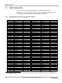
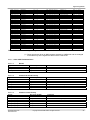
1
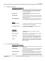
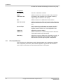
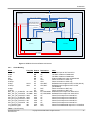
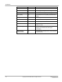
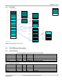
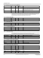
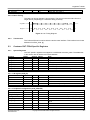
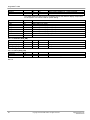
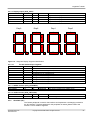
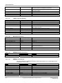
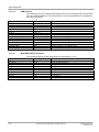
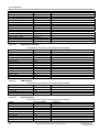
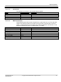
Signal assignments
- Character LCD
the scheduler drives DUT_HUMI_SEGn to 4’b1110 and
DUT_HUMI_LEDn high and enables the DUT_LCD_* interface
control lines.
Should any operation be in progress when the scheduler wishes
to switch back to the LED, then change is halted whilst the
operation completes and any new operation is prevented from
starting (the CharLCD driver appears busy to the processor).
Signal
Direction [Width]
BUTTON
DUT_DSW
DUT_HUMI_An
DUT_HUMI_Bn
DUT_HUMI_Cn
DUT_HUMI_Dn
DUT_HUMI_En
DUT_HUMI_Fn
DUT_HUMI_Gn
DUT_HUMI_DPn
DUT_HUMI_SEGn
DUT_HUMI_LEDn
DUT_LCD_REGSEL
DUT_LCD_RW
DUT_LCD_ENABLE
input[4]
input[4]
bi-dir
bi-dir
bi-dir
bi-dir
bi-dir
bi-dir
bi-dir
bi-dir
output[4]
output
output
output
output
Comments
10.1.2.3
FPGA Configuration connections
These connector is not used by the design, but for FPGA configuration only.
Signal
Direction [Width]
DUTFCP_CLK
DUTFCP_DATA
DUTFCP_PLTXT_RDY
input
input
input
10.1.2.4
Comments
SEMULATOR connections
The SEmulator connector is not used by this design. For further details please refer to the MPB User Guide [1].
Signal
Direction [Width]
SEDUT_L4_RXN
SEDUT_L4_RXP
SEDUT_L4_RXCLKN
SEDUT_L4_RXCLKP
SEDUT_L4_TXN
SEDUT_L4_TXP
SEDUT_L4_TXCLKN
SEDUT_L4_TXCLKP
SEDUT_RESETn
input[4]
input[4]
input
input
input[4]
input[4]
input
input
input
Application Note 218
ARM DAI0218A
Comments
Copyright © 2009 ARM Limited. All rights reserved.
47