1
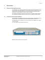
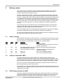
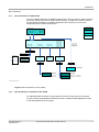
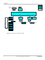
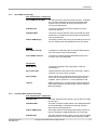
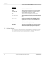
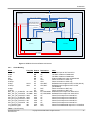
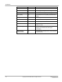
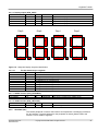
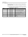
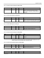
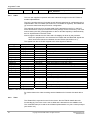
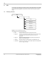
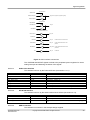
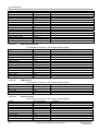
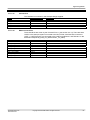
Getting started
2
Getting started
The system comes pre-configured with an example design installed on the customer
FPGA. The processor FPGA is configured and ready for use and the bootmonitor
software is loaded into the system memory.
Connect a serial cable to RS232-4 (UART port3 above the power connector) and use a
terminal emulation program (e.g. HyperTerminal) configured as 38,400 baud, 8bit data,
no parity, 1 stop bit and no flow control to talk to the MPS. Insert the power cable and turn
on the PWR switch at the back. This will bring up the system and the bootmonitor will
start execution. The character display will show the Firmware (F/W) and Hardware (H/W)
versions of the system. This is also output to the serial port for display on the terminal if
connected. The CPU LEDs (0 to 7) will cycle a lighted bit to show the bootmonitor is
running.
The three blue LEDs on the right will be lit to indicate that the system and FPGAs are
configured with valid images. The four green Power LEDs will light to show all power
supplies are functioning properly and within tolerance.
If a FAN LED lights then the corresponding FPGA temperature is above the pre-defined
limit (if fans are fitted then the fan for that FPGA will become operational).
Pressing the recessed reset button on the front panel will perform a hardware reset and
the system will restart as if it had been power cycled.
2.1
Switch settings
The bootmonitor reads the processor switches 1-3 on power up and uses these to select
the boot option. On delivery all the switches are set to ON and defaults to no boot script
with auto detection of semihosting or UART port3 for console interface.
SW1
ON
OFF
SW2
X
X
SW3
X
X
X
ON
ON
X
ON
OFF
X
X
OFF
OFF
ON
OFF
2.2
Function
Normal boot
Run boot Script
Note
Use this as default
This needs to be pre configured from the boot
monitor command line
Auto Select between UART port3 Detects semihosting supported debugger
and Semihosting for Console
Force UART port3 for Console
Always use UART port3 regardless of
semihosting support
Reserved
Do not use, undefined behaviour
Reserved
Do not use, undefined behaviour
Software download to MPS
The MPS comes with a Keil ULINK2 USB JTAG adaptor to allow download and
programming of the Flash memory from µVision. The ULINK2 plugs into the 20way IDC
connector at the back of the unit. Example software and projects are supplied for µVision.
See the µVision documentation for details about how to compile and program the flash.
If you do not use the JTAG download it is possible to transfer files and write them into
flash using bootmonitor and the SD-card slot.
It is possible to fit a SDCard or MMC into the SD-Card slot in the back and access it as a
standard FAT16 8.3 filename device (long filenames are not supported and the maximum
usable card size is 2GB).
2.3
FPGA Image download to MPS
The HPE_Desk application (Windows based) from Gleichmann allows you to download
new FPGA images for the DUT FPGA and updates from ARM for the CPU FPGA (when
available). Please see the Hpe®_desk documentation for details on how to do this.
Application Note 218
ARM DAI0218A
Copyright © 2009 ARM Limited. All rights reserved.
3