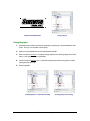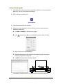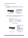
1
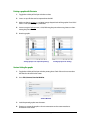
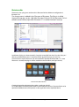
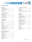
Rev007 WinPlot Welcome Welcome to WinPlot WinPlot is a “bridge” program that allows you to open and either cut or plot the following types of files1: • Adobe Illustrator (*.ai) (legacy version 3.0) • Encapsulated PostScript (*.eps) (vector graphics) • Portable Document Format (*.pdf) (vector graphics) • ISI Design File (*.isi) WinPlot’s advanced integration of the Summa Optical Positioning System (OPOS) simplifies the contour cutting process. Precise contour cutting is now easier than ever! WinPlot Installation Installing WinPlot The Manual/WinPlot CD includes an Autorun file that facilitates the installation. NOTE: Before installing WinPlot on Windows Vista, Windows 7 or Windows 8, make sure that the user has administrative rights and that UAC is deactivated (or set at minimum level). WinPlot/Manual CD When the installation (manual) CD is inserted in the computer, then the autoplay function of Windows starts. Choose to run Windows_Start.exe. Autoplay Windows 7: If autoplay does not start, then hit D is the CD-ROM drive). Autoplay Windows 8: and . Type “D:\windows_start.exe” (where Installation - 1 After that the start-up screen appears. Select the desired language. The following installation window will appear: Click on to start the installation of WinPlot, the latest version will be downloaded from the internet before the installation can be started. If the program is downloaded directly from the internet, then just double click it in explorer to start it. If there is no internet connection available, then click on program can then be installed from the CD by clicking on window. Installation - 2 . The in the new Installing the WinPlot plug-in Plug-ins are available for CorelDraw (from version 12 on) and Adobe Illustrator (from version CS on). • The plug-in for CorelDRAW installs an extra toolbar. This toolbar can be used to add OPOS marks or to automatically exports the current drawing into WinPlot. • The plug-in for Illustrator creates an extra menu under the ‘file menu’ called summa. This menu can be used to add OPOS marks or to automatically exports the current drawing into WinPlot. CorelDRAW Toolbar Script added in Illustrator file menu The plug-in can be installed from the program ‘Summa Cutter Tools’. This program is available on the CD and on the Summa site. NOTE: Before installing Summa Cutter Tools on Windows Vista, Windows 7 or Windows 8, make sure that the user has administrative rights and that UAC is deactivated or set to its minimum level. Installation - 3 Installing Summa Cutter Tools Use the same procedure as with installing WinPlot, however now click on . There exists again the possibility to either install the latest version from the internet or install the version that is on the CD. This installation first puts all the tools on the hard disk, ready for installation. Then it starts the program so that the tools can be installed. It is recommended to install the individual tools directly afterwards. The individual cutter tools can be installed at a later date. However it could be that parts of the installation are blocked by Windows security settings. To start the application later in Windows VISTA and Windows 7 Click on Windows start button and type “cutter tools” (without the quotes) in the search box. Then click on Summa Cutter Tools. For Windows 8 hit the windows key and S simultaneously, then type “cutter tools” (without the quotes) in the search box. Then click on Summa Cutter Tools. It is recommended to click on next without changing any options.. Installation - 4 The Cutter tools program starts up. If more than one version of CorelDRAW or Illustrator is installed, then it is recommended to install the plug-in version per version. In order to do this click on details and choose only one version, then click on the Install tab and click on install to install. Installation - 5 WinPlot Setup Installation of a cutter After WinPlot is installed, it must be configured to work with a Summa cutter. The “Install Cutter” window opens if WinPlot has been started for the first time. If this is the case, then jump to step 3 in procedure below. Installing a cutter or modifying the communication setup of a cutter can only be done when no job is opened. Installing a cutter 1. Start WinPlot. 2. Click Design // Cutters // Install Cutter. 3. Click on your cutter model inside the “Install Cutter” window and then click OK. 4. The next window that will open enables the user to setup the communication port. USB connection is the default connection. This means that no port settings need to be changed if the cutter is installed out of the box , connected via USB and if it is the only cutter connected to the computer. In that case just click on OK, the cutter setup is then finished. Otherwise click on Setup and go to the appropriate procedure described below according to the type of connection. Communication setup - 1 For Ethernet connection Some cutter models can be connected using Ethernet. If the cutter is set up for such a connection, then the used IP address for this connection will be shown on the touch screen of the cutter if media is loaded. Otherwise go in the menu to check the IP address (see cutter manual). 5. Click the on Configure IP. 6. Fill in the correct IP address. Origin Settings Pause Configuration 1 Media size Tool Velocity Knife pressure 50000 x 718 mm Tangential knife 800 mm/s Actions 95 gr Eth. 192.168.2.7 7. Click OK twice. Then change the name of the cutter, this will make it easier for future reference or if more than one cutter is connected. Use the IP address to avoid confusion afterwards. After that Click again OK. Communication setup - 2 For multiple USB connection Up to 4 cutters can be connected to one computer using USB connection. The parameter USB Class in the cutter helps the computer to identify the cutter. The chosen USB Class in the cutter has to be the same as the setting in WinPlot. The USB Class can be seen in the communication menu of the S Class series cutters and in the USB Class menu of the SummaCut series cutters (see cutter manual for details). 5. Click on the drop down box below “Communication Port” and choose the correct USB connection. 6. Click OK. Then change the name of the cutter, this will make it easier for future reference or if more than one cutter is connected. Use the USB Class setting to avoid confusion afterwards. After that Click again OK. . Communication setup - 3 For serial connection Serial connection will either be done through a fixed COM port, or through an adaptor. If it is a fixed COM port, then the COM number is usually 1 or 2. If an adaptor is used, then the number is much higher. This number is set during the installation of the driver for the adaptor. The device manager in Windows can be used to check which COM port have been defined in Windows, however it cannot be used to check which COM port the cutter is connected to. NOTE: Use only COM1 to COM9 for serial connection. The values from COM10 up do not function under certain Windows versions. 5. Select the appropriate COM port from the list. The “Port Settings” will not be grayed-out and can be modified. The default settings are: Baud Rate = 9600 Flow Control = RTS/CTS Parity = None Data Bits = 8 Bits Stop Bits = One The standard settings work with any Summa cutter that is installed out of the box in combination with a Summa serial cable. If another cable is used, then it might be recommended to use Xon/Xoff as setting for Flow Control. 6. Click OK. Then change the name of the cutter, this will make it easier for future reference or if more than one cutter is connected. Use the COM port setting to avoid confusion afterwards. After that Click again OK. Communication setup - 4 WinPlot Transferring a graphic to WinPlot Working with Plug-in The easiest way to get the graphic into WinPlot is using a plug-in, if it exists. Plug-in for Corel The Toolbar in CorelDRAW contains three icons. The first icon is used to set OPOS marks around objects. If the icon is clicked, then following things happen: • A new layer called ‘Regmark’ is created • All objects in all unlocked layers are selected. • OPOS marks of 3mm are put around them and an OPOS XY line is added at the bottom. • The Regmark layer is locked. If the second icon is clicked, then following things happen: • The Regmark layer is temporarily unlocked (just for exporting). • All objects in unlocked layers and in layers where the printing/exporting is not disabled are selected. • All selected objects are exported to a temporarily file and this file is opened in WinPlot. • The Regmark layer is locked. If the third icon is clicked, then following things happen: • All selected objects are exported to a temporarily file and this file is opened in WinPlot. • The Regmark layer is locked. NOTE: Do not use the third icon when doing print and cut jobs, otherwise the marks will not be exported (see procedure in the user manual of WinPlot). After sending the objects to WinPlot, the Regmark layer is locked automatically even if the user unlocked it. Transferring graphic to WinPlot - 1 Plug-in for Illustrator When the plug-in is installed then a script is installed to open WinPlot automatically and import the selected objects into it. Click on File // Summa // Send to WinPlot. The extra menu under file has three sub menu’s. The first sub menu is used to set OPOS marks around objects. Following things happen: • A new layer called ‘Regmark’ is created • All objects in all visible unlocked layers are selected. • OPOS marks of 3mm are put around them and an OPOS XY line is added at the bottom. • The Regmark layer is locked. With the second sub menu following things happen: • A check will occur in order to verify if all changes are saved in the drawing up to the moment where the script is started. If not, the file will be saved automatically. If the file has never been saved, then Illustrator will prompt the user for a file name. • The Regmark layer is temporarily unlocked (just for saving). • All objects in in all visible layers are selected. • All selected objects are saved to a temporarily file and this file is opened in WinPlot. With the third sub menu following things happen: • A check will occur in order to verify if all changes are saved in the drawing up to the moment where the script is started. If not, the file will be saved automatically. If the file has never been saved, then Illustrator will prompt the user for a file name. • All selected objects are saved to a temporarily file and this file is opened in WinPlot. NOTE: The revert command in Illustrator does not work anymore straight after the design has been sent to WinPlot. Transferring graphic to WinPlot - 2 Exporting a Graphic by hand Exporting from CorelDraw for WinPlot Make sure all objects are outlines and not filled (if objects are both filled and have an outline with a color, then all objects will appear twice upon one another in WinPlot and thus be cut twice). Click on File // Export. Choose as type eps. Make sure that in the export filter the option convert text to curves is checked. It is also recommended to set post script level to level2. Exporting from Illustrator for WinPlot Make sure all objects are outlines and preferably not filled. Select all text and click on Type // Create outlines. It is also recommended to make sure that the text is either filled or has a colored outline with a hairline thickness, not both at the same time. Make sure to export to the correct version of Adobe Illustrator. For Illustrator versions up to 10: click on File // Save As. In the Illustrator Native Format Options window, choose Illustrator 7. For Illustrator versions CS: click on File // Export. Choose as file type Adobe Illustrator Legacy. In the Illustrator Legacy Options window, choose Illustrator 3. For Illustrator versions CS2 on: click on File // Save As. Choose as file type Adobe Illustrator. In the Illustrator Options window, choose Illustrator 3. Exporting from Inkscape NOTE: The procedure below was written with the latest stable version of the program (0.91) r13725 that was available at the time this paragraph was written. Inkscape is free and open source software. Because of that Summa cannot guarantee that future versions will stay compatible. Make sure all objects are outlines and not filled (if objects have both a fill color and a stroke color, then all objects will appear twice upon one another in WinPlot and thus be cut twice). Click on File // Save As. Choose as type pdf. Use the default pdf settings. Transferring graphic to WinPlot - 3 Exporting from FreeHand for WinPlot Make sure all objects are outlines and preferably not filled. Select all text and click Text // Convert to paths. It is also recommended to make sure that the text is either filled or has a colored outline with a hairline thickness, not both at the same time. Click on File // Export. Choose as type ai. In The Export Document window choose Adobe Illustrator 3.0/4.0. Using another design program Make sure all objects are outlines and not filled. Text has to be converted to curves or they will not show up in WinPlot. If the text is converted to curves while designing, then choose to export as an adobe illustrator file (ai) version 3 if possible. If converting text to curves is used while exporting, then convert text to curves in the eps export filter. Use postscript level 1 if possible. Importing a graphic in WinPlot 1. Start WinPlot. 2. Click Design // Open… The “Open” window appears. 3. Set file type to the same type as chosen while exporting the design. 4. Navigate to the file that was saved or exported in the design software. 5. Open the file. Transferring graphic to WinPlot - 4 WinPlot Cutting a graphic The following procedure lists the basics about cutting a graphic. New Roll The new roll icon can be used to define a new working space on the roll of vinyl. It is used when a new roll is loaded or to advance beyond a job that has been cut. The way the program reacts after clicking on that icon depends on what the program has already done. If a job has already been sent to the cutter and the feed option was not chosen (see output setup details options below), then WinPlot will ask the user whether or not the media has to be transported to the end of the previous job. Select ‘YES’ to move to the end to move the media to the end of the job. Click on ‘NO’ if it is not necessary. NOTE: If ‘NO’ is clicked, then the user has to load new media or move the media forwards himself. If ‘Yes’ is clicked and new media was already loaded or the media was already moved forward by the user, then the cutter will feed the media forward for the length of the previous job without cutting, thus wasting media when it starts the next job. If more than one cutter is installed, then WinPlot will ask to select the desired cutter. Click if necessary on the desired cuter. Finally a window will open with the width and length of the current loaded media. Click OK. The values can be changed, it is however not recommended to do so. Any value that is filled in will be used as a maximum value for width or length until WinPlot is closed and opened again. Cutting a graphic - 1 Cutting a graphic Click to send the graphic to the cutter. The “Output Setup Details” window opens. It has four tabs. First tab The cutter tab displays the cutter that has been selected and the port it is connected to. The second tab Some options may be disabled (grayed out) out depending on the setting of other options. General: Set the number of ‘Copies’ if more than one copy needs to be cut out. The distance between the copies is fixed at 2mm. If Autorotate is checked, then the program rotates the copies if this will use less vinyl. Check the ‘Cut red lines in FlexCut mode’ to enable FlexCut (see cutter user manual for more info on FlexCut). NOTE: “red” lines means that lines are created as 100% Magenta and 100% yellow in a CMYK space (those objects will have color: ). NOTE: “red lines” have 2 functions for cutter model with a dual head ( extra pen holder, - no OPOS function) If the parameter tool is set at “extra pen” => plotting is first done with the extra pen, then the red lines are cut with the tangential knife in FlexCut mode If the parameter tool is set at “tangential knife” => cutting is first done with the tangential knife, red lines are then plotted with an extra pen. ‘OPOS sheet mode’ is only available for OPOS jobs (see OPOS sheet mode). Cutting a graphic - 2 Feed Click on ‘No Feed 'to activate the internal nesting option of WinPlot (see Nesting). NOTE: If a new roll is loaded or if the origin is manually changed after/during nesting, then click on before sending data to the cutter and choose ‘No’ if asked to move the origin. Click on ‘Feed after job’ to move the media forward after the job is cut. A new origin will then be defined after the job. ‘Feed after copy’ does the same, but now after each copy (when multiple copies are asked for). NOTE: If the box in front off ‘Cut red lines in FlexCut mode’ is checked, then the feed option is automatically set to ‘Feed after Copy’ NOTE: The feed options are disabled for OPOS jobs. Check ‘Cut after feed ‘ If the media has to be cut off after the job. The S Class cutters will use the cut off knife to cut the media after the job/copy. The SummaCut R series will use a FlexCut line to cut the media after the job/copy. Older models will ignore this command. A new origin will then be defined. The distance between the job and the cut line can be set by using the cutter parameter ‘Cut off margin’ this parameter can be changed on the cutter. Weeding box This option allows the user to add a rectangle around the bounding box of the job at a selectable distance (set in Weed size). This rectangle will then be cut together with the job. This option is grayed out for OPOS jobs. Tiling This option is used if the width of the design is larger than the width of the loaded media. Therefore this option will be grayed out if the media is wider than the job. The size of the tile and also the overlap can be set. Tiles can be cut out separately also. The tiles are numbered from bottom to top and from left to right. 2 1 4 3 Cutting a graphic - 3 6 5 The third tab The third tab is used if not all objects need to be cut. Click on ‘Design’ to cut out everything. If ‘Current Selection’ is chosen, then only the selected objects will be cut out. The third option makes it possible to cut by colour. Just choose one object in a certain colour. Then click on ‘Colour in Selection’. All objects that have that colour will be cut. There exists also the possibility to choose more than one colour. When the job is an OPOS job, then there also the choice to cut out the OPOS marks or not. The fourth tab The fourth tab show the sorting options. Sorting mode If ‘Keep design order’ is chosen, then WinPlot cuts out the objects in the same order they were created in the design software. This can result in the media moving a lot back and forth. Click ‘Least media movement’ to enable sorting. Check the box ‘Inside objects first’ to make sure that the little details inside larger objects are cut first, independent of the order they were created. Objects startpoints This option optimizes the starting point for closed curves. This is used when the users sees that the curves randomly do not close as they should. Cutting a graphic - 4 Nesting To conserve material, WinPlot evaluates the size of each graphic and determines whether it can be cut out of material left over from previous cuts. In the following example, two copies of a graphic have been cut side by side in the material (1). WinPlot then places the next two copies in a row above the first (2). The next graphic is small enough so WinPlot can place it in the uncut material to the left of the larger graphics (3, 4). This feature will work if… No Feed is chosen in the output option menu The “New Roll” button ( WinPlot was not closed between cuts. The cutter’s origin was not moved using the cutter’s keypad. ) has not been clicked. Graphic placement Cutting a graphic - 5 WinPlot OPOS contour cutting Using OPOS plug-in With Corel Creating the graphic 1. Use design software to create the graphic that needs to be print and cut. It is recommended to work with layers so that the print data is in one layer and the cut lines are in another layer. Graphic to be printed and cut Usage of layers 2. Insert OPOS registration marks around the graphic using the plug-in. Click on the Mark icon. Inserting marks OPOS contour cutting - 1 Graphic with OPOS marks Usage of layers Printing the graphic 1. Disable the layer with the cut data for exporting or printing (it is recommended to hide it also. This way a visual check can be done). 2. Export to an eps/pdf file that can be imported into the RIP. 3. Make sure there is at least a 1 cm (0.4in) margin beyond each of the graphic’s four OPOS marks. A 2cm (0.8in) margin is preferable. 4. Leave a margin of at least 4 cm (1.57in) following the print when using sheets or when cutting the print off a roll. 5. Print the graphic. Setting up layers to export for printing OPOS contour cutting - 2 Setting up layers for cutting Contour Cutting the graphic 1. Disable the layer with the print data for exporting or printing ( it is recommended to hide it also. This way a visual check can be done). 2. Click on the send to WinPlot icon. Send to WinPlot 3. Load the printed graphic into the cutter. 4. If necessary, rotate the graphic so that its orientation on the screen matches its orientation in the cutter. A. Click Edit // Select All to select the entire graphic. B. Click and then press N on your keyboard, the rotate window will open. C. Place a check mark in the Preview box. D. Click the radio buttons for the 8 degree values until the graphic’s orientation matches its orientation in the cutter. E. Click OK when the graphic is properly oriented. The graphic’s orientation on the screen must match its orientation in the cutter OPOS contour cutting - 3 5. Click to send the graphic to the cutter. The “Output Setup Details” window opens (see previous paragraph for detailed description) 6. Change the output options if necessary, then click Send to Cutter. The cutter’s LCD displays “Set knife above first marker”. 7. Using the cutter’s four navigation keys positions the knife above the graphic’s origin marker (the marker at the bottom right-hand corner of the graphic). 8. Press the cutter’s “Enter” key. The cutter will register the OPOS marks and then cut out the graphic. OPOS contour cutting - 4 Using OPOS plug-in With Illustrator Creating the graphic 1. Use your design software to create the graphic that you want to print and cut. It is recommended to work with layers so that the print data is in one layer and the cut lines are in another layer. Graphic to be printed and cut Usage of layers 2. Insert OPOS registration marks around the graphic using the plug-in. Click on the Mark icon in Corel. Or go to File //Summa//Add OPOS XY Regmarks for Illustrator Inserting marks in Illustrator Graphic with OPOS marks OPOS contour cutting - 5 Usage of layers Printing a graphic with Illustrator 1. Toggle the visibility of the layer with the cut data. 2. Save as an eps file that can be imported into the RIP. 3. Make sure there is at least a 1 cm (0.4in) margin beyond each of the graphic’s four OPOS marks. A 2cm (0.8in) margin is preferable. 4. Leave a margin of at least 4 cm (1.57in) following the print when using sheets or when cutting the print off a roll. 5. Print the graphic. Setting up layers to export for printing Setting up layers for cutting Contour Cutting the graphic 1. Toggle the visibility of the layer with the printing data. Check if that is the correct data that needs to be send to the cutter. 2. Go to File//Summa//Send to WinPlot. Send to WinPlot 3. Load the printed graphic into the cutter. 4. If necessary, rotate the graphic so that its orientation on the screen matches its orientation in the cutter. OPOS contour cutting - 6 F. Click Edit // Select All to select the entire graphic. G. Click and then press N on your keyboard, the rotate window will open. H. Place a check mark in the Preview box. I. Click the radio buttons for the 8 degree values until the graphic’s orientation matches its orientation in the cutter. J. Click OK when the graphic is properly oriented. The graphic’s orientation on the screen must match its orientation in the cutter 5. Click to send the graphic to the cutter. The “Output Setup Details” window 6. Change the output options if necessary, then click Send to Cutter. The cutter’s LCD displays “Set knife above first marker”. 7. Using the cutter’s four navigation keys, position the knife above the graphic’s origin marker (the marker at the bottom right-hand corner of the graphic). 8. Press the cutter’s “Enter” key. The cutter will register the OPOS marks and then cut out the graphic. OPOS contour cutting - 7 Illustrator on Mac There exists also a plug-in to set the marks in Illustrator for Mac. Minimum configuration is Illustrator CS4. The Summa menu is added in the File menu of Illustrator. The Plug-in is called SummaCS4mac.aip, version 1.0.0.0 for Illustrator CS4 and CS5, for Illustrator CS6 it is called SummaCS6mac.aip and for Illustrator CC is it called SummaCCmac.aip. PLUG-IN FOR ILLUSTRATOR MAC Installation of plug-in is done manually. Copy the correct file from the CD to the “plug-ins” directory of Adobe Illustrator CS (SummaCS4mac.aip for Illustrator CS4 and CS5 – SummaCS6mac.aip for Illustrator CS6 and SummaCCmac.aip for Illustrator CC ). Once Illustrator is started, the plug-in will be available in the File menu (see figure above). PLUG-IN DIRECTORY FOR MAC Creating the graphic and printing the graphic is analogue as for PC. To cut the contour, the file has to be saved as an illustrator file version 3. Then this file has to be opened in WinPlot, the rest of the process is then again the same as explained above. OPOS contour cutting - 8 OPOS sheet mode If the same graphic design has been printed on a multiple sheets, then this feature can be used. NOTE: The sheets should be more or less the same size, and the graphics on them should be oriented and positioned the same way. 1. Load the media. Use easy orientation points to be able to quickly position the sheet. In the figure below, a rim of the base plate and the side of the pinch roller assembly are used to align the sheets. 2. If necessary, rotate the graphic in WinPlot so that its orientation on the screen matches the orientation of the job loaded in the cutter. 3. Send the job to the cutter by clicking on . Make sure OPOS sheet is checked. 4. Change the output options if necessary, then click Send to Cutter. The cutter’s LCD displays “Set knife above first marker”. OPOS contour cutting - 9 5. Using the cutter’s four navigation keys positions the knife above the graphic’s origin marker (the marker at the bottom right-hand corner of the graphic). 6. Press the cutter’s “Enter” key. The cutter will stop after the first contour has been cut and come online again. 7. Raise the pinch rollers and manually remove the sheet. 8. Insert the next sheet into the cutter. Lower the pinch rollers. NOTE: The second and any following sheets must be loaded in the cutter at the same position as and with the same orientation of the first sheet. When in OPOS sheet mode, the cutter stores the distance between edges of the sheet and the first OPOS mark. Copyright Summa. OPOS contour cutting - 10