1
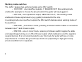
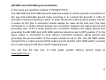
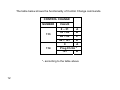
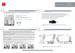
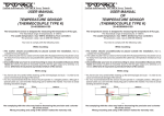
1
Version 1.0
Table of contents
Structure __________________________________________________________ 3
Power supply ______________________________________________________ 5
Control Ground Lift (CTRL GND) switch ________________________________ 5
Working mode switches _____________________________________________ 6
Way of connecting __________________________________________________ 7
AB GND and ACD GND ground switches _______________________________ 9
MIDI functions_____________________________________________________ 10
Technical parameters ______________________________________________ 13
FCC Compliance___________________________________________________ 14
Declaration of Conformity ___________________________________________ 15
1
Dear Customer!
Thank you for choosing our product.
LINE MIDI SWITCHER (LMS-1) is a bidirectional, passive switcher of the audio signal
with galvanic separation between A, B, C, D outputs/inputs. The LMS-1 can be used as
amps switcher in “one of four” mode (guitar connected to an input of selected amp)
without occurring of the ground loops. The LMS-1 is controlled via MIDI interface and
buttons on the top of the device.
Basic features:
- working modes:
1) one IN input – four A,B,C,D outputs,
2) four A,B,C,D inputs – one OUT output,
- signalization of the power supply and connections state,
- four buttons for manual control,
- fully passive signal path (without active components and separating transformers)
assuring no influence of the switcher on the guitar sound
- switching based on the electro mechanic relays with silent switching system,
- ground connections optimization switchers,
- MIDI THRU connector,
- 9V DC power supply
2
Structure
1234567-
output/input D
ACD GND grounds switch
output/input C
DS1 and DS2 – working mode switches
MIDI channel settings switch
output/input B
AB GND grounds’ switch
8910 11 12 13 -
output/input A
input/output Y
CTRL GND ground switch
9V power supply connector
MIDI IN input
MIDI THRU output
3
14 15 16 17 18 4
power supply indicator
A output/input activity indicator
A output/input „ON” switch
B output/input activity indicator
B output/input „ON” switch
19 20 21 22 -
C output/input „ON” switch
C output/input activity indicator
D output/input „ON” switch
D output/input activity indicator
Power supply
LMS-1 should be supplied from 9V (DC) regulated source with capacity 100 mA or
more. Before plugging the power supply please check the pin polarization.
The device is protected against opposite polarity. If this protection switches on it is
needed to disconnect the power supply and wait few minutes before reactivation of the
device.
ATTENTION: Damages caused by improper power supply causes the loss of the
warranty.
Control Ground Lift (CTRL GND) switch
If the 9V power supply is fully separated (not connected with signal ground or
grounding) the CTRL GND switch should be set to ON position. If the 9V negative wire
is connected with other signal ground or grounding the Control Ground Lift switch
should be set to OFF.
5
Working mode switches
The LMS-1 posses two working modes set by DS1 switch
- DS1=OFF, one input/four outputs, Y IN/ABCD OUT, this working mode
enables for example to choose the amp to which the guitar will be plugged in
- DS1=ON, four inputs/one output, ABCD IN/Y OUT, this working mode
enables to choose signal source (e.g. guitar) connected to the amp.
In working mode one input/four outputs the DS2 switch decides about working mode of
the switches:
- DS2=OFF, „one of four” mode, pressing of chosen switch makes a connection
between input Y and chosen output,
- DS2=ON, „one or more” mode, pressing of chosen switch toggles the state
(correspondingly turning on or off) of chosen output what enables to send the signal to
several devices. It is not recommended to use this mode for guitar with two or more
amps because it creates the ground loop which can (especially on high gain tones)
provoke audible hum in speakers.
6
Way of connecting
Scheme No. 1 (on the inside front cover of the manual) shows the way of connecting in
mode one input – four outputs (Y IN/ABCD OUT).
Scheme No. 2 (on the inside back cover of the manual) shows the way of connecting in
mode four inputs – one output (ABCD IN/Y OUT).
The scheme on next page shows the use of two Line Midi Switchers for preamps
switching, especially those of them possessing the connection between signal ground
and grounding. In both of LMS-1 switchers should be set the same MIDI channel what
will assure synchronic switching.
7
8
AB GND and ACD GND ground switches
In the mode one input/four outputs (Y IN/ABCD OUT).
The AB GND and ACD GND grounds switches enable to set the grounds connections in
the way that eliminates ground loops occurring or to connect the grounds in order to
eliminate hums and switching noises. In order the device works properly always use the
A output at first (the A connector should always be used as the first one) The amp
connected to A output should posses the connection between the signal ground and
grounding wire. If all of amps posses the connection between the signal ground and
grounding the AB GND and ACD GND switches should be set to OFF position. If to the
given output is connected an amp without connection between signal ground and
grounding the ground switch of this output should be set to ON. The AB GND switch
connects the A output ground with B output ground and the ACD GND switch connects
the A output ground with the C and D outputs ground.
You will find the tips how to build guitar system without ground loops at
www.glab.com.pl.
9
In the mode four inputs/one output (ABCD IN/Y OUT).
When the guitars (or other signal sources not connected to the grounding) are
connected to the ABCD inputs the AB GND and ACD GND switches should be set to
ON position.
MIDI functions
To set the MIDI channel on which the LMS-1 receives the commands serves the MIDI
CHANNEL rotatable knob. To switch the channel use the small screwdriver to turn
smoothly central part of the switcher to the right or to the left. The arrow-head indicates
set channel.
The LMS-1 can be controlled via Program Change and Control Change commands.
10
The table below shows the functionality of Program Change commands.
Prog
Ch No
1
2
3
4
5
6
7
8
9
10
A
ON
ON
ON
ON
-
OUT/IN
B
C
ON
ON
ON
ON
ON
ON
ON ON
D
ON
-
Prog
Ch No
11
12
13
14
15
16
17
18
19
A
ON
ON
ON
ON
ON
OUT/IN
B
C
ON ON
ON
ON
ON
ON
ON ON
ON ON
D
ON
ON
ON
ON
ON
ON
ON
ON
Prog Ch No = 4+1(when A=ON)+2(when B=ON)+4(when C=ON)+8(when D=ON)
11
The table below shows the functionality of Control Change commands.
CONTROL CHANGE
NUMBER
113
114
VALUE
0 – 31
A
32 – 63
B
64 – 95
C
96 – 127
D
0
A
Prog Ch No *
127
B
*- according to the table above
12
Technical parameters
Dimensions:
width
205 mm
depth
70 mm
height
38 mm
Weight
Maximal input signal
0,45 kg
30 dBu
Power supply
9V DC (8,6 up to 9,5V regulated)
Current consumption
100 mA
13
FCC Compliance
This device complies with Part 15 of the FCC Rules. Operation is subject to
the following two conditions: (1) this device may not cause harmful interference, and (2)
this device must accept any interference received, including interference that may cause
undesired operation.
NOTE: This equipment has been tested and found to comply with the limits for a Class
B digital device, pursuant to Part 15 of the FCC Rules. These limits are designed
to provide reasonable protection against harmful interference in a residential installation.
This equipment generates, uses and can radiate radio frequency energy and, if not
installed and used in accordance with the instructions, may cause harmful interference
to radio communications. However, there is no guarantee that interference will not occur
in a particular installation.
If this equipment does cause harmful interference to radio or television reception, which
can be determined by turning the equipment off and on, the user is encouraged to try
to correct the interference by one or more of the following measures:
– Reorient or relocate the receiving antenna.
– Increase the separation between the equipment and receiver.
– Connect the equipment into an outlet on a circuit different from that to which the
receiver is connected.
– Consult the dealer for help.
14
Declaration of Conformity
ELZAB S.A., ul. Kruczkowskiego 39, 41-813 Zabrze, Poland,
declare under sole responsibility, that the following product:
G LAB Line Midi Switcher LMS-1
conforms with requirements of the EC Council Directives:
● 2006/95/EEC Low Voltage Directive,
● 2004/108/EEC Electromagnetic Compatibility,
and holds CE mark. Above named product conforms with the following standards:
● PN-EN 60065:2004 /EN 60065:2002/ Audio, video and similar apparatus Safety requirements.
● PN-EN 55103-1:2000 /EN 55103-1:1996/ Electromagnetic compatibility Product family standard for audio, video, audio-visual and entertainment
lighting control apparatus for professional use - Part 1: Emission
● PN-EN 55103-2:2001 /EN 55103-2:1996/ Electromagnetic compatibility Product family standard for audio, video, audio-visual and entertainment
lighting control apparatus for professional use - Part 2: Immunity
Jerzy Biernat
President of the ELZAB S.A. Board of Directors
Copy of original EC declaration of conformity is available for download on our
webside http://www.glab.com.pl
15
DO NOT PLACE THIS PRODUCT INTO THE WASTE CONTAINER !
This device is marked with a cross-lined waste container symbol
according to 2002/96/EU Directive on Waste Electric
and Electronic Equipment.
Such marking informs that after usage equipment can not be
trashed together with other household waste.
An user obligation is to return wasted equipment to a party collecting wasted
electric and electronic equipment. Parties collecting such equipment organize
a system, including local collection points, shops and other units, allowing
to return such equipment. This Directive assures an user free of charge
utilization of such delivered equipment.
This device is made of materials which can be recycled or utilized after
becoming out of use. Proper handling of wasted electric and electronic
equipment reduce demand for row materials and contribute in avoiding harmful
consequences for environment and health of people caused by dangerous
components and not proper storing and utilizing of such equipment.
User’s manual Drawing No. G76INA00
16
2