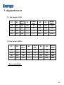
1
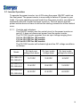
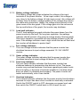
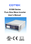
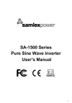
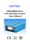
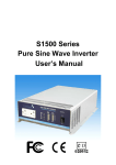
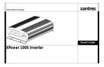
PureSine 1500
User’s Manual
Sinergex Technologies L.L.C. (USA)
Website: www.sinergex.com
Email: [email protected]
List of contents
1.
2.
3.
4.
5.
6.
Important safety striations
1-1 General safety precautions………………………………………………
1-2 Precautions when working with batteries………………………………
Features
2-1 Application…………………………………………………………………..
2-2 Electrical performance……………………………………………………..
2-3 Mechanical drawings………………………………………………………
Introduction
3-1 Front panel operations …………………………………………………….
3-2 Rear panel operations………..……………………………………………
3-3 Installation……………………………………………………………………
3-4 Quick hook – up and testing……………………………………………….
3-5 AC safety grounding……………………………………………………….
3-6 Making DC wire connections……………………………………………
1
2
3
4
5
6~7
7
8
9~10
11
12~13
3-7 Inverter operation…………...……………………………………………… 14~15
3-8 Power output……………………………………………………………….. 16
Troubleshooting guide…………………………………………………..………. 17~18
Maintenance………………………………………………….……………………. 19
Warranty……………………………………………………………….……………. 19
7.
Appendices A
7-1 Dip switch (110V)…………………………………………………………… 20
7-2 Dip switch (220V)……………………………………………………..…… 20
8.
Appendices B
8-1 Operations of RS232 serial port…………………………………………..
21
8-2 Interface command …………………………………………….………….. 22~26
9.
Appendices C
9-1 Remote control operations……………………………………………….
27~28
9-2 Power Saving mode………………………………………………………… 29~32
1. Important Safety Instructions
WARNING!
Before you install and use your PS-1500, be sure to read and
Save these safety instructions.
1-1. General Safety Precautions
1-1-1. Do not expose the PS-1500 Inverter to rain, snow, spray, bilge or
dust. To reduce the risk of hazard, do not cover or obstruct the
ventilation openings. Allow good air flow to the inverter.
Do not install the PS-1500 Inverter in a zero-clearance
compartment. Overheating may result.
1-1-2. To avoid the risk of fire and electric shock, make sure the existing
wiring is in good electrical condition and that wire size is not
undersized.
Do not operate the PS-1500 Inverter with damaged or substandard
wiring.
1-1-3. This equipment contains components which can produce arcs or
sparks. To prevent fire or explosion do not install in compartments
containing batteries or flammable materials or in locations that
require ignition protected equipment.
This includes any space containing gasoline-powered machinery,
fuel tanks, or joints, fittings, or other connections between
components of a fuel system.
1
1-2. Precautions When Working with Batteries
1-2-1. If battery acid contacts skin or clothing, wash immediately with soap
and water.
If acid enters eyes, immediately flood eye with running cold water for
at least 20 minutes and get immediate medical attention.
1-2-2. NEVER smoke or allow a spark or flame in vicinity of battery or
engine.
1-2-3. Do not drop a metal tool on the battery.
The resulting spark or short-circuit on the battery or other electrical
parts may cause for or an explosion.
1-2-4. Remove personal metal items such as rings, bracelets, necklaces,
and watches when working with a lead-acid battery.
A lead-acid battery produces a short-circuit current high enough to
weld a ring or alike to metal, causing severe burns.
2
2. Features
• Pure sine wave output (< 3% THD)
• Output frequency: 50/60Hz switch table.
• Low power “ Power Saving Mode “ to conserve energy.
• RS – 232C interface / remote controls port
• Built–in voltage and watt meter.
• Thermostatically controlled cooling fan.
• Advanced microprocessor design.
• Protection: • Input low voltage
• Overload
• Short circuit
• Low battery alarm
• Input over voltage • Over temperature
2-1. Application
2-1-1.
Power tools, circular saws, drills, grinders, sanders, jigsaws, weed and
hedge trimmers, air compressors.
2-1-2.
Office equipment, computers, printers, monitors, facsimile machines,
scanners etc.
2-1-3.
Household items, vacuum cleaners, fans, fluorescent and incandescent
lights, shavers, sewing machines, etc.
2-1-4.
Kitchen Items, microwave ovens, refrigerators and freezers, coffee
makers, blenders, ice makers, toasters, etc.
2-1-5.
Home entertainment electronics, televisions, VCRs, DVD players, video
games, musical instruments, satellite equipment, Hi Fi equipment, etc.
2-1-6.
Industrial equipment, work lights, etc.
3
2-2. Electrical Performance
Specification
Model No.
Item
PS-1500-1 PS-1500-1 PS-1500-1 PS-1500-2 PS-1500-2 PS-1500-2
12
24
48
12
24
48
Continuous Output Power
1500W
Surge Rating
2000W
Input Voltage
Output Voltage
12V
24V
100 / 110 / 115 / 120V
Frequency
(Switch Selectable)
12V
± 3%
48V
200 / 220 / 230 / 240V
25A
± 3%
85%
87%
11A
88%
86%
No Load Current Draw
1.5W Saving Mode
Output Waveform
Sine Wave <3% THD
Output Voltage Regulation
24V
50/60Hz +/- 0.05%
Peak Output Current
Efficiency (full load)
48V
100 / 110 / 115 / 120V
RMS –10%/+4%
89%
90%
200 / 220 / 230 / 240V
RMS –10%/+4%
Input Voltage Regulation
10-16 VDC 20-32 VDC 42-62 VDC 10-16 VDC 20-32 VDC 42-62 VDC
Protection
Overload, Short Circuit, Reverse Polarity (Fuse), Over/Under Input
Voltage, Over Temperature.
Power Saving Recovery
Time
5 Second
Interface Control Port
RS-232C With Baud Rate 1200, 2400, 4800 (Switch Selectable)
Remote Control Unit
Optional
Safety
UL458
EN60950
EN50081-1:1992
EN50082-1:1992
EMC
FCC Class B
e-Mark
EN55022B:1994
EN61000-4-2:1995
e13-020932
EN61000-4-3:1996
ENV50204:1995
Operating Temperature
Range
0-40
Storage Temperature Range
-30 to 70
Dimensions
390 (L) x 275 (W) x 105 (H) mm / 15.4 (L) x 10.8 (W) x 4.1 (H) Inch
Cooling
Thermostatically controlled cooling fan
Weight
7.0kgs / 15.5 lbs.
4
2-3. Mechanical Drawings
5
3. Introduction:
The Sinergex PureSine power inverters are some of the most advanced mobile
power products available. To get the most out of your PureSine 1500, it must be
installed and used correctly. Please read the instructions in this manual before
installing and using the inverter.
3-1. Front Panel Operation :
3-1-1. Front View:
3-1-2.
ON/OFF Switch:
Power ON/OFF switch. Leave in OFF position during installation.
3-1-3.
Power Saving : Power energy saving enable.
OVP; Over Voltage Protection
UVP: Under Voltage Protection
OTP: Over Thermal/Heating Protection
OLP: Over Load Protection
Input Volts: Input Voltage Display
Load Watts: AC Load Wattage Display
6
3-1-4. AC outlet (Outlet sockets available):
North America (GFCI )
North America
Continental European (Schuko)
Australia / New Zealand
United Kingdom
3-2. Rear Panel Operation :
3-2-1. Ventilation Openings:
Do not obstruct. Allow at least 1 inch for air flow.
3-2-2. Battery terminals:
Connect to 12V / 24V / 48V battery or other 12V / 24V / 48V power
source.
RED is positive, BLACK is negative. Reverse polarity connection will
blow internal fuse and may damage inverter permanently.
3-2-3. RS-232C:
Connect to remote control unit (optional accessory) or control
remotely by computer.
3-2-4. Connect chassis ground terminal to earth or to vehicle chassis using
8 AWG wire.
WARNING!
Operation of the inverter without a proper ground
connection may result in an electrical safety hazard.
7
WARNING!
Shock Hazard. Before proceeding further, carefully
Check the inverter is NOT connected to any batteries
and all wiring is disconnected from any electrical
sources. Do no connect the output terminals of the
PS-1500 Inverter to an incoming AC source.
3-3. Installation:
Where to install. The power inverter should be installed in a location that
meets the following requirements:
3-3-1. Dry – Do not allow liquid to drip or splash on the inverter.
3-3-2. Cool – Ambient air temperature should be between 0 and 40 degrees
Celcius. The cooler the environment the better.
3-3-3. Safe – Do not install in a battery compartment or other areas where
flammable fumes may exist, such as fuel storage areas or engine
compartments.
3-3-4. Ventilated – Allow at least one inch of clearance around the inverter
for air flow. Ensure the ventilation openings on the rear and bottom
of the unit are not obstructed.
3-3-5. Dust-Free – Do not install the PS-1500 Inverter in dusty environments
where contaminants such as dust, wood particles or other filings or
shavings. These particles can be pulled into the unit when the fan is
operating.
3-3-6. Close to batteries – Avoid excessive cable lengths but do not
install the PS-1500 Inverter in the same compartment as batteries.
Use the recommended wire lengths and sizes (see section 2-10 ).
Also do not install the inverter where it will be exposed to the
gases produced by the battery. These gases are very corrosive and
prolonged exposure will damage the PS-1500 Inverter.
8
3-4. Quick hook – up and testing:
For a quick hook-up and test of the inverter to check its performance
before final installation, please follow these guidelines:
3-4-1. Unpack and inspect the power inverter. Check to see that the power
switch is in the OFF position.
3-4-2. Connect the cables to the power input terminals on the rear panel of
power inverter .
The red terminal is positive (+) and black terminal is negative (-).
Insert the cables into the terminals and tighten wires securely.
WARNING!
Make sure the DC terminal connections are tight and
secure. (torque to 9-10 ft-lbs, 11.7-13Nm). Loose
connections will overheat and could result in a potential
hazard.
3-4-3. Before proceeding further, carefully check that you have connected
ables to the DC terminals correctly. That is the RED cable to the
positive (+) terminal and the black cable to the negative (-) terminal.
CAUTION !
and may cause permanent damage to the inverter.
Damage caused by reverse polarity is not covered
by warranty.
9
3-4-4. Connect the cable from the negative terminal of the inverter to the
negative terminal of the power source. Make a secure connection.
WARNING !
You may observe a spark when you make the
connection since current may flow to charge
capacitors within the inverter. Do not connect the
inverter to your power source in the presence of
flammable fumes. Explosion or fire may result.
3-4-5. Set the power switch to the ON position. Check the meters and
indicators on the front panel of the inverter. The voltage bar graph
should indicate 11 to 14 volts (22 to 28V when 24V version is used)
depending on the voltage of the power source. If it does not, check
your power source and the connections to inverter.
All other indicators should be off.
3-4-6. Set the power inverter switch to the OFF position, the indicator lights
may blink and the internal alarm may sound momentarily.
The is normal. Plug the test load into the AC receptacle on the
front panel of the inverter.
3-4-7. Set the power inverter switch to the ON position and turn the test
load ON. The inverter should supply power to the load.
If you plan to accurately measure the true output r.m.s. voltage of
inverter, a meter such as FLUKE 45 BECKMAN 4410 or TRIPLETT
4200 must be used.
10
3-5. AC Safety Grounding:
During the AC wiring installation, AC input and output ground wires
are connected to the inverter. The AC input ground wire must connect
to the incoming ground from your AC utility source.
The AC output ground wire should go to the grounding point for your
loads (for example, a distribution panel ground bus ).
3-5-1. Neutral Grounding (GFCI’S):
3-5-1-1. 120V models: The neutral conductor of the AC output circuit
of the PS-1500 Inverter is automatically connected to the
safety ground during inverter operation. This conforms to
National Electrical Code requirements that separately derived
AC sources (such as inverter and generators) have their
neutral conductors tied to ground in the same way that the
neutral conductor from the utility is tied to ground at the AC
breaker panel. For models configured with a transfer relay,
while AC utility power is present and the PS-1500 Inverter is
in bypass mode, this connection (neutral of the PS-1500
Inverter’s AC output to input safety ground) is not present so
that the utility neutral is only connected to ground at your
breaker panel, as required.
3-5-1-2. 230V models: There is no connection made inside the
PS-1500 Inverter from either the line or neutral conductor to
the safety ground.
11
Ground Fault Circuit Interrupters (GFCI):
Installations in Recreational Vehicles (for North American approvals) will require
GFCI protection of all branch circuit connected to the AC output of the
hardwire terminal equipped PS-1500 Inverter. In addition, electrical codes require
GFCI protection of certain receptacles in residential installations. While the pure
sine wave output of the PS-1500 Inverter is equivalent to the waveform provided by
utilities, compliance with UL standards requires us to test and recommend specific
GFCI. Our Company has tested the following GFCI-protected 20A receptacles
and found that they functioned properly when connected to the output of the
PS-1500 Inverter.
WARNING !
Do not operate the power inverter without
Connecting to ground.
Electrical shock me result.
3-6. Making DC Wiring Connections :
Follow this procedure to connect the battery cables to the DC input terminals
on the PS-1500 Inverter. Your cables should be as short as possible (ideally,
less than 10 feet / 3 meters ) and large enough to handle the required
current in accordance with the electrical codes or regulations applicable to
your installation.
Cables that are not an adequate gauge (too narrow) or are too long will
cause decreased inverter performance such as poor surge capability and
frequent low input voltage warnings and shutdowns.
These low input voltage warnings are due to DC voltage drop across the
cables from the inverter to the batteries.
The longer and narrower these cables, the greater the voltage drop.
WARNING !
Failure to place a fuse on the positive (+) cable
Between the inverter and the battery may cause
damage to the inverter and void warranty.
12
WARNING !
The installation of a fuse must be on the positive cable.
Failure to place a fuse on “+” the cable between the
inverter and battery may cause damage to the inverter
and will void warranty.
Increasing your DC cable size will help improve the performance.
Our Company recommends the following cables for optimum inverter
performance (apply both 120V and 230V versions )
Model No
Wire AWG
Inline Fuse
PS-1500-112
#2
200A
PS-1500-212
#2
200A
PS-1500-124
#4
130A
PS-1500-224
#4
130A
Also, use only high quality copper wiring and keep cable length short, a
maximum of 3-6 feet.
S1500
IN L IN E F U S E
-
+
BATTERY
13
3-7. Inverter Operation:
To operate the power inverter, turn it ON using the power ON/OFF switch on
the front panel. The power inverter is now ready to deliver AC power to your
loads. If you are operating several loads from the power inverter, turn them on
separately after the inverter has been turned on. This will ensure that the
power inverter does not have to deliver the starting currents for all the loads at
once.
3-7-1. Controls and indicators:
The ON/OFF switch turns the control circuit in the power inverter on
and off. It does not disconnect power from the power inverter.
The PS-1500 Inverter operates from an input voltage ranging from:
10.5 to 15.0 VDC for 12V models
21.0 to 30.0 VDC for 24V models
42.0 to 60.0 VDC for 48V models
The PS-1500 Inverter will indicate high and low DC voltage conditions
as follows :
Model
PS-1500-112
PS-1500-212
PS-1500-124
PS-1500-224
PS-1500-148
PS-1500-248
Dc Input over
voltage shut-down
Dc Input under
voltage alarm
Dc Input under
voltage shut-down
16.7VDC
10.2VDC
9.5VDC
33.4VDC
20.4VDC
19.0VDC
62.0VDC
41.6VDC
40.0VDC
14
3-7-2. Battery voltage indicator:
The battery voltage bar graph indicates the voltage at the input
terminals of the power inverter. At low input current, this voltage is
very close to the battery voltage. At high input current, this voltage will
be lower than the battery voltage because of the voltage drop across
the cable and connections. Ideally, the voltage should remain in the
green areas of the bar graph. If the voltage goes into the red area at
the top and bottom of the graph, the inverter may shutdown.
3-7-3. Load watt indicator:
The AC load wattage bar graph indicates the power drawn from the
power inverter by the load. For long term operation, the wattage
indicator should remind in the green & orange areas of the bar graph.
Short-term operation is possible with the wattage indicator in the red
area. If the wattage indicator rises to high values the bar will flash and
the inverter will shutdown to protect itself.
3-7-4. Over voltage indicator:
The over voltage indicator indicates that the power inverter has
shutdown because its input voltage exceeded 12 / 24V /48VDC
version.
3-7-5. Under voltage indicator:
The under voltage indicator indicates that the power inverter has
shutdown because its input voltage fell below 12 / 24V /48VDC.
3-7-6. Over temp indicator:
The over temp indicator indicates that the power inverter has
shutdown because its temperature has become to hot. The power
inverter may overheat because it has been operating at power levels
above its rating, or because it has been installed in a location which
does not allow it to dissipate heat properly. The power inverter will
restart automatically, once it has cooled.
3-7-7. Overload indicator:
The overload indicator indicates that the power inverter has shutdown
because its output has been short circuited or drastically overloaded.
Switch the ON/OFF switch to OFF, decrease your power load, and
then switch the ON/OFF switch back to ON to reset the unit.
15
3-8. Power output:
The 1500W inverter will operate most AC loads within its power rating.
When deeming whether a microwave oven can be operated by the 1500W
inverter, remember that the power commonly advertised for microwave ovens
are the cooking power (the power delivered to the food) not the power actually
consumed by the microwave oven. The microwave oven will consume 40%
to 100% more than its advertised cooking power. Check the rating sticker on
the back of the oven to determine its actual power requirements.
The 1500W inverter will operate small microwave oven (0.2 to 0.3 cubic foot
capacity) that draws about 1700 watts. It will provide 3 minutes of cooking
time. Some induction motors used in refrigerators, freezers, pumps, and
other motor operated equipment require very high surge currents to start.
The Power Inverter may not be able to start some of these motors even
though their rated current requirement is within the power inverter.
If a motor is unable to start, observe the battery voltage indicator while trying
to start the motor. If the battery voltage indicator drops below 11 volts while
the inverter is attempting to start the motor, this may be why the motor won’t
start. Make sure that the battery connections are secure and the battery is
fully charged. If the connections are secure and the battery is fully charged,
but the voltage still drops below 11 volts, you may need to use a larger
battery.
16
4. Troubleshooting guide:
WARNING!
Do not open or disassemble the PS-1500 Inverter.
Attempting to service the unit yourself may result in a
risk of electrical shock or fire and void warranty.
Common problems -Television interference:
Operation of the power inverter can interfere with television reception on
some channels. If this situation occurs, the following steps may help to
alleviate the problems.
* Make sure that the chassis ground lug on the back of the power inverter is
solidly connected to the ground system of your vehicle, boat or home.
* Do not operate high power loads with the power inverter while watching
television.
* Make sure that the antenna feeding your television provides an adequate
(“snow free”) signal and that you are using good quality cables between the
antenna and the television.
* Move the television as far away from the power inverter as possible.
* Keep the cables between the battery and the power inverter as short as
possible and twist them together with about 2 to 3 twists per foot.
This minimizes radiated interference from the cables.
Problems and Symptoms Possible Cause
Solutions
Low output voltage
Using average reading Use true RMS reading meter
and cable.
(110V : 95-105VAC
voltmeter
220V : 190-210VAC)
See page 10
Point 3-4-7. of manual
Load LED bar flash.
Overload
Reduce load.
No output voltage.
Low input voltage.
Recharge battery,
And voltage indicator
check connections
in lower red zone.
and cable.
17
No output voltage.
Thermal shutdown
Improve ventilation,
Over Temp indicator
Make sure ventilation
on, load less than
openings in inverter
1500W.
are not obstructed.
Reduce ambient
temperature.
No output voltage,
Short circuit or Wiring
Check AC wiring
Over Load indicator
error.
for short circuit or
On.
improper polarity (hot
and neutral reversed).
Very high power load
Remove load
18
5. Maintenance:
Very little maintenance is required to keep your inverter operating properly.
You should clean the exterior of the unit periodically with a damp cloth to
prevent accumulation of dust and dirt. At the same time, tighten the screws
on the DC input terminals.
6. Warranty:
We warrant this product against defects in materials and workmanship for a
period of 24 months from the date of purchase and will repair or replace any
defective Power Inverter when directly returned, postage paid, to us.
This warranty will be considered void if the unit has suffered any obvious
physical damage or alteration either internally or externally and does not
cover damage arising from improper use such as connecting the unit into an
unsuitable power source, attempts to operate products with excessive power
consumption requirements, or use in unsuitable environments.
This is the only warranty that the company makes. No other warranties
express or imply including warranties of merchantability and fitness for a
particular purpose. Repair and replacement are your sole remedies and the
company shall not be liable for damages, whether direct, incidental, special or
consequential, even though caused by negligence or other fault.
19
7. Appendices A
7-1. Dip Switch (110V)
S1
S2
VOUT
(VAC)
S3
FREQ.
(Hz)
S5
S6
BAUD
RATE
ON
ON
100
ON
50
ON
ON
1200
OFF
ON
110
OFF
60
OFF
ON
2400
ON
OFF
115
----
----
ON
OFF
4800
OFF
OFF
120
----
----
OFF
OFF
4800
7-2. Dip Switch (220V)
S1
S2
VOUT
(VAC)
S3
FREQ.
(Hz)
S5
S6
BAUD
RATE
ON
ON
200
ON
50
ON
ON
1200
OFF
ON
220
OFF
60
OFF
ON
2400
ON
OFF
230
----
----
ON
OFF
4800
OFF
OFF
240
----
----
OFF
OFF
4800
S4 is unavailable
20
8. Appendices B
8-1. Operations of RS232 Serial Port
8-1-1. Hardware design:
This unit uses a 9-pin D connector and three of RS232 signal lines:
RECEIVE DATA (RXD): PIN2
TRANSMIT DATA (TXD): PIN3
DATA TERMINAL READY (DTR): PIN4
8-1-2. The connection between this unit and a computer is as follows:
Computer
Power inverter
RXD
RXD
TXD
TXD
DSR
DTR
RTS
CTS
GND
GND
8-1-3. The RS232 interface of this unit employs ASCII code to
implement the asynchronous serial transmission control.
The byte structure is START BIT- 8 BIT DATA- STOP BIT
Baud rate: 1200, 2400, 4800 (SET BY DIP-SW).
Parity check: NONE, not settable
Data bit: 8, not settable.
Stop bit: 1, not settable.
21
8-2. Interface Command :
The buffer size used for the RS232 port is 12-bytes. This unit will ignore all
bytes more than this value.
During transmission, this unit (inverter) will indicate it is ready to receive
data from computer by the DTR line. A computer has to check the DTR
line before sending any information to this unit.
This unit is normally always ready to receive data while operating.
When a LF character (ASCII code 0AH) is received, this unit would finish
the receiving by clearing the DTR status and begin to interpret the
received information. The unit would execute the received command
(AND/OR data) if it is correct.
Irrespective of whether the command is accepted or not, the unit will
always send back a response signal to the computer and set DTR to ready
for receiving more incoming information.
8-2-1. The Baud Rate of the RS232 interface is determined by S5 and
S6 of DIP-SW, as shows in Appendix A.
Note: You have to reset the unit after adjustment to activate the
New settings.
8-2-2. Illustration of the RS232 operation:
8-2-2-1. RS232 command
Command format:
This unit uses high-level language commands with a
CR (0DH) and a LF (0AH) as the end of the command.
The system would interpret and execute the command
only after these two characters are received.
After the unit execute the command, it would send a
response string to the computer.
The response string is as follows:
= > CR LF : Command executed successfully
? > CR LF : Command error, not accepted
! > CR LF : Command correct but execution error (e.g.
parameters out of range)
If the command needs any information from the unit,
The unit would send the information back to the
computer (with CR and LF) and then send the
response string to the computer.
22
8-2-2-2. Command format
This unit supports the following commands.
There should always be a CR (0DH) and a LF (0AH)
appended to the command while sending the command
to this unit.
8-2-2-3. PWRS command:
Power saving function control
Format: PWRS < value >
Illustration: A space (ASCII code 20H) is needed
between PWRS and < value >
< value > can be one of the following
“0”: Power saving disable
“1”: Power saving enable
“2”: Inquire the status of saving the response
information would be either “0”
(disable) or “1” (enable)
8-2-2-4. Power command
Power ON/OFF control
Format: Power < value >
Illustration: A space (ASCII code 20H) is needed
between PWRS and < value >
< value > can be one of the following
“0”: Power off, power consumption < 2W, restart time
< 5 sec
“1”: Power off, power consumption < 20W, restart time
< 2 sec
“2”: Power on
“3”: Inquire the status of power on/off status, the
response information would be either “0” (OFF) or
“1” (OFF) or “2” (ON)
23
8-2-2-5. To query status command
Format: STUS <value>
Illustration: Don’t need to add any of parameter.
To respond the result be hexadecimal code replaced by
2 ASCII codes that is between 00 ~ FF (0~255),
then convert the Hex code to the binary digit after
obtaining 8 bytes digit that can be one of following:
“B0 ” UVP ( LSB )
“B1 ” OVP
“B2 ” OLP ( Loading > 110% )
“B3 ” FLP ( Loading > 100% / 3 min )
“B4 ” OTP
“B5 ” BATT Too Low
“B6 ” BATT Too High
“B7 ” BATT Too High ( MSB )
24
8-2-2-6. To query battery level command
Format: BATT <value>
Illustration : Don’t need to add any of parameter.
To respond the result be Hexadecimal code replaced by 2
ASCII codes and is between 00 ~ 0B, then convert into
decade digit after obtaining a digit, between 0~11, that
can be one of following:
Hex Decade
Indication
code code
00
0
LED 1 glows blinking to indicate low
voltage
01
1
LED 1 glows solid.
02
2
LED 2 glows solid.
03
3
LED 3 glows solid.
04
4
LED 4 glows solid.
05
5
LED 5 glows solid.
06
6
LED 6 glows solid.
07
7
LED 7 glows solid.
08
8
LED 8 glows solid.
09
9
LED 9 glows solid.
0A
10
LED 10 glows solid.
0B
11
LED 11 glows blinking to indicate over
voltage
00
0
LED 1 glows blinking to indicate low
voltage
01
1
LED 1 glows solid.
25
8-2-2-7. To query load level command:
Format: Load <value>
Illustration: Don’t need adding any of parameter.
Respond: The same as BATT <value>
<value> can be one of following
Hex Decade
Indication
code code
00
0
Load < 5%, All of LED indicators go “OFF”
01
1
Load <15%, LED 1 indicator glows.
02
2
Load < 25%, LED 1~LED 2 indicators glow.
03
3
Load < 35%, LED 1~LED 3 indicators glow.
04
4
Load < 45%, LED 1~LED 4 indicators glow.
05
5
Load < 55%, LED 1~LED 5 indicators glow.
06
6
Load < 65%, LED 1~LED 6 indicators glow.
07
7
Load < 75%, LED 1~LED 7 indicators glow.
08
8
Load < 85%, LED 1~LED 8 indicators glow.
09
9
Load < 95%, LED 1~LED 9 indicators glow.
0A
10
Load < 105%, LED 1~LED 10 indicators
glow.
0B
11
Load > 105%, All of LED indicators Blinking
06
6
Load < 65%, LED 1~LED 6 indicators glow.
07
7
Load < 75%, LED 1~LED 7 indicators glow.
26
9. Appendices C
9-1. Remote Control Operations :
System Configuration
9-1-1. Plug the 9-pin D-SUB connector of the remote controller in the
RS-232 port of the Inverter.
9-1-2. Check the setting of DIP-SW S5 & S6, The communication BAUD
RATE should be set to 4800bps (S5 & S6 OFF).
LED Indications
9-1-3. Turn on the switch of the Inverter, There will be two short beep
sounds from the Inverter. All LEDS will be ON and, one second
later, there will be a short Beep sound. The amber, green and
red LEDS of remote controller will be on for 0.5 second then off
sequentially. The Inverter is then in the OFF mode.
The amber LED will be blinking every 2~3 seconds.
9-1-3-1. Remote Controller LEDS
Color / Status
Power Saving
Power Output
Green “ON”
Enable
ON
Green “Blinking”
Enable
OFF
Amber “ON”
Disable
ON
Amber “Blinking”
Disable
OFF
Green Power saving enable
Amber Power saving disable
ON Power On
Blinking Power Off
27
Operations
9-1-4. Set SLIDE SW “ON” Keypads will not work if SLIDE SW is set
“OFF”
9-1-5. Remote ON /OFF: Pressing a button (and releasing in one second)
will change (toggle) the output ON/OFF mode and the display
of LEDS will be changed accordingly.
9-1-6. Operations of power saving mode
Press the button for 2 seconds and the colors of LED will be
changed.
Keep pressing the button and the colors will be toggling between
amber and green every 2~3 seconds.
The color of LED will determine the mode of operation.
Green indicates that power saving mode is enabled and amber
indicates is disabled.
Release the button when the LED indicating the desired status
is reached.
9-1-7. The operation power saving enable / disable does not change the
power ON/OFF mode.
9-1.8. Despite the setting of power saving mode, when a power OFF
command is set by pressing a button, the power will be turned OFF
and the power saving mode will be set to disable automatically
(amber LED will flash for 2~3 seconds). When the power is turned
ON, the power saving mode will restore the previous setting.
28
9-2. Power saving mode
SINERGEX MICROPROCESSOR BASED SINE WAVE INVERTER PS-1500
SERIES ENABLING AND DISABLING POWER SAVING MODE
9-2-1. When an inverter is powered on and is running in idle condition
(there is no load or the load connected to the inverter has been
switched off), it will still draw some power from the batteries for
keeping the system alive.
9-2-2. This inverter features a power saving “ sleep ” mode for
conserving the battery power during idle conditions. When
this mode is enabled, the inverter senses the output power
being drawn and if this is less than 2 to 15 watts, the inverter
shuts down the output power. Only essential systems are kept
alive to reduce power consumption from the batteries to a very
low value of only about 1.5 watts. As soon as a load is switched
on, the inverter wakes up from its “sleep” condition and
restores the output power after a response time of about
8 seconds. Please note that on waking up from the power
saving “sleep” mode, the inverter requires some time to
prepare all the systems before it can start delivering power to
the load. Hence, the output power will not be available
immediately but after a time lag of approx. 15 to 18 sec.
If using a hand tool or other appliance with a trigger, keep the
Trigger pressed for some time till the power is available to drive
the tool / appliance.
9-2-3. The power saving “ sleep ” mode can be enabled or disabled
with the help of the power on / off switch or with the help of the
optional remote control. Procedure to switch between the two
states are given in paragraph 6 below. The inverter has been
factory pre-set in the enabled condition.
29
9-2-4.
9-2-5.
Power saving “sleep ” mode, enabled
9-2-4-1.
The front plate has a green led marked “ power
saving ” for indication of enabled state of power saving
“sleep” mode ( here-in-after referred to as the green
Led)
9-2-4-2.
The power saving “sleep ” mode is enabled in either
Of the following indications (when inverter is in on
condition):
The green led flashing sequence is :
flash-flash-gap-flash-flash-gap……… (power saving “sleep”
mode, idle condition or no load)
The green led is continuously lighted (power saving “sleep”
mode, loaded)
Following indications will be observed when the inverter is powered on and
subsequently loaded and unloaded when power saving “sleep” mode is in
enabled condition: (the initial condition is that the inverter is switched off
and all loads are disconnected)
9-2-5-1.
Switch on the inverter. There will be 2 beeps and the
green led will start flashing with a flashing sequence of
flash-flash-flash………. After about 3 seconds, there
will be 1 beep, the green led will stop flashing and it will be
lighted continuously. Output power will be available after about
15 to 18 sec from the time the
green led stops flashing. After the output power is made
available, the inverter searches if any load is connected. If the
load is less than 2 to 15 watts, the output power is shut down
after about 15 seconds from the time the output power is made
available. The green led will start a flashing sequence of
flash-flash-gap –flash-Flash-gap… (this indicates that the
inverter is in power saving “sleep” mode and is
idling at no load)
30
9-2-5-2. If now a load more than 2 to 15 watts is switched on,
the green led stops flashing after about 3 seconds and
will be lighted continuously. After about 15 to 18
seconds after the green led has stopped flashing and
become steady, output power will be available to the
load. The green led will be lighted continuously (this
indicates that the inverter is in power saving “sleep”
mode and is in loaded condition)
9-2-5-3. If the load is switched off, the output power will be shut
down after about 15 to 18 seconds and the green led
will start flashing with a flashing sequence of
flash-flash-gap-flash-flash-gap………..(this indicates
that the inverter is in power saving “sleep” mode and is
idling at no load)
9-2-6. Power saving “sleep ” mode, disabled
9-2-6-1. The front plate has a green led marked “ power
saving ” for indication of enabled state of power save
“sleep” mode (here-in-after referred to as the green
led)
9-2-6-2. The power saving “sleep ” mode is disabled when the
green led marked “power saving” is off. In this mode
the output power is always available
9-2-6-3. Following indications will be observed when the
inverter is powered on and subsequently loaded and
unloaded when power saving “sleep” mode is in
disabled condition: (the initial condition is that the
inverter is switched off and all loads are disconnected)
9-2-6-3-1. Switch on the inverter. There will be 2
beeps and green led will start flashing with
a flashing sequence of flash-flash-flash…
After about 3 seconds, there will be 1 beep
and the green led will stop flashing and
switch off. Output power will be available
after about 15 to 18 sec from the time the
green led switches off. The output power
will be always available, even in no load
idling condition. The green led will be off all
the time.
31
9-2-7. Switching between enabled and disabled states of power
saving “sleep mode
9-2-7-1. Switching between enabled and disabled states of
power saving “sleep” mode can be done with the help
of the power on / off switch on the front plate of the
inverter or with the help of the optional remote control.
Switching between the states using the power on/off
switch on the front plate of the inverter is done as
follows:
This procedure acts as a toggle i.e. if the inverter was
in enabled state before the procedure, it will switch to
disabled state after the procedure. Likewise, if it was
in disabled state before the procedure, it will switch to
enabled state after the procedure.
Switch off all the loads, switch off the inverter, and
disconnect all loads. Switch on the inverter. There
will be 2 beeps and green led will start flashing with a
flashing sequence of flash-flash-flash…….. (it will flash
for approx. 3 seconds). Immediately after it starts
flashing, switch off the power on / off switch and
immediately switch on again. This will complete the
switching procedure. The inverter will continue its
power on sequence and switch over to the new state.
The power on / off switch should be switched off and
on again during the time the green led is flashing (the
green led will flash with a sequence of
flash-flash-flash…… For about 3 seconds after the
inverter is powered on)
32