1
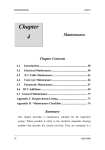
User’s Manual
English
T3 / T4 Conveyor
User´s Manual
This manual is intended for the inline device specified on the previous page. The manual contains
information to assist the operator to start and operate the device properly, and to maintain it.
Hardware and software mentioned in this document are subjected to continuous development and
improvement. Consequently, there may be minor discrepancies between the information in the document
and the performance and design of the hardware and software. Specifications, dimensions and other
statements mentioned in this document are subject to change without prior notice.
Conventions
In this manual angle brackets <> are used to indicate certain button or selector switch names.
Example: <Start> stands for the START button.
This manual comprises the following conveyor models
•
•
•
•
•
•
500mm
700mm
1000mm
1500mm
2000mm
2500mm
Manufacturer and its suppliers shall not be liable for any damages related to the software or hardware, or for any other damages whatsoever caused of the use of
or inability to use any manufacturer product. This is applicable even if manufacturer has been advised of the damage risk. Under any circumstances,
manufacturer’s entire liability shall be limited to replace such defective software or hardware which was originally purchased from
manufacturer.
Printed in Sweden.
mb702_061121u.doc/ 2006-12-11
1
User´s Manual
Contents
1.
SAFETY ................................................................................................................... 4
Warning sign .................................................................................................................. 5
Warnings......................................................................................................................... 5
2.
INSTALLATION ...................................................................................................... 6
Site preparation............................................................................................................... 6
Ambient conditions ........................................................................................................ 6
Technical data................................................................................................................. 6
Installation...................................................................................................................... 7
3.
PRODUCT DESCRIPTION....................................................................................... 8
Conveyor main parts ...................................................................................................... 8
Overview ......................................................................................................................... 9
General function............................................................................................................. 9
Control system.............................................................................................................. 11
4.
OPERATION SETUP .............................................................................................. 15
5.
MAINTENANCE.................................................................................................... 16
Weekly .......................................................................................................................... 16
Monthly ........................................................................................................................ 17
Yearly ............................................................................................................................ 17
Lubricant specifications ................................................................................................ 18
OKS 270 ........................................................................................................................ 18
6.
SERVICE ............................................................................................................... 19
Exchange of conveyor belt drive motor ....................................................................... 19
Exchange of conveyor belt rollers ................................................................................ 21
Exchange of conveyor belt ........................................................................................... 22
Setting of conveyor parallelism .................................................................................... 22
mb702_061121u.doc/ 2006-12-11
2
User´s Manual
Figures
Figure 1-1 Electric shock .................................................................................................... 5
Figure 1-2 Attention........................................................................................................... 5
Figure 3-1 Main parts ......................................................................................................... 8
Figure 3-2 Power switch ................................................................................................... 11
Figure 3-3 Hand unit buttons .......................................................................................... 11
Figure 3-4 Pack-length sensor .......................................................................................... 13
Figure 3-5 Speed control .................................................................................................. 13
Figure 6-2 Cover open...................................................................................................... 19
Figure 6-3 Motor & cables................................................................................................ 20
Figure 6-4 Drive wheel ..................................................................................................... 20
Figure 6-5 Belt roller ........................................................................................................ 21
Figure 6-6 Conveyor parallelism...................................................................................... 22
mb702_061121u.doc/ 2006-12-11
3
User´s Manual
1. Safety
Before starting the machine, it is necessary that the
operator, foreman and any other personnel involved in the
machine operation, maintenance or service understand and
obey the following:
•
Trained personnel must operate the machine only.
•
Anyone operating this machine must obey all warning
signs.
•
Do not use chemicals or other substances that may have
any influence on the operator or other personnel
involved in machine operation.
•
Apart from weekly, monthly and yearly maintenance
described in Chapter 5, Maintenance, the machine is to
be serviced by authorised personnel only.
•
All covers and shields must be intact, mounted and
closed while the machine is in operation.
•
Do not disable or disengage any safety switches or
sensors.
•
No hands or fingers are allowed in the vicinity of
moving parts of the machine.
mb702_061121u.doc/ 2006-12-11
4
User´s Manual
Warning sign
The warning sign on the machine must be observed as this
machine contains electrically live parts.
The warning sign on the machine is placed on the cover of
the electrical cabinet.
The sign must be kept clean and readable.
Figure 1-1 Electric shock
If the sign is missing, it must be replaced immediately.
The sign warns of electric shock. Units on which this sign is
placed contain dangerous voltage levels. Power supply must
be disconnected before opening the unit. Only authorised
service personnel are allowed to operate the machine when
the unit is open.
This sign is applied as follows.
• One sign on the cover of the electrical cabinet.
Warnings
Attention
Throughout the manual, this symbol is used to call your
attention to commands that starts machine movements. The
symbol refers to the warning signs, which must be obeyed to
eliminate the risk of injury. If there are instructions
accompanying this symbol, they must be followed.
Figure 1-2 Attention
mb702_061121u.doc/ 2006-12-11
5
User´s Manual
2. Installation
The machine is delivered fixed on a pallet.
Site preparation
Prior to installing the conveyor. Ensure that there is electric
power available on the site, see the requirements below.
Check also if the ambient conditions meet the requirements
specified below.
Ambient conditions
The ambient air must be clean.
Relative humidity
0 to 35°C
10 to 90 % noncondensing
35 to 60°C
10 to 60 % noncondensing
Allowed temperature
Operating:
5 to 40°C (41 to 104°F)
Storage:
-40 to 60°C (-40 to 140°F)
Dust and dirt
The machine does not require a clean-room environment
but the level of dust and dirt must be kept as low as possible.
The maintenance intervals are shortened by high
temperature and dusty or dirty environment.
Technical data
Machine
Weight:
Length:
Power supply
Voltage:
Frequency:
mb702_061121u.doc/ 2006-12-11
Depending on actual size.
See specification included in the
contract.
100-240 VAC
50/60 Hz
6
User´s Manual
Lifting information
The machine can be lifted with a forklift truck. Put some
wooden boards between the forks and the vertical frame
parts.
Installation
The installation must be carried out by authorised service
personnel.
Placing the unit
Ensure that the floor is sturdy. Place the machine on its site.
To be able to install, maintain and service the conveyor,
there must be a free space of one meter around it, except for
other devices and machines included in the conveyor line.
Levelling
Level the complete line carefully along the conveyor belts.
Use a spirit level across and along the conveyor belts when
adjusting the feet of the machine. The machine must stay
steady on all feet when the adjustment is finished.
Joining the units
The frameworks of the units to be joined are bolted together
with two plates and screws.
Mains supply
Mains supply is to be connected by an authorised electrician.
The transformer is auto adaptable to different primary
voltages. (100 to 240 VAC)
mb702_061121u.doc/ 2006-12-11
7
User´s Manual
3. Product description
This chapter describes the conveyor. The description is
divided into the following main sections:
•
Main parts of the conveyor.
•
Overview
•
General function of the conveyor.
•
Control system.
Conveyor main parts
C
A
B
E
F
D
G
H
Figure 3-1 Main parts
The following main parts are pointed out in the figure
above, by the letters.
Main parts
A.
B.
C.
D.
Safety cover.
Fixed rail. (Normally front rail)
Moving rail with sensors.
Cabinet 1, electrical cabinet with power supply and
control electronics.
E. Cabinet 2.
F. Power switch.
G. Smema connector.
H. Smema connector
mb702_061121u.doc/ 2006-12-11
8
User´s Manual
Overview
The conveyor (C) consists of a framework, an electrical
cabinet and two conveyor assemblies. It is equipped with
controls for width adjustment and optional functions such
as automatic width adjustment and board train. Also, a
board present sensor is positioned at the end of each belt
segment.
General function
Standard conveyor:
The conveyor transfers boards from one machine to
another. One PCB can be positioned on each belt segment
of the C at a time.
When the C is ready to receive a PCB from the preceding
unit, the C signals ”Ready” on the Smema In connector.
Board transfer from the preceding unit to the conveyor
starts, when the preceding unit signals ”Board Available”
(BA) and the C signals ”Ready” on the Smema In connector
at the same time.
When a PCB activates the board present sensor on the last
conveyor segment, the C signals ”BA” on the Smema Out
connector. If the subsequent machine signals ”Ready” while
the C signals ”BA” on Smema Out connector, the board is fed
out from the conveyor.
The C can be used as a manual loading conveyor, if boards
are placed anywhere on the conveyor activating a board
present sensor.
Packing conveyor (Board train):
The conveyor transfers boards, one by one, from the
preceding machine, and sends a pack (pcb-train) of boards
to the subsequent machine. One PCB can be positioned on
each belt segment of the C at a time, except on the last
conveyor segment where the pack is built.
When the C is ready to receive a PCB from the preceding
unit, the C signals ”Ready” on the Smema In connector.
Board transfer from the preceding unit to the conveyor
starts when the preceding unit signals ”Board Available”
(BA) and the C signals ”Ready” on the Smema In connector
at the same time.
When the board has passed the board present sensor on the
last but one conveyor segment, the last conveyor segment
immediately stops. When the pack of boards on the last
conveyor segment reaches the ‘Pack-length sensor’, the pack
mb702_061121u.doc/ 2006-12-11
9
User´s Manual
of boards is transported to the board present sensor located
at the end of the last segment, and the C signals ”BA” on
the Smema Out connector. If the subsequent machine signals
”Ready” while the C signals ”BA” on Smema Out connector,
the pack of boards is fed out from the conveyor.
The C can be used as a manual loading conveyor, if boards
are placed anywhere on the conveyor activating a board
present sensor.
Unpacking conveyor (Board train):
The conveyor receives and separates a pack (pcb-train) of
boards, and transfers boards, one by one, to the subsequent
machine. One PCB can be positioned on each belt segment
of the C at a time, except on the first segment where the
pack is received.
When the C is ready to receive a pack of boards from the
preceding machine, the C signals ”Ready” on the Smema In
connector.
Board transfer from the preceding unit to the conveyor
starts when the preceding unit signals ”Board Available”
(BA) and the C signals ”Ready” on the Smema In connector
at the same time.
When a pack is received at the first segment board present
sensor, the speed of the first segment is lowered, and
separation is achieved between the first and second
segment. When a PCB activates the board present sensor
located at the end of the last segment, the C signals ”BA” on
the Smema Out connector. If the subsequent machine signals
”Ready” while the C signals ”BA” on Smema Out connector,
the board is fed out from the conveyor.
The C can be used as a manual loading conveyor, if boards
are placed anywhere on the conveyor activating a board
present sensor.
mb702_061121u.doc/ 2006-12-11
10
User´s Manual
Control system
Power switch
Use the Power switch to turn the conveyor off or on.
0:
Conveyor off. All electrically controlled movements
are stopped and mains supply is disconnected.
1:
Conveyor on. (Production mode enabled.)
Figure 3-2 Power switch
Hand unit, manual width adjustment
Use the two upper buttons to manually adjust conveyor
width. Press and hold a button to run the width motor and
position the moving rail. The movement stops immediately
if the control switch is released or the conveyor is turned
off.
Figure 3-3 Hand unit buttons
mb702_061121u.doc/ 2006-12-11
11
User´s Manual
Hand unit, automatic width adjustment (option)
Use the button marked ‘AUTO’ to turn automatic width
adjustment off or on. An LED positioned above the button is
lit when the function is ON.
OFF:
Automatic width adjustment off.
Width information sent from previous machine is
ignored. Manual width adjustments are enabled.
ON:
Automatic width adjustment on.
Width is adjusted automatically based on width
information received from previous machine, or
based on width entered in the optional auto width
control unit (K-017-0488). The two width
adjustment buttons for manual width adjustments
are disabled.
Automatic width adjustment must always be set to ON when the
optional auto width control unit (K-017-0488) is connected to the
conveyor.
Hand unit, board train, start of line, end of line (option)
Use the button marked ‘BOARD TRAIN’ to turn the
packing/unpacking function off or on. An LED positioned
above the button is lit when the function is ON.
OFF:
Packing/unpacking function off. The conveyor
works as a standard conveyor.
ON:
Board train, start of line, or end of line function
on. The packing conveyor builds a pack (PCBtrain) of boards on the last conveyor segment. The
number of boards in the pack is determined by the
position of the ‘Pack-length sensor’ and board size.
The unpacking conveyor separates a pack of
boards from the first to second conveyor segment.
The start of line conveyor separates a pack of
boards on the last segment and the end of line
conveyor builds a pack of boards, starting at the
first or second conveyor segment.
Hand unit, inspection (option)
Use the button marked with an eye to turn inspection off or
on. An LED positioned above the button is lit when the
function is ON.
OFF:
Inspection off.
No PCBs are stopped for inspection.
ON:
Inspection on.
Each PCB is stopped for inspection.
To release the PCB when inspection is done, press
the button marked ‘OK’.
mb702_061121u.doc/ 2006-12-11
12
User´s Manual
Pack-length sensor, packing conveyor
The position of the pack-length sensor determines the
number of boards allowed in the pack (pcb-train). Loosen
the two screws and move the sensor to desired position.
Move the sensor towards the end of the conveyor to allow
more boards in the pack.
Figure 3-4 Pack-length sensor
Speed control, standard (option)
Speed control is used when it is necessary to adjust conveyor
transport speed to match the speed of the preceding or
subsequent machine. The speed control module is located
on the electrical plate. Turn the adjustment-knob clockwise
to increase conveyor speed, or counter-clockwise to
decrease. The standard speed control is applicable to the first
or last conveyor segment, and is active only during board
transfer from a preceding machine, or board transfer to a
subsequent machine.
The standard speed control does not reduce conveyor speed during
segment-to-segment board transfers (internal board transfers).
Figure 3-5 Speed control
mb702_061121u.doc/ 2006-12-11
13
User´s Manual
Speed control, packing conveyor
Speed control on the packing conveyor is used for building
the pack (pcb-train) on the last conveyor segment. The
speed of the last conveyor segment is reduced during
segment-to-segment board transfers, allowing boards to be
packed without leaving gaps.
See the document BoardTrain_051102u for instructions on
how to adjust speed.
This speed control is applicable only to the last conveyor
segment, and is active only during internal board transfers.
Speed is not reduced during board transfers from a preceding
machine, or to a subsequent machine.
Speed control, unpacking conveyor
Speed control on the unpacking conveyor is used for
separating a pack (pcb-train) of boards between the first and
second conveyor segment. The speed of the first conveyor
segment is reduced during segment-to-segment board
transfers, allowing the pack of boards to be separated into
single boards.
See the document BoardTrain_051102u for instructions on
how to adjust speed.
This speed control is applicable only to the first conveyor
segment, and is active only during internal board transfers.
Speed is not reduced during board transfers from a preceding
machine, or to a subsequent machine.
mb702_061121u.doc/ 2006-12-11
14
User´s Manual
4. Operation setup
1.
Connect smema cables and mains supply cable.
2.
Start the conveyor by switching the Power switch to ON
position.
3.
Set the width of the conveyor; see the section entitled
Control system in the preceding chapter. Slide the PCB
manually through the whole conveyor to test the
width. The PCB should slide smoothly without getting
stuck.
4.
The conveyor is now ready for production.
mb702_061121u.doc/ 2006-12-11
15
User´s Manual
5. Maintenance
The maintenance instructions in this chapter comprise
weekly, monthly and yearly maintenance for the conveyor.
The maintenance is very important for a continuous
operation without unintentional stops.
Follow the maintenance instructions carefully and keep the
conveyor clean.
Lubricants
Unless others are stated, use the OKS 270 grease.
Grease should be applied in small amounts, just to give a
thin film.
Specifications and part #’s for the lubricants are found in the
end of this chapter.
Weekly
Clean the machine.
Keep the conveyor clean all over.
Clean all sensors.
Wipe off dust and dirt from all sensors using a soft cotton
cloth. Clean the photo sensors at the end of each conveyor
segment. If the sensors are not clean, the conveyor will not
work properly.
All sensors are depicted in the document found in the
control cabinet at delivery.
mb702_061121u.doc/ 2006-12-11
16
User´s Manual
Monthly
Check the conveyor belt condition.
Check the conveyor belt condition and renew the belts if
required. Exchange of conveyor belt is described in the
chapter entitled Service.
Yearly
Guide ways for width adjustment.
Apply a small amount of lubricant, (OKS 270), to the entire
length, and both sides, of the guide ways. Adjust width to
both end positions after applying lubricant.
mb702_061121u.doc/ 2006-12-11
17
User´s Manual
Lubricant specifications
This section contains lubricant data for:
•
OKS 270 grease
OKS 270
OKS 270 is the base lubrication grease for the machine.
Data
Full product name: OKS 270
Type: Grease paste
Colour: Whitish
Flash point: >210°C
Supplier in Sweden
TriboTec AB
Box 203
S-435 24 Mölnlycke, Sweden
Phone: Nat. 031-88 78 80 Int. +46 31 78 80
www.tribotec.se
Manufacturer
OKS Spezialschmierstoffe GmbH
Triebstraße 9
D-80993 München
Phone: Nat. 089-14 98 920 Int. +49 89 14 98 920
www.oks-germany.com
mb702_061121u.doc/ 2006-12-11
18
User´s Manual
6. Service
This chapter contains the following service procedures:
•
•
•
•
Exchange of conveyor belt drive motor.
Exchange of conveyor belt rollers.
Exchange of conveyor belt.
Conveyor parallelism adjustment.
For other repair works, refer to the drawings and
information found in the control cabinet at delivery.
Exchange of conveyor belt drive motor
1.
Disconnect the power supply at the mains plug.
2.
Remove the aluminium cover plate by fitting a small
screwdriver to the hole near the end of the conveyor.
Use the screwdriver to bend the cover out and up. Then
push the cover straight forward and lift it off.
Figure 6-1 Opening cover
Figure 6-2 Cover open
mb702_061121u.doc/ 2006-12-11
19
User´s Manual
3.
Remove the drive belt from the drive wheel on the
motor that is to be exchanged.
4.
Remove the two cables from the drive motor, using a
soldering iron. Check the markings so you reconnect
them correctly.
Figure 6-3 Motor & cables
5.
Unscrew the four M3 screws that hold the drive motor,
and then pull out the drive motor and the belt drive
wheel. Remove the straps, which hold the cables to the
drive motor.
6.
Unscrew the setscrew that holds the belt drive wheel to
the drive shaft using a 1mm Allen key. Mount the belt
drive wheel on the new drive motor.
Figure 6-4 Drive wheel
7.
Mount the new drive motor with the M3 screws and
solder the cables back. Finally, replace the drive belt.
8.
Mount the aluminium cover plate.
mb702_061121u.doc/ 2006-12-11
20
User´s Manual
Exchange of conveyor belt rollers
1.
Turn the conveyor off, using the Power switch.
2.
Remove the aluminium cover plate by fitting a small
screwdriver to the hole near the end of the conveyor, as
shown in Figure 6-1. Use the screwdriver to bend the
cover out and up. Then push the cover straight forward
and lift it off.
3.
Remove the drive belt from the belt roller that is to be
exchanged.
4.
If the belt roller is located in the first section of the conveyor,
then unscrew the M6 nut using a 10mm monkey
wrench (BE adjustable spanner) and replace it with the
new belt roller but the old M6 nut and washer.
If the belt roller is located in the second or later section of the
conveyor, then remove the belt on the adjacent driver
motor. Unscrew the four screws holding the adjacent
driver motor and lift it aside without removing the
cables. Then remove the belt roller by unscrewing the
M6 nut and replace it with the new belt roller but the
old M6 nut and washer, using a 10mm monkey wrench.
Mount the driver motor.
Figure 6-5 Belt roller
5.
Fit the conveyor belt.
6.
Mount the aluminium cover.
7.
Turn the conveyor on, using the Power switch.
mb702_061121u.doc/ 2006-12-11
21
User´s Manual
Exchange of conveyor belt
1.
Turn the conveyor off, using the Power switch.
2.
Remove the conveyor belt by pulling it to the side.
3.
Fit the new belt by pushing it in place from the side.
4.
Turn the conveyor on, using the Power switch.
Setting of conveyor parallelism
1.
Turn the conveyor off, using the Power switch.
2.
Loosen all four M8 screws that hold the fixed conveyor
rail and adjust parallelism by slightly pushing the
conveyor profile in desired direction.
Figure 6-6 Conveyor parallelism
3.
Tighten the screws when parallelism is achieved.
4.
Turn the conveyor on, using the Power switch.
mb702_061121u.doc/ 2006-12-11
22