1
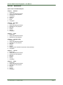
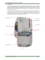
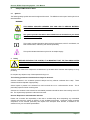
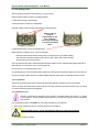
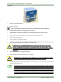
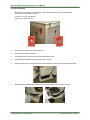
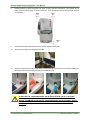
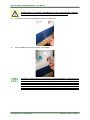
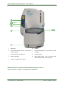
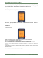
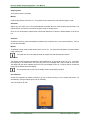
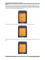
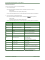
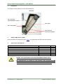
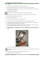
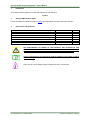
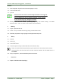
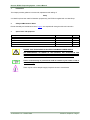
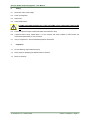
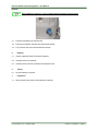
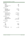
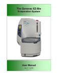
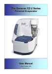
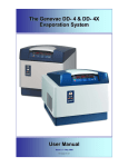
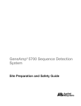
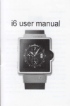
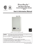
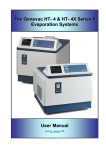
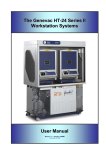
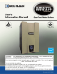
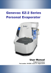
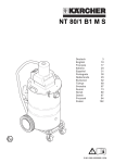
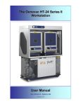
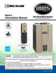
The Genevac EZ-Bio
Evaporation System
User Manual
Issue 1-3 – October 2008
Part Number 10-1610
General Information
This manual has been produced to assist in the daily running and routine maintenance of the Genevac
Evaporator.
Amendment Control Form
Only the effected pages and the Front Page will display the Revision Number all others will stay at initial issue.
Issue
Reason for Change
Date Issued
1
Only 1 Tip”n”Tell indicator now fitted to Packaging.
March 2005
2
Update to Solvent Group Guide – Section 1 Chapter 3 Page 1.
1-3
Update U.S. address
July 2005
24 Oct 2008
These instructions are subject to change without notice.
No part of these instructions may be reproduced in any form or be processed, duplicated or distributed by
electronic or optical means without the written permission of Genevac Limited.
All rights reserved. © Genevac Limited
These operating instructions should be read before you use the Genevac EZ-Bio Evaporating System.
Keep them near the system for easy reference.
Your attention is drawn in particular to Page (vi), Paragraph 3, Safety.
10-1610 Issue 1-3 – Octobeer 2008
CONTENTS
Amendment Control Form
1 Introduction
2 Safety and Maintenance Notes
WARNING
Caution
Note
Genevac Evaporators and Combustible Solvents
3
SAFETY
3.1 Safe loading of rotor
3.2 Lid operation
3.3 Limitations of use
SECTION 1
Chapter 1
GENERAL
UNPACKING AND SETTING UP
Flight Case.
Consumer Packaging
Chapter 2
QUICK START
Quick Start Guide
Error Warnings
Chapter 3
DETAILED OPERATION
SOLVENT LIMITATIONS
Evaporation of Acid Chlorides
Evaporation of Di-ethyl ether
Evaporation of High Boiling Point Solvents
Solvent Group Guide
Genevac and the ATEX Diective
Power Up
Starting a Run
Pre-cool Stage
Changing the Run
Setting Run Time
During a run
Pausing a Run
Stopping a Run
Shutdown
Out of Balance
Defrosting
Defrost Override
Draining
Lid Messages
Cleaning
SECTION 2
FAULT FINDING / DIAGNOSTICS
Safety Interlocks and Errors
Audible Warnings
Other Troubleshooting
User Vacuum Test
10-1610 Issue 1-3 – October 2008
Page i
Genevac EZ-Bio Evaporating System – User Manual
SECTION 3
MAINTENANCE
Spares and Consumables Request
Chapter 1 Software
1 Introduction
2 Safety and Maintenance Notes
3 Special tools and equipment
4 Preparation
5 Uploading
6 Testing
7 Errors
8 Completion
Chapter 2 Drive Belt
1 Introduction
2 Safety and Maintenance Notes
3 Special tools and equipment
4 Removal
5 Refitting
6 Testing
7 Completion
Chapter 3 Fuses
1 Introduction
2 Safety and Maintenance Notes
3 Special tools and equipment
Chapter 4 Lamp Assembly
1 Introduction
2 Safety and Maintenance Notes
3 Special tools and equipment
4 Removal
5 Refitting
6 Testing
7 Replacement of individual components of lamp assembly
8. Completion
Chapter 5 Lid Seal
1 Introduction
2 Safety and Maintenance Notes
3 Special tools and equipment
4 Removal
5 Refitting
6 Testing
7 Completion
Chapter 6 Pump
1 Introduction
2 Safety and Maintenance Notes
3 Special tools and equipment
4 Removal
5 Refitting
6 Testing
7 Completion
10-1610 Issue 1-3 – October 2008
Page ii
Genevac EZ-Bio Evaporating System – User Manual
Chapter 7 Pump Head Components
1 Introduction
2 Safety and Maintenance Notes
3 Special tools and equipment
4 Removal
5 Refitting
6 Testing
7 Completion
Chapter 8 Condenser Drain Valve Knob Assembly
1 Introduction
2 Safety and Maintenance Notes
3 Special tools and equipment
4 Removal
5 Refitting
6 Testing
7 Completion
SECTION 4 TECHNICAL SPECIFICATION
Mechanical Data
Vacuum system
Temperature controls
Condenser Data
Solvent compatibility
Dimensions
Power Supplies
Power Consumption
Environment
Operating
Storage
Emissions:
EC DECLARATION OF CONFORMITY
SAFETY
Warranty Statement
USEFUL INFORMATION
10-1610 Issue 1-3 – October 2008
Page iii
Genevac EZ-Bio Evaporating System – User Manual
1
Introduction
The product of detailed market research amongst biologists, the EZ-Bio is part of an integrated
development programme based on our highly successful EZ-2 solvent evaporation platform. The EZ-Bio
uses advanced and proven technology in evaporation science to solve the common problems of solvent
removal in Life Science. The new EZ-Bio Personal Evaporator is all a rugged and modern centrifugal
evaporator should be and more.
The EZ-Bio is suitable for low to medium boiling point solvents in the range up to 120°C. There are preprogrammed methods for DNA purification and extraction, oligosynthesis, protein purification and
removing aqueous mixtures. There is even a special method for HPLC fractions such as
Acetonitrile/water mixtures. Simple controls include temperature and time setting whilst a large, backlit
LCD display shows run status, time temperature and pressure.
COOLING VENTS
ACCESS CAP
DEFROST BUTTON
SIGHT GLASS
CONTROL PANEL
DRAIN TAP
LID
POWER SWITCH
Fig 1
10-1610 Issue 1-3 – October 2008
Page iv
Genevac EZ-Bio Evaporating System – User Manual
The use of the optional high-efficiency solvent resistant Teflon diaphragm pump, which is integral to the
evaporator, saves you space and provides quiet, efficient control of the vacuum. Combined with a new
visible glass condenser trap and easy access to solvent drain valve, the EZ-Bio is our most compact and
reliable sample evaporator yet.
Fig 2 - EZ-Bio Control Panel
Key elements in the design present real advantages for molecular biologists, protein and peptide
chemists as well as general-purpose solvent removal needs in life science laboratories:
•
•
•
•
Ultra compact design to save precious bench space
Easy to use with intuitive controls and large LCD display
Fast evaporation with full sample protection throughout
High throughput design
As well as being productive, the EZ-Bio is also highly versatile. It’s high capacity design accommodates a
wide selection of sample holders including:
•
•
•
•
•
100 x 0.5ml centrifuge tubes
64 x 1.5ml centrifuge tubes
4 shallow-well microplates
round-bottom flasks up to 500ml
tubes up to 160mm long and HPLC vials
10-1610 Issue 1-3 – October 2008
Page v
Genevac EZ-Bio Evaporating System – User Manual
2
2.1
Safety and Maintenance Notes
Symbols
The following safety symbols are used throughout this manual. The definitions and scope of each symbol is as
described below.
WARNING
THIS SYMBOL INDICATES HAZARDS THAT CAN LEAD TO SERIOUS MATERIAL
DAMAGE OR POTENTIAL SERIOUS INJURY.
Caution
This symbol provides information about hazards that can be harmful to your health
or lead to material damage.
Note
This symbol provides information about technical requirements, which if not followed, can
lead to malfunctions, inefficiency and reduced productivity.
This symbol indicates that there may be a risk to sample integrity.
3
Safety
BEFORE OPERATING THE SYSTEM, IT IS IMPORTANT THAT THE FOLLOWING NOTES
ARE READ TO ENSURE THAT THE IMPLICATIONS TO THE SAFETY OF PERSONNEL
OPERATING THE SYSTEM AND FOR THE PROTECTION OF SAMPLE INTEGRITY ARE
UNDERSTOOD.
Samples in the chamber are subjected to accelerations of up to 500G with a maximum load capacity of 1.5 kg
per swing.
Do not place any objects on top of the evaporator during a run
The following precautions should therefore always be observed:
Solvents condense in the condenser (external catchpot and any exhaust condenser when used).
solvents should be disposed of appropriately.
These
Solvent vapour is present in the exhaust line, this line should be run to a safe extraction source. This is
particularly important if acids are being used
Solvents can condense in the exhaust line and suitable precautions should be taken when working on the EZBio. This is particularly important if acids have been used.
Genevac Evaporators and Combustible Solvents
Please note it remains the responsibility of the user to consider safety when evaporating any combustible
solvents and ensure the system is placed in a well ventilated environment. Genevac's position regarding
evaporation of such solvents, particularly with respect to the European ATEX directive, is available on our
website or from your local sales representative.
10-1610 Issue 1-3 – October 2008
Page vi
Genevac EZ-Bio Evaporating System – User Manual
3.1 Safe loading of rotor
Never exceed the maximum load capacity of 1.5 kg per swing.
Balance sample holders to within 10g (approximately).
Locate tubes correctly in tube holders.
Load tube holders in balanced configurations.
Distribute tubes in sample holders symmetrically in both directions.
Genevac Ltd will
accept no
responsibility for any
loss or damage
incurred by improperly
or excessively loaded
rotors.
Locate sample blocks correctly in sample swings.
Before starting or restarting a run, check the following:
Ensure that both sample holders swing freely by swinging them by hand after loading.
The white PTFE washers located on each rotor pin are in place and in good condition.
All tube plates are correctly located.
Use only tubes that are able to withstand significant loads. Medium or thick wall Bora-Silica glass tubes with a
wall thickness of no less than 1.2mm are recommended.
Do not use worn or scratched tubes or vials.
Do not load tubes or vials into sample holders other than those types that have been approved by Genevac Ltd.
Do not use sample holders that have not been supplied with this system without consulting Genevac Service.
3.2 Lid operation
The lid has an electrical lock and is opened and closed manually after pressing the LID unlock button.
There is a safety device fitted that prevents the lid from being unlocked and opened whilst the rotor is rotating
or until the chamber pressure has equalised.
3.3 Limitations of use
Accuracy of IR Sensor is dependant upon condition of Sample Holders and Swings. To ensure
correct operation, Sample Holders and Swings are to be kept clean and free from contamination
and corrosion.
Your evaporating system is unsuitable for use under the following circumstances:
•
With strong mineral acids such as HCl and HBr at all concentrations.
EVAPORATING DIETHYL ETHER AND SIMILAR LOW AUTO-IGNITION SOLVENTS.
•
For use as a pressure vessel.
10-1610 Issue 1-3 – October 2008
Page vii
Genevac EZ-2 & EZ-2plus Evaporating System – Owners Manual
SECTION 1
GENERAL
Chapter 1
UNPACKING AND SETTING UP ...................................................................................................
Chapter 2
QUICK START ...............................................................................................................................
Chapter 3
DETAILED OPERATION ................................................................................................................
10-1610 Issue 1-3 – October 2008
Section 1
Genevac EZ-Bio Evaporating System – Owners Manual
Chapter 1
UNPACKING AND SETTING UP
10-1610 Issue 1-3 – October 2008
Section 1 Chapter 1 - Page 1
Genevac EZ-Bio Evaporating System – Owners Manual
Flight Case.
1.
Undo 4 quick release fasteners.
2.
Carefully remove lid.
Refer to photographs on Pages 2 to 4 inclusive of this Chapter for aditional guidance.
3.
Position base and EZ-Bio near to operating bench / location.
4.
With assistance (3 people total) lift EZ-Bio from base and position where required on bench.
5.
Ensure that there is 50mm clearance from edge of bench and other equipment.
6.
Refit lid and store flight case.
7.
Check contents of accessories container.
8.
Remove Condenser Drain Valve transportation blank (retain) and fit Drain Valve by carefully inserting into
condenser and screwing home (clockwise) until resistance is felt.
DO NOT USE THE CONDENSER DRAIN VALVE KNOB TO MOVE OR LIFT THE EZ-Bio.
FAILURE TO REMOVE BLANK AND FIT CONDENSER DRAIN VALVE KNOB WILL RESULT
IN THE EZ-Bio DISPLAYING ERROR “CLS Drn” AND PREVENTING THE RUN FROM
STARTING.
9.
Connect mains supply lead (supplied) to EZ-Bio.
10.
Connect suitable drain hose and container (not supplied).
DURING ITEM 11. THE EXHAUST HOSE MUST BE FITTED; THIS HOSE MUST THEN BE
DUCTED TO A SUITABLE EXTRACTION UNIT/AREA OR A FUME HOOD.
11.
Connect the long exhaust hose (supplied) and duct into fume hood. This is particularly important if HCl
or other acids are being used.
To maintain a solvent vapour free environment around your EZ-Bio, we suggest that you
do not use free space within the hood for storage of vessels containing solvents or
acids. Users should also ensure that tubing leading to and from the solvent condenser,
leads solvents and solvent vapours away from the machine in a safe manner. In
particular, the exhaust tube must be fitted to the outlet from the condenser and lead
away to the laboratory fume extraction system. This will ensure that any residual vapour
which passes through the condenser and pump does not cause damage to your system.
10-1610 Issue 1-3 – October 2008
Section 1 Chapter 1 - Page 1
Genevac EZ-Bio Evaporating System – User Manual
Consumer Packaging
1.
Before signing for package or before opening case, check that the tip’n’tell’s are not activated?
(If they are, contact Genevac service):
UK Service: +44 (0) 1473 243000
USA Service: (1) 845-267-2211
Not Activated
Activated
2.
Remove clips that retain the lid, and remove lid.
3.
Check contents against packing list.
4.
Remove the screws from the timber sleeve and carefully lift clear.
5.
Position base and EZ-Bio near to operating bench / location.
6.
With two people using 4 hand-holds lift and rotate evaporator to allow access to the back hand holds.
7.
With assistance (3 people total) lift EZ-Bio from base and position where required on bench.
10-1610 Issue 1-3 – October 2008
Section 1 Chapter 1 - Page 2
Genevac EZ-Bio Evaporating System – User Manual
8.
Ensure that there is 50mm clearance from edge of bench and other equipment. (The system can be
easily moved by placing paper or similar under feet. If this is employed, ensure all traces are removed
on completion.)
50mm
(2”)
50mm
(2”)
50mm
(2”)
9.
Remove accessories containers and check contents against packing note.
10.
Connect mains supply lead (supplied) to EZ-Bio.
11.
Remove Condenser Drain Valve transportation blank (retain) and fit Drain Valve by carefully inserting into
condenser and screwing home (clockwise) until resistance is felt.
DO NOT USE THE CONDENSER DRAIN VALVE KNOB TO MOVE OR LIFT THE EZ-Bio.
FAILURE TO REMOVE BLANK AND FIT CONDENSER DRAIN VALVE KNOB WILL RESULT
IN THE EZ-Bio DISPLAYING ERROR “CLS Drn” AND PREVENTING THE RUN FROM
STARTING.
10-1610 Issue 1-3 – October 2008
Section 1 Chapter 1 - Page 3
Genevac EZ-Bio Evaporating System – User Manual
DURING ITEM 14. THE EXHAUST HOSE MUST BE FITTED; THIS HOSE MUST THEN BE
DUCTED TO A SUITABLE EXTRACTION UNIT/AREA OR A FUME HOOD.
14.
Connect the long exhaust hose (supplied) and duct into fume hood.
15.
Connect suitable drain hose and container (not supplied).
To maintain a solvent vapour free environment around your EZ-Bio, we suggest that you
do not use free space within the hood for storage of vessels containing solvents or
acids. Users should also ensure that tubing leading to and from the solvent condenser,
leads solvents and solvent vapours away from the machine in a safe manner. In
particular, the exhaust tube must be fitted to the outlet from the condenser and lead
away to the laboratory fume extraction system. This will ensure that any residual vapour
which passes through the condenser and pump does not cause damage to your system.
10-1610 Issue 1-3 – October 2008
Section 1 Chapter 1 - Page 4
Genevac EZ-Bio Evaporating System – Owners Manual
Chapter 2
QUICK START
10-1610 Issue 1-3 – October 2008
Section 1
Genevac EZ-Bio Evaporating System – Owners Manual
7
8
2
9
3
4
5
6
1
1
Switch ON.
6
Close lid.
2
Press START button and wait for 90 second
safety countdown.
7
Set Max temperature as you would on a rotary
evaporator.
3
Press LID button when LED is lit.
8
Select RUN type.
4
Open lid after beep.
9
Press START button, your run will start using
default settings or last run time entered.
5
Load your samples in their holders.
Whilst the system is running the screen will indicate the progress of the run.
Please see Section 1 Chapter 3 of User Manual for more details.
10-1610 Issue 1-3 – October 2008
Section 1 Chapter 2 - Page 1
Genevac EZ-Bio Evaporating System – User Manual
ERROR WARNINGS
If an error occurs during a run then one of 2 things will happen:
1
The run will be terminated.
This means that the EZ-Bio has detected a failure in something that may have an effect on:
Sample Integrity
The physical condition of the evaporator
An error code will be displayed when the rotor has stopped spinning and the pressure is at atmosphere.
2
The run will continue in a reduced features mode.
This means that the EZ-Bio has detected a failure in something that does not have any effect on:
Sample Integrity
The physical condition of the evaporator
An error code will be displayed when the rotor has stopped spinning and the pressure is at atmosphere.
INDICATION
CLS Lid
CLS drn
PSH Strt
Err Lid
Err Loc
Err dru
Err bAL
Err UAC
Err 33 or
run SEL
dEF
OPn drn
OPn Lid
Err 06
CAUSE OF ERROR
Lid not closed (when run started)
Condenser drain open
Started with Lid or Drain open
Lid Closed indicating ‘Not Closed’
mid run
Lid Locked indicating Not Locked
mid run
Motor or Belt failure mid run
Out Of Balance Trip
Failure to pull a Vacuum or
Vacuum fails mid run
Rotary Run Selecter Switch in
incorrect position
Condenser requires defrosting
System needs draining
Lid Open activated
Tried to open lid before it is
unlocked
10-1610 Issue 1-3 – October 2008
RECTIFICATION
Ensure lid is closed.
Close condenser drain.
Push Start button
Operate lid “Unlock” button.
Open and re-close lid if required.
Operate lid “Unlock” button.
Open and re-close lid if required.
Stop run, remove samples and check drive/belt
Check samples balanced to within ≈10g
Check lid seal.
Refer to Section 2 of Owners Manual.
Ensure Rotary Run Selecter Switch is in correct
position.
Press Defrost button
1. Connect suitable drain tube.
2. Turn drain knob anti-clockwise (approx 4 turns).
Open Lid
Reset and try again, this time listen for solenoid
unlocking before lifting lid.
Section 1 Chapter 2 - Page 2
Genevac EZ-Bio Evaporating System – Owners Manual
Chapter 3
DETAILED OPERATION
10-1610 Issue 1-3 – October 2008
Section 1
Genevac EZ-Bio Evaporating System – Owners Manual
SOLVENT LIMITATIONS
Evaporation of Acid Chlorides
Do not attempt to evaporate this class of solvent in your system.
Evaporation of Di-ethyl ether
Do not attempt to evaporate this solvent in your system.
Evaporation of High Boiling Point Solvents
Genevac does not recommend the EZ-Bio for use with solvents whose boiling points at atmospheric pressure
are 170º C or above. This includes DMSO, DMI and NMP.
Solvent Group Guide
SOLVENT
Acetic acid
Acetonitrile
Ammonia
Dimethylamine
Chloroform
1,2 dichloroethane
Dichoromethane
1,4 Dioxane
Ethanol
Ethyl Acetate
Heptane
Hexane
Isopropanol
Methanol
Pyridine
Trifluoroacetic acid
Tetrahydrofuran
Toluene
Water
Water and Ammonia
Water and Acetonitrile
Water and Methanol
ABBREVIATION
HOAc, EtOOH
ACN, MeCN
NH3
DMA
TCE (Tri chloroethane)
DCE
DCM, methylene chloride
1,4 Diox
EtOH
EtAc, AcOEt
Hept
Hex
IPA
MeOH
Py
TFA
THF
PhMe
H2O
H2O + NH3
H2O + MeCN
H2O + MeOH
BEST PROGRAM TO USE
H2O
BP < 75
H2O + NH4OH
BP < 50
BP < 50
H2O
BP < 50
BP < 75
H2O
BP < 75
H2O
BP < 75
BP < 75 / H2O
BP < 75
H2O
MIXTURE BP < 75
BP < 50 / BP < 75
H2O
H2O
H2O + NH4OH
H2O + BP < 75
H2O + BP < 75
Note that where there are two programs listed, the first will give better solvent recovery, while the second may
give slightly faster drying.
Genevac and the ATEX Directive:
Please note that it remains the responsibility of the user to consider any solvents being evaporated within the
context of the ATEX directive. The presence of solvents on the list above indicates only that they will not
damage the system. If further information is required, please contact your Sales Representative or visit
http://www.genevac.com/
10-1610 Issue 1-3 – October 2008
Section 1 Chapter 3 - Page 1
Genevac EZ-Bio Evaporating System – User Manual
Power Up
The LCD (See Display) is made up of 110 segments and when the system is switched ON, it will illuminate for 1
second so that the you have time to observe that there are no segments missing. The display will then clear
and display “Sys Test” for a few seconds before displaying the software version (Version displayed may be
different to this image).
COUNTDOWN TIMER
Please note that the countdown timer counts down from 96 seconds, (Do not press the START
button until the countdown completed). This feature ensures that the EZ-Bio is in a safe mode for
continued operation. There could have been a power failure or power fluctuation in the lab that
caused the EZ-Bio to reset.
The condenser and pump will remain turned off until the Start key is pressed, at which point both are powered
up.
Starting a Run
The LCD display then becomes illuminated, showing pressure, temperature and an time remaining of 00:00.
See the paragraphs on Defrosting and Draining if the system prompts you, DEFROST BUTTON flashing.
Note that the lid will remain locked when there is no power to the system.
10-1610 Issue 1-3 – October 2008
Section 1 Chapter 3 - Page 2
Genevac EZ-Bio Evaporating System – User Manual
To open the lid press LID button – please wait the 3 seconds for the lid to release, then open the lid. The lid
remains unlocked for 10 seconds once the LCD indicates 'OPn Lid'.
Place your samples into the EZ-Bio.
Close the lid.
Select desired Solvent Type from rotary selector.
Select the required rotor temperature on the control knob.
Press START button.
When the start button is pressed the system will check that the lid is closed and locked and the drain
valve is closed then begin the run.
See the paragraph on Lid Messages to view displays.
In either case, a second press of the start button is then required to spin up the rotor and begin the
run. The display will prompt you with ‘PSH Strt’ while waiting.
If the run is not started within the 30 minutes of reaching the minimum chamber temperature required, then the
run will be cancelled.
10-1610 Issue 1-3 – October 2008
Section 1 Chapter 3 - Page 3
Genevac EZ-Bio Evaporating System – User Manual
Pre-cool Stage
Pre-cooling is automatically selected when required. If the chamber is not at, or sufficiently close to, the
required temperature when the start button is pressed then the system will enter pre-cool mode. Pre-cool is
sometimes required to avoid bumping of volatile solution.
If the system enters pre-cool mode with the lid closed then the rotor will spin up in ‘pulsed mode’.
The pre-cool temperature is determined by the run selected.
Changing the Run
You are able to change the run type at any time, even during a run. The system will automatically re-program
the system to the new settings. The new run is only accepted after a 3 second ‘thinking time’, incase you
change your mind and re-select the original run. Acceptance is confirmed by a short beep
TM
TM
The state of the Dri-Pure LED indicates if Dri-Pure is used in the run indicated but will not be illuminated
once the run is accepted (after the 3 second ‘thinking time’).
Max Sample temperature can be adjusted throughout the run and will be accepted immediately.
Irrespecitve of run selection, elapsed time will not be reset.
If the new run is a two-stage run and the time already elapsed is greater than the 1st stage time then the run
continues with the 2nd stage settings.
If the maximum allowable time for the new run is shorter than the time already elapsed, then the run will
terminate.
Setting Run Time
The maximum run time can be changed during a run should the need be to concentrate samples rather than
dry them. This can achieved in increments of 1 minute going up to hourly increments.
Press and hold the START button for 5 seconds, the pressure indication will change to display SEt, which will
flash rapidly. The Elapsed Time display will now indicate the proposed maximum run time.
By pressing the START button you can increase the time and by pressing the LID button you can decrease the
time.
Once you have set the required maximum run time, release the buttons. 5 seconds later the EZ-Bio display will
revert back to the current run status and the run will continue for the duration that you have just set.
All run duration changes are saved, so that the next time that you select the same run, the time that you
previously set will be used.
10-1610 Issue 1-3 – October 2008
Section 1 Chapter 3 - Page 4
Genevac EZ-Bio Evaporating System – User Manual
Another feature of the software is the ability to adjust the maximum run time further. If the previous procedure
has been used then you can also adjust the maximum run time by increments of 10 minutes by momentarily
pressing the START or LID buttons. If the maximum run time is 2 hours or less then you can only adjust the
time by 1 minute increments. This adjustment is not saved so will not affect future runs.
During a run
Time Remaining will be incrementing as the run progresses (HH:MM).
The Dri-PureTM LED indicator will be lit during any Dri-PureTM enabled run. During the Dri-PureTM part of a run,
the word Ramping will appear below Pressure on the LCD display.
Pausing a Run
Press the Pause button.
COUNTDOWN TIMER
System will vent and stop the rotor, coundown timer will count from 96 down to 0 (seconds).
The lid can then be opened and the samples examined.
The run can be re-started within the next 5 minutes (by closing the lid and pressing Start).
If Dri-PureTM had finished before the pause button was pressed, then Dri-PureTM will not be re-applied.
During the 5 minutes wait for a restart, the Time Remaining indicator will be counting down in MM:SS from
05:00 mins
Pause mode can be cancelled by pressing Stop while paused or by leaving the machine in pause mode for
longer than 5 minutes.
You can restart the run by pressing the PAUSE button again.
10-1610 Issue 1-3 – October 2008
Section 1 Chapter 3 - Page 5
Genevac EZ-Bio Evaporating System – User Manual
Stopping a Run
This can be manual or automatic:
Manual:
Press the Stop button while in the run. The system will vent and then the rotor will be brought to a halt.
Automatic:
Without any user input, the run will be automatically terminated when the Time Remaing reaches 00:00 The
system will then vent and the rotor will be brought to a halt, so ending the run.
Once the run has ended the system beeps 3 times and flashes the Lid button to attract attention to the end of
run
Shutdown
Shutdown is when the pump and backlight is shutdown (the condenser may or may not be shutdown). This can
be manual or automatic:
Manual:
To shutdown, simply press the Stop button (when not in a run). The pump will be purged for 30 minutes before
finally switching off.
The condenser will not be stopped unless the system has been defrosted and drained
Automatic:
The system will also shutdown automatically if left unattended for 15 minutes at the end of a run. This allows
the evaporator to be loaded at the end of the day safe in the knowledge that it will turn itself off when done.
The display will clear to the software version and the LCD backlight will turn off. The pump will turn off after the
purge time as defined above has elapsed.
The compressor will not switch off in standby mode if automatically turned off.
Out of Balance
Should the evaporator be loaded incorrectly or go out of balance during a run the system will end the run
automatically, venting and bringing the rotor to rest safely.
The LCD will show ‘Err bAL’.
10-1610 Issue 1-3 – October 2008
Section 1 Chapter 3 - Page 6
Genevac EZ-Bio Evaporating System – User Manual
Defrosting
If you switch ON and START the system without previously having DEFROSTED the system, you will be
prompted to DEFROST. The DEFROST button will flash rapidly to inform you that it is to be pressed and the
system defrosted before a run will be allowed to proceed.
The remaining defrost time is displayed on the screen.
Whenever the DEFROST button is illuminated, DEFROST can be cancelled.
Once DEFROST has been completed you will be promted to drain the condenser.
Defrost Override
When LCD displays 'dEF' and defrost button is rapidly flashing, simultaneously press and hold down the
DEFROST button and the STOP button for 10 secs.
DEFROST MUST NEVER BE CANCELLED OR OVERRIDEN IF THERE IS ANY DOUBT OVER
WHETHER OR NOT FROZEN SOLVENTS REMAIN IN THE CONDENSER.
Genevac recomends that you always defrost and drain before:
Switching off
Changing solvent types
System acknowledges the override with a beep and prompts you to drain as normal. (This cannot be
overridden)
10-1610 Issue 1-3 – October 2008
Section 1 Chapter 3 - Page 7
Genevac EZ-Bio Evaporating System – User Manual
Draining
Access to the tap for the drain valve is provided on the right hand side of the machine, towards the rear. It is a
multi-turn valve: turn counter-clockwise to open. The valve itself is made of glass/PTFE attached directly to the
bottom of the condenser and is at sufficient height to allow easy gravity draining into an appropriate receptacle.
The drain connection, located on the right-hand side of the machine, is fitted with a male thread to allow
connection of a drain tube via separate hose tail (supplied).
When the drain has been opened the LCD will display 'drn' and count down from 10 seconds.
If the drain valve is open when you try to start a run the LCD will display ‘CLS drn’ to prompt you to close the
drain.
10-1610 Issue 1-3 – October 2008
Section 1 Chapter 3 - Page 8
Genevac EZ-Bio Evaporating System – User Manual
Lid Messages
If the lid is not closed when the start button is pressed you will be told to close it with the message ‘CLS Lid’.
Cleaning - Condenser
Remove the cap from the top of the condenser.
Pour cleaning fluid into the condenser.
Clean using a bottlebrush.
Ensure suitable container is fitted to drain hose.
Open drain tap and allow cleaning fluid to drain into container.
Dispose of contaminated cleaning fluid in accordance with local regulations
10-1610 Issue 1-3 – October 2008
Section 1 Chapter 3 - Page 9
Genevac EZ-Bio Evaporating System – Owners Manual
SECTION 2
FAULT FINDING / DIAGNOSTICS
Safety Interlocks and Errors
Audible Warnings
User Vacuum test
Trouble shooting
10-1610 Issue 1-3 – October 2008
Section 2
Genevac EZ-Bio Evaporating System – Owners Manual
Safety Interlocks and Errors
If an error occurs during a run then one of 2 things will happen:
1
The run will be terminated.
This means that the EZ-Bio has detected a failure in something that may have an effect on:
Sample Integrity
The physical condition of the evaporator (Safety Critical)
An error code will be displayed when the rotor has stopped spinning and the pressure is at atmosphere.
2
The run will continue in a reduced features mode.
This means that the EZ-Bio has detected a failure in something that does not have any effect on:
Sample Integrity
The physical condition of the evaporator (Safety Critical)
An error code will be displayed when the rotor has stopped spinning and the pressure is at atmosphere.
INDICATION
AT START
CLS
Lid
CLS
drn
PSH
Strt
DURING RUN
Err
Lid
Err
Loc
Err
dru
Err
bAL
Err
UAC
MISCELLANEOUS
Err
33
run
SEL
OPn
drn
OPn
Lid
Err
06
CAUSE OF ERROR
RECTIFICATION
Lid not closed when run started
Ensure lid is closed
Drain left open
Close drain
Started with Lid or Drain open
Press START button
Lid Closed indicating ‘Not Closed’
mid run
Lid Locked indicating Not Locked
mid run
Motor or Belt failure mid run
Operate lid “Unlock” button.
Open and re-close lid if required.
Operate lid “Unlock” button.
Open and re-close lid if required.
Stop run, remove samples and check drive/belt
Out Of Balance Trip
Check samples balanced to within ≈10g
Failure to pull a Vacuum or
Vacuum fails mid run
Check lid seal.
Check drain valve.
Check condenser cap.
Check pump connections if disturbed.
Rotary Run Selector
incorrect position
Rotary Run Selector
incorrect position
System needs draining
Switch
in
Switch
in
Lid Unlock activated
Tried to open lid before it is unlocked
Ensure Rotary Run Selector Switch is in
correct position.
Ensure Rotary Run Selector Switch is in
correct position.
1. Connect suitable drain tube.
2. Turn drain knob anti-clockwise (approx 4
turns).
Open Lid
Reset and try again, this time listen for
solenoid unlocking before lifting lid.
Almost all error messages can be cancelled by holding the Stop button down for 5 seconds.
10-1610 Issue 1-3 – October 2008
Section 2 – Page 1
Genevac EZ-Bio Evaporating System – User Manual
Audible Warnings
Critical Error / User Warning
Shutdown Errors
Run finished
Key Acknowledge
Illegal key press
Audible warning format
Series of 10 long beeps as run ends
Repeats every 5 minutes until any user interaction (Button pressed,
Run select switch moved, Lid opened)
Three long beeps when system comes to rest
Repeats every 5 minutes until any user interaction (Button pressed,
Run select switch moved, Lid opened)
Short beep
Short double beep
Other Troubleshooting
SYMPTOM
Mains switch not illuminated
CAUSE
Supply failure
Fuse failure
LCD not operating
LCD not illuminated
Defrost prompt displayed (and defrost
button flashing)
Run does not appear to start
System in shutdown mode
System requires
defrosting
Chamber pre-cooling
Error has occurred
Rotor will not start to spin
No vacuum
Vacuum fails to pull down below
900mbar at start of a run
Vacuum pulls down to 500mbar but
rate slows dramatically
Vacuum pulls below 900mbar at start
of a run but takes longer than usual to
achieve a level of vacuum.
Vacuum stops pulling down at
215mbar, 115mbar and/or 30mbar.
Boiling of solvent in condenser
Lid will not open despite ‘OPn Lid’
displayed
10-1610 Issue 1-3 – October 2008
Drive belt failure
Drive motor fuse failure
Pump fuse failure
Pump failure
Lid not fully closed
Lid not sealing
DriPure
Drain valve seal or
condenser pot lid seal
damaged
Lamp glass cracked
ACTION
Check the system is switched on and
supply is available
Refer to maintenance section
As above
Press start button
Press defrost. Defrosting will start and
continue for a minimum of 40 mins
Pre-cool is indicated on the display.
The run will start when the system is
ready
Check display for information
messages and take appropriate action
(See previous table)
Refer to maintenance section
Refer to maintenance section
Refer to maintenance section
Refer to maintenance section
Stop run and check for obstructions
Stop run and check for obstructions, fit
and condition of lid seal. Replace if
required
The system is running correctly
Carry out user vacuum test to verify
problem.
Stop run and inspect/ replace lamp
glass assembly
Condenser full of volatile
Ensure condenser drained after every
solvent
run
Condenser fuse failed
Refer to maintenance section
Lamp glass seal damaged Carry out user vacuum test to verify
problem.
System waitng for
This is correct and no action is required.
condenser to cool.
It ensures maximum solvent recovery
and pump life.
No problem
This occurs normally
Drain valve not fully
Wind drain valve knob fully in
closed
Drain valve seal damaged If this affects the run then stop run and
inspect/ replace seal
Vent blocked
Remove blockage.
Lid seal stuck to glass
Allow the solvent to evaporate before
due to excessive solvent
further use.
on the lid seal.
Section 2 – Page 2
Genevac EZ-Bio Evaporating System – Owners Manual
Other Troubleshooting (Continued)
SYMPTOM
Lid is loose.
Runs take longer than expected
CAUSE
The lid is designed to
‘float’ on it’s hinges which
makes it feel loose.
Lamp failure
Vacuum leak
Incorrect run selected
Samples dry but not dry enough
Excessive quantity of solvent present
in catchpot / exhaust condenser
Or poor solvent recovery.
Low control temperature
set
Contamination of lamp
glass
Contamination of IR
sensor lens
Condenser fuse failure
Incorrect sample holder
for sample format
Various factors can cause
this
Incorrect run selected
Condenser full
Vacuum leak
Condenser fuse failed
Volatile solvent
Body of system gets hot
Excessive vibration
Excessive noise
Condensation inside chamber
Cannot unlock and open lid (lid LED
not lit)
This is acceptable under
normal operation
High out of balance
Incorrectly fitted pump
Incorrect run selected
Run changed after run
started
Spin down timer still
active
Lid button pressed too
often in 5 minutes
ACTION
This is correct an no action is required.
Check lamp is illuminated (by looking
through lid glass) and replace if failed.
Carry out user vacuum test
Check that the run selected is most
appropriate
Check that correct temperature is set
for the compound
Clean lamp glass
Clean IR sensor lens (Caution: refer to
maintenance section)
Refer maintenance section
Consult Genevac for advice
Consult Genevac for advice
Check that the run selected is most
appropriate
Ensure condenser drained after every
run
Verify by user vacuum test and check
causes above
Refer maintenance section
Some very volatile solvents will not be
trapped in the internal condenser –
use a Genevac external exhaust
condenser
Ensure balanced to avoid vibration.
Remove and refit pump
Check that the run selected is most
appropriate
Avoid doing this as the system will
have skipped the pre-heat
Wait until timer reaches zero then try
again
Wait for system to re-enable lid open
mechanism (LED will re light)
If action fails to resolve problem contact Genevac.
User Vacuum Test
1. Start defrost cycle (this will take a minimum of 40 minutes).
2. When any ice/frost is thawed inside the condenser pot, remove the cap and flush with volatile solvent
eg acetone (see Cleaning ).
3. Leave the cap off and the drain valve open during defrost.
4. On completion of the minimum defrost time (40 minutes) stop defrost, refit cap and close valve.
Start H2O run.
10-1610 Issue 1-3 – October 2008
Section 2 – Page 3
Genevac EZ-Bio Evaporating System – User Manual
SECTION 3
MAINTENANCE
Chapter 1
Software
Chapter 2
Drive Belt
Chapter 3
Fuses
Chapter 4
Lamp Assembly
Chapter 5
Lid Seal
Chapter 6
Pump
Chapter 7
Pump Head Components
Chapter 8
Condenser Drain Valve Knob Assembly
With the introduction of the EZ-Bio, Genevac is now offering it’s customers the ability to request spares and
consumables online.
The EZ-Bio is the first Genevac product to benefit from this new web-based feature.
To request your spares and consumables online click on the link below or copy and paste it into your browser.
http://www.genevac.com/contact/ezspares.html
10-1610 Issue 1-3 – October 2008
Section 3
Genevac EZ-Bio Evaporating System – Owners Manual
Chapter 1
Software
10-1610 Issue 1-3 – October 2008
Section 3
Genevac EZ-Bio Evaporating System – User Manual
1
Introduction
This chapter provides guidance in the updating of:
Software
Software Data Key
2
Safety and Maintenance Notes
Ensure that safety and maintenance notes, Page vi, are complied with throughout this work instruction.
3
Special tools and equipment
Description
Software Data Key
Part number
Dependant upon
Machine and Software
requirements
Quantity
1
ANY MAINTENANCE OR REPAIR OF THIS PRODUCT NOT DETAILED IN THIS
MANUAL SHALL BE CARRIED OUT BY GENEVAC PERSONNEL (OR APPROVED
REPRESENTATIVES OF GENEVAC) USING ONLY APPROVED SPARE PARTS.
OBSERVE PRECAUTIONS, ELECTROSTATIC SENSITIVE DEVICES.
10-1610 Issue 1-3 – October 2008
Section 3, Chapter 1 – Page 1
Genevac EZ-Bio Evaporating System – User Manual
4
Preparation
4.1
Ensure that evaporator is switched OFF.
4.2
Remove blanking cap from connector on evaporator.
4.3
Plug software “Data Key” into connector.
5
Uploading
5.1
Switch on evaporator.
5.2
The evaporator will automatically load software.
The existing code has to be deleted first. The display will show ‘ErS bLc n’ where n is the block
number. Each block could take up to 8 seconds and there are 4 blocks to erase. There will be no
progress indication during each block erase cycle. The block number will increment as each block
has been erased.
The software will then load code data from key, storing at the appropriate destination with the ‘Hour
Glass’ symbol animated in the top right hand corner of the LCD display. During upload, the system
displays ‘LoAd codE’ . This process can take up to 34 seconds so the time remaining target at the
lower right hand corner of the display will illuminate showing a percentage countdown, 99-0.
5.3
6
6.1
7
7.1
8
8.1
When the ‘’rSt SYS’ message is displayed:
5.3.1
Switch off.
5.3.2
Remove the software “Data Key”.
5.3.3
Refit blanking cap onto connector.
5.3.4
Switch back on (the new code is then used by the system).
Testing
No formal testing is required.
Errors
If any errors are observed and/or the evaporator fails to operate, make a note of the error code(s)
displayed and contact Genevac service.
Completion
Place software “Data Key” in a safe and secure place.
10-1610 Issue 1-3 – October 2008
Section 3, Chapter 1 – Page 2
Genevac EZ-Bio Evaporating System – Owners Manual
Chapter 2
Drive Belt
10-1610 Issue 1-3 – October 2008
Section 3
Genevac EZ-Bio Evaporating System – Owners Manual
1
Introduction
This chapter provides guidance in the removal and refitting of:
Drive Belt
BELT TENSION
MEASUREMENT POINTS
DRIVE BELT
BELT TENSIONER
DRIVE MOTOR
SECURING SCREWS
2
Safety and Maintenance Notes
Ensure that safety and maintenance notes, Page vi, are complied with throughout this work instruction.
3
Special tools and equipment
Description
DRIVE BELT
BELT TENSIONING TOOL
ALLEN KEY 6mm
Part number
04-2770
04-3658
Quantity
1
1
1
ENSURE THAT EVAPORATOR IS ISOLATED FROM MAINS POWER SUPPLY.
ANY MAINTENANCE OR REPAIR OF THIS PRODUCT NOT DETAILED IN THIS
MANUAL SHALL BE CARRIED OUT BY GENEVAC PERSONNEL (OR APPROVED
REPRESENTATIVES OF GENEVAC) USING ONLY APPROVED SPARE PARTS.
10-1610 Issue 1-3 – October 2008
Section 3, Chapter 2 – Page 1
Genevac EZ-Bio Evaporating System – User Manual
4
Removal
4.1
Remove ALL samples, sample holders and swings from evaporator.
4.2
Drain condenser and ensure that condenser access cap is secure and drain valve closed.
4.3
Ensure that the lid is closed and locked. Failure to do so could result in damage to the system when
placing evaporator on its back/side.
4.4
Disconnect mains power supply.
During item 4.5 place protective padding between evaporator and bench surface.
4.5
With assistance move evaporator to suitable bench and carefully lower evaporator onto its back.
4.6
Remove drive belt access panel securing screws.
4.7
Remove drive belt access panel.
4.8
Visually check condition of belt, ensure free from splits or tears.
4.9
If drive belt is intact and condition is acceptable check tension using special tool (04-3658).
4.10 Rotate the pulleys so that the tightest part of the belt is at the measurement point. This is done by feel
only. Mark this point on the belt using marker pen or chalk.
4.11 Place the supplied rubber band (nominally 160mm long, 1mm thick, 6mm wide max) over plain part of
pulleys. Ensure band is sitting flat and not on either the groove or the edge.
4.12 Slide the tensioning tool (tool) between the belt and the elastic band at a position along the belt
immediately adjacent to the tapped holes. Ensure min. gap between the tool shaft and the base of the
system.
4.13 Hold the tool such that a steady load can be applied to the rubber-covered end.
During item 4.14 the yellow end of the tool body should meet the mark of 3.5kg (Do not hold the body
of the tool).
4.14 Compress the tool so that the small spindle is just touching the elastic band.
4.15 If required, adjust tension as detailed in item 5.
10-1610 Issue 1-3 – January 2005
Section 3, Chapter 2 – Page 2
Genevac EZ-Bio Evaporating System – User Manual
4.16 If belt tension cannot be achieved replace belt as detailed in items 4.18 to 4.21 inclusive.
4.17 If belt is broken remove belt and check condition of drive pulleys.
4.18 Loosen the 4 drive motor securing screws (maximum 3 turns).
4.19 Loosen the lock-nut on the adjuster screw.
4.20 Rotate belt tension adjuster fully anticlockwise to loosen belt.
4.21 Remove belt.
5
Refitting
5.1
Ensure that the 4 drive motor securing screws are loosened.
5.2
Ensure that belt tensioner is fully unscrewed anticlockwise.
5.3
Position replacement belt over drive pulleys.
During item 5.4 check belt tension with special tool.
5.4
Screw in belt tension adjuster (clockwise) to tighten belt until correct tension is obtained.
5.5
Tighten the 4 drive motor securing screws.
5.6
Rotate belt one complete revolution.
5.7
Recheck belt tension and adjust accordingly.
5.8
Tighten lock-nut on adjuster screw against chassis.
5.9
Recheck belt tension and adjust accordingly.
6
6.1
7
Testing
Ensure that rotor rotates freely by hand.
Completion
7.1
Replace belt access panel.
7.2
Refit securing screws.
7.3
With assistance carefully stand the system back upright on it’s feet. Once upright it is acceptable to open
the lid again.
7.4
Reconnect mains power lead.
10-1610 Issue 1-3 – January 2005
Section 3, Chapter 2 – Page 3
Genevac EZ-Bio Evaporating System – Owners Manual
Chapter 3
Fuses
10-1610 Issue 1-3 – October 2008
Section 3
Genevac EZ-Bio Evaporating System – Owners Manual
1
Introduction
This chapter provides guidance in the removal, replacement and refitting of:
Fuses
2
Safety and Maintenance Notes
Ensure that safety and maintenance notes, Page vi, are complied with throughout this work instruction.
3
Special tools and equipment
Description
100 Volt – 50Hz System
F1= 5.0A
F2= 5.0A
F3= 8.0A
F4= 2.0A
F5= 10.0A
F6 Main Supply= 16.0A
F7 Main Supply= 16.0A
100 Volt – 60Hz System
F1= 5.0A
F2= 5.0A
F3= 8.0A
F4= 2.0A
F5= 10.0A
F6 Main Supply= 16.0A
F7 Main Supply= 16.0A
120 Volt System
F1= 4.0A
F2= 6.3A
F3= 8.0A
F4= 3.15A
F5= 10.0A
F6 Main Supply= 10.0A
F7 Main Supply= 10.0A
230/240 Volt System
F1= 4.0A
F2= 3.15A
F3= 4.0A
F4= 2.0A
F5= 5.0A
F6 Main Supply= 6.3A
F7 Main Supply= 6.3A
Part number
Quantity
04-3595
04-3595
04-3592
04-3594
04-3593
04-3766
04-3766
1
1
1
1
1
1
1
04-3595
04-3595
04-3592
04-3594
04-3593
04-3766
04-3766
1
1
1
1
1
1
1
04-3589
04-3590
04-3592
04-3591
04-3593
04-3588
04-3588
1
1
1
1
1
1
1
04-3589
04-3591
04-3589
04-3594
04-3595
04-3587
04-3587
1
1
1
1
1
1
1
ENSURE THAT EVAPORATOR IS ISOLATED FROM MAINS POWER SUPPLY.
ANY MAINTENANCE OR REPAIR OF THIS PRODUCT NOT DETAILED IN THIS
MANUAL SHALL BE CARRIED OUT BY GENEVAC PERSONNEL (OR APPROVED
REPRESENTATIVES OF GENEVAC) USING ONLY APPROVED SPARE PARTS.
10-1610 Issue 1-3 – October 2008
Section 3, Chapter 3 – Page 1
Genevac EZ-Bio Evaporating System – User Manual
The 2 mains supply fuse holders F6 and F7 are standard screw type located next to the mains power connector
on the left hand side of the evaporator (viewed from the front).
Fuse holders F1, F2, F3, F4 and F5 are quick release, bayonet type, and are located on the back panel (left
hand corner viewed from the front) of the evaporator.
If a fuse blows more than once, please contact Genevac Service Department. To ensure uninterrupted service
always ensure a spare fuse is available.
10-1610 Issue 1-3 – October 2008
Section 3, Chapter 3 – Page 2
Genevac EZ-Bio Evaporating System – Owners Manual
Chapter 4
Lamp Assembly
10-1610 Issue 1-3 – October 2008
Section 3
Genevac EZ-Bio Evaporating System – Owners Manual
1
Introduction
This chapter provides guidance in the removal, replacement and refitting of:
Lamp Assembly
2
Safety and Maintenance Notes
Ensure that safety and maintenance notes, Page vi, are complied with throughout this work instruction.
3
Special tools and equipment
Description
LAMP ASSEMBLY - STANDARD
Part number
70-0497/S
Quantity
1
Lamp assembly individual components:
LENS - STANDARD
LAMP
‘O’ RING
04-2948
AC9060
04-3369
1
1
1
ALLEN KEY 2.5mm
ALLEN KEY 4mm
04-1125
AB9603
1
1
ENSURE THAT EVAPORATOR IS ISOLATED FROM MAINS POWER SUPPLY.
ANY MAINTENANCE OR REPAIR OF THIS PRODUCT NOT DETAILED IN THIS
MANUAL SHALL BE CARRIED OUT BY GENEVAC PERSONNEL (OR APPROVED
REPRESENTATIVES OF GENEVAC) USING ONLY APPROVED SPARE PARTS.
Traces of solvents may be present that could be harmful to your health or lead to
material damage.
There may be a risk to sample integrity if lamp fails to operate or required vacuum is not
achieved.
10-1610 Issue 1-3 – October 2008
Section 3, Chapter 4 – Page 1
Genevac EZ-Bio Evaporating System – User Manual
Removal
4.1
Open lid.
LAMP ASSEMBLY MAY BE HOT!
4.2
Allow lamp to cool if system used recently.
4.3
Disconnect mains power supply.
During item 4.4 note locations of screws as they are of different lengths
4.4
Using allen key remove screws (qty 2, long screw to the front) from lamp access panel (located on the
right hand side, viewed from the front).
4.5
Remove panel.
4.6
Disconnect lamp power lead bulkhead connector (by unscrewing collar, suggest using left hand).
4.7
Loosen and remove thumb screw.
THUMB SCREW
CONNECTOR
4.8
Carefully withdraw lamp assembly.
10-1610 Issue 1-3 – October 2008
Section 3, Chapter 4 – Page 2
Genevac EZ-Bio Evaporating System – User Manual
5
Refitting
5.1
Unpack replacement lamp assembly and retain packaging.
LAMP/CHAMBER SEAL
BULKHEAD CONNECTOR
COLLAR
5.2
Check that lamp/chamber seal is located correctly.
5.3
Locate lamp assembly bracket into guide.
5.4
Offer up to chamber and ensure assembly locates securely.
5.5
Fit and tighten thumb screw.
5.6
Connect lamp power lead to bulkhead connector.
5.7
Ensure collar is rotated clockwise ¼ turn.
5.8
Refit access panel and secure with screws (qty 2, long screw to the front), in locations noted at item 4.4.
DO NOT USE SYSTEM WITHOUT PANEL BEING FITTED!
5.9
6
Reconnect Mains power supply.
Testing
6.1
Select H2O.
6.2
Set temperature to 60ºC
6.3
Press START button.
6.4
Ensure that pressure drops to below 500 mbar and continues to drop.
If pressure fails to drop, check that lamp seal is correctly located on chamber wall and repeat items
6.1 to 6.4 inclusive.
6.5
Carry out required run, ensure that desired pressure is achieved.
6.6
Check that lamp illuminates.
10-1610 Issue 1-3 – October 2008
Section 3, Chapter 4 – Page 3
Genevac EZ-Bio Evaporating System – User Manual
7
Replacement of individual components of lamp assembly
It is acceptable to replace the glass, ‘O’ rings &/or lamp individually by dismantling the lamp
assembly:
7.1
Remove the lamp assembly as in items 4.1 to 4.7 above.
7.2
Unscrew 4 off pozi-drive screws retaining the bracket.
7.3
Remove the lamp by pulling firmly from the ceramic holder.
7.4
Remove the glass and ‘O’ ring.
7.5
Fit new ‘O’ ring on both sides of lamp ring.
During item 7.6 ensure that the Red Robax lens is correctly orientated
7.6
Fit new glass (ensure glass is clean).
7.7
Replace bracket with new lamp (if required).
7.8
Refit 4 off pozi-drive screws with spring washers and tighten hard.
7.9
Refit assembly as in item 5 above.
7.10 Test assembly as in item 6 above.
Completion
8.1
Place defective lamp assembly into packaging for despatch back to Genevac.
8.2
Return to Genevac.
10-1610 Issue 1-3 – October 2008
Section 3, Chapter 4 – Page 4
Genevac EZ-Bio Evaporating System – Owners Manual
Chapter 5
Lid Seal
10-1610 Issue 1-3 – October 2008
Section 3
Genevac EZ-Bio Evaporating System – Owners Manual
1
Introduction
This chapter provides guidance in the removal, replacement and refitting of:
Lid Seal
2
Safety and Maintenance Notes
Ensure that safety and maintenance notes, Page vi, are complied with throughout this work instruction.
3
Special tools and equipment
Description
LID SEAL
Part number
70-0603/S
Quantity
1
ANY MAINTENANCE OR REPAIR OF THIS PRODUCT NOT DETAILED IN THIS
MANUAL SHALL BE CARRIED OUT BY GENEVAC PERSONNEL (OR APPROVED
REPRESENTATIVES OF GENEVAC) USING ONLY APPROVED SPARE PARTS.
Traces of solvents may be present that could be harmful to your health or lead to
material damage.
There may be a risk to sample integrity if required vacuum is not achieved.
10-1610 Issue 1-3 – October 2008
Section 3, Chapter 5 – Page 1
Genevac EZ-Bio Evaporating System – User Manual
Removal
4.1
Swich evaporator ON (wait for 95 seconds as displayed on LCD).
4.2
Press LID OPEN button.
4.3
Open lid.
Check for traces of solvent on seal and wipe clean before removing seal.
The seal material may absorb significant quantities of some solvents.
Do not use tools, they may damage the chamber
4.4
5
Manually remove seal from chamber by carefully pulling away from chamber working on a 200mm
section at a time. Once one comes out the remainder is removed easily.
Refitting
5.1
Unpack replacement lid seal.
5.2
Position on top of chamber wall with ‘lip’ pointing inwards towards centre.
5.3
Work firmly into position using only fingers, ensuring the seal is fully home.
6
Testing
6.1
Close lid.
6.2
Select H2O.
6.3
Press START button.
6.4
Ensure that pressure drops to below 500 mbar and continues to drop.
When a new seal is fitted manual pressure may be required on the lid to assist to bed in the seal.
If pressure fails to drop, check that seal is correctly located on chamber wall and repeat items 6.1 to
6.4 inclusive.
6.5
7
7.1
Carry out required run, ensure that desired pressure is achieved.
Completion
Dispose of defective seal and packaging.
10-1610 Issue 1-3 – October 2008
Section 3, Chapter 5 – Page 2
Genevac EZ-Bio Evaporating System – Owners Manual
Chapter 6
Pump
10-1610 Issue 1-3 – October 2008
Section 3
Genevac EZ-Bio Evaporating System – Owners Manual
1
Introduction
This chapter provides guidance in the removal, replacement and refitting of:
Pump
A 4 Head Pump has been used for illustration purposes only, the EZ-Bio is supplied with a 2 Head Pump.
2
Safety and Maintenance Notes
Ensure that safety and maintenance notes, Page vi, are complied with throughout this work instruction.
3
Special tools and equipment
Description
Pump 2 head 100/120 Volt
Pump 2 head 230 Volt
Part number
70-0516/S
70-0517/S
Quantity
AR
AR
ENSURE THAT EVAPORATOR IS ISOLATED FROM MAINS POWER SUPPLY.
ANY MAINTENANCE OR REPAIR OF THIS PRODUCT NOT DETAILED IN THIS
MANUAL SHALL BE CARRIED OUT BY GENEVAC PERSONNEL (OR APPROVED
REPRESENTATIVES OF GENEVAC) USING ONLY APPROVED SPARE PARTS.
Traces of solvents may be present that could be harmful to your health or lead to
material damage.
There may be a risk to sample integrity if required vacuum is not achieved.
10-1610 Issue 1-3 – October 2008
Section 3, Chapter 6 – Page 1
Genevac EZ-Bio Evaporating System – User Manual
Removal
4.1
Disconect mains power supply.
4.2
From rear of evaporator undo the ¼ turn fasteners (qty 4) that secure pump tray assembly.
Do not subject the PTFE hoses and cables to undue strain.
4.3
Carefully withdraw pump tray assembly.
FASTENERS
POWER CONNECTOR
Fig 1 – 4 Head Pump
4.4
Disconnect pump power connector.
During item 4.5 the PTFE hoses are left connected to the pump.
4.5
5
Carefully note position of the 2 PTFE hoses and disconnect from evaporator.
Refitting
5.1
Unpack replacement pump and retain packaging.
5.2
Remove blanking caps from the two hoses and retain.
5.3
Position pump assembly and connect PTFE hoses to positions noted at item 4.5.
5.4
Connect pump power connector.
During item 5.5 ensure that the PTFE hoses and cables are not trapped or distorted.
5.5
Carefully slide pump assembly into back of evaporator.
5.6
Secure with the fasteners (qty 4).
10-1610 Issue 1-3 – October 2008
Section 3, Chapter 6 – Page 2
Genevac EZ-Bio Evaporating System – User Manual
6
Testing
6.1
Reconnect mains power supply.
6.2
Power up evaporator.
6.3
Select H2O.
6.4
Press START button.
IF PUMP LINES ARE INCORRECTLY FITTED THE PUMP COULD PRESSURISE THE SYSTEM
CAUSING DAMAGE: TURN SYSTEM OFF IF PRESSURE INCREASE OCCURS DURING ITEM
6.5
6.5
Ensure that pressure drops to below 500 mbar and continues to drop.
6.6
If pressure fails to drop, repeat items 4.1 to 4.3 inclusive and check condition of PTFE hoses and
connections repeat items 6.1 to 6.5 inclusive.
6.7
Carry out required run, ensure that desired pressure is achieved.
7
Completion
7.1
Fit hose blanking caps to defective pump.
7.2
Place pump into packaging for despatch back to Genevac.
7.3
Return to Genevac.
10-1610 Issue 1-3 – October 2008
Section 3, Chapter 6 – Page 3
Genevac EZ-Bio Evaporating System – Owners Manual
Chapter 7
Pump Head Components
10-1610 Issue 1-3 – October 2008
Section 3
Genevac EZ-Bio Evaporating System – Owners Manual
1
Introduction
This chapter provides guidance in the removal, replacement and refitting of:
Pump Head Components
2
Safety and Maintenance Notes
Ensure that safety and maintenance notes, Page vi, are complied with throughout this work instruction.
3
Special tools and equipment
Description
2 Head - Pump Head Service Kit
Pulley Spanner 44/3 3mm
Allen Key 4mm
Spanner Open Ended 17mm
Part number
04-3715
AC2370
AB9603
Quantity
AR
1
1
1
ENSURE THAT EVAPORATOR IS ISOLATED FROM MAINS POWER SUPPLY.
ANY MAINTENANCE OR REPAIR OF THIS PRODUCT NOT DETAILED IN THIS
MANUAL SHALL BE CARRIED OUT BY GENEVAC PERSONNEL (OR APPROVED
REPRESENTATIVES OF GENEVAC) USING ONLY APPROVED SPARE PARTS.
Traces of solvents may be present that could be harmful to your health or lead to
material damage.
There may be a risk to sample integrity if required vacuum is not achieved.
10-1610 Issue 1-3 – October 2008
Section 3, Chapter 7 – Page 1
Genevac EZ-Bio Evaporating System – User Manual
Removal
PUMP HEAD
ASSEMBLY
Fig 1
4.1
Remove pump as detailed in Chapter 6. and place on suitable work surface.
4.2
Remove punp from tray by removing attachment screws.
4.3
Note and mark position of PTFE tubes.
4.4
Disconnect the 2 PTFE tubes from the connectors on the pump head.
4.5
Using Allen Key, remove the 4 retaining screws from the pump head.
Fig 2
4.6
Remove pressure plate.
4.7
Carefully remove the connecting head.
4.8
Carefully remove valves (qty 2) and “O” ring seals (qty 2).
Fig 3
4.9
Carefully remove pump head.
10-1610 Issue 1-3 – October 2008
Section 3, Chapter 7 – Page 2
Genevac EZ-Bio Evaporating System – User Manual
4.10 Using Pulley Spanner, carefully locate in Strain Washer and rotate anticlockwise.
Fig 4
4.11 Remove Strain Washer, Diaphragm and Pressure Disc assembly.
PRESSURE PLATE
CONNECTING HEAD
“O” RING
SEALS &
VALVES
PUMP
HEAD
PRESSURE
DISC
DIAPHRAGM
STRAIN
WASHER
Fig 5
4.12 Separate the three items
10-1610 Issue 1-3 – October 2008
Section 3, Chapter 7 – Page 3
Genevac EZ-Bio Evaporating System – User Manual
5
Refitting
5.1
Remove replacement components from service kit packaging.
5.2
Ensure that all items are correct (Fig 5).
Do not use any assembly oils or fluids when reassembling the pump. Clean distilled water
may be used to locate seals and valves during assembly.
5.3
Assemble Strain Washer, Diaghragm and Pressure Disc (Fig 5).
5.4
Carefully locate onto pump connecting rod.
Fig 6
5.5
Using Pulley Spanner, carefully locate in Strain Washer and rotate clockwise (Fig 4).
5.6
Carefully refit pump head.
5.7
Carefully fit valves (qty 2) into pump head (Fig 3).
5.8
Carefully fit “O” ring seals (qty 2) into pump connecting head (Fig 3).
5.9
Carefully fit pump connecting head.
5.10 Refit pressure plate.
5.11 Refit securing screws (qty 4).
5.12 Reconnect the 2 PTFE tubes to the pump head connections.
5.13 Refit pump tray and secure with attachment screws
5.14 Refit pump as detailed in Chapter 6.
6
6.1
7
7.1
Testing
Test as detailed in Chapter 6.
Completion
Safely discard old seals and valves.
10-1610 Issue 1-3 – October 2008
Section 3, Chapter 7 – Page 4
Genevac EZ-Bio Evaporating System – Owners Manual
Chapter 8
Condenser Drain Valve
Knob Assembly
10-1610 Issue 1-3 – October 2008
Section 3
Genevac EZ-Bio Evaporating System – Owners Manual
1
Introduction
This chapter provides guidance in the removal, replacement and refitting of:
Condenser Drain Valve Knob Assembly
2
Safety and Maintenance Notes
Ensure that safety and maintenance notes, Page vi, are complied with throughout this work instruction.
3
Special tools and equipment
Description
Drain Valve Knob Assembly
Part number
70-0617/S
Quantity
1
ENSURE THAT EVAPORATOR IS ISOLATED FROM MAINS POWER SUPPLY.
ANY MAINTENANCE OR REPAIR OF THIS PRODUCT NOT DETAILED IN THIS
MANUAL SHALL BE CARRIED OUT BY GENEVAC PERSONNEL (OR APPROVED
REPRESENTATIVES OF GENEVAC) USING ONLY APPROVED SPARE PARTS.
Traces of solvents may be present that could be harmful to your health or lead to
material damage.
There may be a risk to sample integrity required vacuum is not achieved.
10-1610 Issue 1-3 – October 2008
Section 3, Chapter 8 – Page 1
Genevac EZ-Bio Evaporating System – User Manual
Removal
Do not attempt to replace ‘O’ rings as high performance elastic has been used.
4.1
Ensure that evaporator is switched OFF.
4.2
Ensure that condenser has been fully drained and flushed.
4.3
Fully unscrew drain valve anticlockwise and remove.
5
Refitting
5.1
Unpack replacement Drain Valve Knob Assembly.
5.2
Carefully insert into condenser.
5.3
Carefully screw valve fully clockwise until resistance is felt.
6
6.1
7
7.1
Testing
No formal testing is required.
Completion
Return suspect Drain Valve Knob Assembly to Genevac.
10-1610 Issue 1-3 – October 2008
Section 3, Chapter 8 – Page 2
Genevac EZ-Bio Evaporating System – Owners Manual
SECTION 4
TECHNICAL SPECIFICATION
10-1610 Issue 1-3 – Octobber 2008
Section 4
Genevac EZ-Bio Evaporating System – Owners Manual
Mechanical Data
Max RPM
Max G
Drive system
Sample load including swings
Max. imbalance
IR lamps number
2000
500 G
Direct
1.5 kg
40g
1
Vacuum system
Pressure display
Automatic Pressure control
Bump protection
System ultimate pressure
Auto vacuum vent valve
0-1200 mbar
10 mbar -atm
Yes
10 mbar
Yes
Temperature controls
Ambient to 80° C
+/- 2.5° C
infra red pyrometer
-99 to + 99° C
Ambient
Temperature control range
Temperature control accuracy
Temperature sensing
Temperature display range
Chamber / lid temp. range
Condenser Data
Condenser temperature
Vacuum pots (number)
Useable Capacity - vacuum pot
Materials – condenser pots
Drain valve
-40° C
1
1 litre
Borosilicate glass
Glass / PTFE / Isolast
Solvent compatibility
Up to 130° C
Boiling points
Dimensions
Width
Depth
Height
Weight
540 mm
650 mm
687 mm
84.5kg
Power Supplies
120V (±10%)
230V (±10%)
60Hz
50Hz
10-1610 Issue 1-3 – October 2008
15A
13A
(USA)
(UK + Europe)
Section 4 – Page 1
Genevac EZ-Bio Evaporating System – User Manual
Power Consumption
Peak:
230V 50Hz
120V 60Hz
1610VA
1800VA
Note: The systems may momentarily take current in excess of the figures quoted above. Genevac
therefore recommends the use of appropriately rated type D circuit breakers on the main supply to
the EZ-Bio.
Environment
The following figures apply:
Operating
Ambient Temperature:
Relative Humidity:
Altitude:
15°C to 30°C
10 – 60%
Sea Level to 1,600m
Storage
Ambient Temperature:
Relative Humidity:
Altitude:
-10°C to 60°C
10 – 80%
Sea Level to 12,000m
Emissions:
Noise levels do not exceed 55dBA at one metre from the evaporator.
10-1610 Issue 1-3 – October 2008
Section 4 – Page 2
Genevac EZ-Bio Evaporating System – User Manual
EC Declaration of Conformity
We Genevac Limited
Declare that this product:
EZ-Bio Evaporating System
Complies with the relevant Essential Health and
Safety Requirements of the European Machinery
Directive (89/392/EEC as amended by 91/368 EEC
and 93/44/EEC). The EMC Directive 89/336/EEC
and the Low voltage Directive 73/23/EEC.
Conformity is demonstrated by compliance with the
following specifications:EN 60204-1:1998, Safety of machinery– Electrical
equipment of machines-Pt 1 General Requirements
EN 249: 1992, Safety of machinery– Safety
distances to prevent danger zones being reached by
upper limbs.
THIS EVAPORATOR HAS BEEN DESIGNED TO
BE USED IN A POLLUTION DEGREE 1
ENVIRONMENT (NO POLLUTION, OR ONLY DRY
NON-CONDUCTIVE POLLUTION).
ANY MAINTENANCE OR REPAIR OF THIS
PRODUCT NOT DETAILED IN THIS MANUAL
SHALL BE CARRIED OUT BY GENEVAC
PERSONNEL
(OR
APPROVED
REPRESENTATIVES OF GENEVAC) USING ONLY
APPROVED SPARE PARTS
Warranty Statement
This product is guaranteed for period of 12 months
from the date of delivery to site. In the unlikely event
of any defect arising due to faulty materials or
construction resulting in system failure, the unit will
be repaired free of charge. This to include all labour
and component costs incurred.
This warranty is subject to the following provisions:
1.
System to be returned to Genevac
appropriate packaging* for repair.
2.
System must be sited, installed and operated in
accordance with operator instruction manual.
BS EN ISO 12100 pts 1 & 2:2003, Safety of
Machinery - Basic concepts, general principles for
design.
3.
All vapours must be ducted away from the
system as described in the installation
instructions and operator manual
BS
EN
50082-1:
1998,
Electromagnetic
compatibility-Generic immunity standard.
4.
Unit only used for purpose it was sold, and in
accordance with Genevac published solvent list.
5.
Preventative maintenance to be adhered to as
detailed in operator’s manual.
6.
Consumable** items to be replaced as and
when necessary by operator. Only Genevac
approved parts to be used.
7.
Vacuum pump to be exchanged for refurbished
unit in event of failure. Owner responsible for
exchange and return of failed unit.
8.
Warranty does not cover accidental damage,
misuse or inappropriate repair by untrained
personnel.
EN 1088: 1996, Safety of machinery. Interlocking
devices associated with guards. Principles of design
and selection.
BS EN 61010-2-020: 1995, Safety requirements for
electrical equipment for measurement, control and
laboratory use. Particular requirements for laboratory
centrifuges.
Safety
WARNING!
THIS SYSTEM MUST BE EARTHED
THIS EVAPORATOR IS A SAFETY CLASS 1
PRODUCT
ACCORDING
TO
IEC
CLASSIFICATION. IT MUST NEVER BE USED
WITH ANY INTERRUPTION TO THE SAFETY
EARTH CONDUCTOR. IT IS AN INSTALLATION
CATEGORY II PRODUCT AND IS INTENDED TO
OPERATE FROM A NORMAL SINGLE-PHASE
SUPPLY.
10-1610 Issue 1-3 – October 2008
in
Failure to adhere to the above would result in the
costs of repairs being charged.
*Unit supplied in reusable packaging. This is to be
retained for reuse by client in the unlikely event that
system needs to be returned for repair. If package
not retained, a charge will be made for replacement
packaging and shipping costs incurred.
Section 4 – Page 3
Genevac EZ-Bio Evaporating System – User Manual
Useful information
Genevac Limited
The Sovereign Centre
Farthing Road
Ipswich
IP1 5AP
United Kingdom
Sales and Service Hotlines
Service Hotline: +44 (0) 1473 243000
If you need to contact Genevac for assistance, use
either the telephone or fax Hotlines given.
It will always help Genevac Service if you have the
serial numbers at hand for the components of your
system
If you need to contact Genevac Sales for information
on Service Contracts or products, use the telephone
or fax Hotlines given.
Alternatively, Email or visit our web site.
Sales Hotline: +44 (0) 1473 240000
Fax: +44 (0) 1473 461176
Email: [email protected]
Web site: http://www.genevac.com
Genevac Inc
SP Industries
815 State Route 208
Gardiner
NY 12525
United States of America
Sales and Service Hotline
(1) 845 267 2212
Fax (1) 845 267 2212
Email: [email protected]
10-1610 Issue 1-3 – October 2008
Section 4 – Page 4