1
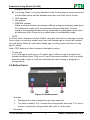
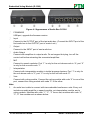
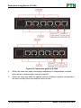
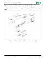
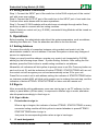
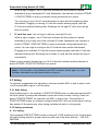
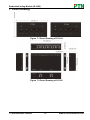
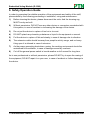
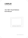
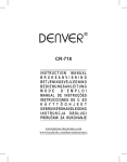
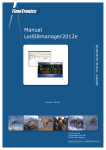
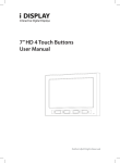
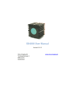
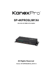
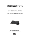
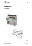
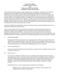
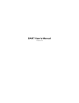
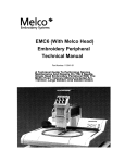
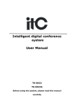
User Manual Embedded Voting Module D-3302C D-3302D D-3300 All Rights Reserved Version: D-3302_2014V1.0 Embedded Voting Module (D-3302) NOTICE: Please read this user manual carefully and take notice of Safety Operation Guide before using this product. Pictures shown in this manual are for reference only, different model and specifications are subject to real product. This manual is only for operation instruction, not for any maintenance usage. The functions described in this version are updated till March 2014. Any changes of functions and parameters since then will be informed separately. Please refer to the dealers for the latest details. This manual is copyright PTN Electronics Limited. All rights reserved. No part of this publication may be copied or reproduced without the prior written consent of PTN Electronics Limited. All product function is valid till 2014-03.10. Update History Version 1.0 Date 2014.03.10 PTN Electronics Limited Update Content First version. www.PTN-Electronics.com Embedded Voting Module (D-3302) Table of Contents 1. Introduction .................................................................................................................1 1.1 Introduction to D-3302 ....................................................................................... 1 1.2 Features ............................................................................................................ 1 1.3 Package Contents ............................................................................................. 1 1.3.1 Embedded Interpretation Module (D-3302) .............................................1 1.3.2 Audio Box (D-3300) .................................................................................1 2. Appearance of D-3302 ................................................................................................2 2.1 Top Panel........................................................................................................... 2 2.2 Bottom Panel ..................................................................................................... 3 3. Installation...................................................................................................................4 4. System Connection .....................................................................................................4 4.1 Connection between Embedded Voting Module (D-3302) and Audio Box (D-3300) .................................................................................................................. 4 4.2 Connection between Embedded Voting Module and control unit ....................... 7 4.3 Voting Module Connection ................................................................................. 8 5. Operations ..................................................................................................................8 5.1 Setting Address ................................................................................................. 8 5.2 Sign in................................................................................................................ 8 5.2.1 Sign in Mode:...........................................................................................8 5.3 Voting ................................................................................................................ 9 5.3.1 Start Voting ..............................................................................................9 5.3.2 Voting operations .....................................................................................9 5.3.3 Stop Voting ............................................................................................ 10 6. Specifications............................................................................................................ 11 7. Panel Drawing .......................................................................................................... 12 8. Troubleshooting & Maintenance ............................................................................... 13 9. Safety Operation Guide ............................................................................................ 14 10. After-sales Service ..................................................................................................15 PTN Electronics Limited www.PTN-Electronics.com Embedded Voting Module (D-3302) 1. Introduction 1.1 Introduction to D-3302 Embedded Voting Module (D-3302) is a voting module of Embedded Conference System, which includes chairman units (D-3302C) and delegate units (D-3302D). D-3302 supports 3 keys voting and IC-card & panel button sign-in function. Every button has one indicator to show real time working status for easy recognition. With a simple installation way, the voting unit is able to be applied in various conference occasions and provides a perfect efficient solution. 1.2 Features Special, simple and beautiful appearance design Simple operation with 1 key for sign in and 3 keys for voting Built-in IC card reader for IC-Card sign-in Every button is equipped with a LED indicator to show its real-time working status for easy recognition Chairman unit with ID A001 is able to start/ stop sign-in and voting in off-line state 1.3 Package Contents 1.3.1 Embedded Interpretation Module (D-3302) 1×Mounting bracket 2×Nuts 2×Set bolts 2×Butterfly screw 1×Shielded Twisted Pair 1.3.2 Audio Box (D-3300) 1×D-3300 2×Hangers 4×Screws (Black) 1×Shielded Twisted Pair Notes:Please confirm if the product and the accessories are all included, if not, please contact with the dealers. PTN Electronics Limited 1 www.PTN-Electronics.com Embedded Voting Module (D-3302) 2. Appearance of D-3302 2.1 Top Panel Figure 2-1 Top panels of D-3302C (Left) and D-3302D (Right) ① ATTEND / START/ATTEND Sign in For chairman unit (D-3302C) A001: 1. Start sign in (special owned by START/ATTEND button on chairman unit A001): In off-line mode (control unit is not connected with PC), when the indicator blink yellow, press this button to start a sign-in. 2. Sign in: When a sign-in has been started, the START/ATTEND indicator will blink yellow, press the button to sign in, it will turn yellow, thus the unit has successfully signed in. For delegate units (D-3302D) and other chairman units: When a sign-in has started, the ATTEND / START/ATTEND indicator will blink yellow, press the button to sign in, it will turn yellow, thus the unit has successfully signed in. Start voting (special owned by START/ATTEND button on chairman unit A001): In off-line mode (control unit is not connected with PC), when the indicator blink yellow, press this button to start a voting. ② 3 voting keys with LED indicator a) Not in a voting: When it begins setting address, the indicators will blink yellow until attendee press any button to set address. In normal working state, the PTN Electronics Limited 2 www.PTN-Electronics.com Embedded Voting Module (D-3302) indicators will be off. b) In a voting: When in a voting, indicators of the 3 voting keys on every connected unit will blink yellow until the attendee press any one of the 3 keys to vote. YES: approve NO: against ABSTAIN: abstain When a voting is finished, according to different voting result display mode (set in PC software for control unit), the indicators will show differently. Only the indicator of the pressed button will turn yellow when in transparent mode, while all indicators of the 3 keys will turn yellow when in confidentiality mode. ③ STOP In off-line mode, chairman unit with ID A001 can press this button to stop sign-in/voting. Once a sign in or voting is started, and if one unit finished sign in/ voting, the indicator will blink yellow. When all units have finished sign in/ voting, press this button to stop sign in/ voting. Note: STOP buttons on other chairman units take no action. ④ IC-card slot In IC-Card sign in mode, plug in IC card to sign in. When a sign in is started, the indicator will blink yellow. Plug in an IC card in the correct manner, it will turn yellow when the card is right, or it will blink red when the card is wrong or plugged in a wrong manner. 2.2 Bottom Panel Figure 2-2 Bottom panel ① ② Encoder Distinguish the units connected to the same audio box. The value is either 2 or 5. Connect the voting module with code “2” to one of the port, connect the voting module with code “5” to the other. Set screw PTN Electronics Limited 3 www.PTN-Electronics.com Embedded Voting Module (D-3302) Fix mounting bracket to unit. ③ RJ45 port Connect to an audio box with a straight-through cable. Note: Pictures shown in this manual are for reference only, different model and specifications are subject to real product. 3. Installation Firstly, dig a hole on the desk to the size marked on the aperture paper (shown in Figure 3-1). Then put the voting module into the hole and adjust it to flush with the table. Fix the mounting bracket to the module (shown in Figure 3-2). Plug a set screw into the fixing mounting and screw the nuts (with butterfly screw on the top) until the module arrives at the bottom. After that, the voting module is fixed on the table. Figure 3-1 Aperture paper Figure 3-2 Installation of D-3302 4. System Connection 4.1 Connection between Embedded Voting Module (D-3302) and Audio Box (D-3300) Connect Embedded Voting Module (D-3302) to control unit via Audio Boxes (D-3300) before starting a meeting. PTN Electronics Limited 4 www.PTN-Electronics.com Embedded Voting Module (D-3302) Figure 4-1 Appearance of Audio Box D-3300 ① FIRMWARE USB port, upgrade the firmware version ② Input Connect to the OUTPUT port of the last audio box. (Connect the INPUT port of the first audio box to the OUTPUT port of control unit.) ③ Output Connect to the INPUT port of next audio box. ④ Audio Output Connect with amplifiers to output audio. Do not support hot-plug, turn off the control unit before extracting the connected amplifiers. ⑤ MIC Connect to speech modules. Port “1” is only for the unit whose code is “4”; port “2” is only for the one with code “1”. ⑥ Interpretation Connect with interpretation module to tackle language barriers. Port “1” is only for the unit whose code is “3”; port “2” is only for the one with code “6”. ⑦ Vote Connect with voting module. Connect the voting module with code “2” to one of the port, connect the voting module with code “5” to the other. Note: 1. An audio box is able to connect with two embedded conference units. Every unit includes an audio amplifier, a speech module, an interpretation module, and a voting module. Modules with code “1”, “2”, “3” form a set, modules with code “4”, “5”, “6” form another set as shown below: PTN Electronics Limited 5 www.PTN-Electronics.com Embedded Voting Module (D-3302) Figure 4-2 Connection guide of D-3300 2. Within the same set, when connecting headphones to interpretation modules, there will be no sound output from the amplifier. 3. Within the same set, when the speech module is holding a speech, interpretation will work normally while the amplifier will be muted. PTN Electronics Limited 6 www.PTN-Electronics.com Embedded Voting Module (D-3302) 4.2 Connection between Embedded Voting Module and control unit Connect a voting module and an audio box with a straight-through cable; connect an audio box with another audio box or a control unit (exampled by D-3002) by cross-over cable. Figure 4-3 System Connection Diagram (Exampled by D-3002) PTN Electronics Limited 7 www.PTN-Electronics.com Embedded Voting Module (D-3302) 4.3 Voting Module Connection Step 1: Connect the INPUT port of the audio box to the RJ45 output port of the control unit with cross-over cables. Step 2: Connect the OUTPUT port of the audio box to the INPUT port of next audio box. Connect other audio boxes with the same operations. Step 3: Connect D-3302 modules with audio boxes via straight-through cable. Every audio box is able to connect with two voting modules. Step 4: Switch on control unit (e.g. D-3002), connected Voting Modules will be turned on synchronously. 5. Operations Before meeting, the administrator should set the system parameters, such as address, checking the status etc. Then the attendees are able to use the devices. 5.1 Setting Address To ensure the validity of connection between voting module and control unit, the administrator needs to set unit address if first use this system or have any changes of amount or replacement. When you need to set the address, operate your control unit (exampled by D-3002) abiding by the following steps: Menu - System Setting- Address. After setting the first address, press the Enter button to enable voting modules to set address. Meanwhile, all indicators will blink yellow to prompt users to set IDs. Press any button on each unit to set ID, and the indicators of button ATTEND / START/ATTEND will turn red, the control unit will recognize your unit and automatically set an ID for your unit. Press Exit on control unit to exit address setting, the indicator of START/ATTEND button on chairman module A001 will blink red to prompt you to undergo the next step, and the indicators of button ATTEND / START/ATTEND on other units will remain red. 5.2 Sign in After successfully setting addresses, users can start a sign in via PC software (on-line state) or panel button (off-line state). In response to different sign in mode, attendees should operate accordingly to finish sign in. 5.2.1 Sign in Mode: 1. Press button to sign in: When a sign in begins, the indicator of button ATTEND / START/ATTEND on every connected voting module will blink yellow to remind attendee to press ATTEND / START/ATTEND button to sign in. Just press the corresponding button when a sign in has begun. 2. IC card designated: PTN Electronics Limited 8 www.PTN-Electronics.com Embedded Voting Module (D-3302) When a sign in begins, the IC-Card slot indicator will blink yellow to remind attendee to plug in designated IC card. Meanwhile, the indicator of button ATTEND / START/ATTEND on every connected voting module will turn yellow. You can sign in only if the IC card information is same with the module’s preset information. Plugging in a wrong IC-Card will receive warning signal (with the IC-Card slot indicator blinking red). Exchange for the right IC card, and it will go back to normal. 3. IC card free seat: You can sign in with any recorded IC card. When a sign in begins, the IC-Card slot indicator will blink yellow to remind attendee to plug in any one of the recorded IC cards. Meanwhile, the indicator of button ATTEND / START/ATTEND on every connected voting module will turn yellow. You can sign in as long as the IC-Card has been written beforehand. Plugging in an unwritten IC-Card will receive warning signal (with the IC-Card slot indicator blinking red). Exchange for a written IC card, and the module will sign in successfully. When a voting module finished sign in, the IC-Card slot indicator and the indicator of button ATTEND / START/ATTEND will turn yellow. Note: In off-line state, only chairman unit A001 is able to start a sign in or vote. Besides, attendees can only press button to sign in. 5.3 Voting To calculate suggestions from attendees, chairman module A001 is able to start a vote in off-line state after sign-in in off-line state. 5.3.1 Start Voting After finishing sign in, the indicator of START/ATTEND button on chairman module A001 will blink yellow to prompt the attendee to press the button to start a voting. Press the button “START/ATTEND” on chairman unit A001 to start a vote. The indicator of START/ATTEND button on chairman voting module A001 will turn yellow when a voting has started. At the same time, other voting modules will work in voting mode. 5.3.2 Voting operations In a voting: Once pressed START/ATTEND to start a voting, all 3 LED indicators of the 3 voting keys will start blinking yellow to prompt users to press one of the three buttons – YES, NO, ABSTAIN. PTN Electronics Limited 9 www.PTN-Electronics.com Embedded Voting Module (D-3302) YES: press to support the present topic NO: veto the topic ABSTAIN: give up the voting right After a voting: According to different voting result display mode preset via PC software for control unit, voting modules will show differently. Confidential: Once you press down any one of the three voting keys, all voting key indicators will be on synchronously. Transparent: Once you press down any one of the three voting keys, the indicator of the key pressed will turn yellow, and other voting key indicators will turn off. Note: If there is problem running the device, the indicators will blink red. 5.3.3 Stop Voting In off-line state, when there are voting modules voted, the indicator of STOP button on the chairman voting module A001 will blink yellow to prompt the conference host to stop the voting. Press the button “Stop” on chairman unit A001 to stop the vote. Thus a voting is completed. Note: 1. In off-line state, when chairman voting module A001 stops a vote, the voting modules will return to the working status before sign in, i.e. users have to sign in again to undergo another voting. 2. A voting can be stopped at any time after there is at least 1 (included) voting module finished voting. PTN Electronics Limited 10 www.PTN-Electronics.com Embedded Voting Module (D-3302) 6. Specifications D-3302C&D Power Supply Connector Powered by control unit RJ45 Max Power Consumption (W) Weight (kg) Desk hole dimension (L*W) (mm) 0.2 0.32 Dimension (W*D*H)(mm) 100×52×75 D-3300 Power Consumption (W) 1.1W Color Black Weight(kg) 0.46 Dimension (W*D*H)(mm) 170×104×38 PTN Electronics Limited 11 102×43 www.PTN-Electronics.com Embedded Voting Module (D-3302) 7. Panel Drawing Figure 7-1 Panel Drawing of D-3304 Figure 7-2 Panel Drawing of D-3300 PTN Electronics Limited 12 www.PTN-Electronics.com Embedded Voting Module (D-3302) 8. Troubleshooting & Maintenance 1) Turning on control unit, voting module don’t turn on synchronously: Please check whether it is correctly connected without any loose Check if the control unit is energized normally 2) Users cannot operate the module normally: Check whether the module is connected in the correct manner without loose Make sure the connecting cables are good 3) In off-line state, IDA001 unit cannot start a sign in or vote, please check whether the unit A001 is a chairman unit. 4) Voting modules are connected successfully, but users cannot control the modules through front panel buttons or control software, the module may have already been broken. Please send it to the dealer for repairing. 5) If the static becomes stronger when connecting the modules, it probably due to bad grounding of the control unit, please check the grounding and make sure if the control unit is connected well, otherwise it would damage the control unit. PTN Electronics Limited 13 www.PTN-Electronics.com Embedded Voting Module (D-3302) 9. Safety Operation Guide In order to guarantee the reliable operation of the equipments and safety of the staff, please abide by the following proceeding in installation, using and maintenance: 1) Before cleaning the device, please disconnect the units. And the cleaning rag MUST be dry and soft. 2) Without permission, DO NOT use any other device or connectors unmatched with this system, in case of accident or increasing the damage of the device. 3) Do not put the device in a place of too hot or too wet. 4) DO NOT splash any chemistry substance or liquid in the equipment or around. 5) Put the device in a place of flat and steady, in case of damage due to vibration. 6) The extension cable should be away from people’s activity range, and no heavy thing upon it is allowed in case of extrusion. 7) As the power generating heat when running, the working environment should be maintained fine ventilation, in case of damage caused by overheat. 8) Cut off the general power switch in humid weather or left unused for long time. As to non-professional or without permission, please DO NOT try to open the casing of the equipment, DO NOT repair it on your own, in case of accident or further damage to the device. PTN Electronics Limited 14 www.PTN-Electronics.com Embedded Voting Module (D-3302) 10. After-sales Service 1) If there appear some problems when running the device, please check and deal with the problems reference to this user manual. Any transport costs are borne by the users during the warranty. 2) You can email to our after-sales department or make a call, please tell us the following information about your cases. Product version and name. Detailed failure situations. The formation of the cases. 3) We offer products for all six-month warranty, which starts from the first day you buy this product (calculated from the Invoice date). 4) Any problem is same with one of the following cases listed, we will not offer warranty service but offer for charge. Beyond the warranty. Damage due to incorrectly usage, keeping or repairing. Damage caused by the non-assigned maintenance company. No certificate or invoice as the proof of warranty. The product model showed on the warranty card does not match with the model of the product for repairing or had been altered. Damage caused by force majeure. Remarks: For any questions or problems, please try to get help from your local dealer, or to email PTN at: [email protected]. PTN Electronics Limited 15 www.PTN-Electronics.com www.PTN-Electronics.com PTN Electronics Limited Tel: +86-755-2846 1819 Fax: +86-755-8471 7796 Email: [email protected] Website: www.PTN-Electrionics.com