1
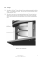
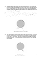
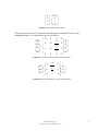
[ ] 8. Bring the Level #3 cable around ½ turn on its horizontal step, then wrap over onto the
vertical step of the same diameter and insert the free end into the termination on that
step.
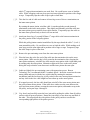
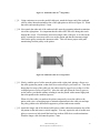
[ ] 9. Put one termination lug of the Level #4 cable into the termination in the final horizontal
step. Wrap the cable around ½ turn, then over to the largest vertical step.
[ ] 10. Rotate the Level #4 vertical step (the second termination worm is not yet installed) until
the free lug can be put into the last termination then rotate it back to take up any slack.
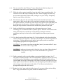
[ ] 11. Insert the second tensioner worm into the worm hole in the Level #4 vertical step and
tighten with the torque-driver to 0.23 N-m (32 oz-in). Remove any tape used as an aid
in the preceding steps.
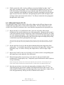
[ ] 12. Slowly move Joints 5 & 6 through their full motion ranges to confirm that the four
differential cables are properly installed and pre-tensioned. If new slack propagates
through the cables during this step, use the torque-driver to re-tighten the worms to 0.23
N-m (32 oz-in).
6.4 Differential Input (J5 & J6, M4 & M5)
Read Section 6.4.3 on pre-tensioning input circuits before continuing with these instructions.
6.4.1 Left Side
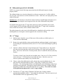
Before proceeding with the cabling steps below, orient the wrist so that the side labeled
"LEFT" is on your left, and the side labeled "RIGHT" is on your right. Rotate the wrist
completely counterclockwise and flip the wrist pitch to the right. This is the position the wrist
should remain in when cabling the left-side circuit.
6.4.1.1 3rd Stage
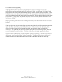
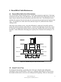
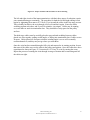
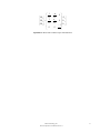
The cabling circuit for the left side 3rd-stage is represented in Figure 32.
Barrett Technology, Inc.
BA4-310 System User Manual Version 1.1
60