1
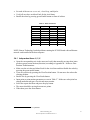
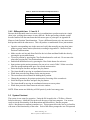
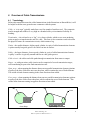
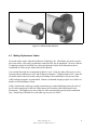
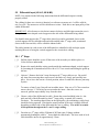
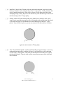
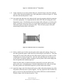
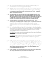
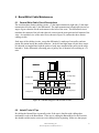
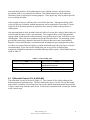
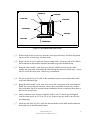
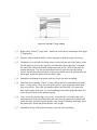
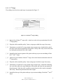
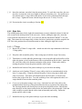
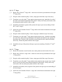
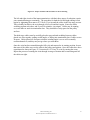
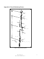
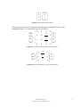
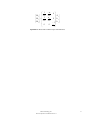
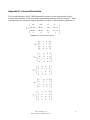
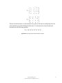
Appendix B - Motor-to-Joint Position Transformations The following transformations show the change in joint positions as a function of motor positions. The input transmission ratios and the differential transmission ratios are calculated from known pulley, pinion, and cable diameters. −1 0 N 1 Jθ 1 1 0 2N 2 Jθ 2 Jθ = − n3 3 0 Jθ 2N 2 4 0 0 0 Mθ 0 0 Mθ 1 0 Mθ 2 Mθ 3 1 N 4 0 −1 2N 2 − n3 2N 2 0 Equation 3: Arm Motor-to-Joint position transformations N 1 35.87 N 2 28.21 N = N 3 2 n3 1.68 N 17.77 4 Equation 4: Arm transmission ratios 1 Jθ 5 2 N 5 − n6 Jθ 6 = Jθ 2 N 5 7 0 1 2N 5 n6 2N 5 0 0 Mθ 4 0 Mθ 5 − 1 Mθ 6 N 7 Equation 5: Wrist Motor-to-Joint position transformations Barrett Technology, Inc. BA4-310 System User Manual Version 1.1 70