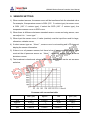
1
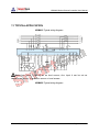
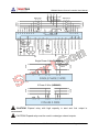
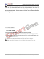
HGM400 Series Genset Controller (HGM410/HGM420) USER MANUAL ZHENGZHOU SMARTGEN TECHNOLOGY CO.,LTD Chinese trademark English trademark SmartGen — make your generator smart Smartgen Technology Co., Ltd. No. 28 Jinsuo Road Zhengzhou Henan Province P. R. China Tel: +86-371-67988888/67981888 +86-371-67991553/67992951 +86-371-67981000(overseas) Fax: 0086-371-67992952 Web: http://www.smartgen.com.cn http://www.smartgen.cn Email: [email protected] All rights reserved. No part of this publication may be reproduced in any material form (including photocopying or storing in any medium by electronic means or other) without the written permission of the copyright holder. Smartgen Technology reserves the right to change the contents of this document without prior notice. Version Date 2011-07-06 2012-03-15 2012-10-30 Version 1.0 1.1 1.2 2013-08-08 1.3 2013-08-28 1.4 2014-08-28 2015-05-27 1.5 1.6 Note Original release. Modify typical application. Modify some details. Change input port 3 and 4 to multiplex input port, that is to say, the input port 3 and input port 4 can be used as auxiliary input port or analog input port. Change “External Shutdown” input to “Emergency Shutdown” input. Some functions are added. Modify the description of output raise/drop speed. This manual is suitable for HGM400 series controller only. Clarification of notation used within this publication. SYMBOL INSTRUCTION Highlights an essential element of a procedure to ensure NOTE correctness. Indicates a procedure or practice, which, if not strictly observed, CAUTION! could result in damage or destruction of equipment. Indicates a procedure or practice, which could result in injury to WARNING! personnel or loss of life if not followed correctly. CONTENTS 1 2 3 4 OVERVIEW........................................................................................ 5 PERFORMANCE AND CHARACTERISTICS .................................... 6 SPECIFICATION ................................................................................ 8 OPERATION ...................................................................................... 9 4.1 PUSHBUTTONS ............................................................................................... 9 4.2 INDICATOR LIGHT ......................................................................................... 10 4.3 AUTOMATIC START/STOP OPERATION ...................................................... 11 4.4 MANUAL START/STOP OPERATION ............................................................ 12 5 PROTECTION ................................................................................. 13 5.1 WARNINGS .................................................................................................... 13 5.2 SHUTDOWN ALARM ..................................................................................... 16 6 7 CONNECTIONS .............................................................................. 19 DEFINITION AND RANGE OF PARAMETERS ................................ 22 7.1 PARAMETER CONTENTS AND RANGE (TABLE 1)...................................... 23 7.2 PROGRAMMABLE OUTPUT 1-5 (TABLE 2) .................................................. 31 7.3 PROGRAMMABLE INPUT 1-4 TABLE (ACTIVE WHEN CONNECT GND (B-) (TABLE 3)............................................................................................................... 32 7.4 SENSOR SELECT (TABLE 4) ........................................................................ 34 7.5 CONDITIONS OF CRANK DISCONNECT (TABLE 5) .................................... 35 8 9 10 11 12 PARAMETERS SETTING ................................................................ 36 SENSOR SETTING ......................................................................... 37 COMMISSIONING ........................................................................... 38 TYPICAL APPLICATION .................................................................. 39 INSTALLATION ................................................................................ 41 12.1 FIXING CLIPS ................................................................................................ 41 12.2 OVERALL DIMENSION AND PANEL CUTOUT.............................................. 42 13 FAULT FINDING .............................................................................. 44 HGM400 Series Genset Controller User Manual 1 OVERVIEW HGM400 series genset controllers integrate digitization, intelligentization and network technology which are used for genset automation and monitor control system of single unit to achieve automatic start/stop, data measurement, alarm protection and “three remote” (remote control, remote measuring and remote communication; SG485 module must be fitted). It fit with LCD display, optional languages interface (Chinese, English, Spanish, Turkish and Russian), and it is reliable and easy to use. HGM400 series genset controllers adopt micro-processor technology with precision parameters measuring, fixed value adjustment, time setting and set value adjusting and etc. All parameters can be configured from front panel or through programmable interface (USB to LINK, SG72 adaptor produced by Smartgen is recommended) via PC. It can be widely used in all types of automatic genset control system with compact structure, advanced circuits, simple connections and high reliability. HGM400 Series Genset Controller ISSUE 2015-05-27 Version 1.6 Page 5 of 44 HGM400 Series Genset Controller User Manual 2 PERFORMANCE AND CHARACTERISTICS HGM400 series controller has two types: HGM410: ASM (Automatic Start Module),it controls generator to start/stop by remote signal; HGM420: AMF (Auto Mains Failure), updates based on HGM410, moreover, has mains electric quantity monitoring and mains/generator automatic transfer control function, especially for automatic system composed by generator and mains. 132x64 LCD with backlight, selectable language interface (Chinese, English, Spanish, Turkish and Russian), push-button operation; Suitable for 3-phase 4-wire, 3-phase 3-wire, single phase 2-wire, and 2-phase 3-wire systems with voltage 120/240V and frequency 50/60Hz; Collects and shows 3-phase voltage, current, power parameter and frequency of generator or mains. Mains Generator Line Voltage (Uab, Ubc, Uca) Line Voltage (Uab, Ubc, Uca) Phase Voltage (Ua, Ub, Uc) Phase Voltage (Ua, Ub, Uc) Frequency (HZ) Frequency (HZ) Load Current (IA, IB, IC) Active Power (KW) Reactive Power (KVar) Apparent Power (KVA) Power Factor (PF) Accumulated Energy (kWh) For Mains, controller has over voltage, under voltage and loss of phase detection functions; For generator, controller has over voltage, under voltage, over frequency, under frequency and over current detection functions; Precision collect and display parameters about Engine, Temp. (WT) °C/°F both be displayed Oil pressure (OP) kPa/Psi/Bar all be displayed HGM400 Series Genset Controller ISSUE 2015-05-27 Version 1.6 Page 6 of 44 HGM400 Series Genset Controller User Manual Fuel Level (FL) % (Unit) Engine Speed (RP) RPM (Unit) Battery Voltage (VB) V (unit) Charger Voltage (VD) V (unit) Hours Counter (HC): Max. 999999 hours Start times: Max.999999 times Control & Protection: automatic start/stop of the genset, ATS(Auto Transfer Switch) control with perfect fault indication and protection function; With ETS(Energize To Stop), idle control, pre-heat control, speed raise control and speed drop control function, All output ports are relay-out; Parameter setting: parameters can be modified and cannot be lost even in case of power outage; all the controller parameters can be adjusted using front panel of the controller or via PC using an SG72 adaptor. Multiplex input port 3 and 4 can be used in various fields: input 3 can be used as auxiliary input port or fuel level sensor while input 4 can be used as auxiliary input port or configurable sensor. More kinds of curves of temperature, oil pressure, fuel level can be used directly and users can define the sensor curves by themselves; Configurable sensor: can be set as temperature sensor, oil pressure sensor or fuel level sensor, enable the detection of double temperature, double oil-pressure and double fuel level. Multiple crank disconnect conditions (magnetic pickup, oil pressure, generator frequency) are optional; Widely Power supply range: DC(8~35)V, suitable to different start battery voltage environment. All parameters used digital adjustment, instead of conventional analog modulation with normal potentiometer, more reliability and stability; Modular design, self-extinguished ABS plastic enclosure, pluggable connection terminals and embedded installation way; compact structure with easy mounting. HGM400 Series Genset Controller ISSUE 2015-05-27 Version 1.6 Page 7 of 44 HGM400 Series Genset Controller User Manual 3 SPECIFICATION Items Contents Working Voltage DC8. 0V to 35. 0V, Continuous Power Supply. Overall Consumption <3W(Standby mode: ≤2W) AC voltage Input: 3 Phase 4 Wire 2 Phase 3 Wire Single phase 2 Wire 3 Phase 3 Wire AC15V - AC360V (ph-N) AC15V - AC360V (ph-N) AC15V - AC360V (ph-N) AC30V - AC620V (ph-ph) Alternator Frequency 50Hz/60 Hz Speed Sensor Voltage 1.0V to 24V (RMS) Speed Sensor Frequency 10,000 Hz (max) Start Relay Output 5A DC28V power supply Auxiliary Relay Output 1 5A DC28V power supply Auxiliary Relay Output 2 5A DC28V power supply Auxiliary Relay Output 3 5A DC28V power supply Auxiliary Relay Output 4 5A AC250V voltage-free output Auxiliary Relay Output 5 5A AC250V voltage-free output Overall Dimensions 130mm x 112mm x 39mm Panel Cutout 110mm x 90mm CT Secondary Current 5A (rated) Working Condition Temperature: (-25~70)ºC; Humidity: (20~93)%RH Storage Condition Temperature: (-25~70)ºC Protection Level IP55 Gasket Insulation Intensity Apply AC2.2kV voltage between high voltage terminal and low voltage terminal; The leakage current is not more than 3mA within 1min. Weight 0.26kg HGM400 Series Genset Controller ISSUE 2015-05-27 Version 1.6 Page 8 of 44 HGM400 Series Genset Controller User Manual 4 OPERATION 4.1 PUSHBUTTONS Stop/ Reset Stop running generator in Auto/Manual mode; In case of alarm condition, pressing the button will reset alarm; In stop mode, pressing and holding the button for 3 seconds will test indicator lights (lamp test); During stopping process, press this button again to stop generator immediately. Start Start genset in Manual/Test mode. Pressing this key will set the module into manual mode. Manual Pressing and adjust LCD contrast. Auto Pressing this key will set the module into auto mode. Set/Confirm Up/Increase Down/Decrease (or ) simultaneously can Pressing this key will enter into Main Menu; In setting parameter status, press this key will shift cursor or confirm setting value. Scrolls the screen up; Shift the cursor up or increase the set value in parameter setting menu. Scrolls the screen down; Shift the cursor down or decrease the set value in parameter setting menu. HGM400 Series Genset Controller ISSUE 2015-05-27 Version 1.6 Page 9 of 44 HGM400 Series Genset Controller User Manual 4.2 INDICATOR LIGHT HGM410 Panel Indicators HGM420 Panel Indicators HGM400 Series Genset Controller ISSUE 2015-05-27 Version 1.6 Page 10 of 44 HGM400 Series Genset Controller User Manual 4.3 AUTOMATIC START/STOP OPERATION Auto mode is selected by pressing the button; a LED besides the button will illuminate to confirm the operation. Auto Start Sequence, 1) HGM420: when mains is abnormal (over/under voltage, loss of phase), enter into “Mains Abnormal Delay” and LCD displays count down time. “Start Delay” timer is initiated after the delay has expired. 2) HGM410: When “Remote Start” is active, “Start Delay” timer is initiated; 3) “Start Delay” countdown will be displayed on LCD; 4) When start delay is over, preheat relay energizes (if configured), “preheat delay XXs” information will be displayed on LCD; 5) After the above delay, the Fuel Relay is energized, and then one second later, the Start Relay is engaged. The engine is cranked for a pre-set time. If the engine fails to fire during this cranking attempt then the fuel relay and start relay are disengaged for the pre-set rest period; “crank rest time” begins and wait for the next crank attempt. 6) Should this start sequence continue beyond the set number of attempts, the start sequence will be terminated, the fourth line of LCD display will be highlighted with HGM400 Series Genset Controller ISSUE 2015-05-27 Version 1.6 Page 11 of 44 HGM400 Series Genset Controller User Manual black and Fail to Start fault will be displayed. 7) In case of successful crank attempt, the “Safety On” timer is activated, allowing Low Oil Pressure, High Temperature, Under speed, Charge Alternator Failure and Auxiliary inputs (configured) to stabilise without triggering the fault. As soon as this delay is over, “start idle” delay is initiated (if configured). 8) During “start idle” delay, under speed, under frequency, under voltage alarms are inhibited. When this delay is over, “warming up” delay is initiated (if configured). 9) After the “warming up” delay, if generator status is normal, its indicator will be illuminated. If generator voltage and frequency have reached on-load requirements, then the generator close relay will be energized; genset will take load; generator power indicator will illuminate and generator will enter into Normal Running status. If voltage or frequency is abnormal, the controller will initiate shutdown alarm (alarm information will be displayed on LCD). Auto Stop Sequence, 1) HGM420: During normal running process, if mains normal, enters into “Mains Normal Delay”. When mains indicator illuminates, “Stop Delay” is initiated. 2) HGM410: When the “Remote Start” signal is removed, the Stop Delay is initiated. 3) Once this “stop delay” has expired, the Generator Breaker will open and the “Cooling Delay” is then initiated. After “Transfer Delay”, the mains close relay will be energized; mains will take load; generator power indicator will extinguish while mains power indicator will illuminate. 4) During “Stop Idle” Delay (if configured), idle relay is energized. 5) “ETS Solenoid Hold” begins, ETS relay is energized while fuel relay is de-energized. 6) "Fail to Stop Delay" begins, complete stop is detected automatically. 7) Generator is placed into its standby mode after its complete stop. Otherwise, fail to stop alarm is initiated and the corresponding alarm information is displayed on LCD. 4.4 MANUAL START/STOP OPERATION 1) HGM420: Manual mode is selected by pressing the button; a LED besides the button will illuminate to confirm the operation; Press then choose “Test Mode”. Under the two modes, press key, select “Mode Select”, button to start the genset, it can automatically judge crank success and accelerate to high speed running. If high temperature, low oil pressure, over speed and abnormal voltage occur during genset HGM400 Series Genset Controller ISSUE 2015-05-27 Version 1.6 Page 12 of 44 HGM400 Series Genset Controller User Manual running, controller can effectively protect genset to stop (detail procedures please refer to No.4~9 of Auto start sequence). Under Manual Mode , if mains normal, load breaker won’t transfer; if mains abnormal, load breaker will transfer to generator. Under Test Mode, after genset high speed normal running, no matter mains normal or not, load will be transferred to generator. 2) HGM410: Manual mode is selected by pressing the button; a LED besides the button will illuminate to confirm the operation; Then press button to start the generator, it can automatically judge crank success and accelerate to high speed running. If high temperature, low oil pressure, over speed and abnormal voltage occur during genset running, controller can effectively protect genset to stop (detail procedures please refer to No.4~9 of Auto start sequence). After genset high speed normal running, controller will send Gen Closed signal. 3) Manual stop: pressing key can stop the running genset. (detail procedures please refer to No.3~7 of Auto stop sequence) 5 PROTECTION 5.1 WARNINGS Warnings are not shutdown alarms and do not affect the operation of the gen-set. Warning alarms does not lead to shutdown. The alarm information will be displayed on LCD. Warning alarms types are as follows: No. 1 2 Items Description When the controller detects that engine temperature has exceeded the pre-set value while shutdown is prohibited, or High detects that the Aux. input high temperature while shutdown Temperature is prohibited, it will initiate a warning alarm and the corresponding alarm information will be displayed on LCD. When the controller detects that the oil pressure has fallen below the pre-set value while shutdown is prohibited, or Low Oil detects that the Aux. input low oil pressure while shutdown is Pressure prohibited, it will initiate a warning alarm and the corresponding alarm information will be displayed on LCD. HGM400 Series Genset Controller ISSUE 2015-05-27 Version 1.6 Page 13 of 44 HGM400 Series Genset Controller User Manual 3 Gen Current Over 4 Fail To Stop 5 Low Fuel Level 6 Charge Failure 7 Battery Under Volt 8 Battery Over Volt 9 Auxiliary Input 10 Loss Of Speed Signal 11 Low Coolant Level 12 Temp. Sensor Open 13 Oil Pressure Sensor Open Alt When the controller detects that the genset current has exceeded the pre-set value and the over current delay has expired, it will initiate a warning alarm and the corresponding alarm information will be displayed on LCD. After “fail to stop” delay/ ETS delay has expired, if gen-set does not stop completely, it will initiate a warning alarm and the corresponding alarm information will be displayed on LCD. When the controller detects that the fuel level has fallen below the pre-set value while shutdown is prohibited, or detects that the Aux. input low fuel level while shutdown is prohibited, it will initiate a warning alarm and the corresponding alarm information will be displayed on LCD. When the controller detects that charger voltage has fallen below the pre-set value, it will initiate a warning alarm and the corresponding alarm information will be displayed on LCD. When the controller detects that battery voltage has fallen below the pre-set value, it will initiate a warning alarm and the corresponding alarm information will be displayed on LCD. When the controller detects that battery voltage has exceeded the pre-set value, it will initiate a warning alarm and the corresponding alarm information will be displayed on LCD. When the controller detects that the auxiliary input warning signals, it will initiate a warning alarm and the corresponding alarm information will be displayed on LCD. When the controller detects that the engine speed is 0 and the delay is 0, it will initiate a warning alarm and the corresponding alarm information will be displayed on LCD. When the controller detects the low coolant level input is active, it will initiate a warning alarm and the corresponding alarm information will be displayed on LCD. When the controller detects that the temperature sensor is open circuit and the action select “Warn”, it will initiate a warning alarm and the corresponding alarm information will be displayed on LCD. When the controller detects that the oil pressure sensor is open circuit and the action select “Warn”, it will initiate a warning alarm and the corresponding alarm information will be displayed on LCD. HGM400 Series Genset Controller ISSUE 2015-05-27 Version 1.6 Page 14 of 44 HGM400 Series Genset Controller User Manual 14 Level Open 15 Temp. Sensor 2 Open 16 Oil Pressure Sensor 2 Open 17 Level Sensor 2 Open 18 High Temperature 2 19 Low Oil Pressure 2 20 Low Fuel Level 2 21 Sensor Maintenance Due When the controller detects that the level sensor is open circuit and the action select “Warn”, it will initiate a warning alarm and the corresponding alarm information will be displayed on LCD. If the config. sensor set as temperature sensor, When the controller detects that the temperature sensor is open circuit and the action select “Warn”, it will initiate a warning alarm and the corresponding alarm information will be displayed on LCD. If the config. sensor set as oil pressure sensor, When the controller detects that the oil pressure sensor is open circuit and the action select “Warn”, it will initiate a warning alarm and the corresponding alarm information will be displayed on LCD. If the config. sensor set as level sensor, When the controller detects that the level sensor is open circuit and the action select “Warn”, it will initiate a warning alarm and the corresponding alarm information will be displayed on LCD. When the controller detects that config. sensor temperature (sensor type: temperature sensor) has exceeded the pre-set value while shutdown is prohibited, it will initiate a warning alarm and the corresponding alarm information will be displayed on LCD. When the controller detects that config. sensor oil pressure (sensor type: oil pressure sensor) has fallen below the pre-set value while shutdown is prohibited, it will initiate a warning alarm and the corresponding alarm information will be displayed on LCD. When the controller detects that config. sensor fuel level (sensor type: level sensor) has fallen below the pre-set value while shutdown is prohibited, it will initiate a warning alarm and the corresponding alarm information will be displayed on LCD. When genset running time has exceeded the user setting maintenance time and the action select “Warn”, it will initiate a warning alarm and the corresponding alarm information will be displayed on LCD. The maintenance alarm will reset if the action select “Inactive”. HGM400 Series Genset Controller ISSUE 2015-05-27 Version 1.6 Page 15 of 44 HGM400 Series Genset Controller User Manual 5.2 SHUTDOWN ALARM When controller detects shutdown alarm, it will send signal to open breaker and shuts down generator. The alarm information will be displayed on LCD. Shutdown alarms as following: No Items Description When the controller detects that the emergency shutdown Emergency 1 signal, it will initiate a shutdown alarm and the corresponding Shutdown alarm information will be displayed on LCD. When controller detects that the water/cylinder temperature High has exceeded the pre-set value, it will initiate a shutdown 2 Temperature alarm and the corresponding alarm information will be displayed on LCD. When the controller detects that the oil pressure has fallen Low Oil below the pre-set value, it will initiate a shutdown alarm and 3 Pressure the corresponding alarm information will be displayed on LCD. When the controller detects that the generator speed has 4 Over Speed exceeded the pre-set value, it will initiate a shutdown alarm and the corresponding alarm information will be displayed on HGM400 Series Genset Controller ISSUE 2015-05-27 Version 1.6 Page 16 of 44 HGM400 Series Genset Controller User Manual No Items 5 Under Speed 6 Loss Of Speed Signal 7 Gen Voltage 8 Gen Under Voltage 9 Gen Current 10 Fail To Start 11 Gen Over Frequency 12 Gen Under Frequency 13 No Gens Frequency 14 Low Fuel Level 15 Low Coolant Level 16 Temp. Sensor Over Over Description LCD. When the controller detects that the generator speed has fallen below the pre-set value, it will initiate a shutdown alarm and the corresponding alarm information will be displayed on LCD. When the controller detects that the engine speed is 0 and the delay is NOT 0, it will initiate a shutdown alarm and the corresponding alarm information will be displayed on LCD. When the controller detects that the genset voltage has exceeded the pre-set value, it will initiate a shutdown alarm and the corresponding alarm information will be displayed on LCD. When the controller detects that the genset voltage has fallen below the pre-set value, it will initiate a shutdown alarm and the corresponding alarm information will be displayed on LCD. When the controller detects that the genset current has exceeded the pre-set value and delay is not 0, it will initiate a shutdown alarm and the corresponding alarm information will be displayed on LCD. If the engine does not fire after the pre-set number of attempts, it will initiate a shutdown alarm and the corresponding alarm information will be displayed on LCD. When the controller detects that the genset frequency has exceeded the pre-set value, it will initiate a shutdown alarm and the corresponding alarm information will be displayed on LCD. When the controller detects that the genset frequency has fallen below the pre-set value, it will initiate a shutdown alarm and the corresponding alarm information will be displayed on LCD. When the controller detects that the genset frequency is 0, it will initiate a shutdown alarm and the corresponding alarm information will be displayed on LCD. When the controller detects that the fuel level has fallen below the pre-set value or detects that the low fuel level input is active, it will initiate a shutdown alarm and the corresponding alarm information will be displayed on LCD. When the controller detects the low coolant level input is active, it will initiate a shutdown alarm and the corresponding alarm information will be displayed on LCD. When the controller detects that the temperature sensor is HGM400 Series Genset Controller ISSUE 2015-05-27 Version 1.6 Page 17 of 44 HGM400 Series Genset Controller User Manual No Items Open 17 Oil Pressure Sensor Open 18 Level Open 19 Temp. Sensor 2 Open 20 Oil Pressure Sensor 2 Open 21 Level Sensor 2 Open 22 High Temperature 2 23 Low Oil Pressure 2 24 Low Fuel Level 2 25 Maintenance Due Sensor Description open circuit and the action select “Shutdown”, it will initiate a shutdown alarm and the corresponding alarm information will be displayed on LCD. When the controller detects that the oil pressure sensor is open circuit and the action select “Shutdown”, it will initiate a shutdown alarm and the corresponding alarm information will be displayed on LCD. When the controller detects that the level sensor is open circuit and the action select “Shutdown”, it will initiate a shutdown alarm and the corresponding alarm information will be displayed on LCD. If the config. sensor set as temperature sensor, When the controller detects that the temperature sensor is open circuit and the action select “Shutdown”, it will initiate a shutdown alarm and the corresponding alarm information will be displayed on LCD. If the config. sensor set as oil pressure sensor, When the controller detects that the oil pressure sensor is open circuit and the action select “Shutdown”, it will initiate a shutdown alarm and the corresponding alarm information will be displayed on LCD. If the config. sensor set as level sensor, When the controller detects that the level sensor is open circuit and the action select “Shutdown”, it will initiate a shutdown alarm and the corresponding alarm information will be displayed on LCD. When the controller detects that config. sensor temperature (sensor type: temperature sensor) has exceeded the pre-set value, it will initiate a shutdown alarm and the corresponding alarm information will be displayed on LCD. When the controller detects that config. sensor oil pressure (sensor type: oil pressure sensor) has fallen below the pre-set value, it will initiate a shutdown alarm and the corresponding alarm information will be displayed on LCD. When the controller detects that config. sensor fuel level (sensor type: level sensor) has fallen below the pre-set value, it will initiate a shutdown alarm and the corresponding alarm information will be displayed on LCD. When genset running time has exceeded the user setting maintenance time and the action select “Shutdown”, it will initiate a shutdown alarm and the corresponding alarm information will be displayed on LCD. The maintenance alarm will reset if the action select “Inactive”. HGM400 Series Genset Controller ISSUE 2015-05-27 Version 1.6 Page 18 of 44 HGM400 Series Genset Controller User Manual 6 CONNECTIONS Compared with HGM420, HGM410 has no Mains AC Voltage input terminals. The rear panel of HGM410 and HGM420 is as below. HGM400 Series Genset Controller ISSUE 2015-05-27 Version 1.6 Page 19 of 44 HGM400 Series Genset Controller User Manual Description of terminal connections: Cable Pin Function Size 1 B- 1.5mm2 2 B+ 1.5mm2 3 Aux. Output 1 1.0mm2 4 Crank 1.0mm2 5 6 Aux. Output 2 Aux. Output 3 1.0mm2 1.0mm2 7 Aux. Input 1 1.0mm2 8 Aux. Input 2 1.0mm2 9 Aux. Input 3 1.0mm2 10 Aux. Input 4 1.0mm2 HGM400 Series Genset Controller Description Connected with negative of starter battery. DC power supply. Connected with positive of starter battery. If wire length is over 30m, better to double wires in parallel. Max. 20A fuse is recommended. B+ is supplied by 2 point, rated 5A. Crank Relay Output; B+ is supplied by 2 point, rated 5A. Connect to starter coil. B+ is supplied by 2 point, rated 5A. B+ is supplied by 2 point, rated 5A. Ground connected is active (B-) Ground connected is active (B-) See Table 3 Ground connected is active (B-); Can be used as Level Sensor. Ground connected is ISSUE 2015-05-27 Version 1.6 Page 20 of 44 HGM400 Series Genset Controller User Manual Pin Function Temperature Cable Size 11 Engine Sensor 12 Oil Press Sensor 1.0mm2 13 Current IA 1.5mm2 14 Current IB 1.5mm2 15 Current IC 1.5mm2 16 Current COM 1.5mm2 1.0mm2 17 Magnetic Pickup 0.5mm2 18 Charger D+ 1.0mm2 19 Aux. Output 4 1.0mm2 20 Aux. Output 5 1.0mm2 21 Aux. Output COM 1.5mm2 22 Gen AC Voltage U 1.0mm2 23 Gen AC Voltage V 1.0mm2 24 Gen AC Voltage W 1.0mm2 25 Gen AC Voltage N2 1.0mm2 26 Mains AC Voltage R 1.0mm2 27 Mains AC Voltage S 1.0mm2 28 Mains AC Voltage T 1.0mm2 HGM400 Series Genset Controller Description active (B-); Can be used as Config. Sensor. Connect to temperature/cylinder resistance sensor. See Table 4 Connect to oil pressure resistance sensor. Outside connected to secondary coil of current transformer(rated 5A) Outside connected to secondary coil of current transformer(rated 5A) Outside connected to secondary coil of current transformer(rated 5A) See INSTALLATION in this manual. Connect to speed sensor; Shielded wire is recommended. The other end of speed sensor connects to B-. Connect to charging starter’s D+ terminal. If there is no this terminal, then be hang up. The combination of terminal 19 and 21 is relay normally open contact; rated 5A; Voltage free. The combination of terminal 20 and 21 is relay normally open contact; rated 5A; Voltage free. Common terminal of auxiliary output 4 and 5. Connected to U-phase of generator (2A fuse is recommended) Connected to V-phase of generator (2A fuse is recommended) Connected to W-phase of generator (2A fuse is recommended) Connected to N-wire of generator. Connected to R-phase of mains (2A fuse is recommended) (HGM410 without) Connected to S-phase of mains (2A fuse is recommended) (HGM410 without) Connected to T-phase of mains (2A fuse ISSUE 2015-05-27 Version 1.6 Page 21 of 44 HGM400 Series Genset Controller User Manual Pin 29 Function Mains AC Voltage N1 Cable Size 1.0mm2 Description is recommended) (HGM410 without) Connected to N-wire of mains (HGM410 without) NOTE: LINK interface is parameters programmable interface that can be programmed by PC using an SG72 adapter. If there is need to remote control the genset, please use the SG485 module produced by our company. 7 DEFINITION AND RANGE OF PARAMETERS HGM400 Series Genset Controller ISSUE 2015-05-27 Version 1.6 Page 22 of 44 HGM400 Series Genset Controller User Manual 7.1 PARAMETER CONTENTS AND RANGE (TABLE 1) No Items Range 1 Mains Delay Normal 2 Mains Delay Abnormal 3 Mains Voltage Under 4 Mains Voltage Over 5 Transfer Delay Rest 6 Default (0-3600)s 10 (0-3600)s 5 (30-620)V 184 (30-620)V 276 (0-99.9)s 1.0 Start Delay (0-3600)s 1 7 Stop Delay (0-3600)s 1 8 Start Attempts (1-10)times 3 9 Preheat Time (0-300)s 0 10 Cranking Time (3-60)s 8 11 Crank Rest Time (3-60)s 10 HGM400 Series Genset Controller ISSUE 2015-05-27 Description The time from mains abnormal to normal or from normal to abnormal; suitable for ATS (automatic transfer switch). When mains voltage has fallen below the set value, Mains Under Voltage is active. When set the value as 30V, the controller does not detect under voltage signal. Back lash: 10V When mains voltage has exceeded the set value, Mains Over Voltage is active. When set the value as 620V, the controller does not detect over voltage signal. Back lash: 10V Interval time from mains switch off to generator switch on; or from generator switch off to mains switch on. Time from mains abnormal or remote start signal is active to start genset. Time from mains normal or remote start signal is deactivated to genset stop. Maximum crank times of crank attempts. When reach this number, controller will send start failure signal. Power-on time of heater plug before starter is powered up. Power-on time of starter The waiting time before second power up when engine start fail. Version 1.6 Page 23 of 44 HGM400 Series Genset Controller User Manual No Items Range Default 12 Safety On Delay (1-60)s 10 13 Start Idle Time (0-3600)s 0 14 Warming Up Time (0-3600)s 10 15 Cooling Time (3-3600)s 10 16 Stop Idle (0-3600)s 0 17 ETS Hold (0-120)s 20 18 Fail to Stop Delay (0-120)s 0 19 Breaker Time (0-10)s 5.0 20 Flywheel Teeth (10-300) 118 21 Gen Delay (0-20.0)s 10.0 22 Gen Over Voltage (30-620)V 264 Solenoid Close Abnormal HGM400 Series Genset Controller ISSUE 2015-05-27 Description Alarms for low oil pressure, high temperature, under speed, under frequency/voltage, charge alt failure are inactive. Idle running time of genset when starting. Warming time between genset switch on and high speed running. Radiating time before genset stop, after it unloads. Idle running time when genset stop. Stop electromagnet’s power on time when genset is stopping. Time between ending of genset idle delay and stopped when “ETS time” is set as 0; Time between ending of ETS hold delay and stopped when “ETS time” is not 0. Pulse width of mains/generator switch on. When it is 0, means output constantly. Tooth number of the engine, for judging of starter crank disconnect conditions and inspecting of engine speed. See the installation instructions. The alarm delay of generator over voltage and under voltage. When generator voltage has exceeded the set value and the “Gen abnormal delay” has expired, Gen Over Voltage is active. When set the value as 620V, the controller does not detect over voltage signal. Version 1.6 Page 24 of 44 HGM400 Series Genset Controller User Manual No Items Range Default 23 Generator Under Voltage (30-620)V 196 24 Under Speed (0-6000)RPM 1200 25 Over Speed (0-6000)RPM 1710 26 Under Frequency (0-75.0)Hz 45.0 27 Over Frequency (0-75.0)Hz 57.0 28 High Temperature (80-140)ºC 98 HGM400 Series Genset Controller ISSUE 2015-05-27 Description When generator voltage has fallen below the set value and the “Gen abnormal delay” has expired, Gen Under Voltage is active. When set the value as 30V, the controller does not detect under voltage signal. When engine speed has fallen below the set value for 10s, Under Speed is active. It will initiate a shutdown alarm signal. When engine speed has exceeded the set value for 2s, Over Speed is active. It will initiate a shutdown alarm signal. When generator frequency has fallen below the set value but Not equal to 0 for 10s, Under Frequency is active. It will initiate a shutdown alarm signal. When generator frequency has exceeded the set value for 2s, Over Frequency is active. It will initiate a shutdown alarm signal. When the temperature value of the external temperature sensor exceeds the set value, “High Temperature” timer is initiated. Detecting only after safety on delay has expired. If the set value is 140, high temperature signal will not be sent (this only concerns external temperature sensor, not high temperature signal via config. input port). Version 1.6 Page 25 of 44 HGM400 Series Genset Controller User Manual No Items Range Default 29 Low Oil Pressure (0-400)kPa 103 30 Low Fuel Level (0-100)% 10 31 Config. Sensor (80-140)ºC (0-400)kPa (0-100)% 98 103 10 32 Loss of Signal (0-20.0)s 5.0 33 Charge Alt Failure (0-30)V 6.0 34 Battery Voltage Over (12-40)V 33.0 35 Battery Voltage Under (4-30)V 8.0 Speed HGM400 Series Genset Controller ISSUE 2015-05-27 Description When the external pressure sensor value falls below this set value, “Low Oil Pressure” timer is initiated. Detecting only after safety on delay has expired. If the set value is 0, low oil pressure signal will not be sent (this only concerns pressure sensor and does not concern low oil pressure warning signal via configurable input port) When the liquid level of the external sensor falls below the set value, “Low Fuel Level” timer is initiated. (this only concerns fuel level sensor and does not concern low fuel level warning signal via configurable input port) Each value correspond to above 28 (Temperature sensor), 29 (Oil pressure sensor) and 30 (Level sensor), respectively. If the set value is 0, only warning and not to shutdown the generator. During generator is normal running, when alternator D+(WL) voltage has fallen below the set value and remains for 5s, It will initiate a shutdown alarm signal. When battery voltage has exceeds the set value and remains for 20s, It will initiate a warning alarm signal. Only warning and not to shutdown the generator. When battery voltage has fallen below the set value and remains for 20s, It will initiate a warning alarm signal. Only warning and not to shutdown the generator. Version 1.6 Page 26 of 44 HGM400 Series Genset Controller User Manual No Items 36 Current Trans. Full Load Current Rating 37 Range Default (5-6000)/5 500 (5-6000)A 500 Description The ratio of external CT Generator’s rated current, used for load over current calculating. When the load current has exceeded the set value, “over current” delay is initiated. When load current has exceeded the set value and the “over current” delay has expired, over current alarm is initiated. When the set value is 0, only warning and not to shutdown the generator. When fuel level has fallen below the set value for 10s, “Fuel Pump On” alarm is initiated. When fuel level has exceeded the set value for 10s, “Fuel Pump Off” alarm is initiated. Factory default: Fuel Relay Output Factory default: Energized To Stop Factory default: Idle Control Factory default: Close Generator Factory default: Mains Closed Factory default: High Temperature Input 38 Over Current Percentage (50-130)% 120 39 Over Delay (0-3600)s 1296 40 Fuel Pump On (0-100)% 25 41 Fuel Pump Off (0-100)% 80 42 Aux. Output 1 (0-17) 14 43 Aux. Output 2 (0-17) 2 44 45 46 Aux. Output 3 Aux. Output 4 Aux. Output 5 (0-17) (0-17) (0-17) 3 5 6 47 Aux. Input 1 (0-15) 1 (0-1) 0 (0-20.0)s 2.0 (0-15) 2 Factory default: Low Oil Pressure Warning Input (0-1) 0 Factory default: Close to active (0-20.0)s 2.0 (0-15) 10 Factory default: Remote Start (0-1) 0 Factory default: Close to active 48 49 50 51 52 53 54 Current Aux. Input Active Aux. Input Delay Aux. 1 1 Input 2 Aux. Input Active Aux. Input Delay Aux. Input 3 Aux. Input Active 2 2 3 HGM400 Series Genset Controller ISSUE 2015-05-27 Factory default: Close to active Version 1.6 Page 27 of 44 HGM400 Series Genset Controller User Manual No 55 56 57 58 Items Range Aux. Input Delay Aux. Input 4 Aux. Input Active Aux. Input Delay 3 4 4 Default (0-20.0)s 2.0 (0-15) 11 Factory default: Fuel Level Warn (0-1) 0 Factory default: Close to active (0-20.0)s 2.0 59 Power On Mode (0-2) 0 60 Module Address (1-254) 1 61 Passwords (0-9999) 1234 62 Crank Disconnect (0-5) 2 63 Disconnect Magnetic Pickup (0-3000)RPM 360 64 Disconnect Generator Freq (10.0-30.0)Hz 14.0 65 Disconnect Pressure 66 Oil Description (0-400)kPa 200 High Temperature Inhibit (0-1) 0 67 Low Oil Pressure Inhibit (0-1) 0 68 Low Fuel Level Inhibit (0-1) 1 HGM400 Series Genset Controller ISSUE 2015-05-27 0: Stop Mode 1: Manual Mode 2: Auto Mode Communication controller. address of There are 3 conditions of disconnecting starter with engine: Generator Frequency, Magnetic Pickup, Oil Pressure. Each condition can be used alone and simultaneously to separating the start motor and genset as soon as possible. See Table 5 When engine speed higher than the set value, starter will be disconnected. When generator frequency higher than the set value, starter will be disconnected. When generator oil pressure higher than the set value, starter will be disconnected. Factory default: when high temperature occurs, shutdown alarm is initiated. Note 1 Factory default: when low oil pressure occurs, shutdown alarm is initiated. Note 2 Factory default: when low fuel level occurs, shutdown alarm is initiated. Note 2 Version 1.6 Page 28 of 44 HGM400 Series Genset Controller User Manual No Items 69 Config. Inhibit 70 AC System 71 72 Sensor Temp. Sensor Curve Pressure Sensor Curve Range Default Description Factory default: when config. sensor value higher/lower than the set value (particular case depends on the sensor type), shutdown alarm is initiated. Note 2 0: 3P4W; 1: 2P3W 2: 1P2W; 3: 3P3W Note 3 (0-1) 1 (0-3) 0 (0-9) 08 SGX (0-9) 08 SGX 73 Multiplex Input 1 (0-1) 0 0: Aux. Input 3 1: Level Sensor Note 4 74 Level Curve (0-5) 3 SGD Sensor 75 Multiplex Input 2 76 Config. Curve 77 Poles 78 Temperature Sensor Open (0-2) 1 79 Oil Pressure Sensor Open (0-2) 1 80 Fuel Level Sensor Open (0-2) 1 81 Config. Open Sensor (0-2) 1 Cooling On Cooling Off Blower (0-140)℃ 60 (0-140)℃ 40 82 83 Sensor Blower (0-3) 0 (0-9) (0-9) (0-5) (2-32) 8 8 3 4 HGM400 Series Genset Controller ISSUE 2015-05-27 0: Aux. Input 4 1: Temperature Sensor 2: Oil Pressure Sensor 3: Level Sensor Note 4 SGX SGX SGD 0: Indication (temperature sensor will show “+++”); 1:Warn; 2:Shutdown 0: Indication (oil pressure sensor will show “+++”); 1:Warn; 2:Shutdown 0: Indication (fuel level sensor will show “+++”); 1:Warn; 2:Shutdown 0: Indication (LCD display will show “+++”); 1:Warn; 2:Shutdown It controls the cooling blower to open or close if the output port is configured as Cooling Blower. Version 1.6 Page 29 of 44 HGM400 Series Genset Controller User Manual No Items Range Default Description When the liquid level of the external sensor falls below the set value, “Low Fuel Level” timer is initiated. (this only concerns fuel level sensor and does not concern low fuel level warning signal via configurable input port) 0: Disable 1: Enable Use for setting the maintenance interval. 84 Low Fuel Level Warn (0-100)% 20 85 Maintenance Enable (0-1) 0 86 Maintenance Due (0-5000)h 30 87 Maintenance Due Action (0-1) 0 0: Warn 88 Custom Curve 0 It can be customized as Temp. sensor, OP sensor, Fuel level sensor and Config. sensor curve. Sensor (0-3) 1: Shutdown Note 1, if “high temperature inhibit” is configured, or set auxiliary input as “inhibit high temperature stop” and this input is active, when temperature is higher than the preset value, or high temperature alarm input is active, controller will send warning signal only and not stop the unit. Note 2, if “low oil pressure inhibit” is configured, or set auxiliary input as “inhibit low oil pressure stop” and this input is active, when oil pressure is lower than the preset value, or low oil pressure alarm input is active, controller will send warning signal only and not stop the unit. Note 3, if “3P3W” is selected, maximum shutdown threshold of “Mains Over Voltage” and “Gens Over Voltage” can be set as 620V; when select others, maximum shutdown threshold can be set as 360V. Note 4, Multiplex Input can be set as “auxiliary input” or “level sensor”; if one of them is set successfully, then the corresponding items are active. For instance, if set “Multiplex Input 3” as “Auxiliary Input”, the related configuration items of auxiliary input 3 are active; if set “Multiplex Input 3” as “Level Sensor”, the related configuration items of level sensor are active; HGM400 Series Genset Controller ISSUE 2015-05-27 Version 1.6 Page 30 of 44 HGM400 Series Genset Controller User Manual 7.2 PROGRAMMABLE OUTPUT 1-5 (TABLE 2) No Items 0 Not Used 1 Common Alarm 2 Energized to Stop 3 Idle Control 4 5 Preheat Control Close Generator 6 Mains Closed 7 Open ATS 8 Raise Speed 9 Drop Speed 10 Generator Run 11 Fuel Pump Control 12 High Speed Control 13 14 In Auto Mode Fuel Relay Output 15 Generator Excite 16 17 Air Cooler Output Description Output port is deactivated when “Not Used” is selected. Include all shutdown alarms and warning alarms. When there is warning alarm only, it is not self-lock; when a shutdown alarm occurs, it is self-lock until the alarm is reset. Suitable for genset with electromagnet and will active after “stop idle delay”. It is deactivated when the “ETS Solenoid delay” expires. Used for engine which has idles. Close before starting and open in warming up delay; Close during stop idle delay and open when stop is completed. Close before starting and open before power up; When close time is 0, it’s continuous output. When close time is 0, it’s continuous output. (HGM410 without) When close time is 0, it’s disabled. Close when the generator enters into Warming Up delay (close time: warming up delay) while open when Aux. Close when the generator enters into Stop Idle delay/ Energized to Stop delay (close time: Stop Idle delay) while open when Aux. Action when genset is normal running while deactivated when engine speed is lower than the “crank disconnect speed”. Close when fuel level is lower than the “Fuel Pump On” value or when low fuel level warning input is active; Open when fuel level is higher than the “Fuel Pump Off” and low fuel level warning input is deactivated; Close when the generator enters into Warming Up delay while open after cooling delay. The controller is in automatic mode. To control fuel relay output. Output in start period. If there is no generator frequency during safety running, output for 2 seconds. Control air cooler to start\stop according to cooler temperature. Reserved HGM400 Series Genset Controller ISSUE 2015-05-27 Version 1.6 Page 31 of 44 HGM400 Series Genset Controller User Manual 7.3 PROGRAMMABLE INPUT 1-4 CONNECT GND (B-) (TABLE 3) No 0 1 2 3 4 5 6 7 8 9 WHEN Emergency Input Stop Shutdown alarm will be immediately initiated if this input is active. When the gen-set is running normally and this signal is activated, if there is a high temperature situation, the High Temperature controller will first cool down the generator and then Stop Input stop it; if the signal is deactivated and a high temperature situation occurs, the controller will shut down the gen-set without cooling down. Generator Closed Input Mains Closed Input HGM410 without Inhibit High When it is active, prohibit stopping when high Temperature Stop temperature occurs. Note 1 Inhibit Low Oil When it is active, prohibit stopping when low oil Pressure Stop pressure occurs. Note 2 Remote Start 11 Fuel Level Warn 12 Coolant Level Warn 14 (ACTIVE Items Description Not Used High Temperature If these signals are active after safety on delay, Input shutdown alarm will be immediately initiated. Low Oil Pressure Warning Input Only warning and not stops if this input is active. Auxiliary Warning 10 13 TABLE Fuel Shutdown Coolant Shutdown HGM420 without Level Level 15 Auto Start Inhibit 16 17 18 Reversed Reversed Panel Lock HGM400 Series Genset Controller In Auto mode, if this input is active, whether mains is normal or not (HGM420) or a remote start signal occurs (HGM410), the controller will not give a start command to the generator. If generator is normal running, stop command won’t be executed. When this input is deactivated, genset will automatically start or stop according to the mains status (normal or abnormal). When input is active, all keys expect the “Up\Down” ISSUE 2015-05-27 Version 1.6 Page 32 of 44 HGM400 Series Genset Controller User Manual No Items 19 Manual/Auto Switch 20 21 22 23 24 25 26 27 28 29 30 31 Reversed Reversed Reversed Reversed Reversed Reversed Reversed Reversed Reversed Reversed Reversed Reversed HGM400 Series Genset Controller Description buttons are inactive. When input is active, enter into auto mode automatically, panel buttons and local operation are inactive; When input is inactive, enter into manual mode automatically, remote operation is inhibited. ISSUE 2015-05-27 Version 1.6 Page 33 of 44 HGM400 Series Genset Controller User Manual 7.4 SENSOR SELECT (TABLE 4) No 1 Temperature Sensor 2 Pressure Sensor 3 Fuel Level Sensor Content 0 Not used 1 User Defined Resistive Type 2 VDO 3 SGH(Huanghe sensor) 4 SGD(Dongkang sensor) 5 CURTIS 6 DATCON 7 VOLVO-EC 8 SGX 9 Reserved 0 Not used 1 User Defined Resistive Type 2 VDO 10Bar 3 SGH(Huanghe sensor) 4 SGD(Dongkang sensor) 5 CURTIS 6 DATCON 7 VOLVO-EC 8 SGX 9 Reserved 0 Not used 1 User Defined Resistive Type 2 SGH 3 SGD 4 Reserved 1 5 Reserved 2 HGM400 Series Genset Controller ISSUE 2015-05-27 Description Defined resistive range is (0~6000)Ω, default is SGX sensor. Defined resistive range is (0~6000)Ω, default is SGX sensor. Defined resistive range is (0~6000)Ω, default is SGD sensor. Version 1.6 Page 34 of 44 HGM400 Series Genset Controller User Manual 7.5 CONDITIONS OF CRANK DISCONNECT (TABLE 5) No Content 0 Magnetic pickup 1 Generator Frequency 2 Magnetic pickup + Generator Frequency 3 Magnetic pickup + Oil pressure 4 Generator Frequency + Oil pressure 5 Generator Frequency + Magnetic pickup + Oil pressure 1. There are 3 conditions to make starter separate with engine; magnetic pickup, generator frequency can be used separately while oil pressure must be used together with magnetic pickup and generator frequency. The aim is to disconnect the starter motor as soon as possible. 2. Magnetic pickup is the magnetic equipment which be installed in starter for detecting flywheel teeth. 3. When set as magnetic pickup, must ensure that the number of flywheel teeth is as same as setting, otherwise, “over speed shutdown” or “under speed shutdown” may be caused. 4. If genset without magnetic pickup, please don’t select corresponding items, otherwise, “start fail” or “loss speed signal” maybe caused. 5. If genset without oil pressure sensor, please don’t select corresponding items. 6. If not select generator frequency in crank disconnect setting, controller will not collect and display the relative power quantity (can be used in water pump set); if not select magnetic pickup in crank disconnect setting, the engine speed displayed in controller is calculated by generator signal. HGM400 Series Genset Controller ISSUE 2015-05-27 Version 1.6 Page 35 of 44 HGM400 Series Genset Controller User Manual 8 PARAMETERS SETTING Start the controller, then press to enter into the parameters setting menu, see fig 1 below: Fig1 1 2 3 4 Set Parameters Information Language Mode Select Parameters Setting When entering password interface, inputting “1234” can set part of the parameter items in Table 1 while “0318” can set all the items. If there is need to set more parameters (e.g. voltage calibration; current calibration), please contact the factory. NOTES: 1. For HGM410, there are no items from 1 to 5 in Table 1; there are no mains items in auxiliary output 1-5. 2. Please change the controller parameters when generator is in standby mode only (e. g. Crank disconnect conditions selection, auxiliary input, auxiliary output, various delay), otherwise, shutdown and other abnormal conditions may occurs. 3. Over voltage set value must be higher than under voltage set value, otherwise over voltage and under voltage condition may occur simultaneously. 4. Over speed set value must be higher than under speed set value, otherwise over speed and under speed condition may occur simultaneously. 5. Please set the generator frequency value as low as possible when cranking, in order to make the starter be separated quickly as soon as possible. 6. Auxiliary input 1~4 could not be set as same items; otherwise, there are abnormal functions. However, the auxiliary output 1~5 can be set as same items. 7. If need to shut down after cooling, please set any auxiliary input as “High Temperature Stop Input”, then connect this input port to GND. Information LCD will display software version, issue date of the controller. Note: In this interface, press will display the auxiliary inputs and outputs status. Language Chinese, English, Spanish, Turkish and Russian interface can be selected. Mode Select The controller can be set as Test Mode, Manual Mode, Auto Mode or Stop Mode. Note: Pressing key at any time will quit the setting and return to the HGM400 Series Genset Controller ISSUE 2015-05-27 Version 1.6 Page 36 of 44 HGM400 Series Genset Controller User Manual previous setting menu. 9 SENSOR SETTING 1) When reselect sensors, the sensor curve will be transferred into the standard value. For example, if temperature sensor is SGH (120°C resistor type), its sensor curve is SGH (120°C resistor type); if select the SGD (120°C resistor type), the temperature sensor curve is SGD curve. 2) When there is difference between standard sensor curves and using sensor, user can adjust it in “curve type”. 3) When input the sensor curve, X value (resistor) must be input from small to large, otherwise, mistake occurs. 4) If select sensor type as “None”, sensor curve is not working and LCD does not display the sensor information. 5) If there is no oil pressure sensor, but there is low oil pressure alarm switch, user must set the oil pressure sensor as “None”, otherwise, maybe low oil pressure shutdown occurs. 6) The headmost or backmost values in the vertical coordinates can be set as same as below, Common unit conversion table 1Pa 1kgf/cm2 1bar 1psi N/m2 (pa) kgf/cm2 bar (p/in2.psi) 1 9.8x10⁴ 1x10⁵ 6.89x10³ 1.02x10⁻⁵ 1 1.02 7.03x10⁻² 1x10⁻⁵ 0.98 1 6.89x10⁻² 1.45x10⁻⁴ 14.2 14.5 1 ISSUE 2015-05-27 Version 1.6 Page 37 of 44 HGM400 Series Genset Controller HGM400 Series Genset Controller User Manual 10 COMMISSIONING Please make sure the following checks are made before commissioning, 1. Ensure all the connections are correct and wires diameter is suitable. 2. Ensure that the controller DC power has fuse, controller’s positive and negative connected to start battery are correct. 3. Take proper action to prevent engine to crank success (e. g. Remove the connection wire of fuel valve). If checking is OK, make the start battery power on; choose manual mode and controller will executive routine. 4. Set controller under manual mode, press “start” button, genset will start. After the cranking times as setting, controller will send signal of Start Failure; then press “stop” to reset controller. 5. Recover the action to prevent engine to crank success (e. g. Connect wire of fuel valve), press start button again, genset will start. If everything goes well, genset will normal running after idle running (if idle run be set). During this time, please watch for engine’s running situations and AC generator’s voltage and frequency. If abnormal, stop genset and check all wires connection according to this manual. 6. Select the AUTO mode from controller’s panel, connect mains signal. After the mains normal delay, controller will transfer ATS (if fitted) into mains load. After cooling time, controller will stop genset and make it into “at rest” mode until there is mains abnormal situation. 7. When mains is abnormal again, genset will be started automatically and enter into normal running, then controller send signal to making generator switch on, and control the ATS transfer into generator load. If not like this, please check ATS’ wires connection according to this manual. 8. If there is any other question, please contact Smartgen’s service. HGM400 Series Genset Controller ISSUE 2015-05-27 Version 1.6 Page 38 of 44 HGM400 Series Genset Controller User Manual 11 TYPICAL APPLICATION HGM410 Typical wiring diagram Note: Aux. Input 3 can be set as level sensor; Aux. Input 4 can be set as temperature sensor, oil pressure sensor or level sensor. HGM420 Typical wiring diagram HGM400 Series Genset Controller ISSUE 2015-05-27 Version 1.6 Page 39 of 44 HGM400 Series Genset Controller User Manual Single Phase 2 Wire (HGM420) 2 Phase 3 Wire (HGM420) CAUTION! Expand relay with high capacity in start and fuel output is recommend. CAUTION! Expand relay must be used in mains/gen closed outputs. HGM400 Series Genset Controller ISSUE 2015-05-27 Version 1.6 Page 40 of 44 HGM400 Series Genset Controller User Manual CAUTION! Let its normally closed contact series connect between fuel relay output port and electromagnetic valve when you connect emergency stop button on the controller. Emergency stop alarm can be displayed if you configure one input port as “Emergency Shutdown” (one end connect to normally open contact, the other end connect to ground). 12 INSTALLATION 12.1 FIXING CLIPS Controller is panel built-in design; it is fixed by clips when installed. 1) Withdraw the fixing clip screw (turn anticlockwise) until it reaches proper position. 2) Pull the fixing clip backwards (towards the back of the module) ensuring two clips are inside their allotted slots. 3) Turn the fixing clip screws clockwise until they are fixed on the panel. Note: Care should be taken not to over tighten the screws of fixing clips. HGM400 Series Genset Controller ISSUE 2015-05-27 Version 1.6 Page 41 of 44 HGM400 Series Genset Controller User Manual 12.2 OVERALL DIMENSION AND PANEL CUTOUT 1) Battery Voltage Input HGM400 Series Genset Controller ISSUE 2015-05-27 Version 1.6 Page 42 of 44 HGM400 Series Genset Controller User Manual HGM400 series controller can suit for widely range of battery voltage DC(8~35)V. Negative of battery must be connected with the engine shell. The diameter of wire which from power supply to battery must be over 1.5mm2. If floating charge configured, please firstly connect output wires of charger to battery’s positive and negative directly, then, connect wires from battery’s positive and negative to controller’s positive and negative input ports in order to prevent charge disturbing the controller’s normal working. 2) Speed Sensor Input Speed sensor is the magnetic equipment which be installed in starter and for detecting flywheel teeth. Its connection wires to controller should apply for 2 cores shielding line. The shielding layer should connect to No. 1 terminal in controller while another side is hanging in air. The else two signal wires are connected to No.1 and No.17 terminals in controller. The output voltage of speed sensor should be within AC(1~24)V (effective value) during the full speed. AC12V is recommended (in rated speed). When install the speed sensor, let the sensor is spun to contacting flywheel first, then, port out 1/3 lap, and lock the nuts of sensor at last. 3) Output And Expansion Relay All outputs of controller are relay contact output type. If need to expand the relays, please add freewheel diode to both ends of expand relay’s coils (when coils of relay has DC current) or, add resistance-capacitance return circuit (when coils of relay has AC current), in order to prevent disturbance to controller or others equipment. 4) AC Input HGM400 series controller must be connected to outside current transformer. And the current transformer’s secondary side current must be 5A. At the same time, the phases of current transformer and input voltage must correct. Otherwise, the collected current and active power maybe not correct. CAUTION!ICOM port must be connected to negative pole of battery. WARNING! When there is load current, transformer’s secondary side prohibit open circuit. 5) Withdraw Voltage Test When controller had been installed in control panel, if need the high voltage test, HGM400 Series Genset Controller ISSUE 2015-05-27 Version 1.6 Page 43 of 44 HGM400 Series Genset Controller User Manual please disconnect controller’s all terminal connections, in order to prevent high voltage into controller and damage it. 13 FAULT FINDING Symptom Possible Remedy Check starting batteries; Controller no response Check controller connection wirings; with power. Check DC fuse. Check the water/cylinder temperature is too high or not; Genset shutdown Check the genset AC voltage; Check DC fuse. Low oil pressure alarm Check the oil pressure sensor and its connections. after crank disconnect High water temp. alarm Check the temperature sensor and its connections. after crank disconnect Check related switch and its connections according to Shutdown Alarm During the information on LCD; Running Check auxiliary inputs. Check fuel circuit and its connections; Check starting batteries; Fail to Start Check speed sensor and its connections; Refer to engine manual. Check starter connections; Starter no response Check starting batteries. Genset running while ATS Check ATS; not transfer Check the connections between ATS and controllers. HGM400 Series Genset Controller ISSUE 2015-05-27 Version 1.6 Page 44 of 44