1
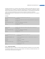
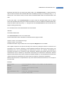
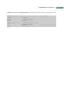
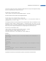
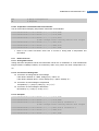
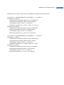
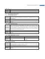
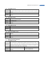
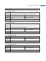
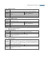
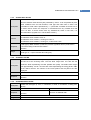
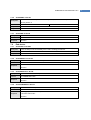
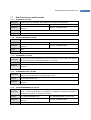
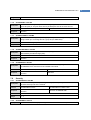
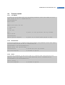
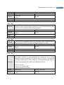
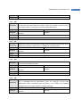
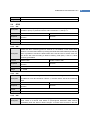
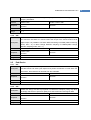
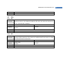
ProBee-ZE10 User Guide Rev.1.6.2 0 (Low) and 1 (High) if the pins are configured as digital I/O lines. If the pins are configured as analog inputs, the corresponding return values are shown as *. AT+DIO?<CR> or AT+DIO<number>?<CR> , where <number> is the specific IO number between ranges 0 ~ 12 to read AT+DIO command can also be used to set the digital output lines. AT+DIO=<value><CR> or AT+DIO<number>=<value><CR> , where <number> is the specific IO number between ranges 0 ~ 12 to read, and the <values> is a combination of 0 or 1, 0 = Low, 1 = High The analog input values can be read using the AT+AI command. Return value is a combination of 16-bit hexadecimal integer between 0~2EE0(0~1200mV) or D120-FFFF(-1200~-1mV) which unit value corresponds to 0.1mv. To convert the hexadecimal value to the actual voltage, please use the formula below. If the pins are configured as digital I/Os, the corresponding return values are shown as *. AT+AI?<CR> or AT+AI<number>?<CR> , where <number> is the specific IO number between ranges 0 ~ 3 to read If the Value is between 0 ~ 2EE0, Voltage (mV) = Value * 0.1 If the Value is between D120 ~ FFFF, Voltage (mV) = (Value – 65536) * 0.1 Example) AT+DIO?<CR> 10001**011100 analog inputs DIO 0, 4, 8, 9, 10 are ON. GPIO5, 6 are configured as OK AT+DIO0=0<CR> OK AT+DIO?<CR> 00001**011100 inputs DIO 4, 8, 9, 10 are ON. GPIO5, 6 are configured as analog OK AT+AIO?<CR> ****,****,192A,13E8 configured as DIO. AI 2, 3(GPIO5, 6) are used. The others are OK To get/set the I/O values of the remote devices, remote AT commands can be used as below. 45