1
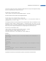
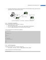
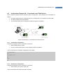
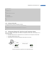
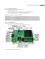
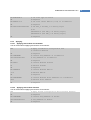
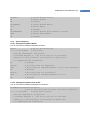
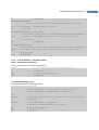
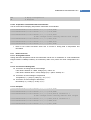
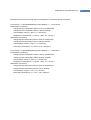
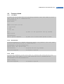
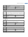
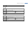
ProBee-ZE10 User Guide Rev.1.6.2 6.5 Configuration Example #2: 1 Coordinator and 2 End-Devices Here is another example assuming different system configurations. This example can be described as follows: One ZE10 module acts as a coordinator and it is connected to a host computer via serial cable. Two ZE10 modules act as end-devices. Turn on/off the LEDs of the end-devices remotely through the coordinator Figure 6-4 Example #2: 1 Coordinator and 2 End-Devices 6.5.1 Coordinator Configuration Hardware configuration for the coordinator is as follows: Set the HOST switch to UART Connect a serial cable between a host computer and the coordinator The AT commands for coordinator configuration is as follows: AT+NODETYPE=1 OK AT+PANID=7772 OK ATZ OK 6.5.2 End-devices Configuration Hardware configuration for the coordinator is as follows: Set the GPIO_OUT switch to LED_ON The AT commands for the end-devices are as follows: 55